DM860A - Multimeter GREENLEE - Free user manual and instructions
Find the device manual for free DM860A GREENLEE in PDF.
| Product Type | Professional Digital Multimeter |
| Brand and Model | Greenlee DM860A |
| Display | LCD 50,000 counts (high resolution 500,000 counts), 41-segment bargraph, dual display |
| Main Measurements | AC/DC voltage (1000 V max), AC/DC current (10 A max), resistance, capacitance, frequency, temperature (type K, dual channel), conductance, diode, continuity, duty cycle, dBm, 4-20 mA loop current |
| DC Voltage Accuracy | ±(0.02% + 0.02 mV) on 500 mV; ±(0.02% + 0.0002 V) on 5 V; ±(0.03% + 0.002 V) on 50 V; etc. |
| True RMS | True RMS AC, AC+DC, 100 kHz bandwidth on voltage, 20 kHz on current |
| Special Functions | MAX/MIN/AVG, peak capture (CREST), relative zero, hold (HOLD), VFD mode, Beep‑Jack™ detection, auto power-off (APO), backlight |
| PC Interface | USB optical port compatible with DMSC‑9U (optional), Windows software |
| Power Supply | 1 x 9 V battery (NEDA 1604, JIS 006P, IEC 6F22) |
| Typical Battery Life | Approximately 17 minutes of inactivity before auto-power-off (APO) |
| Dimensions (estimated) | 200 × 100 × 50 mm |
| Weight (estimated) | Approximately 600 g with battery |
| Safety | Double insulation, CAT IV 1000 V, complies with IEC/UL/EN61010‑1, protection fuses (11 A/1000 V and 0.44 A/1000 V) |
| Operating Temperature | 0 °C to 45 °C (32 °F to 113 °F), relative humidity 0% to 80% (non-condensing) |
| Maintenance | Clean with damp cloth and mild detergent; remove battery if unused for more than 60 days |
| Warranty | Limited lifetime warranty for original purchaser |
| Included Accessories | Set of test leads, type K thermocouple (2 channels), user manual |
| Options | USB optical interface with software (ref. DMSC‑9U) |
Frequently Asked Questions - DM860A GREENLEE
User questions about DM860A GREENLEE
0 question about this device. Answer the ones you know or ask your own.
Ask a new question about this device
Download the instructions for your Multimeter in PDF format for free! Find your manual DM860A - GREENLEE and take your electronic device back in hand. On this page are published all the documents necessary for the use of your device. DM860A by GREENLEE.
USER MANUAL DM860A GREENLEE
INSTRUCTION MANUAL MANUAL DE INSTRUCCIONES MANUEL D'INSTRUCTIONS

natural_image
Black diamond-shaped logo with a white letter 'G' in the center, no additional text or symbols.GREENLEE®
text_image
0.00000 SELECT RANGE HOLDING CREST REC0 D1% mV Ti + nS A 164.3mA mA μA H2V OFF A mA μA COM DV-+ L-T2+ MAX 16A MAX 16A HBO PUSED HBO PUSED T1+ MAX 16A MAX 16A HBO PUSED 16A HV-DM-860A
Digital Multimeter
Multímetro digital
Read and understand all of the instructions and safety information in this manual before operating or servicing this tool.
The Greenlee DM-860A Digital Multimeter is a hand-held testing device with the following measurement capabilities: AC and DC voltage, AC and DC current, percent of loop current, two channels of temperature (K-type thermocouples), frequency, duty cycle, resistance, conductance, and capacitance. It also checks diodes and verifies continuity.
The DM-860A features a bar graph display that responds more quickly than the numeric display—useful for detecting faulty contacts, potentiometer clicks, and signal spikes. An optional optically isolated computer interface with software facilitates the recording of readings from the meter to a computer.
Other specialized functions and capabilities include:
- Dual display shows two measurements, such as AC voltage and frequency, at the same time.
- Beep-Jack™ audible warning alerts the user with a beep and an error message on the LCD if the test lead is plugged into the mA μA or A input terminal while the selector switch is not in the mA μA or A position.
- AC bandwidth to 100 kHz for voltage or 20 kHz for current.
- MAX/MIN function which stores the maximum, minimum, and average.
- Crest capture mode to capture voltage or current signal peaks.
- Selectable between 50,000 or 500,000 counts resolution when measuring DC voltage.
- Relative zero mode.
• Automatic or manual ranging.
• Intelligent automatic power off. - Backlighted LCD for reading in dim conditions.
Safety
Safety is essential in the use and maintenance of Greenlee tools and equipment. This instruction manual and any markings on the tool provide information for avoiding hazards and unsafe practices related to the use of this tool. Observe all of the safety information provided.
Purpose of This Manual
This instruction manual is intended to familiarize all personnel with the safe operation and maintenance procedures for the Greenlee DM-860A Digital Multimeter.
Keep this manual available to all personnel. Replacement manuals are available upon request at no charge at www.greenlee.com.

Do not discard this product or throw away!
For recycling information, go to www.greenlee.com.
Important Safety Information

SAFETY ALERT SYMBOL
This symbol is used to call your attention to hazards or unsafe practices which could result in an injury or property damage. The signal word, defined below, indicates the severity of the hazard. The message after the signal word provides information for preventing or avoiding the hazard.
DANGER
Immediate hazards which, if not avoided, WILL result in severe injury or death.
WARNING
Hazards which, if not avoided, COULD result in severe injury or death.
CAUTION
Hazards or unsafe practices which, if not avoided, MAY result in injury or property damage.
natural_image
Illustration of a hand interacting with an open book (no text or symbols visible)WARNING
Read and understand this material before operating or servicing this equipment. Failure to understand how to safely operate this tool could result in an accident causing serious injury or death.

WARNING
Electric shock hazard: Contact with live circuits could result in severe injury or death.
All specifications are nominal and may change as design improvements occur. Greenlee Tools, Inc. shall not be liable for damages resulting from misapplication or misuse of its products.
® Registered: The color green for electrical test instruments is a registered trademark of Greenlee Tools, Inc.
Beep-Jack is a trademark of BTC.
Microsoft and Windows are registered trademarks of Microsoft Corporation.
Important Safety Information
WARNING
Electric shock and fire hazard:
- Do not expose this unit to rain or moisture.
- Do not use the unit if it is wet or damaged.
- Only use the test leads provided with the equipment or UL Listed Probe Assembly with same rating or better.
- Inspect the test leads or accessory before use. They must be clean and dry, and the insulation must be in good condition. Do not use the test lead if the contrasting inner layer of insulation is visible.
- Use this unit for the manufacturer's intended purpose only, as described in this manual. Any other use can impair the protection provided by the unit.
Failure to observe these warnings could result in severe injury or death.
WARNING
Electric shock hazard:
- Do not apply more than the rated voltage between any two input terminals, or between any input terminal and earth ground.
- Do not contact the test lead tips or any uninsulated portion of the accessory.
Failure to observe these warnings could result in severe injury or death.
WARNING
Electric shock hazard:
- Do not operate with the case open.
- Before opening the case, remove the test leads from the circuit and shut off the unit.
Failure to observe these warnings could result in severe injury or death.
WARNING
Electric shock hazard:
The fuses are an integral part of the overvoltage protection. When fuse replacement is necessary, refer to “Specifications” for the correct type, size, and capacity. Using any other type of fuse will void the overvoltage protection rating of the unit.
Failure to observe this warning could result in severe injury or death.
Important Safety Information
WARNING
Electric shock hazard:
- Unless measuring voltage, current, or frequency, shut off and lock out power. Make sure that all capacitors are discharged. Voltage must not be present.
- Set the selector and connect the test leads so that they correspond to the intended measurement. Incorrect settings or connections can result in a blown fuse.
- Using this unit near equipment that generates electromagnetic interference can result in unstable or inaccurate readings.
Failure to observe these warnings could result in severe injury or death.
CAUTION
Electric shock hazard:
Do not change the measurement function while the test leads are connected to a component or circuit.
Failure to observe this precaution may result in injury and can damage the unit.
CAUTION
Electric shock hazard:
- Do not attempt to repair this unit. It contains no user-serviceable parts.
- Do not expose the unit to extremes in temperature or high humidity. Refer to “Specifications.”
Failure to observe these precautions may result in injury and can damage the unit.
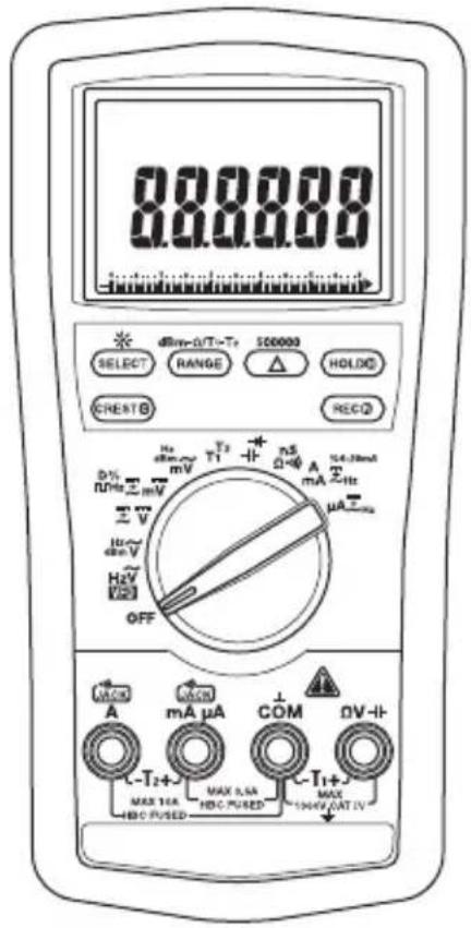
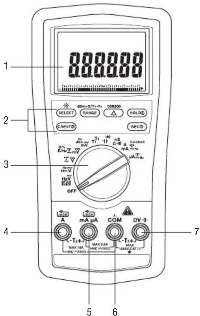
Identification
- Display LCD and bar graph
- Feature Buttons Refer to explanations under "Using the Features"
- Selector Selects a function or turns power OFF
- A Positive input terminal for high current measurements; negative input terminal for T2
- mA A Positive input terminal for low current measurements; positive input terminal for T2
- COM Negative, common, or ground input terminal for all measurements
- V -11- Positive input terminal for all measurements except current
text_image
1 8.8.8.8.8 SELECT 4BmΩ/T1-T2 520300 HOLD CREST REC D% mV T2 Π nS A N-2mA ΩHz mV Ω+Φ mA μA μA Hz V OFF JACK A mA μA COM ΩV C-T2+ MAX 10A HRC PUSED MAX 2.6A HRC PUSED C-T1+ MAX 1000V.CAT IV 7 5 6Symbols on the Unit


Warning—Read the instruction manual
Double insulation
Display Icons
Primary Display
-
Bar graph element
-
- Polarity indicator for bar graph
-
Bar graph scale
-
Relative zero function is enabled.
-
VFD VFD function is enabled.
-
- Polarity indicator
-
8.8.8.8.88 Numeric display
-
T1-T2 T1, T2, or T1-T2 function is enabled.
-
AC measurement is selected.
-
=DC measurement is selected.
-
MAX Maximum value being recorded or displayed.
-
MIN Minimum value being recorded or displayed.
-
AVG Average value being recorded or displayed.
-
R Record function is enabled.
-
Crest capture function is enabled.
-
Hold function is selected.
-
Automatic ranging is enabled.
-
Continuity
-
-
- Low battery
-
-
▶ Overload symbol (bar graph display)
-
5 Bar graph maximum range indicator
-
D% Duty cycle function is enabled.
-
k Kilo (10 3)
-
M Mega (106)
-
Ω Ohm
-
Hz Hertz (frequency in cycles per second)
-
dBm Decibel
-
m Milli (10 ^-3 )
-
μ Micro (10 -6)
-
V Volt
-
A Ampere
-
n Nano (10 -9)
-
F Farad
-
S Siemen
Secondary Display
-
%4-20mA Industrial process control loop current function is enabled.
-
μ Micro (10 -6)
-
m Milli (10 ^-3 )
-
A Ampere
-
V Volt
-
M Mega (106)
-
k Kilo (10 3)
-
Hz Hertz (frequency in cycles per second)
-
8.8.8.8 Numeric display
-
T2 T2 function is enabled.
-
AC measurement is selected.
-
- Polarity indicator

text_image
24 AUTO R C H MAX MIN AVG 25 26 51-53 50 MkHz μmAV %4-20mA 47-49 43-46 42 16-17 T1-T2 VFD 8.8.8.8.8.8 0.0.0.0.0.0 13-14 12 11 10 8-9 D%kMΩHzdBmpVAnFS 29-41 28 27Using the Features
- Dual Digital Display: This meter can display two measurements, such as AC voltage and frequency, at the same time. Display combinations are shown using large symbols to indicate the measurement on the primary display and small, raised symbols to indicate the measurement on the secondary display. For example, “VACHz” means the primary display contains the AC voltage measurement, and the secondary display contains the frequency measurement.
- VFD \~V and VFD Hz: These functions use filtering and noise-rejection algorithms to make accurate voltage and frequency measurements on most variable frequency drives. The voltage measurement automatically selects the 500 volt range. Use the RANGE button to select other ranges only when needed. The sensitivity for VFD frequency measurements depends on voltage range and input frequency. Refer to “Frequency – Line Level” in the “Accuracy” section of this manual.
- SELECT: Press momentarily to toggle between functions, measurement modes, or display modes. The last used setting becomes the default when that function is selected again. To change the default, select a new setting. The setting will be stored in nonvolatile memory.
- RANGE: Press once to enter the manual ranging mode. The AUTO icon will disappear from the display. Press repeatedly to step through the ranges. Press and hold to return to the automatic ranging mode.
Note: When using CREST, REC, HOLD, or mode, pressing RANGE will cause the meter to exit that mode.
- : Finds the difference between two measurements. While taking a measurement, press to set the display to zero. The icon will appear on the display. Take the second measurement. The value on the display will be the difference between the two measurements. Press again to exit this mode.
This feature applies to the main display only.
- HOLD H: Press momentarily to hold the present value on the display. Press again to exit this mode. This feature does not affect the bar graph.
- CREST: Press momentarily to activate the crest recording mode. The input value is measured every 1 ms in this mode. And “MAX” will appear on the display. The LCD will display the maximum crest value. The meter will beep whenever the maximum or minimum is updated. Press repeatedly to select the desired display: maximum or minimum crest value. Press and hold to exit this mode.
The automatic power off feature is disabled when using this function.
Note: When using the CREST function, pressing RANGE will cause the meter to exit this mode.
- REC R: Press momentarily to activate the MAX/MIN/AVG recording mode. The input value is measured every 50 ms in this mode. "MAX MIN" and "AVG" will appear on the display. The LCD will display the actual input value. The meter will beep whenever the maximum or minimum is updated. Press repeatedly to select the desired display: maximum, minimum, average, or actual input. Press and hold to exit this mode.
The automatic power off feature is disabled when using this function.
Note: When using the REC function, pressing RANGE will cause the meter to exit this mode.
- ☀: Press and hold until backlight illuminates. Press and hold again to turn off. The backlight automatically turns off after approximately 30 seconds to extend battery life.
Using the Features (cont'd)
- dBm-Ω: The reference impedance is displayed for 1 second after selecting the dBm function. Momentarily press dBm-Ω to change the reference impedance. Refer to the “Specifications” section for the available values.
Note: This is an AC voltage measurement calculated according to the formula
dBm = 20 x log (measured voltage / reference voltage
The reference voltage is the voltage that causes 1 mW of power to be dissipated in the selected reference impedance.
- T1-T2: Press momentarily to select the desired temperature display: T1, T2, T1^T2 , or T1 - T2^T2 .
- 500000: Press and hold to toggle between 50,000 counts fast mode and the 500,000 counts high resolution mode for DC voltage measurements.
- Intelligent Automatic Power Off (APO): To extend battery life, the meter shuts itself off after approximately 17 minutes of inactivity. Inactivity occurs when buttons are not pressed or the selector is not turned. The meter will not enter APO when there are significant readings of over 10% of the range or non-OL readings for resistance and continuity. To restore power, press SELECT, RANGE, , or HOLD or turn the selector to OFF and back on again. To disable this feature, press SELECT while turning the meter on.
- Disabling the Beeper: Hold down the RANGE button while turning the meter on to temporarily disable the beeper feature. Turn the selector to OFF and then back on to enable the beeper.
- Hz: Frequency can be measured in most voltage and current settings of the selector. Press SELECT until “Hz” appears in the primary or secondary display, as desired. The sensitivity of the Line Level Frequency function varies with measurement range. Refer to “Specifications.” Auto-ranging measurements usually set the best trigger level. If the frequency reading becomes unstable or is blank, press the RANGE button to select another trigger level.
- %4-20mA: This calculated value is one of three available options for the secondary display when measuring DC milliamps. It is useful for 4-20 mA industrial process control loop applications. A reading of 4 mA on the primary display gives a 0% reading on the secondary display, 12 mA gives 50%, 20 mA gives 100%, etc.
AC Measurement
AC measurements are usually displayed as RMS (root mean square) values. The RMS value is equal to the value of a DC waveform, which would deliver the same power if it replaced the time-varying waveform. Two AC measurement methods are average-responding RMS calibrated and true RMS-reading.
The average-responding RMS calibrated method takes the average value of the input signal after full wave rectification, multiplies it by 1.11, and displays the result. This method is accurate if the input signal is a pure sine wave.
The true RMS-reading method uses internal circuitry to read the true RMS value. This method is accurate, within the specified crest factor limitations, whether the input signal is a pure sine wave, square wave, triangle wave, half wave, or signal with harmonics. The ability to read true RMS provides much more measurement versatility. The Greenlee DM-860A is a true RMS meter.
The Waveforms and Crest Factors table shows some typical AC signals and their RMS values.
Waveforms and Crest Factors
| Waveform | 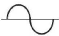 | 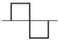 | 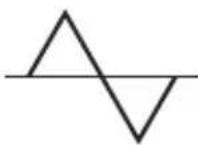 |  |
| RMS Value 100 | 100 100 100 | |||
| Average Value 90 | 100 87 64 | |||
| Crest Factor* (ξ) | 1.414 1 1.73 | 2 |
* The crest factor is the ratio of the peak value to the RMS value; it is represented by the Greek letter .
AC + DC True RMS
AC + DC true RMS calculates both of the AC and DC components given by the expression
$$ \sqrt {(A C r m s) ^ {2} + D C ^ {2}} $$
when making measurements and responds accurately to the total effective RMS value regardless of the waveform. Distorted waveforms with the presence of DC components and harmonics may cause:
• Transformers, generators, and motors to overheat
• Circuit breakers to trip prematurely
- Fuses to blow
- Neutrals to overheat due to the triplen harmonics present on the neutral
- Bus bars and electrical panels to vibrate
AC Bandwith
AC bandwidth of a digital multimeter (DMM) is the range of frequencies over which AC measurements can be made within the specified accuracy. It is the frequency response of the AC functions—not of the frequency measurement functions. A DMM cannot accurately measure the AC value with frequency spectrums beyond the AC bandwidth of the DMM. Therefore, wide AC bandwidth plays an important role in high performance DMMs. Complex waveforms, noise, and distorted waveforms contain frequency components that are much higher than the fundamental; for example, high frequency noise on a 50/60 Hz power line.
Operation

WARNING
Electric shock hazard:
Contact with live circuits could result in severe injury or death.
Self-Diagnostic Mode
The message “rE-0” may appear when the meter is turned on. This indicates that the meter is performing a routine self-diagnostic. Do not turn the meter off. Allow the diagnostic procedure to finish. If the message “C_Er” appears on the display when the meter is turned on, some ranges may be well outside of specification. To avoid incorrect measurements, stop using the meter and return it to Greenlee for recalibration.
Operating Procedure
- Refer to the Settings Table. Set the selector to the proper setting, press SELECT (when instructed to do so), and connect the test leads to the meter.
- Refer to "Typical Measurements" for specific measurement instructions.
-
Test the unit on a known functioning circuit or component.
-
If the unit does not function as expected on a known functioning circuit, replace the battery and/or fuses.
-
If the unit still does not function as expected, call Greenlee for technical assistance at 800-435-0786.
-
Take the reading from the circuit or component to be tested.
Operation (cont'd)
Settings Table
The meter stores the last used function of each selector position in its nonvolatile memory. If this is not the correct function when you turn the selector, press SELECT until the desired icon appears.
The dual display options are shown along with the icons. In the table, “\~Hz” indicates that “\~” and “V” appear in the primary display, and “Hz” appears in the secondary display. This combination shows the AC voltage measurement in the primary display and frequency in the secondary display.
| To measure this characteristic ... | Set the selector to this symbol ... | Press SELECT until these icons appear on the display ... | Connect the red lead to ... | Connect the black lead to ... |
| Variable Speed Drive—Voltage and Frequency |  |  | V - I | COM |
| Voltage—AC True RMS (1000 V max) |  |  | V - I | COM |
| *Voltage—DC (1000 V max) |  |  | V - I | COM |
| Voltage—AC + DC True RMS (1000 V max) |  | 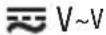 | V - I | COM |
| Voltage—DC (500 mV max) |  | 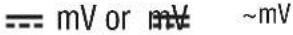 | V - I | COM |
| Voltage—AC + DC True RMS (500 mV max) |  | 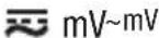 | V - I | COM |
| Voltage—AC True RMS (500 V max) |  | 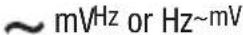 | V - I | COM |
| Frequency—Line Level Voltage or Current |  |  | — | |
| **Frequency—Logic Level | [4W63] | [CYDW] | [23C0] | COM |
| % Duty Cycle D% D% | [5X30] | COM | ||
| dBm (0 dB = 1 mW in reference impedance) | dBm( function 1000 V max; mV function 500 mV max.) | Reference impedance and dBm for 1 s, then dBm Hz (press dBm- to change reference impedance) | [1787] | COM |
* For precise measurements, press 500000 to toggle between 50,000 counts and 500,000 counts. Applies to DC volts only.
** Logic level frequency has a fixed sensitivity and is for digital signals. Refer to "Accuracy".
This table continues on the next page.
Operation (cont'd)
Settings Table (cont'd)
| To measure this characteristic ... | Set the selector to this symbol ... | Press SELECT until these icons appear on the display ... | Connect the red lead to ... | Connect the black lead to ... |
| Dual Temperature T1T2 | °C or °F (press RANGE for display options T1, T2, T1 T2 or T1-T2T2) | See Notes 1 and 2 | — | |
| †Capacitance F | -+ | ΩV -+ | COM | |
| Diode V and diod | → | ΩV -+ | COM | |
| Resistance Ω Ω | ΩV -+ | COM | ||
| Continuity | •••• | •••• and Ω | ΩV -+ | COM |
| Conductance nS nS | ΩV -+ | COM | ||
| Current—AC, DC, or AC + DC True RMS (10 A max) | A | --- A, A--- ~A, ≈ A~A, or A~Hz | A COM | |
| Current—AC, DC, or AC + DC True RMS (600 mA max) | mA | --- mA %4-20mA, --- mA~mA, ≈ mA~mA, or mA~Hz | mA μA COM | |
| Current—AC, DC, or AC + DC True RMS (6000 μA max) | μA | --- μA, μA~μA, ≈ μA~μA, or μA~Hz | mA μA COM | |
| Industrial Process Control Loop Current % 4 to 20 mA | mA | --- mA %4-20mA | mA μA COM |
† Discharge capacitor before measurement. Refer to “Typical Measurements” regarding polarized capacitors.
Note 1: T1+ connects to ΩV-+, and T1- connects to COM.
Note 2: T2+ connects to mA μA, and T2- connects to A.
Typical Measurements
Voltage Measurement
text_image
请勿使用 SELECT RANGE ADD 110.26 CREDITO RECIO DTS HV T1 + - HV A T1 2 V 2 V 2 V 30V 30V OFF A mA μA COM HV+ T1 MINT 1.2A 1.2V HANDB T1 MAX 1000ΩCurrent Measurement
text_image
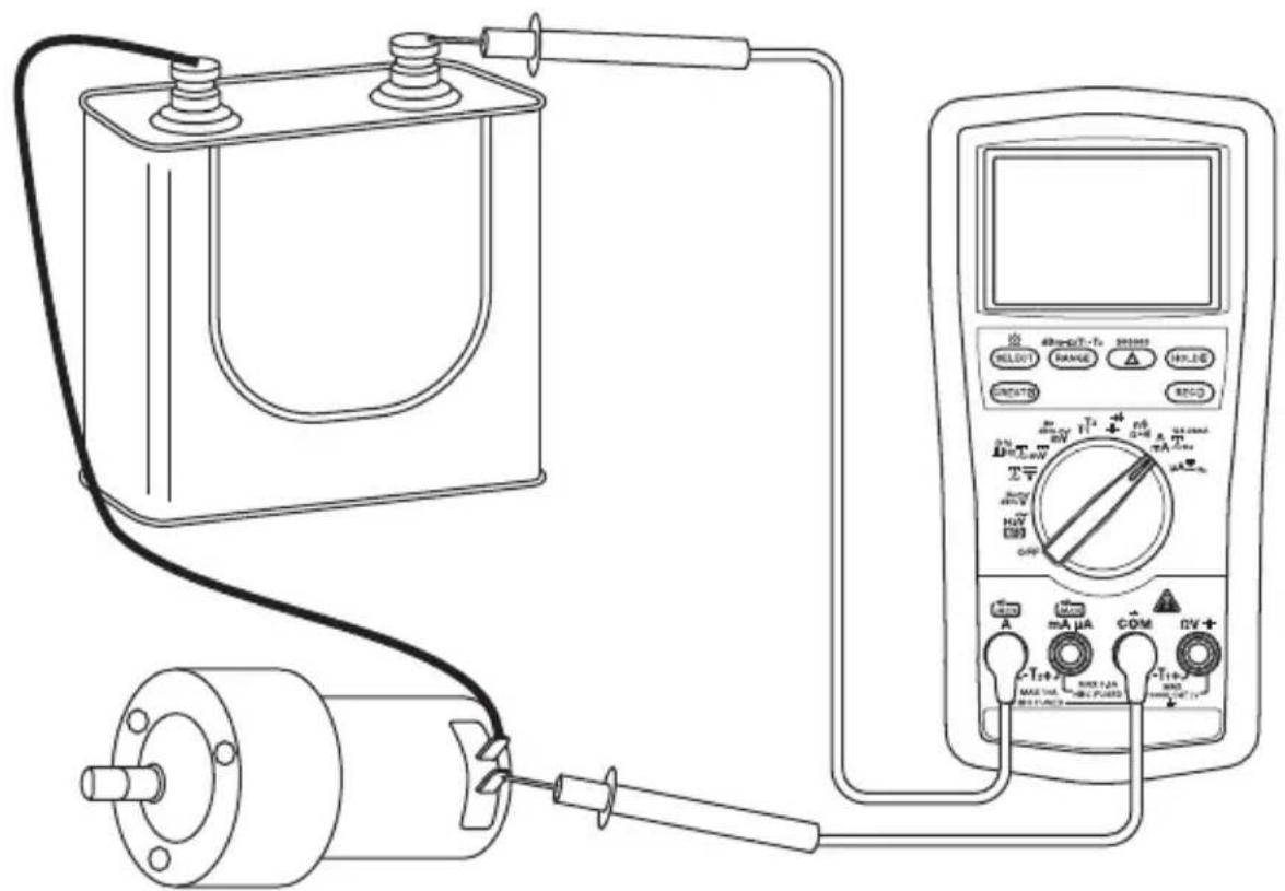
Diagram of an electrical testing setup with battery, motor, and multimeter connected to a DC power supplyTypical Measurements
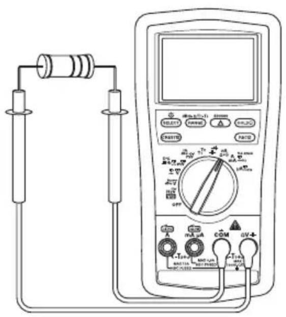
Resistance Measurement
text_image
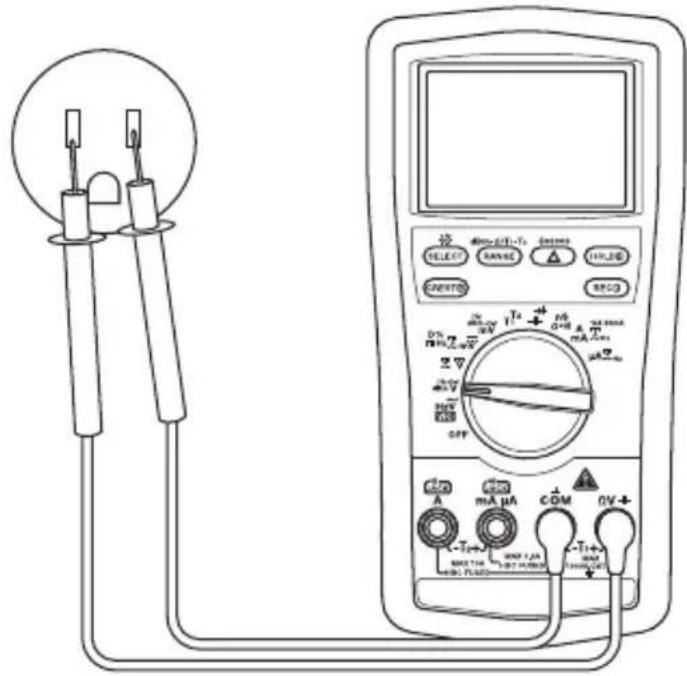
Diagram of a multimeter connected to a cylindrical battery via tubing, showing labeled components and connections.Continuity Check
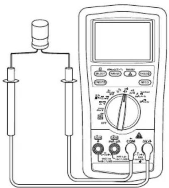
text_image
Diagram of a multimeter connected to a test tube with labeled probes and dials, showing connections and measurement ranges.Capacitance Measurement Diode Measurement
text_image
Diagram of a multimeter setup with labeled components including probe, meter, and digital display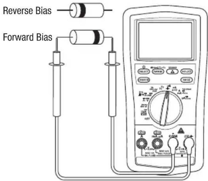
text_image
Reverse Bias Forward BiasNote: For polarized capacitors, attach red probe to positive terminal and black probe to negative terminal of capacitor.
Typical Measurements
Temperature
text_image
SELECT RANGE HOLDS RESET 3% + - 2% + - 0% + - 0% + - 0% + - 0% + - 0% + - 0% + - 0% + - 0% + - 0% + - 0% + - 0% + - 0% + - 0% + - 0% + - 0% + - 0% + - 0% + - 0% + - 0% + - 0% + - 0% + - 0% + - 0% + - 0% + - 0% + - 5% + - 5% + - 5% + - 5% + - 5% + - 5% + - 5% + - 5% + - 5% + - 5% + - 5% + - 5% + - 5% + - 5% + - 5% + - 5% + - 5% + - 5% + - 5% + - 5% + - 5% + - 5% + - 5% + - 5% + - 5% + - 0% 1+ 0% 2+ 0% 3+ 0% 4+ 0% 5+ 0% 6+ 0% 7+ 0% 8+ 0% 9+ 0% 10+ 0% 11+ 0% 12+ 0% 13+ 0% 14+ 0% 15+ 0% 16+ 0% 17+ 0% 18+ 0% 19+ 0% 20+ 0% 21+ 0% 22+ 0% 23+ 0% 24+ 0% 25+ 0% 26+ 0% 27+ 0% 28+ 0% 29+ 0% 30+ 0% 31+ 0% 32+ 0% 33+ 0% 34+ 0% 35+ 0% 36+ 0% 37+ 0% 38+ 0% 39+ 0% 40+ 0% 41+ 0% 42+ 0% 43+ 0% 44+ 0% 45+ 0% 46+ 0% 47+ 0% 48+ 0% 49+ 0% 50+ 0% 51+ 0% 52+ 0% 53+ 0% 54+ 0% 55+ 0% 56+ 0% 57+ 0% 58+ 0% 59+ 0% 60+ 0% 61+ 0% 62+ 0% 63+ 0% 64+ 0% 65+ 0% 66+ 0% 67+ 0% 68+ 0% 69+ 0% 70+ 0% 71+ 0% 72+ 0% 73+ 0% 74+ 0% 75+ 0% 76+ 0% 77+ 0% 78+ 0% 79+ 0% 80+ 0% 81+ 0% 82+ 0% 83- 0% 84- 0% 85- 0% 86- 0% 87- 0% 88- 0% 89- 0% 90- 0% 91- 0% 92- 0% 93- 0% 94- 0% 95- 0% 96- 0% 97- 0% 98- 0% 99- 1 MAX: THI MAX: FLAME MAX: FLAME MAX: FLAME MAX: FLAME MAX: FLAME MAX: FLAME MAX: FLAME MAX: FLAME MAX: FLAME MAX: FLAME MAX: FLAME MAX: FLAME MAX: FLAME MAX: FLAME MAX: FLAME MAX: FLAME MAX: FLAME MAX: FLAME MAX: FLAME MAX: FLAME MAX: FLAM MAX: FLAM MAX: FLAM MAX: FLAM MAX: FLAM MAX: FLAM MAX: FLAM MAX: FLAM MAX: FLAM MAX: FLAM MAX: FLAM MAX: FLAM MAX: FLAM MAX: FLAM MAX: FLAM MAX: FLAM MAX: FLAM MAX: FLAM MAX: FLAM MAX: FLAM MAX: FLA MAX: FLA MAX: FLA MAX: FLA MAX: FLA MAX: FLA MAX: FLA MAX: FLA MAX: FLA MAX: FLA MAX: FLA MAX: FLA MAX: FLA MAX: FLA MAX: FLA MAX: FLA MAX: FLA MAX: FLA MAX: FLA MAX: FLA MAX: FLF MAX: FLF MAX: FLF MAX: FLF MAX: FLF MAX: FLF MAX: FLF MAX: FLF MAX: FLF MAX: FLF MAX: FLF MAX: FLF MAX: FLF MAX: FLF MAX: FLF MAX: FLF MAX: FLF MAX: FLF MAX: FLF MAX: FLF MAX: FLM MAX: FLM MAX: FLM MAX: FLM MAX: FLM MAX: FLM MAX: FLM MAX: FLM MAX: FLM MAX: FLM MAX: FLM MAX: FLM MAX: FLM MAX: FLM MAX: FLM MAX: FLMUsing the Optional Software
The DM-860A is compatible with Greenlee DMSC-9U, an optically isolated computer interface cable and software. It allows measurements to be logged to a personal computer using the Microsoft® Windows® operating system.
Installing the Software
- Insert the CD into the computer's CDROM drive.
- The installation program should launch automatically. If it does not, double click on the CD icon in "My Computer."
- The installation program menu will appear. Click on "Software Installation."
- Type your meter's catalog number (for example, "DM-860A") in the dialog box.
- Complete the remaining dialog boxes according to user preferences.
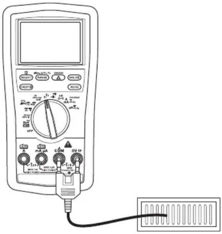
Connecting the Optical USB Interface Cable
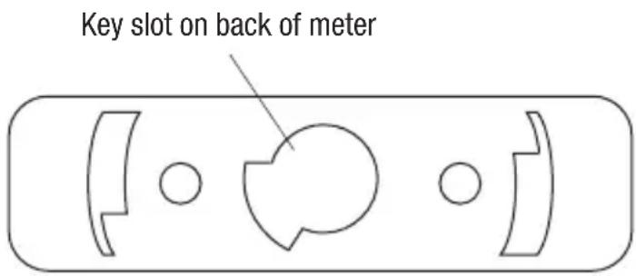
- Align the key of the connector with the key slot on the meter.
- Twist the connector clockwise until it locks into place.
- Connect the cable to a USB port of the PC.
text_image
Key slot on back of meterAccuracy
Refer to the “Specifications” section for operating conditions and temperature coefficient.
Accuracy is specified as follows: ± (a percentage of the reading + a fixed amount) at 23 °C ± 5 °C (73.4 °F ± 9 °F), 0% to 75% relative humidity. Specifications are for 50,000 counts mode.
True RMS Readings: Voltage and current accuracies are specified from 5% to 100% of the range unless otherwise specified. Frequency must be within the specified bandwidth for non-sinusoidal waveforms. Crest factors are as follows:
- Crest factor < 2.1 : 1 at full scale
- Crest factor < 4.2 : 1 at half scale
AC, DC ^AC , and AC + DC ^AC Current
| Range | Accuracy at DC and 50 Hz to 60 Hz | Accuracy at 40 Hz to 1 kHz | Accuracy at 1 kHz to 20 kHz | Accuracy at 20 kHz to 100 kHz |
| 500.00 μA ± | (0.5% + 0.5 μA) ± (0.7% + 0.5 μA) ± (2.0% | + 0.5 μA) ± (5.0% + 0.5 μA) | ||
| 5000.0 μA ± | (0.5% + 5.0 μA) ± (0.7% + 5.0 μA) ± (2.0% | + 5.0 μA) ± (5.0% + 5.0 μA) | ||
| 50.000 mA ± | (0.5% + 0.05 mA) ± | (0.7% + 0.05 mA) ± (2.0% + 0.05 mA) ± (5.0% + 0.05 mA) | ||
| 500.00 mA ± | (0.5% + 0.5 mA) ± (0.7% + 0.5 mA) ± (2.0% + 0.5 mA) ± (5.0% + 0.5 mA) | |||
| 5.0000 A ± | (0.5% + 0.005 A) ± (0.7% + 0.005 A) Unspecified Unspecified | |||
| 10.000 A* ± | (0.5% + 0.05 A) ± (0.7% + 0.05 A) Unspecified Unspecified |
*10 A continuous; 20 A maximum (Duty Cycle: 30 seconds on, 5 minutes off).
| Range | Burden Voltage(all frequency ranges) |
| 500.00 μA | 0.15 mV/μA |
| 5000.0 μA | |
| 50.000 mA | 3.3 mV/mA |
| 500.00 mA | |
| 5.0000 A | 45 mV/A |
| 10.000 A |
DC Current
| Range Accuracy Burden Voltage | ||
| 500.00 μA ± | (0.15% + 0.2 μA) | 0.15 mV/μA |
| 5000.0 μA ± | (0.1% + 2.0 μA) | |
| 50.000 mA ± | (0.15% + 0.02 mA) | 3.3 mV/mA |
| 500.00 mA ± | (0.15% + 0.3 mA) | |
| 5.0000 A | ± (0.5% + 0.002 A) | 45 mV/A |
| 10.000 A* | ± (0.5% + 0.02 A) | |
*10 A continuous; 20 A maximum (Duty Cycle: 30 seconds on, 5 minutes off).
Accuracy (cont'd)
DC ^AC and AC + DC ^AC Voltage
| Range | Accuracy* at 20 Hz to 45 Hz | Accuracy* at DC and 45 Hz to 1 kHz | Accuracy* at 1 kHz to 20 kHz | Accuracy* at 20 kHz to 40 kHz |
| 500.00 mV ± (1.5% + 0.4 mV) ± (0.5% + 0.4 mV) ± (1.0% + 0.4 mV) ± (3.5% + 0.4 mV)** | ||||
| 5.0000 V ± (1.5% + 0.004 V) ± (0.5% + 0.008 V) ± (1.2% + 0.004 V) ± (4.0% + 0.004 V)** | ||||
| 50.000 V ± (1.5% + 0.04 V) ± (0.5% + 0.08 V) ± (1.2% + 0.04 V) ± (4.0% + 0.04 V)** | ||||
| 500.00 V Unspecified ± (0.5% + 0.8 V) Unspecified Unspecified | ||||
| 1000.0 V Unspecified ± (0.5% + 8 V) Unspecified Unspecified | ||||
*From 5% to 10% of range: Accuracy percentage of reading + 80 digits.
** From 5% to 10% of range: Accuracy percentage of reading + 180 digits.
From 10% to 15% of range: Accuracy percentage of reading + 100 digits.
Residual reading less than 50 digits with test leads shorted.
Note: “Digits” refers to the least significant digit (the number in the right-most position).
VFD AC Voltage
| Range | Accuracy* at 5 Hz to 20 Hz | Accuracy* at 20 Hz to 200 Hz | Accuracy* at 200 Hz to 440 Hz |
| 5.0000 V ± (3 % + 0.008 V) ± (2% + 0.005 V) ± (6% + 0.008 V)** | |||
| 50.000 V ± (3 % + 0.08 V) ± (2% + 0.05 V) ± (6% + 0.08 V)** | |||
| 500.00 V ± (3 % + 0.8 V) ± (2% + 0.5 V) ± (6% + 0.8 V)** | |||
| 1000.0 V ± (3% + 8 V) ± (2% + 5 V) ± (6% + 8 V)** |
*Not specified for fundamental frequency greater than 440 Hz.
**Accuracy decreases linearly from ± (2.0% + 50 digits) at 200 Hz to ± (6% + 80 digits) at 440 Hz.
Accuracy (cont'd)
AC Voltage
| Range | Accuracy* at 20 Hz to 45 Hz | Accuracy* at 45 Hz to 65 Hz | Accuracy* at 65 Hz to 10 kHz |
| 500.00 mV ± | (1.2% + 0.4 mV) ± (0.3% + 0.2 mV) ± (0.4% + 0.25 mV) | ||
| 5.0000 V ± (1 | 2% + 0.004 V) ± (0.3% + 0.003 V) ± (0.3% + 0.004 V) | ||
| 50.000 V ± (1 | 2% + 0.04 V) ± (0.3% + 0.03 V) ± (0.3% + 0.04 V) | ||
| 500.00 V Unspecified ± (0.5% + 0.3 V) ± (0.5% + 0.4 V) | |||
| 1000.0 V Unspecified ± (0.5% + 3 V) ± (0.8% + 4 V) (65 Hz to 1 kHz) | |||
| Range | Accuracy* at 10 kHz to 20 kHz | Accuracy* at 20 kHz to 100 kHz |
| 500.00 mV ± | (0.5% + 0.3 mV) ± (2.5% + 0.4 mV)** | |
| 5.0000 V ± (0 | 7% + 0.004 V) ± (3.5% + 0.004 V)** | |
| 50.000 V ± (0 | 7% + 0.04 V) ± (3.5% + 0.04 V)** | |
| 500.00 V ± (0 | 7% + 0.4 V) Unspecified | |
| 1000.0 V Unspecified Unspecified | ||
*From 5% to 10% of range: Accuracy percentage of reading + 80 digits.
** From 5% to 10% of range: Accuracy percentage of reading + 180 digits.
Residual reading less than 50 digits with test leads shorted.
Note: “Digits” refers to the least significant digit (the number in the right-most position).
DC Voltage
| Range Accuracy | Input Impedance | |
| 500.00 mV ± | (0.02% + 0.02 mV) | 10 MΩ, 80 pF nominal |
| 5.0000 V | ± (0.02% + 0.0002 V) | 10 MΩ, 60 pF nominal |
| 50.000 V | ± (0.03% + 0.002 V) | |
| 500.00 V | ± (0.04% + 0.02 V) | |
| 1000.0 V | ± (0.15% + 0.2 V) | |
Accuracy (cont'd)
Resistance and Conductance
| Range Accuracy | Typical Open Circuit Voltage |
| 500.00 Ω ± (0.07% + 0.10 Ω) 3.0 VDC | |
| 5.0000 kΩ ± (0.07% + 0.0002 kΩ) | 1.3 VDC |
| 50.000 kΩ ± (0.1% + 0.002 kΩ) | |
| 500.00 kΩ ± (0.1% + 0.02 kΩ) | |
| 5.0000 MΩ ± (0.3% + 0.0006 MΩ) | |
| 50.000 MΩ ± (2.0% + 0.006 MΩ) | |
| 99.99 nS ± (0.8% + 0.10 nS)* |
* ± (2.0% + 0.40 nS) below 9.99 nS.
Capacitance
| Range Accuracy* | |
| 50.00 nF ± (0) | 8% + 0.03 nF) |
| 500.0 nF ± (0) | 8% + 0.3 nF) |
| 5.000 μF ± (1) | 5% + 0.003 μF) |
| 50.00 μF ± (2) | 5% + 0.03 μF) |
| 500.0 μF** ± | (3.5% + 0.5 μF) |
| 5.000 mF** ± | (5.0% + 0.005 mF) |
| 25.00 mF** ± | (6.5% + 0.05 mF) |
*Accuracies are for film capacitors (capacitors with negligible dielectric absorption).
** In manual ranging mode, the 500.0 μF, 5.000 mF, and 25.00 mF ranges are not specified below 45.0 μF, 0.450 mF, and 4.50 mF, respectively.
T1, T2, T1-T2 Dual Temperature
| Range Accuracy* | |
| -50 °C to 1000.0 °C ± | (0.3% + 1.5 °C) |
| -58 °F to 1832.0 °F ± | (0.3% + 3.0 °F) |
*Thermocouple range and accuracy not included.
Accuracy (cont'd)
Frequency—Line Level
Range: 5.000 Hz to 200.00 kHz
Accuracy: ± (0.02% + 4 digits)
| AC Function Range | Sensitivity (Sine RMS) | Range |
| 500 mV 100 | mV | 10 Hz to 200 kHz |
| 5 V 0.5 V 500 | 00 μA 500 μA | |
| 50 V 5 V | 10 Hz to 100 kHz | |
| 500 V 50 V 5 | 00 mA 50 mA | |
| 1000 V 500 V | 10 Hz to 10 kHz | 5 A 1 A |
| VFD 5 V 0.5 V | to 2 V* | 10 Hz to 440 Hz |
| VFD 50 V | 5 V to 20 V* | |
| VFD 500 V | 50 V to 200 V* |
| AC Function Range | Sensitivity (Sine RMS) | Range |
| 500 μA 50 | μA | 10 Hz to 10 kHz |
| 50 mA 5 mA | ||
| 10 Hz to 3 kHz | ||
| 10 A | 10 A |
*VFD sensitivity linearly decreases from 10% of range @ 200 Hz to 40% of range @ 440 Hz.
Frequency—Logic Level
Range: 5.000 Hz to 2.0000 MHz
Accuracy: ± (0.002% + 4 digits)
Sensitivity: 2.5 Vp square wave
% Duty Cycle
Range: 0.1% to 99.99%
Accuracy: ± (3 digits/kHz + 2 digits)
Input Frequency: 5 Hz to 500 kHz, 5 V logic family
Diode Test
Measuring Range: 2.0000 V
Test Current (typical): 0.4 mA
Open Circuit Voltage: < 3.0 VDC
Accuracy: ± (1% + 0.0001 V)
Continuity
Tone Threshold: Between 20 Ω and 200 Ω
Response Time: < 100 μs
dBm
The range and accuracy depend on the AC voltage function used and the selected reference impedance.
Selectable Reference Impedance: 4, 8, 16, 32, 50, 75, 93, 110, 125, 135, 150, 200, 250, 300, 500, 600, 800, 900, 1000, 1200 Ω
Crest Capture (Voltage and Current) for Crests > 0.8 ms in duration
Accuracy: Specified accuracy ± 100 digits
Resolution: 5000 digits
Specifications
Display: LCD
Normal Mode: 50,000 counts
High Resolution Mode: 500,000 counts
Frequency: 99,999 counts
41-segment bar graph
Polarity: Automatic
Input Impedance: 10 MΩ, 60 pF nominal (80 pF for 500 mV ranges).
Sampling Rate:
50,000 Counts Mode: 5 per second nominal
500,000 Counts Mode: 1.25 per second nominal
Bar Graph Display: 60 per second
Temperature Coefficient: Nominal 0.15 x (Accuracy) per °C below 18 °C from 0 °C to 18 °C
(32 °F to 64 °F) or above 28 °C from 28 °C to 40 °C (82 °F to 104 °F) or otherwise specified
Intelligent Automatic Power Off: After 17 minutes of inactivity
Low Battery Indication: Below approximately 7 V
Noise Rejection*:
Normal Mode Rejection Ratio > 60 dB at 50 Hz and 60 Hz when measuring DCV
Common Mode Rejection Ratio > 90 dB from 0 Hz to 60 Hz when measuring ACV
Common Mode Rejection Ratio > 120 dB at 50 Hz and 60 Hz when measuring DCV
Operating Conditions:
0 °C to 31 °C (32 °F to 88 °F), 0% to 80% relative humidity
31 °C to 45 °C (88 °F to 113 °F), relative humidity decreasing linearly from 80% to 50% (non-condensing)
Altitude: 2000 m (6500') maximum
Indoor use only
Pollution Degree: 2
Storage Conditions: -20^ to 60^ (-4^ to 140^) , 0% to 80% relative humidity (non-condensing)
Remove battery
Battery: 9 V battery (NEDA 1604, JIS 006P or IEC 6F)
E.M.C.: Meets EN61326-1:2006
In an RF field of 3 V/m:
Capacitance function is not specified
Other function ranges: Total Accuracy = Specified Accuracy + 1000 digits
Performance above 3 V/m is not specified
* Noise rejection is the ability to reject unwanted signals, or noise.
- Normal mode voltages are AC signals that can cause inaccurate DC measurements. NMRR (Normal Mode Rejection Ratio) is a measure of the ability to filter out these signals.
- Common mode voltages are signals present at the COM and + input terminals, with respect to ground, that can cause digit rattle or offset in voltage measurements. CMRR (Common Mode Rejection Ratio) is a measure of the ability to filter out these signals.
Specifications (cont'd)
Safety: Double insulation per IEC/UL/EN61010-1 Ed. 3.0, IEC/EN61010-2-030 Ed. 1.0, IEC/EN61010-2-033 Ed. 1.0, IEC/UL/EN61010-031 Ed. 1.1 and CAN/CSA-C22.2 No. 61010-1-12 Ed. 3.0 to Category IV 1000 V AC/DC.
Overload Protections:
V: 1100 V DC/AC rms
A: 11 A/1000 V fuse, interrupting rating 20 kA, F fuse, 13/32" x 1-1/2"
μA and mA: 0.44 A/1000 V fuse, interrupting rating 10 kA, F fuse, 13/32" x 1-3/8"
mV, Ω, and Other Functions: 1000 V DC/AC rms
CENELEC DIRECTIVES: The instruments conform to CENELEC Low-voltage directive 2006/95/EC and Electromagnetic compatibility directive 2004/108/EC
Measurement Categories
These definitions were derived from the international safety standard for insulation coordination as it applies to measurement, control, and laboratory equipment. These measurement categories are explained in more detail by the International Electrotechnical Commission; refer to either of their publications: IEC 61010-1 or IEC 60664.
Measurement Category I
Signal level. Electronic and telecommunication equipment, or parts thereof. Some examples include transient-protected electronic circuits inside photocopiers and modems.
Measurement Category II
Local level. Appliances, portable equipment, and the circuits they are plugged into. Some examples include light fixtures, televisions, and long branch circuits.
Measurement Category III
Distribution level. Permanently installed machines and the circuits they are hard-wired to. Some examples include conveyor systems and the main circuit breaker panels of a building's electrical system.
Measurement Category IV
Primary supply level. Overhead lines and other cable systems. Some examples include cables, meters, transformers, and other exterior equipment owned by the power utility.
Statement of Conformity
Greenlee Tools, Inc. is certified in accordance with ISO 9001:2008 for our Quality Management Systems.
The instrument enclosed has been checked and/or calibrated using equipment that is traceable to the National Institute for Standards and Technology (NIST).
Maintenance
WARNING
Electric shock hazard:
Before opening the case, remove the test leads from the circuit and shut off the unit.
Failure to observe these warnings could result in severe injury or death.
WARNING
Electric shock hazard:
The fuses are an integral part of the overvoltage protection. When fuse replacement is necessary, refer to “Specifications” for the correct type, size, and capacity. Using any other type of fuse will void the overvoltage protection rating of the unit.
Failure to observe this warning could result in severe injury or death.
Replacing the Battery
- Disconnect the unit from the circuit. Turn the unit OFF.
- Remove the two screws from the battery access door and remove it.
- Replace the battery making sure to observe the polarity.
Replacing the Fuses
- Disconnect the unit from the circuit. Turn the unit OFF.
- Remove the two screws from the battery access door and remove it.
- Unscrew the two screws inside the battery compartment and the two screws on the back case.
- Remove the back cover and replace the fuses.
- Align the two halves of the unit and the rubber gaskets.
-
Replace the cover and screws.
-
Be sure the selector is in the original position so that it lines up properly with the internal switch.
natural_image
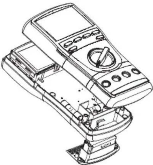
Technical line drawing of a mechanical device with control panel and base mount (no text or symbols)Cleaning and Storage
Periodically wipe the case with a damp cloth and mild detergent; do not use abrasives or solvents.
If the meter will not to be used for periods longer than 60 days, remove the battery and store it separately.
Descripción
natural_image
Illustration of a hand interacting with a closed book (no text or symbols visible)ADVERTENCIA
text_image
Technical diagram showing a DC motor connected to a multimeter via tubing, with labeled components and measurement ranges.text_image
Diagram of a multimeter connected to two cylindrical sensors, showing labeled components and wiring connections.text_image
Diagram of a multimeter connected to a test tube with labeled probes and dials, showing connections and measurement ranges.text_image
Diagram of a multimeter connected to a cylindrical device with labeled components and measurement scales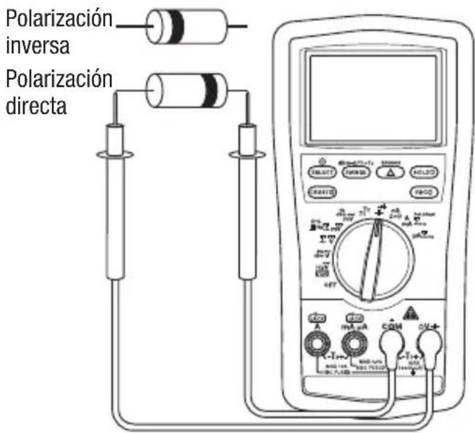
text_image
SELECT ARRAY HOLD RESET 3V HV HV OFF mA μA CDM DV 1+ MAX TIME MAX FLOW MAX FLOW MAX FLOW MAX FLOW MAX FLOW MAX FLOW MAX FLOW MAX FLOW MAX FLOW MAX FLOW MAX FLOW MAX FLOW MAX FLOWnatural_image
Pure diagram of three abstract shapes inside a rounded rectangle, no text or symbols presentExactitud
natural_image
Technical line drawing of a mechanical device with control panel and base mount (no text or symbols)natural_image
Illustration of a hand interacting with an open book (no text or symbols visible)▲AVERTISSEMENT
text_image
Diagram of an electrical testing setup with battery, motor, and multimeter connected to a DC power supplyMesures types
text_image
Diagram of a multimeter connected to a cylindrical battery via tubing, showing labeled components and connections.text_image
Diagram of a multimeter connected to a test tube with labeled probes and dials, showing connections and function labels.text_image
Diagram of a multimeter setup with labeled components including probe, meter, and display screen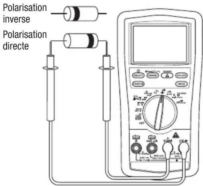
text_image
Polarisation inverse Polarisation directenatural_image
Pure diagram of three abstract shapes inside a rounded rectangle, no text or symbols presentPrécision
natural_image
Technical line drawing of a handheld electronic device with control panel and display (no text or symbols)Lifetime Limited Warranty
Greenlee Tools, Inc. warrants to the original purchaser of these goods for use that these products will be free from defects in workmanship and material for their useful life, excepting normal wear and abuse. This warranty is subject to the same terms and conditions contained in Greenlee Tools, Inc.'s standard one-year limited warranty.
For all Test Instrument repairs, contact Customer Service at 800-435-0786 and request a Return Authorization.
For items not covered under warranty (such as items dropped, abused, etc.), a repair cost quote is available upon request.
Note: Prior to returning any test instrument, please check replaceable batteries or make sure the battery is at full charge.
An ISO 9001 Company • ©2019 Greenlee Tools, Inc.
USA
Tel: 800-435-0786
Fax: 800-451-2632
Canada
Tel: 800-435-0786
Fax: 800-524-2853
International
Tel: +1-815-397-7070
Fax: +1-815-397-9247