6842J - Screwdriver MAKITA - Free user manual and instructions
Find the device manual for free 6842J MAKITA in PDF.
Download the instructions for your Screwdriver in PDF format for free! Find your manual 6842J - MAKITA and take your electronic device back in hand. On this page are published all the documents necessary for the use of your device. 6842J by MAKITA.
USER MANUAL 6842J MAKITA
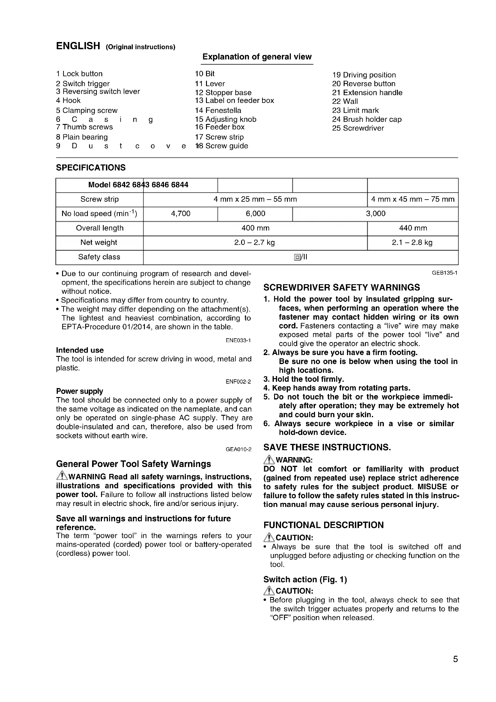
- Due to our continuing program of research and devel- opment, the specifications herein are subject to change without notice.
- Specifications may differ from country to country.
- The weight may differ depending on the attachment(s). The lightest and heaviest combination, according to EPTA-Procedure 01/2014, are shown in the table. ENE033-1 Intended use The tool is intended for screw driving in wood, metal and plastic. ENF002-2 Power supply The tool should be connected only to a power supply of the same voltage as indicated on the nameplate, and can only be operated on single-phase AC supply. They are double-insulated and can, therefore, also be used from sockets without earth wire. GEA010-2 General Power Tool Safety Warnings WARNING Read all safety warnings, instructions, illustrations and specifications provided with this power tool. Failure to follow all instructions listed below may result in electric shock, fire and/or serious injury. Save all warnings and instructions for future reference. The term “power tool” in the warnings refers to your mains-operated (corded) power tool or battery-operated (cordless) power tool. GEB135-1
SCREWDRIVER SAFETY WARNINGS
1. Hold the power tool by insulated gripping sur-
faces, when performing an operation where the fastener may contact hidden wiring or its own cord. Fasteners contacting a “live” wire may make exposed metal parts of the power tool “live” and could give the operator an electric shock.
2. Always be sure you have a firm footing.
Be sure no one is below when using the tool in high locations.
3. Hold the tool firmly.
4. Keep hands away from rotating parts.
5. Do not touch the bit or the workpiece immedi-
ately after operation; they may be extremely hot and could burn your skin.
6. Always secure workpiece in a vise or similar
hold-down device. SAVE THESE INSTRUCTIONS.
DO NOT let comfort or familiarity with product (gained from repeated use) replace strict adherence to safety rules for the subject product. MISUSE or failure to follow the safety rules stated in this instruc- tion manual may cause serious personal injury. FUNCTIONAL DESCRIPTION CAUTION:
- Always be sure that the tool is switched off and unplugged before adjusting or checking function on the tool. Switch action (Fig. 1) CAUTION:
- Before plugging in the tool, always check to see that the switch trigger actuates properly and returns to the “OFF” position when released. Model 6842 6843 6846 6844 Screw strip 4 mm x 25 mm – 55 mm 4 mm x 45 mm – 75 mm No load speed (min
) 4,700 6,000 3,000 Overall length 400 mm 440 mm Net weight 2.0 – 2.7 kg 2.1 – 2.8 kg Safety class /II6 To start the tool, simply pull the switch trigger. Release the switch trigger to stop. For continuous operation, pull the switch trigger and then push in the lock button. To stop the tool from the locked position, pull the switch trigger fully, then release it. Reversing switch action (Fig. 2) This tool has a reversing switch to change the direction of rotation. Depress the reversing switch lever from the A side for clockwise rotation or from the B side for counter- clockwise rotation. CAUTION:
- Always check the direction of rotation before operation.
- Use the reversing switch only after the tool comes to a complete stop. Changing the direction of rotation before the tool stops may damage the tool. Hook (Fig. 3) The hook is convenient for hooking the tool to your belt. It can be installed on either side of the tool. Changing the installation position of hook allows two-way setting of 10 mm and 20 mm distance from the tool itself. The tool with hook can be hung on the waist belt, a maxi- mum diameter 20 mm pipe etc. To remove the hook, just remove the clamping screw. Place it on the tool and secure it with the clamping screw to install. ASSEMBLY CAUTION:
- Always be sure that the tool is switched off and unplugged before carrying out any work on the tool. Installing or removing the bit (Fig. 4 & 5) Loosen the thumb screws which secure the casing. Pull out the casing in the direction of the arrow. Press the dust cover toward the plain bearing and pull out the bit. If the dust cover cannot be moved as far as the plain bearing, try it again after turning the bit slightly. To install the bit, insert it into the socket while turning it slightly. After installing, always make sure that the bit is securely held in place by trying to pull it out. Setting for desired screw length (Fig. 6) There are 7 positive-lock screw length settings. To obtain the desired setting, pull out the stopper base while depressing the lever until you see the number of the desired screw length (indicated on the label on feeder box) appear to rest in the fenestella of stopper base. See the table below for the relation between the number indi- cated on the label on feeder box and the respective screw length. For Models 6842, 6843, 6846 For Model 6844 Adjusting the driving depth (Fig. 7) Depress the stopper base as far as it will go. While keep- ing it in this position, turn the adjusting knob until the bit tip projects approx. 5 mm from the stopper base. Drive a trial screw. If the screw head projects above the surface of the workpiece, turn the adjusting knob in the “A” direc- tion; if the screw head is counter-sunk, turn the adjusting knob in the “B” direction. Installing screw strip (Fig. 8 & 9) Insert the screw strip through the screw guide. Then insert it through the feeder box until the first screw reaches the position next to the driving position. Removing screw strip (Fig. 10 & 11) To remove the screw strip, just pull it out in the direction of the arrow. If you depress the reverse button, you can pull out the screw strip in the reverse direction of the arrow. Folding screw guide (Fig. 12) Screw guide is foldable. Folding the screw guide allows space used for storage to be minimal. Extension handle (optional accessory) (Fig. 13) Use of extension handle allows you to drive screws into floors while standing. OPERATION Driving operation (Fig. 14) Switch on the tool by pressing the switch trigger and at the same time pushing the lock button. Hold the tool squarely against the workpiece and apply forward pres- sure to the tool. The screw will be automatically carried to the driving position and driven into the workpiece. CAUTION:
- Always hold the tool squarely against the driving sur- face. Holding it at an angle may damage the screw heads and cause wear on the bit. This may also lead to poor fastening.
- Always keep the tool firmly against the driving surface until the driving is over. Failure to do so may cause insufficient fastening of screws.
- Be careful not to drive a screw onto another screw already fastened.
- Do not operate the tool without screws. It will damage the driving surface. Number indicated on the label Screw length 25 25 mm 30 30 mm 35 35 mm 40 40 mm 45 45 mm 50 50 mm 55 55 mm Number indicated on the label Screw length 45 45 mm 50 50 mm 55 55 mm 60 60 mm 65 65 mm 70 70 mm 75 75 mm7 Driving in corner (Fig. 15) This tool can be used to drive at a position 15 mm away from the wall as shown in Fig. 15. CAUTION:
- Driving at a position closer than 15 mm to the wall or driving with the stopper base in contact with the wall may damage the screw heads and cause wear on the bit. This may also lead to poor fastening of screws and malfunction of the tool. MAINTENANCE CAUTION:
- Always be sure that the tool is switched off and unplugged before attempting to perform inspection or maintenance.
- Never use gasoline, benzine, thinner, alcohol or the like. Discoloration, deformation or cracks may result. Replacing carbon brushes Remove and check the carbon brushes regularly. Replace when they wear down to the limit mark. Keep the carbon brushes clean and free to slip in the holders. Both carbon brushes should be replaced at the same time. Use only identical carbon brushes. (Fig. 16) Use a screwdriver to remove the brush holder caps. Take out the worn carbon brushes, insert the new ones and secure the brush holder caps. (Fig. 17) To maintain product SAFETY and RELIABILITY, repairs, any other maintenance or adjustment should be per- formed by Makita Authorized Service Centers, always using Makita replacement parts. OPTIONAL ACCESSORIES CAUTION:
- These accessories or attachments are recommended for use with your Makita tool specified in this manual. The use of any other accessories or attachments might present a risk of injury to persons. Only use accessory or attachment for its stated purpose. If you need any assistance for more details regarding these accessories, ask your local Makita Service Center.
- Plastic carrying case NOTE:
- Some items in the list may be included in the tool pack- age as standard accessories. They may differ from country to country. ENG905-1 Noise The typical A-weighted noise level determined according to EN62841: Model 6842, 6843 Sound pressure level (L
): 84 dB (A) Sound power level (L
): 85 dB (A) Sound power level (L
- The declared noise emission value(s) has been mea- sured in accordance with a standard test method and may be used for comparing one tool with another.
- The declared noise emission value(s) may also be used in a preliminary assessment of exposure.
- Wear ear protection.
- The noise emission during actual use of the power tool can differ from the declared value(s) depend- ing on the ways in which the tool is used especially what kind of workpiece is processed.
- Be sure to identify safety measures to protect the operator that are based on an estimation of expo- sure in the actual conditions of use (taking account of all parts of the operating cycle such as the times when the tool is switched off and when it is running idle in addition to the trigger time). ENG900-1 Vibration The vibration total value (tri-axial vector sum) determined according to EN62841: Work mode: screwdriving without impact Vibration emission (a
- The declared vibration total value(s) has been mea- sured in accordance with a standard test method and may be used for comparing one tool with another.
- The declared vibration total value(s) may also be used in a preliminary assessment of exposure.
- The vibration emission during actual use of the power tool can differ from the declared value(s) depending on the ways in which the tool is used especially what kind of workpiece is processed.
- Be sure to identify safety measures to protect the operator that are based on an estimation of expo- sure in the actual conditions of use (taking account of all parts of the operating cycle such as the times when the tool is switched off and when it is running idle in addition to the trigger time).
EC DECLARATION OF CONFORMITY
- Plastic draagkoffer OPMERKING: