DTW285RTJ - Screwdriver MAKITA - Free user manual and instructions
Find the device manual for free DTW285RTJ MAKITA in PDF.
Download the instructions for your Screwdriver in PDF format for free! Find your manual DTW285RTJ - MAKITA and take your electronic device back in hand. On this page are published all the documents necessary for the use of your device. DTW285RTJ by MAKITA.
USER MANUAL DTW285RTJ MAKITA
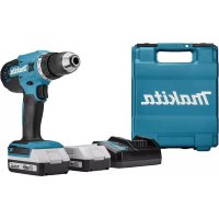
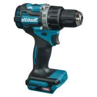
Cordless Impact Wrench INSTRUCTION MANUAL 4
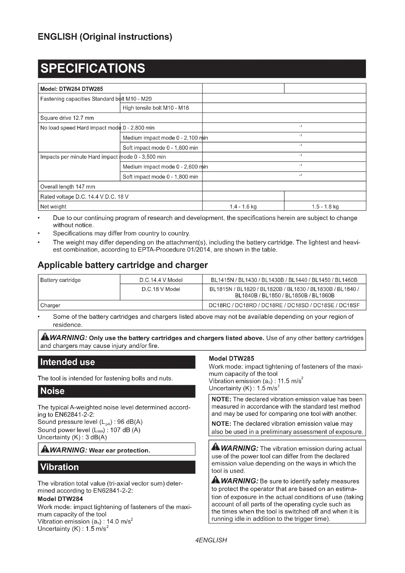
- Specicationsmaydifferfromcountrytocountry.
- Theweightmaydifferdependingontheattachment(s),includingthebatterycartridge.Thelightestandheavi- est combination, according to EPTA-Procedure 01/2014, are shown in the table. Applicable battery cartridge and charger Batterycartridge D.C.14.4 V Model BL1415N / BL1430 / BL1430B / BL1440 / BL1450 / BL1460B D.C.18 V Model BL1815N / BL1820 / BL1820B / BL1830 / BL1830B / BL1840 / BL1840B / BL1850 / BL1850B / BL1860B Charger DC18RC / DC18RD / DC18RE / DC18SD / DC18SE / DC18SF
- Someofthebatterycartridgesandchargerslistedabovemaynotbeavailabledependingonyourregionof residence.
WARNING: Only use the battery cartridges and chargers listed above.Useofanyotherbatterycartridges
WARNING: Wear ear protection.
NOTE: The declared vibration emission value has been measured in accordance with the standard test method andmaybeusedforcomparingonetoolwithanother. NOTE: Thedeclaredvibrationemissionvaluemay alsobeusedinapreliminaryassessmentofexposure.
WARNING: The vibration emission during actual
use of the power tool can differ from the declared emissionvaluedependingonthewaysinwhichthe tool is used.
WARNING:Besuretoidentifysafetymeasures
to protect the operator that are based on an estima- tionofexposureintheactualconditionsofuse(taking accountofallpartsoftheoperatingcyclesuchas the times when the tool is switched off and when it is runningidleinadditiontothetriggertime).5 ENGLISH EC Declaration of Conformity For European countries only TheECdeclarationofconformityisincludedasAnnexA to this instruction manual. SAFETY WARNINGS General power tool safety warnings
Read all safety warnings, instruc- tions, illustrations and specications provided with this power tool. Failure to follow all instructions listed below mayresultinelectricshock,reand/orseriousinjury. Save all warnings and instruc- tions for future reference. Theterm"powertool"inthewarningsreferstoyour mains-operated(corded)powertoolorbattery-operated (cordless)powertool. Cordless impact wrench safety warnings
1. Hold the power tool by insulated gripping
surfaces, when performing an operation where the fastener may contact hidden wiring. Fastenerscontactinga"live"wiremaymake exposedmetalpartsofthepowertool"live"and could give the operator an electric shock.
2. Wear ear protectors.
3. Check the impact socket carefully for wear,
cracks or damage before installation.
4. Hold the tool rmly.
5. Keep hands away from rotating parts.
6. Always be sure you have a rm footing.
Be sure no one is below when using the tool in high locations.
7. The proper fastening torque may differ
depending upon the kind or size of the bolt. Check the torque with a torque wrench. SAVE THESE INSTRUCTIONS.
DO NOT let comfort or familiarity with product (gained from repeated use) replace strict adherence to safety rules for the subject product. MISUSE or failure to follow the safety rules stated in this instruction manual may cause serious personal injury. Important safety instructions for battery cartridge
Before using battery cartridge, read all instruc- tions and cautionary markings on (1) battery charger, (2) battery, and (3) product using battery.
2. Do not disassemble battery cartridge.
3. If operating time has become excessively
shorter, stop operating immediately. It may result in a risk of overheating, possible burns and even an explosion.
If electrolyte gets into your eyes, rinse them out with clear water and seek medical attention right away. It may result in loss of your eyesight.
5. Do not short the battery cartridge:
(1) Do not touch the terminals with any con- ductive material. (2) Avoid storing battery cartridge in a con- tainer with other metal objects such as nails, coins, etc. (3) Do not expose battery cartridge to water or rain. A battery short can cause a large current ow, overheating, possible burns and even a breakdown.
6. Do not store the tool and battery cartridge in
locations where the temperature may reach or exceed 50 °C (122 °F).
7. Do not incinerate the battery cartridge even if
it is severely damaged or is completely worn out. The battery cartridge can explode in a re.
8. Be careful not to drop or strike battery.
9. Do not use a damaged battery.
The contained lithium-ion batteries are subject to the Dangerous Goods Legislation requirements. Forcommercialtransportse.g.bythirdparties, forwarding agents, special requirement on pack- aging and labeling must be observed. For preparation of the item being shipped, consult- inganexpertforhazardousmaterialisrequired. Pleasealsoobservepossiblymoredetailed national regulations. Tape or mask off open contacts and pack up the batteryinsuchamannerthatitcannotmove around in the packaging.
11. Follow your local regulations relating to dis-
12. Use the batteries only with the products
specied by Makita. Installing the batteries to non-compliantproductsmayresultinare,exces- siveheat,explosion,orleakofelectrolyte. SAVE THESE INSTRUCTIONS. CAUTION: Only use genuine Makita batteries. Use of non-genuine Makita batteries, or batteries that havebeenaltered,mayresultinthebatterybursting causingres,personalinjuryanddamage.Itwillalso voidtheMakitawarrantyfortheMakitatoolandcharger. Tips for maintaining maximum battery life
1. Charge the battery cartridge before completely
discharged. Always stop tool operation and charge the battery cartridge when you notice less tool power.
2. Never recharge a fully charged battery car-
tridge. Overcharging shortens the battery service life.
3. Charge the battery cartridge with room tem-
perature at 10 °C - 40 °C (50 °F - 104 °F). Let a hot battery cartridge cool down before charging it.
4. Charge the battery cartridge if you do not use
it for a long period (more than six months).6 ENGLISH FUNCTIONAL DESCRIPTION CAUTION: Always be sure that the tool is switched off and the battery cartridge is removed before adjusting or checking function on the tool. Installing or removing battery cartridge CAUTION: Always switch off the tool before installing or removing of the battery cartridge. CAUTION: Hold the tool and the battery car- tridge rmly when installing or removing battery cartridge.Failuretoholdthetoolandthebattery cartridgermlymaycausethemtoslipoffyourhands andresultindamagetothetoolandbatterycartridge andapersonalinjury. ►Fig.1: 1. Red indicator 2. Button 3.Batterycartridge Toremovethebatterycartridge,slideitfromthetool while sliding the button on the front of the cartridge. Toinstallthebatterycartridge,alignthetongueonthe batterycartridgewiththegrooveinthehousingandslip itintoplace.Insertitallthewayuntilitlocksinplace withalittleclick.Ifyoucanseetheredindicatoronthe uppersideofthebutton,itisnotlockedcompletely. CAUTION: Always install the battery cartridge fully until the red indicator cannot be seen. If not, itmayaccidentallyfalloutofthetool,causinginjuryto youorsomeonearoundyou. CAUTION: Do not install the battery cartridge forcibly.Ifthecartridgedoesnotslideineasily,itis notbeinginsertedcorrectly. Battery protection system Lithium-ion battery with star marking ►Fig.2: 1. Star marking Lithium-ion batteries with a star marking are equipped withaprotectionsystem.Thissystemautomatically cutsoffpowertothetooltoextendbatterylife. Thetoolwillautomaticallystopduringoperationifthe tooland/orbatteryareplacedunderoneofthefollowing conditions: Overloaded: The tool is operated in a manner that causes it to draw anabnormallyhighcurrent. In this situation, turn the tool off and stop the application that caused the tool to become overloaded. Then turn the tool on to restart. Ifthetooldoesnotstart,thebatteryisoverheated.In thissituation,letthebatterycoolbeforeturningthetool on again. Low battery voltage: Theremainingbatterycapacityistoolowandthetool will not operate. In this situation, remove and recharge thebattery. Indicating the remaining battery capacity Only for battery cartridges with the indicator ►Fig.3: 1. Indicator lamps 2. Check button Pressthecheckbuttononthebatterycartridgetoindi- catetheremainingbatterycapacity.Theindicatorlamps light up for a few seconds. Indicator lamps Remaining capacity Lighted Off Blinking 75% to 100% 50% to 75% 25% to 50% 0% to 25% Charge the battery. Thebattery mayhave malfunctioned. NOTE: Depending on the conditions of use and the ambienttemperature,theindicationmaydifferslightly fromtheactualcapacity. Indicating the remaining battery capacity Country specic ►Fig.4: 1.Batteryindicator Whenyoupulltheswitchtrigger,theLEDdisplayshows theremainingbatterycapacity.Theremainingbattery capacityisshownasthefollowingtable. Battery indicator status Remaining battery capacity On Off 50% to 100% 20% to 50% 0% to 20%7 ENGLISH NOTE:WhentheLEDdisplaygoesoff,thetoolis turnedofftosavethebatterypower.Tocheckthe remainingbatterycapacity,slightlypulltheswitch trigger. NOTE:TheLEDdisplaygoesoffapproximatelyone minute after releasing the switch trigger. NOTE:WhentheLEDdisplaylightsupandthetool stopsevenwitharechargedbatterycartridge,cool downthetoolfully.Ifthestatuswillnotchange,stop usingandhavethetoolrepairedbyaMakitalocal service center. NOTE:Whenthetoolisoverheated,thelightashes foroneminute,andthentheLEDdisplaygoesoff.In this case, cool down the tool before operating again. Switch action ►Fig.5: 1. Switch trigger CAUTION: Before installing the battery car- tridge into the tool, always check to see that the switch trigger actuates properly and returns to the "OFF" position when released. Tostartthetool,simplypulltheswitchtrigger.Tool speedisincreasedbyincreasingpressureontheswitch trigger. Release the switch trigger to stop. NOTE:Thetoolautomaticallystopswhenyoukeep pulling the switch trigger for 3 minutes. Lighting up the front lamp CAUTION: Do not look in the light or see the source of light directly. ►Fig.6: 1. Lamp ►Fig.7: 1. Button To turn on the lamp status, press the button for one second. To turn off the lamp status, press the but- ton for one second again. With the lamp status ON, pull the switch trigger to turn on the lamp. To turn off, release it. The lamp goes out approximately10secondsafterreleasingtheswitch trigger. With the lamp status OFF, the lamp does not turn on even if pulling the trigger. NOTE:Toconrmthelampstatus,pullthetrigger. Whenthelamplightsupbypullingtheswitchtrigger, the lamp status is ON. When the lamp does not come on, the lamp status is OFF. NOTE:Useadryclothtowipethedirtoffthelensof the lamp. Be careful not to scratch the lens of lamp, or itmaylowertheillumination. NOTE: While pulling the switch trigger, the lamp status cannot be changed. NOTE:Forapproximately10secondsafterreleasing the switch trigger, the lamp status can be changed. Reversing switch action ►Fig.8: 1. Reversing switch lever CAUTION: Always check the direction of rotation before operation. CAUTION: Use the reversing switch only after the tool comes to a complete stop. Changing the directionofrotationbeforethetoolstopsmaydam- age the tool. CAUTION: When not operating the tool, always set the reversing switch lever to the neu- tral position. This tool has a reversing switch to change the direction of rotation. Depress the reversing switch lever from the A side for clockwise rotation or from the B side for coun- terclockwise rotation. When the reversing switch lever is in the neutral posi- tion, the switch trigger cannot be pulled.8 ENGLISH Changing the impact force/mode ►Fig.9: 1. Changed in four steps 2. Hard impact mode 3. Medium impact mode 4. Soft impact mode 5. Reverse rotation auto stop mode
You can change the impact mode in four steps: hard, medium, soft, and reverse rotation auto stop mode. To select the step, press the button
Forapproximatelyoneminuteafterreleasingtheswitch trigger, the impact force can be changed. Hard, Medium, and Soft impact mode allows a tighten- ing suitable to the work. The function of reverse rotation auto stop mode works onlywithpullingthetriggerfullyincounterclockwisetool rotation. When the bolt/nut gets enough loosened, the tool stops the impact and rotation. Specications of each impact force grade Impact force grade displayed on panelMaximum blows Application Work Hard 3,500 min (/min) Tightening when force and speed are desired.Assembling the steel frame.Medium2,600 min (/min) Tighteningwhenyouneedgood controlled power.Assembling or disassembling scaffolds or framework. Soft 1,800 min (/min) Tighteningwhenyouneedneadjustmentwithsmalldiameterbolt.Assembling furnitures.Reverse rotation auto stop mode 3,500 min (/min) Loosening with auto stop function.Disassembling bolts/nuts. NOTE:Reverserotationautostopmodeisavailableonlywhenthetoolrotatescounterclockwise.Whenrotating clockwise in reverse rotation auto stop mode, the impact force and speed are the same as Hard impact mode. ASSEMBLY CAUTION: Always be sure that the tool is switched off and the battery cartridge is removed before carrying out any work on the tool. Selecting correct impact socket Alwaysusethecorrectsizeimpactsocketforboltsand nuts.Anincorrectsizeimpactsocketwillresultininac- curate and inconsistent fastening torque and/or damage to the bolt or nut. Installing or removing impact socket Country specic CAUTION: Make sure that the impact socket and the mounting portion are not damaged before installing the impact socket. CAUTION: After inserting the impact socket, make sure that it is rmly secured. If it comes out, do not use it. Tool with the ring spring For impact socket without O-ring and pin ►Fig.10: 1. Impact socket 2. Square drive 3. Ring spring Push the impact socket onto the square drive until it locks into place. Toremovetheimpactsocket,simplypullitoff. For impact socket with O-ring and pin ►Fig.11: 1. Impact socket 2. O-ring 3. Pin Move the O-ring out of the groove in the impact socket and remove the pin from the impact socket. Fit the impact socket onto the square drive so that the hole in the impact socket is aligned with the hole in the square drive. Insert the pin through the hole in the impact socket and square drive. Then return the O-ring to the original posi- tion in the impact socket groove to retain the pin. To remove the impact socket, follow the installation procedures in reverse.9 ENGLISH Tool with the detent pin ►Fig.12: 1. Impact socket 2. Hole 3. Square drive
Align the hole in the side of the impact socket with the detent pin on the square drive and push the impact socket onto the square drive until it locks into place. Tap itlightlyifrequired. Toremovetheimpactsocket,simplypullitoff.Ifitis hard to remove, depress the detent pin while pulling the impact socket. Installing hook CAUTION: When installing the hook, always secure it with the screw rmly. If not, the hook maycomeofffromthetoolandresultinthepersonal injury. ►Fig.13: 1. Groove 2. Hook 3. Screw Thehookisconvenientfortemporarilyhangingthetool. This can be installed on either side of the tool. To install the hook, insert it into a groove in the tool housing on either side and then secure it with a screw. To remove, loosen the screw and then take it out. OPERATION CAUTION: Always insert the battery cartridge all the way until it locks in place.Ifyoucanseethe red indicator on the upper side of the button, it is not lockedcompletely.Insertitfullyuntiltheredindicator cannotbeseen.Ifnot,itmayaccidentallyfalloutof thetool,causinginjurytoyouorsomeonearound you. ►Fig.14 Holdthetoolrmlyandplacetheimpactsocketover the bolt or nut. Turn the tool on and fasten for the proper fastening time. Theproperfasteningtorquemaydifferdependingupon thekindorsizeofthebolt,thematerialoftheworkpiece to be fastened, etc. The relation between fastening torqueandfasteningtimeisshowninthegures. Model DTW284 Proper fastening torque for standard bolt
completely,voltagewilldropandthefastening torque will be reduced.
- Awornimpactsocket(wearonthehexend orsquareend)willcauseareductioninthe fastening torque.
- Eventhoughthetorquecoefcientandthe class of bolt are the same, the proper fasten- ing torque will differ according to the diame- ter of bolt.
- Even though the diameters of bolts are the same, the proper fastening torque will differ accordingtothetorquecoefcient,theclass of bolt and the bolt length.
4. Theuseoftheuniversaljointortheextension
bar somewhat reduces the fastening force of the impactwrench.Compensatebyfasteningfora longer period of time.
5. The manner of holding the tool or the material
of driving position to be fastened will affect the torque.
6. Operating the tool at low speed will cause a reduc-
tion in the fastening torque. MAINTENANCE CAUTION: Always be sure that the tool is switched off and the battery cartridge is removed before attempting to perform inspection or maintenance. NOTICE: Never use gasoline, benzine, thinner, alcohol or the like. Discoloration, deformation or cracks may result. To maintain product SAFETY and RELIABILITY, repairs,anyothermaintenanceoradjustmentshould beperformedbyMakitaAuthorizedorFactoryService Centers,alwaysusingMakitareplacementparts. OPTIONAL ACCESSORIES CAUTION: These accessories or attachments are recommended for use with your Makita tool specied in this manual.Theuseofanyother accessories or attachments might present a risk of injurytopersons.Onlyuseaccessoryorattachment for its stated purpose. Ifyouneedanyassistanceformoredetailsregard- ingtheseaccessories,askyourlocalMakitaService Center.