262212 - Drill SILVERLINE - Free user manual and instructions
Find the device manual for free 262212 SILVERLINE in PDF.

| Brand | Silverline |
| Model | 262212 |
| Product type | Drill press |
| Supply voltage | 230 V, 50 Hz |
| Power | 350 W |
| Motor type | Induction |
| Number of speeds | 5 (580, 850, 1220, 1650, 2650 rpm) |
| Chuck capacity | 1.5 – 13 mm |
| Table dimensions | 160 x 160 mm |
| Table tilt | ±45° |
| Chuck to base distance (max) | 295 mm |
| Chuck to table distance | 0 – 210 mm |
| Dimensions (L x W x H) | 355 x 225 x 440 mm |
| Weight | 14.5 kg |
| Protection rating | IP20 |
| Sound pressure | 66 dB(A) |
| Sound power | 79 dB(A) |
| Duty cycle | S2, 30 min max |
| Warranty | 3 years (upon registration) |
| Maintenance | Annual lubrication, clean with dry cloth |
Frequently Asked Questions - 262212 SILVERLINE
User questions about 262212 SILVERLINE
0 question about this device. Answer the ones you know or ask your own.
Ask a new question about this device
Download the instructions for your Drill in PDF format for free! Find your manual 262212 - SILVERLINE and take your electronic device back in hand. On this page are published all the documents necessary for the use of your device. 262212 by SILVERLINE.
USER MANUAL 262212 SILVERLINE
RANGE SILVERLINEC® BRII PRESS
350W Drill Press
GB 350W Drill Press
FR Perceuse à colonne 350 W
DE Säulenbohrmaschine, 350 W
ES Taladro de columna 350 W
IT Trapano a colonna 350W
NL 350 W kolomboormachine
text_image
SILVERLINEC YEAR GUARANTEE REGISTER ONLINE

text_image
Collection of nine black-and-white safety and compliance symbols including helmet, hand gesture, warning sign, house, warning triangle, circuit symbol, cross, and crossed-out bracket.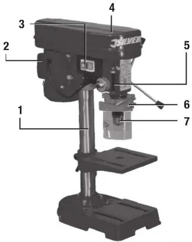
text_image
1 2 3 4 5 6 7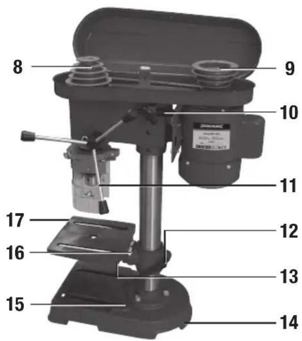
text_image
8 9 10 11 12 13 14 15 16 17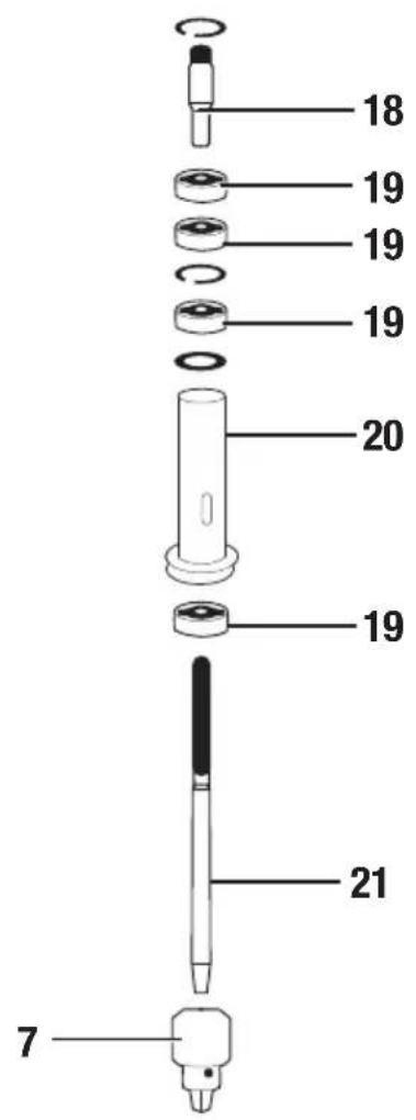
text_image
18 19 19 19 20 19 21 7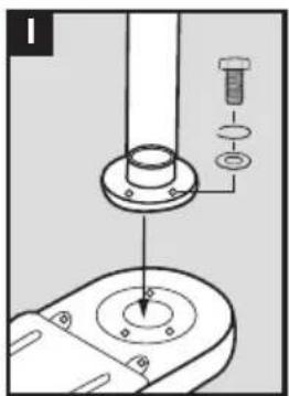
natural_image
Technical diagram showing a mechanical assembly with a flange, bolt, and threaded component (no text or labels)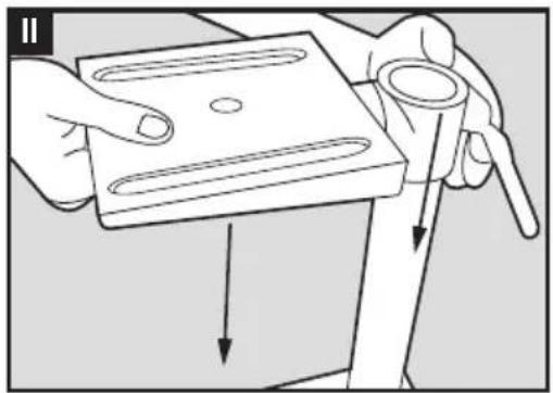
natural_image
Illustration of a hand holding a rectangular object with internal oval patterns, being lifted by a tool (no text or symbols present)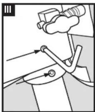
natural_image
Mechanical diagram showing a lever mechanism with arrows indicating motion (no text or symbols)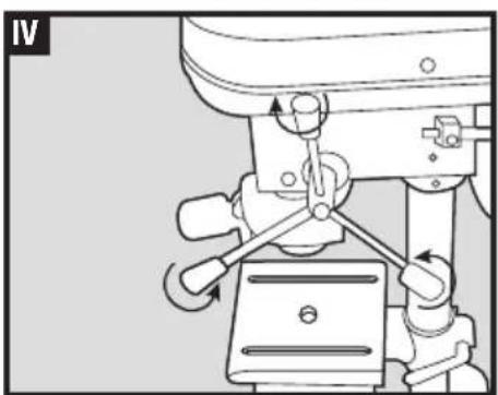
natural_image
Mechanical assembly diagram showing a turning mechanism with no visible text or symbols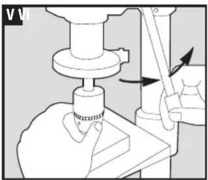
natural_image
Mechanical diagram showing a hand operating a workpiece with a tool, no visible text or symbols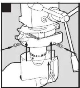
natural_image
Mechanical assembly diagram showing a clamping mechanism with arrows indicating motion (no text or labels)RANGE SILVERLINEC® B-ILL PRESS
350W Drill Press
English 4
Français ...... 10
Deutsch 16
Español 22
Italiano 28
Nederlands......34
Introduction
Thank you for purchasing this Silverline tool. This manual contains information necessary for safe and effective operation of this product. This product has unique features and, even if you are familiar with similar products, it is necessary to read this manual carefully to ensure you fully understand the instructions. Ensure all users of the tool read and fully understand this manual.
Description of Symbols
The rating plate on your tool may show symbols. These represent important information about the product or instructions on its use.

Wear hearing protection Wear eye protection Wear breathing protection Wear head protection

Wear hand protection

Read instruction manual

Caution!

For indoors use only!

Always disconnect from the power supply when adjusting, changing accessories, cleaning, carrying out maintenance and when not in use!

Class I construction (Protective earth)

Conforms to relevant legislation and safety standards

Environmental Protection
Waste electrical products should not be disposed of with household waste. Please recycle where facilities exist. Check with your local authority or retailer for recycling advice
Technical Abbreviations Key
| V Volts | |
| -, AC Alternating current | |
| A, mA Ampere, milli-Amp | |
| n_0 | No load speed |
| n Rated speed | |
| ° Degrees | |
| θ Diameter | |
| Hz Hertz | |
| ---, DC Direct current | |
| W, KW Watt, kilowatt | |
| /min or min^-1 | Operations per minute |
| rpm Revolutions per minute | |
| dB(A) Decibel sound level (A weighted) | |
| m/s^2 | Metres per second squared (vibration magnitude) |
Specification
Voltage 230V, 50Hz
Power 350W
Motor type....Induction
Operating time (max) 30min (S2 duty cycle)
Motor speed: n _c : 1440/min
No load speed 580, 850, 1220, 1650 & 2650/min
Speeds 5
Chuck size....13mm (1.5 - 13mm)
Table size 160x160mm
Table Tilt Angle Scale....+/- 45°
Chuck centre to column (throat) 104mm
Chuck/Spindle Travel 50mm
Chuck to base (max)....295mm
Chuck to table 0-210mm
Protection class....
Ingress protection IP20
Dimensions (L x W x H): 355 x 225 x 440mm
Weight 14.Skg
As part of our ongoing product development, specifications of Silverline products may alter without notice.
Sound and vibration information:
Sound Pressure L_dc : 66dB(A)
Sound power L _max : 79dB(A)
Uncertainty K: 3dB
The sound intensity level for the operator may exceed 85dB(A) and sound protection measures are necessary.
WARNING: Always wear ear protection where the sound level exceeds 85dB(A) and limit the time of exposure if necessary. If sound levels are uncomfortable, even with ear protection, stop using the tool immediately and check the ear protection is correctly fitted and provides the correct level of sound attenuation for the level of sound produced by your tool.
WARNING: User exposure to tool vibration can result in loss of sense of touch, numbness, tingling and reduced ability to grip. Long-term exposure can lead to a chronic condition. If necessary, limit the length of time exposed to vibration and use anti-vibration gloves. Do not operate the tool with hands below a normal comfortable temperature, as vibration will have a greater effect. Use the figures provided in the specification relating to vibration to calculate the duration and frequency of operating the tool.
Sound and vibration levels in the specification are determined according to EN61029 or similar international standards. The figures represent normal use for the tool in normal working conditions. A poorly maintained, incorrectly assembled, or misused tool, may produce increased levels of noise and vibration. www.osha.europa.eu provides information on sound and vibration levels in the workplace that may be useful to domestic users who use tools for long periods of time.
General Power Tool Safety Warnings
WARNING! When using electric power tools, basic safety precautions should always be followed to reduce the risk of fire, electric shock and personal injury including the following safety information. Read all these instructions before attempting to operate this product and save these instructions for future use.
WARNING: This appliance is not intended for use by persons (including children) with reduced, physical or mental capabilities or lack of experience or knowledge unless they have been given supervision or instruction concerning use of the appliance by a person responsible for their safety. Children must be supervised to ensure that they do not play with the appliance.
CAUTION: Use the power tool, accessories and tool bits etc. in accordance with these instructions, taking into account the working conditions and the work to be performed. Use of the power tool for operations different from those intended could result in a hazardous situation.
The term "power tool" in the warnings refers to your mains-operated (corded) power tool or battery-operated (cordless) power tool.
1 - Keep work area clear - Cluttered areas and benches invite injuries
2 - Consider work area environment
- Do not expose tools to rain
- Do not use tools in damp or wet locations
- Keep work area well lit
- Do not use tools in the presence of flammable liquids or gases
3 - Guard against electric shock - Avoid body contact with earthed or grounded surfaces (e.g. pipes, radiators, ranges, refrigerators)
4 - Keep other persons away - Do not let persons, especially children, not involved in the work touch the tool or the extension cord and keep them away from the work area
5 - Store idle tools - When not in use, tools should be stored in a dry locked-up place, out of reach of children
6 - Do not force the tool - It will perform the job better and safer at the rate for which it was intended
7 - Use the right tool - Do not force small tools to do the job of a heavy duty tool. Do not use tools for purposes not intended; for example do not use circular saws to cut tree limbs or logs
8 - Dress appropriately
- Do not wear loose clothing or jewellery, which can be caught in moving parts
- Suitable safety footwear is recommended when working outdoors.
- Wear protective covering to contain long hair
9 - Use protective equipment
- Use safety glasses
- Use face or dust mask if working operations create dust
WARNING: Not using protective equipment or appropriate clothing can cause personal injury or increase the severity of an injury.
10 - Connect dust extraction equipment - If the tool is provided for the connection of dust extraction and collecting equipment, ensure these are connected and properly used
11 - Do not abuse the power cable - Never yank the power cable to disconnect it from the socket. Keep the power cable away from heat, oil and sharp edges. Damaged or entangled power cables increase the risk of electric shock
12 - Secure work - Where possible use clamps or a vice to hold the work. It is safer than using your hand
13 - Do not overreach - Keep proper footing and balance at all times
14 - Maintain tools with care
- Keep cutting tools sharp and clean makes the tool easier to control and less likely to bind or lock in the workpiece
- Follow instruction for lubricating and changing accessories
- Inspect tool power cables periodically and if damaged have them repaired by an authorized service facility
- Inspect extension cables periodically and replace if damaged
- Keep handles dry, clean and free from oil and grease
WARNING: Many accidents are caused by poorly maintained power tools.
15 - Disconnect tools - When not in use, before servicing and when changing accessories such as blades, bits and cutters, disconnect tools from the power supply
WARNING: The use of accessories or attachments not recommended by the manufacturer may result in a risk of injury to persons.
16 - Remove adjusting keys and wrenches - Form the habit of checking to see that keys and adjusting wrenches are removed from the tool before switching it on
17 - Avoid unintentional starting - Ensure switch is in "off" position when connecting to a mains socket or inserting a battery pack, or when picking up or carrying the tool
WARNING: Unintended starting of a tool can cause major injuries.
18 - Use outdoor extension leads - When the tool is used outdoors, use only extension cords intended for outdoor use and so marked. Use of an extension cable suitable for outdoor use reduces the risk of electric shock
19 - Stay alert
- Watch what you are doing, use common sense and do not operate the tool when you are tired
- Do not use a power tool while you are under the influence of drugs, alcohol or medication
WARNING: A moment of inattention while operating power tools may result in serious personal injury.
20 - Check damaged parts
- Before further use of tool, it should be carefully checked to determine that it will operate properly and perform its intended function
- Check for alignment of moving parts, binding of moving parts, breakage of parts, mounting and any other conditions that may affect its operation
- A guard or other part that is damaged should be properly repaired or replaced by an authorized service centre unless otherwise indicated in this instruction manual
- Have defective switches replaced by an authorized service centre
WARNING: Do not use the tool if the on/off switch does not turn it on and off. The switch must be repaired before the tool is used.
21 - Have your tool repaired by a qualified person - This electric tool complies with the relevant safety rules. Repairs should only be carried out by qualified persons, otherwise this may result in considerable danger to the user
WARNING: When servicing use only identical replacement parts.
WARNING: If the power cable is damaged it must be replaced by the manufacturer or an authorised service centre.
22 - Power tool mains plugs must match the mains socket - Never modify the plug in any way. Do not use any adapter plugs with earthed (grounded) power tools. Unmodified plugs and matching sockets will reduce risk of electric shock
23 - If operating a power tool outside use a residual current device (RCD) - Use of an RCD reduces the risk of electric shock
NOTE: The term "residual current device (RCD)" may be replaced by the term "ground fault circuit interrupter (GFCI)" or "earth leakage circuit breaker (ELCB)".
WARNING: When used in Australia or New Zealand, it is recommended that this tool is ALWAYS supplied via Residual Current Device (RCD) with a rated residual current of 30mA or less.
WARNING: Before connecting a tool to a power source (mains switch power point receptacle, outlet, etc.) be sure that the voltage supply is the same as that specified on the nameplate of the tool. A power source with a voltage greater than that specified for the tool can result in serious injury to the user, and damage to the tool. If in doubt, do not plug in the tool. Using a power source with a voltage less than the nameplate rating is harmful to the motor.
Additional Safety for Bench or Stationary Drills
For safety relating to protective clothing/equipment and general health hazards relating to power tools; refer to General and Electrical Safety sections in this manual
- Important: It is imperative to follow all national safety regulations concerning installation, operation and maintenance
- Do not allow anyone under the age of 18 years to use this tool, and ensure that operators are qualified and familiar with the operating and safety instructions
- When using the drill, use safety equipment including safety glasses or shield, ear defenders, and protective clothing. Wear a dust mask if the drilling operation creates dust. Do not wear gloves due to the danger of loose threads dragging a hand in to the drill mechanism
- Extension cable reels used with this tool must be completely unwound. Minimum conductor cross section: 1.0mm2
- Ensure that the lighting is adequate
- Ensure that the drill bit is securely fixed in the chuck. Insecure drill bits can be ejected from the machine causing a hazard
- Ensure that the drill bit is not in contact with the workpiece prior to starting up the tool
- Before drilling, check that there is sufficient clearance for the drill bit under the workpiece
- Do not put pressure on the tool, to do so would shorten its service life
- If required use coolant or cutting fluid to protect the drill bit and workpiece from excessive heat
- Drill bits get hot during operation, allow to cool prior to handling them
- Never use your hands to remove sawdust, chips or waste close by the bit
- If you are interrupted when operating the drill, complete the process and switch off before looking up
- Where possible, use clamps or a vice to hold your work
• Always disconnect the drill from the electric supply before changing a bit - Examine the chuck regularly for signs of wear or damage. Have damaged parts repaired by a qualified service centre
- On completion of the work, disconnect the tool from the power source and remove bit from the machine
• Periodically check all nuts, bolts and other fixings and tighten where necessary
Product Familiarisation
| 1 Column |
| 2 Motor |
| 3 On/Off Switch |
| 4 Pulley Cover |
| 5 Drilling Depth Gauge |
| 6 Chuck Guard |
| 7 Chuck |
| 8 Spindle Pulley |
| 9 Motor Pulley |
| 10 Drive Belt Tension Adjuster |
| 11 Plunge Handles |
| 12 Table Locking Handle |
| 13 Table |
| 14 Base |
| 15 Base Holes |
| 16 Table Tilt Angle Scale |
| 17 Table Tilt Bolt (hidden) |
| 18 Spline Sleeve |
| 19 Bearings |
| 20 Spindle Sleeve |
| 21 Spindle |
Accessories included:
Hex key & chuck key
Intended Use
Bench mounted vertical drill for drilling a wide range of materials excluding most masonry materials. Enables precise control of depth, hole position and angle entry into the workpiece. Provides a stable platform when using accessories compatible with a normal chuck.
Unpacking your Tool
Carefully unpack and inspect your tool. Familiarise yourself with all its features and functions. Ensure that all parts of the tool are present and in good condition. If any parts are missing or damaged, have such parts replaced before attempting to use this tool
Before Use

WARNING: Ensure the tool is disconnected from the power supply before attaching or changing any accessories, or making any adjustments.
Assembling Your Drill Press
Tools required for assembly and operating (not included): Phillips screwdriver & Spanner
Note: This product will have traces of oil and grease on its component parts to protect against corrosion. Clean off such residue before assembly especially the chuck mounting and the internal fitting of the Chuck (7).
-
Secure the Column (1) to the Base (14) using the supplied bolts (x3), spring washers (x3) and washers (x3) included. The spring washers fit between the bolt head and the washer (Fig. I)
-
Slide the Table (13) on to the Column (1) and tighten the Table Locking Handle (12) when approximately 150mm from the base (Fig. II)
-
Place the drill press head assembly on to the Column and lower it as far as it will go Note: Seek assistance when handling the drill press head assembly as it is heavy.
-
When the head is aligned to the base, tighten the 2 hex grub screws which hold the drill press head assembly in place with the supplied Hex key (Fig. III). These hex grub screws are directly below The Drive Belt Tension Adjuster (10) on the same side
-
Screw the three Plunge Handles (11) into the Plunge Handles mounting (Fig. IV)
-
The chuck fits using a simple Morse taper connection and relies on the friction of the surfaces to hold the chuck in position. Fit the chuck to the chuck mounting by placing a small piece of wood below the chuck and operate the Plunge Handles to lower the chuck mounting to fit the Chuck (Fig. V). You can alternatively fit the chuck before mounting the drill press head assembly on the column. If necessary use a soft mallet to help secure the Chuck but only use light force
Note: It is essential both surfaces are free of oil and grease for the chuck to be secure.
Note: Make sure the chuck jaws are recessed before striking the chuck with a mallet.
-
Angle the Chuck Guard (6) so you can remove the screws (x3), washers (x3) and nuts (x3) that are pre-fitted to the chuck guard that will secure the chuck guard visor. Fit the visor (Fig. VI) and then loosely re-assemble the screws, washers and nuts in each hole. Ensure the visor position is correct then tighten the fittings.
-
It is important to secure the drill press to a work surface to prevent the tool tipping over. Fit bolts and nuts (not provided) through the Base Holes (15) and matching holes through a work surface to secure the drill press
Note: Use nylon insert lock nuts or spring washers in the fixings to prevent vibration from loosening the fixings.
Note: If you don't secure the drill permanently it is recommended to use clamps to secure the tool to a work surface or work only with material too small to cause the drill to tip over.
Adjusting speed
IMPORTANT: The drill may need adjustment of the Drive Belt Tension Adjuster (10) before use even if you use the gear already set.
| Belt Position Speed | (min ^-1 ) | Spiral drill bit (metal) | Brad-point drill bit (wood) | Forstner bit (wood) |
| 89 | 580 | 11 - 13mm | >25mm | 35 - 50mm |
| 89 | 850 | 8 - 10mm | 25mm | 28 - 32mm |
| 89 | 1220 | 5 - 7mm | 20mm | 19 - 25mm |
| 89 | 1650 | 3 - 4mm | 3-15mm | 13 - 16mm |
| 89 | 2650 1-2mm | <16mm |
- The drill has 5 speeds which are manually set. See chart below showing belt positions for each speed plus an approximate speed guide for type and size of drill bit.
- Disconnect the drill press from its power supply before attempting to changing the speed
- Remove the single Phillips screw that secures Pulley Cover (4). It is above the Drive Belt Tension Adjuster (10) and open the pulley cover
- The speed is adjusted by the belt that connects the Spindle Pulley (8) and the Motor Pulley (9)
- To move the belt, loosen the Drive Belt Tension Adjuster (10) and pull the Motor (2) towards the front of the drill
- Position the belt onto the desired step on the pulleys according to the table above or the provided table inside the lid of the pulley cover
IMPORTANT: Only operate the drill with the belt level. Operating the drill press with the belt angled will result in serious damage to the tool and will invalidate the guarantee.
- Lever the motor away from the front of the drill to tension the belt, then tighten the drive belt tension adjuster and re-fit the pulley cover securing screw
Note: Low tension will cause the belt to slip and may cause the drill bit to lock in the material. Over tensioning will cause excessive wear and noise. Correct tensioning is tensioning at the first point where the belt can't slip in use and will provide maximum life for the belt. As the belt ages and stretches tension will have to be increased again. Eventually a replacement belt may be required.
Note: The pulley cover has a safety device which prevents the tool working if the pulley cover isn't closed and can be seen inside the cover. If the tool fails to operate make sure the pulley cover is closed correctly.
Operation

WARNING: ALWAYS wear eye protection, adequate respiratory and hearing protection, as well as suitable gloves, when working with this tool.

WARNING: ENSURE gloves and clothes worn do not have loose threads that could get caught by the rotating spindle and drag your hand or head into the rotating spindle causing severe injury. It is recommended to wear gloves that are not fabric based.
Plunge Handles
The Plunge Handles (11) should always be used to feed the drill bit into the material. Pull down on the handle to make the chuck move downwards towards the table. The plunge mechanism will automatically return to a high position removing the drill bit from the workpiece if the Plunge Handles aren't turned. Always control this ascent, do not let go of the Plunge Handles in use.
Operating the chuck
The Chuck (7) can be opened or closed by using the provided chuck key. It is capable of securing drill bits with shanks from 1.5 - 13mm.
Note: Ensure that the chuck is fully tightened before attempting to drill as it could cause severe and permanent damage to the chuck and may invalidate the guarantee.
WARNING: Never fit any attachment with a maximum speed lower than the no load speed of the belt position speed that the drill has been set to.
On/Off switch
To start the drill, press the 'I' Button of the On/Off Switch (3)
To stop the drill, press the 'O' Button
WARNING: Do not operate this tool for longer than 15 minutes in one continuous operation and allow the tool to cool between long operations.
Table
The table can be adjusted for height, rotation and tilt. It has 2 slots for securing a vice (not supplied) to the table surface and a central hole for allowing a drill bit to pass through the material being drilled without damaging the surface of the table.
Position Adjustment
- Loosen the Table Locking Handle (12)
- Move the table to the height and rotation position for the required hole in the material being drilled
- Tighten the handle once table position has been confirmed
- To adjust tilt, loosen Table Tilt Bolt (17) with a spanner (not supplied) and adjust using the Table Tilt Angle Scale (16) to give the approximate required angle or set the table exactly level using a spirit level. Then re-tighten the bolt
Note: Ensure that the table is securely tightened in position prior to use.
Drilling Depth
You can adjust the drilling depth by limiting the movement of the chuck/spindle. Adjust the 2 nuts on the thread parallel to the Drilling Depth Gauge (5). Set between 0 and 50mm as shown on the gauge. Locking the 2 nuts together at maximum height will give the full 50mm of travel.

CAUTION! Applying excess pressure does not result in faster or more efficient drilling. If the pressure applied to the drill has a noticeable effect on the speed of the drill then reduce the pressure. Overloading the drill will reduce its service life
As the drill bit penetrates the material being drilled, it may 'catch' or 'snag'. This may cause the machine to suddenly 'kick'. To prevent any possibility of injury always ensure the material is held securely by a vice or a clamp, and use sharp drill bits.
Drilling wood
- Ensure that drill bits are suitable for wood and have a maximum rpm above the set speed of the drill

WARNING: DO NOT inhale wood dust. Wear adequate breathing protection. Some wood dusts may be toxic.
Drilling metal
- Ensure that drill bits are suitable for the grade of metal being drilled and have a maximum rpm above the set speed of the drill

WARNING: The drill bit and the workpiece will become very hot when drilling metal. DO NOT touch the bit and never allow it to come into contact with combustible materials when hot. Always use a suitable lubricant or cutting fluid, and drill at appropriate speeds.
- Only apply moderate pressure to the drill bit, ensuring efficient cutting and prolonged drill bit life
- Use a countersink bit to remove sharp burrs from the hole, preventing cuts and other kinds of injury.
Accessories
- A full range of accessories including drill bits, holesaws, wire brushes etc. is available from your Silverline dealer
• Drill Press Vice 65mm (380677)
• Drill Press Vice 100mm (292674)
• Quick Release Drill Vice 100mm (380956)
Maintenance

WARNING: Always disconnect from the power supply before carrying out any maintenance/cleaning.
General inspection
- Regularly check that all the fixing screws are tight. They may vibrate loose over time
- Inspect the supply cord of the tool, prior to each use, for damage or wear. Repairs should be carried out by an authorised Silverline service centre. This advice also applies to extension cords used with this tool
Lubrication
- This drill press comes correctly lubricated with grease and oil for the spindle mechanism parts which will be sufficient for years of normal occasional use. However if the drill press is frequently used it may need to be re-lubricated on a yearly basis. Instructions on dismantling and re-assembling the spindle section are beyond the scope of this manual. However, general advice for lubrication is as follows:
- After dismantling, clean the components removing the old lubrication and check for component excessive wear or damage
- Lubricate the Bearings (19) with a good quality lithium-based grease. For sealed bearings check functionality and grease them externally. Fill the Spline Sleeve (18) and Spindle Sleeve (20) with grease and ensure the Spindle (21) is also greased
- A light coating of engine oil can be applied for parts where grease cannot be applied or where there is surface friction
Cleaning
WARNING: ALWAYS wear protective equipment including eye protection and gloves when cleaning this tool.
- Keep your tool clean at all times. Dirt and dust will cause internal parts to wear quickly, and shorten the device's service life
- Clean the body of your machine with a soft brush, or dry cloth
- Never use caustic agents to clean plastic parts. If dry cleaning is not sufficient, a mild detergent on a damp cloth is recommended
• Water must never come into contact with the tool - Ensure the tool is thoroughly dry before using it
- If available, use clean, dry, compressed air to blow through the ventilation holes (where applicable)
Storage
- Store this tool carefully in a secure, dry place out of the reach of children. If the tool is permanently set up in a workshop or garage, ensure access is restricted to prevent children operating the tool.
Disposal
Always adhere to national regulations when disposing of power tools that are no longer functional and are not viable for repair.
- Do not dispose of power tools, or other waste electrical and electronic equipment (WEEE), with household waste
- Contact your local waste disposal authority for information on the correct way to dispose of power tools
Troubleshooting
| Problem Possible Cause Solution | ||
| Drill press will not start | Mains connection not correct Check mains plug is fully inserted in | socket and socket is switched on. If RCD is fitted check that it is reset/on |
| Mains plug fuse blown Check fuse in mains plug and replace if necessary with same value | ||
| Pulley Cover (4) not closed Ensure Pulley Cover is fully closed and securely fastened. If necessary also check the safety switch mechanism inside the Pulley Cover is not damaged. | ||
| On/Off Switch (3) faulty or another tool fault Contact your Silverline dealer or authorised service centre | ||
| Abnormal or high levels of operating noise | Incorrect belt tension Adjust tension (see Adjusting Speed) | |
| Spindle needs lubricating See ‘Maintenance’. Contact your Silverline dealer or an authorised service centre if necessary | ||
| Worn or damaged pulley drive belt Replace belt. Contact your Silverline dealer or www.toolsparesonline.com for a replacement belt. | ||
| Loose screws or other fittings Check body of tool and inside Pulley Cover to make sure all parts are secure and correctly fitted | ||
| Drill bit smoking and excessive heat | Speed setting incorrect Change speed (see Adjusting Speed) | |
| Blunt drill bit Replace or sharpen drill bit | ||
| Material or drill bit should not be drilled dry Use lubricant or cutting fluid | ||
| Drill bit wobble or run out | Bent drill bit Replace drill bit | |
| Drill bit not centrally located in Chuck Re-fit drill bit in chuck | ||
| Worn spindle bearings or other parts | Contact your Silverline dealer or an authorised service centre | |
| Drill bit binds in workpiece | Pulley belt has incorrect low tension | Adjust tension (see Adjusting Speed) |
Silverline Tools Guarantee
This Silverline product comes with a 3 year guarantee
Register this product at www.silverlinetools.com within 30 days of purchase in order to qualify for the 3 year guarantee. Guarantee period begins according to the date of purchase on your sales receipt.
Registering your purchase
Registration is made at silverlinetools.com by selecting the Guarantee Registration button. You will need to enter:-
- Your personal details
• Details of the product and purchase information
Once this information is entered your guarantee certificate will be created in PDF format for you to print out and keep with your purchase.
Terms & Conditions
Guarantee period becomes effective from the date of retail purchase as detailed on your sales receipt.
PLEASE KEEP YOUR SALES RECEIPT
If this product develops a fault within 30 days of purchase, return it to the stockist where it was purchased, with your receipt, stating details of the fault. You will receive a replacement or refund.
If this product develops a fault after the 30 day period, return it to:
Silverline Tools Service Centre
PO Box 2988
Yeovil
BA21 1WU, UK
The guarantee claim must be submitted during the guarantee period.
You must provide the original sales receipt indicating the purchase date, your name, address and place of purchase before any work can be carried out. You must provide precise details of the fault requiring correction. Claims made within the guarantee period will be verified by Silverline Tools to establish if the deficiencies are related to material or manufacturing of the product.
Carriage will not be refunded. Items for return must be in a suitably clean and safe state for repair, and should be packaged carefully to prevent damage or injury during transportation. We may reject unsuitable or unsafe deliveries.
All work will be carried out by Silverline Tools or its authorized repair agents. The repair or replacement of the product will not extend the period of guarantee.
Defects recognised by us as being covered by the guarantee shall be corrected by means of repair of the tool, free of charge (excluding carriage charges) or by replacement with a tool in perfect working order.
Retained tools, or parts, for which a replacement has been issued, will become the property of Silverline Tools.
The repair or replacement of your product under guarantee provides benefits which are additional to and do not affect your statutory rights as a consumer.
What is covered:
The repair of the product, if it can be verified to the satisfaction of Silverline Tools that the deficiencies were due to faulty materials or workmanship within the guarantee period.
If any part is no longer available or out of manufacture, Silverline Tools will replace it with a functional replacement part.
Use of this product in the EU.
What is not covered:
Silverline Tools does not guarantee repairs required as a result of:
Normal wear and tear caused by use in accordance with the operating instructions eg blades, brushes, belts, bulbs, batteries etc.
The replacement of any provided accessories drill bits, blades, sanding sheets, cutting discs and other related items.
Accidental damage, faults caused by negligent use or care, misuse, neglect, careless operation or handling of the product.
Use of the product for anything other than normal domestic purposes.
Change or modification of the product in any way.
Use of parts and accessories which are not genuine Silverline Tools components.
Faulty installation (except installed by Silverline Tools).
Repairs or alterations carried out by parties other than Silverline Tools or its authorized repair agents.
Claims other than the right to correction of faults on the tool named in these guarantee conditions are not covered by the guarantee.
Battery Guarantee
Silverline batteries are guaranteed for 30 days. If a defect occurs on a registered battery during the term of the Battery Guarantee, due to material or manufacturing fault, then Silverline will replace it free of charge. This guarantee does not apply to commercial use nor does it extend to normal wear and tear or damage as a result of accident, abuse or misuse.
CE Declaration of Conformity
The undersigned: Mr Darrell Morris
as authorised by: Silverline
Declares that:
This declaration has been issued under the sole responsibility of the manufacturer.
The object of the declaration is in conformity with the relevant Union harmonisation Legislation.
Identification code: 262212
Description: Bench Drill Press
Conforms to the following directives and standards:
• Machinery Directive 2006/42/EC
• Low Voltage Directive 2014/35//EU
• EMC Directive 2014/30/EU
• RoHS Directive 2011/65/EU
• EN 61029-1:2009+A11:2010
• EN ISO 12100:2010
• EN 55014-1:2006+A2:2011
• EN 55014-2:1997+A2:2008
• EN 61000-3-2:2014
• EN 61000-3-3:2013
• EN 62321:2009
Notified body: TÜV SÜD Product Service
The technical documentation is kept by: Silverline
Date: 25/05/2016
Signed:

Mr Darrell Morris
Managing Director
Name and address of the manufacturer:
Powerbox International Limited, Company No. 06897059.
Registered address: Powerbox Int. Ltd. Somerset, BA22 8HZ, United Kingdom.
Introduction
Silverline Tools Service Centre
PO Box 2988
Yeovil
Technical Abbreviations Key
Bohrfutter....13 mm (1,5–13 mm)
Silverline Tools Service Centre
PO Box 2988
Yeovil
Silverline Tools Service Centre
PO Box 2988
Yeovil
BA21 1WU, GB
Signor Darrell Morris
Silverline Tools Service Centre
PO Box 2988
Yeovil
BA21 1WU, GB
natural_image
Industrial drill press machine with base mount and control panel (no visible text or symbols)
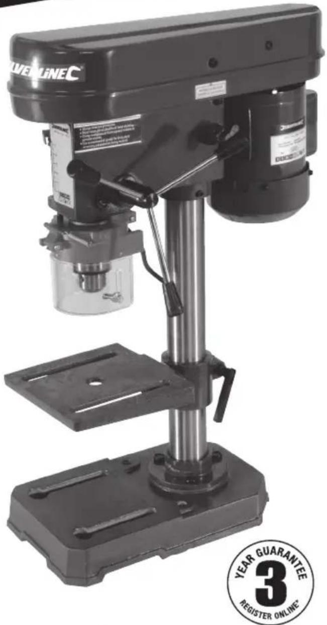
3 Year Guarantee
*Register online within 30 days. Terms & Conditions apply