
Pro Elyo Touch - Swimming Pool ASTRALPOOL - Free user manual and instructions
Find the device manual for free Pro Elyo Touch ASTRALPOOL in PDF.
| Product type | Pool heat pump |
| Brand | AstralPool |
| Model | Pro Elyo Touch (PET-08 to PET-35T) |
| Product codes | 74166 to 74175 |
| Dimensions (L x W x H) | Approximately 1000 x 400 x 800 mm to 1400 x 600 x 1000 mm depending on model |
| Net / gross weight | 60-158 kg depending on model |
| Power supply | 220-240 V ~ 50 Hz (single phase) or 380-400 V 3N~ 50 Hz (three phase) depending on model |
| Rated current | 4.6 A to 22.9 A (single phase) / 7 A to 8.4 A (three phase) |
| Heating capacity | 8.5 kW to 35 kW depending on model and conditions |
| COP | Up to 16 under optimal conditions |
| Refrigerant | R32 (GWP=675) for most models; R410A (GWP=2088) for PET-30T and PET-35T |
| Refrigerant charge | 0.65 kg to 4 kg depending on model |
| Protection rating | IPX4 |
| Sound level at 1 m | 38-60 dB(A) depending on model and mode |
| Main functions | Heating, cooling, Turbo, Smart, Silent modes, timer programming, heating priority, filtration control |
| Connectivity | Modbus / Fluidra Connect (optional) |
| Maintenance and cleaning | Regular cleaning of the evaporator, winter drain, annual maintenance by qualified technician |
| Safety | IPX4 protection, 30mA RCD, high/low pressure protection, anti-freeze, multiple error codes |
| Spare parts and repairability | Detailed list of spare parts in the manual; exploded diagrams provided |
| Warranty | 2 years (specific conditions in the manual) |
Frequently Asked Questions - Pro Elyo Touch ASTRALPOOL
User questions about Pro Elyo Touch ASTRALPOOL
0 question about this device. Answer the ones you know or ask your own.
Ask a new question about this device
Download the instructions for your Swimming Pool in PDF format for free! Find your manual Pro Elyo Touch - ASTRALPOOL and take your electronic device back in hand. On this page are published all the documents necessary for the use of your device. Pro Elyo Touch by ASTRALPOOL.
USER MANUAL Pro Elyo Touch ASTRALPOOL
natural_image
Technical line drawing of a fan assembly with internal blades and a small container (no text or symbols)ENGLISH----P69
FRENCH----P122
NEDERLANDS----P176
SPANISH----P227
GERMAN----P279
ITALIAN P332
PORTUGUESE----P385
GREEK----P437
Swedish----P492
 | This symbol shows that information is available such as the Operating Manual of Installation Manual. |  | This symbol shows that this appliance uses R32, a low burning velocity refrigerant (not applicable for references 74174 and 74175) |
 | This symbol shows that the Operation Manual should be read carefully. |  | This symbol shows that service personnel should be handling this equipment with reference to the Installation Manual. |
GENERAL WARNINGS
- Failure to respect the warnings may cause serious damage to the pool equipment or cause serious injury, even death.
- Only a person qualified in the technical fields concerned (electricity, hydraulics or refrigeration) is authorised to carry out maintenance or repair work on the appliance. The qualified technician working on the appliance must use/wear personal protective equipment (such as safety goggles and protective gloves, etc.) in order to reduce the risk of injury occurring when working on the appliance.
- Before handling the appliance, check that it is switched off and isolated.
- This appliance is not intended for use by individuals (including children, over the age of 8) lacking in experience or with impaired physical, sensory or mental capabilities, unless: they receive supervision and are instructed on how to use the appliance by a person responsible for their safety; and if they understand the hazards involved.
- Children must be supervised to ensure that they do not play with the appliance.
- The appliance must be installed according to the manufacturer's instructions and in compliance with local and national standards. The installer is responsible for installing the appliance and for compliance with national installation regulations. Under no circumstances may the manufacturer be held liable in the event of failure to comply with applicable local installation standards.
- For any work other than the simple user maintenance described in this manual, the product should be referred to a qualified professional.
- Incorrect installation and/or use may cause serious damage to property or serious injuries (possibly causing death).
- If the appliance suffers a malfunction, do not try to repair it yourself; instead contact a qualified technician.
- Deactivating, eliminating or by-passing any of the safety mechanisms integrated into the appliance shall automatically void the warranty, in addition to the use of spare parts manufactured by unauthorised third-party manufacturers.
- Do not spray insecticide or any other chemical (flammable or non-flammable) in the direction of the appliance, as this may damage the body and cause a fire.
- Do not touch the fan or moving parts and do not place objects or your fingers in the vicinity of the mov
parts when the appliance is in operation. Moving parts can cause serious injury or even death.
WARNINGS ASSOCIATED WITH ELECTRICAL APPLIANCES
- The power supply to the appliance must be protected by a dedicated 30 mA Residual Current Device (RCD complying with the standards and regulations in force in the country in which it is installed.
- Do not use any extension lead when connecting the appliance; connect the appliance directly to a suitable power supply.
- Before carrying out any operations, check that:
-The voltage indicated on the appliance information plate corresponds to the mains voltage.
-The power grid must be adapted to the power requirements of the appliance, and is grounded.
- Do not disconnect and reconnect the appliance to the power supply when in operation.
- Do not pull on the power cord to disconnect it from the power supply.
- If the power cord is damaged, it must be replaced by the manufacturer, its technician or a qualified person to guarantee safety.
- Do not perform maintenance or servicing operations on the appliance with wet hands or if the appliance is wet.
- Before connecting the appliance to the power supply, check that the connection unit or socket to which the appliance will be connected is in good condition and shows no signs of damage or rust.
- In stormy weather, disconnect the appliance from the power supply to prevent it from suffering lightning damage.
Do not immerse the appliance in water or mud.
WARNINGS CONCERNING APPLIANCES CONTAINING REFRIGERANT R32
- R32 refrigerant is classed under category A2L as mildly flammable.
- Do not release R32 fluid into the atmosphere. These are fluorinated greenhouse gases, covered by the Kyoto Protocol, with a Global Warming Potential (GWP) of 675 (European regulation EU 517/2014).
- The appliance must be stored in a well-ventilated location away from all ignition sources.
- Install the unit outdoors. Do not install the unit indoors or in an enclosed and non-ventilated outdoor location.
- Do not use means for accelerating the defrosting or cleaning process other than those recommended by the manufacturer.
- The appliance must be stored in a room without any permanent ignition source (such as open flames, operating gas appliance or operating electric heating).
- Do not perforate or incinerate.
- Please note that R32 refrigerant may give off a certain odour.
- In order to comply with the applicable standards and regulations in terms of the environment and installation, in particular French decree No. 2015-1790 and/or European regulation EU 517/2014, a leak test must be performed on the cooling circuit at least once a year. This operation must be carried out a specialist certified to test cooling appliances.
- Please keep the display controller in a dry area, or well close the insulation cover to protect the display controller from being damaged by humidity.
INSTALLATION AND MAINTENANCE
- The appliance may not be installed close to combustible materials, or the air duct inlet of an adjacent building.
- With some appliances, it is essential to fit a "protection grid"-type accessory if the unit is installed in an area with uncontrolled access.
- During installation, troubleshooting and maintenance, pipes may not be used as steps: the pipe could
break under the weight, spilling refrigerant and possibly causing serious burns.
- When servicing the appliance, the composition and state of the heat transfer fluid must be checked, as well as the absence of any traces of refrigerant.
- During the annual appliance sealing test in accordance with applicable legislation, the high and low pressure switches must be checked to ensure that they are securely fastened to the refrigerant circuit and that they cut off the electrical circuit when tripped.
- During maintenance work, ensure there are no traces of corrosion or oil around the cooling components.
- Before beginning work on the cooling circuit, stop the appliance and wait for a few minutes before fitting the temperature and pressure sensors. Some elements such as the compressor and piping may reach temperatures in excess of 100^ and high pressures with the consequent risk of severe burns.
- Do not braze or weld the pipe if there is refrigerant inside machine. Please do not charge the gas when in a confined space.
MAINTENANCE : WARNINGS CONCERNING APPLIANCES CONTAINING R32 REFRIGERANT
Area check
- Before starting work on systems containing flammable refrigerants, safety checks must be carried out to guarantee a minimal ignition risk.
Work procedure
- The work must be carried out according to a controlled procedure in order to reduce the risks of releasing a flammable gas or vapour while working.
General work area
- All maintenance staff and other personnel working in the surrounding area must be made aware of the work carried out. Work conducted in enclosed areas must be avoided.
Check for the presence of refrigerant
- The area must be analysed using a suitable refrigerant detector before and during work so that the technician is informed of the presence of a potentially toxic or flammable atmosphere. Check that the leak detection equipment used is suitable for use with all refrigerants concerned, i.e. that it does not cause a spark, is correctly isolated or is entirely safe.
Check for the presence of a fire extinguisher
- If work must be carried out on the cooling equipment or any part associated therewith at a certain temperature, suitable fire extinguishing means must be within reach. Place a dry chemical fire extinguisher or COfire extinguisher near the work area.
No source of ignition
- No person carrying out work on a cooling system involving exposing the piping may use any ignition source, which could create a fire or explosion risk. All possible ignition sources, in particular cigarettes, must not enter within a sufficient perimeter of the installation, repair, removal or disposal site, in the event that refrigerant could be released into the surrounding space. Before starting the work, the area around the equipment must be examined to check for all fire or ignition risks. "No smoking" signs must be displayed.
Area ventilation
- Before accessing the unit in any manner whatsoever with the intention of performing any maintenance task, check that the area is open and well-ventilated. Suitable ventilation must be provided throughout the maintenance task to allow any refrigerant that could be released into the atmosphere to be safely dispersed.
Refrigeration equipment check
The manufacturer's recommendations in terms of care and maintenance must always be complied with. When replacing electric components, check that components used are of the same type and category as those recommended/approved by the manufacturer. When in doubt, contact the manufacturer's technical department for assistance.
The following checks must be applied to installations using flammable refrigerants:
-the markings on the equipment must remain visible and legible; any illegible markings or signs must be rectified;
-the hoses or components of the cooling circuit are installed in a position where they are unlikely to be exposed to any substance capable of corroding the components containing refrigerant, unless the components are made from materials that are typically corrosion-proof or correctly protected from such corrosion.
Electric component check
The repair and maintenance of electric components must include initial safety checks and component inspection procedures. If a defect capable of jeopardising safety arises, no power supply must be connected to the circuit until the problem has been completely resolved. If the defect cannot be rectified immediately and if maintenance work must continue, an appropriate temporary solution must be found. This must be reported to the equipment's owner so that all persons concerned are made aware.
The repair and maintenance of electric components must include the following initial safety checks:
-the capacitors are discharged: this must be carried out safely to prevent all risks of ignition;
-no electric component or live wiring is exposed while charging, overhauling or draining the system;
-the system must be grounded at all times.
Repair of insulated components
When repairing insulated components, all power sources must be disconnected from the equipment on which the work is being carried out before removing the insulating cover, etc. If the equipment must be powered during maintenance work, a leak detector must continuously monitor for leaks at the most critical point in order to report any potentially hazardous situation.
Particular attention must be paid to the following points to ensure that, when performing work on the electric components, the housing is not altered to the point of affecting the protection rating. This includes damaged wires, an excessive number of connections, terminals that do not comply with the original specifications, damaged seals, incorrect installation of the cable glands, etc.
Make sure that the appliance is properly fixed.
Make sure that the seals or insulating materials are not deteriorated to the point that they no longer prevent a flammable atmosphere from penetrating the circuit. Spare parts must be compliant with the manufacturer's specifications.
Repair of intrinsically safe components
Do not apply any permanent electric capacitance or induction charge to the circuit without checking that it does not exceed the allowed voltage and intensity for the equipment being used.
Typically safe components are the only types on which work can be carried out in the presence of a flammable atmosphere when live. The test appliance must fall under a suitable classification.
Only replace components with parts specified by the manufacturer. Other parts could cause the refrigerant to leak and ignite in the atmosphere.
Wiring
- Check that the wiring shows no signs of wear, corrosion, excessive pressure, vibration, cutting edges or any other detrimental environmental effect. The check must also take into account the effects of ageing or continuous vibrations caused by sources such as compressors or fans.
Detection of flammable refrigerant
- Under no circumstances must potential ignition sources be used to search for or detect refrigerant leaks. A halide torch (or any other detector using a naked flame) must not be used.
- The following leak detection methods are considered to be acceptable for all cooling systems.
- Electronic leak detectors can be used to detect refrigerant leaks; however, in the case of flammable refrigerants, the sensitivity level may not be suitable or recalibration may be necessary. (The detection equipment must be calibrated in an area devoid of refrigerant). Check that the detector is not a potential ignition source and is appropriate for the refrigerant used. The leak detection equipment must be adjusted to a percentage of the refrigerant's LFL and must be calibrated according to the refrigerant used. The appropriate gas percentage (25% at most) must be confirmed.
- Leak detection fluids are also suited for use with most refrigerants, however the use of detergents containing chlorine must be avoided since it could react with the refrigerant and cause corrosion to the copper piping.
- If a leak is suspected, all naked flames must be removed/extinguished.
- If a refrigerant leak is detected and requires soldering, the entire quantity of refrigerant must be removed from the system or isolated (by way of shut-off valves) in part of the system located away from the leaf
Removal and discharge
- When accessing the cooling circuit to carry out repairs, or for any other reason, conventional procedures must be employed. However, for flammable refrigerants, the recommendations must be complied with in order to take account of the product's flammability. The following procedure must be followed:
- remove the refrigerant;
• purge the circuit with an inert gas (optional for A2L); - drain (optional for A2L);
• purge with an inert gas (optional for A2L); - open the circuit by cutting or soldering.
- The refrigerant charge must be recovered in suitable recovery cylinders. For appliances containing flammable refrigerants other than A2L refrigerants, the system must be bled with nitrogen devoid of oxygen to make the appliance suitable for receiving flammable refrigerants. You may need to repeat this process several times. Compressed air or oxygen must not be used to purge cooling systems.
Loading procedures
- Check that the vacuum pump outlet is not located in the vicinity of any potential ignition source and that ventilation is provided.
- In addition to conventional charging procedures, the following requirements apply.
- Check that there is no possibility of cross-contamination between the different refrigerants when using charging equipment. Hoses or lines must be as short as possible to reduce the quantity of refrigerant contained therein.
- Cylinders must be kept in an appropriate position, in accordance with the instructions.
- Check that the cooling system is grounded before charging the system with refrigerant.
- Label the system once charging is complete (if this is not already the case).
- Pay close attention to not overfilling the cooling system.
- Before recharging the system, carry out a pressure test using a suitable purge gas. The system must be examined to make sure there are no leaks after the charging operation and before commissioning. A
follow-up leak test must be carried out before leaving the site.
Dismantling
- Before dismantling, the technician must familiarise himself/herself with the equipment and its specifications. We highly recommend carefully recovering all refrigerants. Before this, oil and refrigerant samples must be taken if analyses are to be carried out before any other use of the recovered refrigerant. Check for the presence of a power supply before starting work.
- Familiarise yourself with the equipment and how it operates.
- Electrically isolate the system.
- Before starting work, check the following points:
-mechanical handling equipment is available if needed to handle the refrigerant cylinders;
-all personal protective equipment is available and used correctly;
-the recovery process is followed at all times by a cognizant person;
-the recovery cylinders and equipment comply with the relevant standards.
- Drain the cooling system where possible.
- If a vacuum cannot be created, install a manifold in order to be able to remove the refrigerant from various locations within the system.
- Make sure that the cylinder is located on the scales before starting recovery operations.
- Start the recovery unit and operate as per its instructions.
- Do not overfill the cylinders (no more than 80% of the volume must be filled with liquid).
- Do not exceed the maximum working pressure of the cylinder, even temporarily.
- When the cylinders have been filled correctly and the process is complete, check that the cylinders and the equipment are quickly removed from the site and that the alternative shut-off valves on the equipment are closed.
- The recovered refrigerant must not be charged in another cooling system, unless it has been cleaned and inspected.
TROUBLESHOOTING
- All brazing must be carried out by qualified brazers.
- Replacement pipes must always be made of copper in compliance with standard NF EN 12735-1.
- Leak detection; pressure test:
-never use oxygen or dry air, risk of fire or explosion,
-use dry nitrogen or the mixture of nitrogen and refrigerant indicated on the information plate,
-the test pressure for both the high and low pressure circuits must not exceed 42 bar in cases where the appliance is equipped with the optional pressure gauge.
- The high pressure circuit pipes are made of copper and have a diameter equal to or greater than 1"5/8. / certificate as indicated in§2.1 in compliance with standard NF EN 10204 must be requested from the supplier and filed in the installation's technical file.
- Technical data relative to the safety requirements of the various applicable directives are indicated on the information plate. All this information must be recorded in the appliance's installation manual, which must be kept in its technical file: model, code, serial number, maximum and minimum OT, OP, year of manufacture, CE marking, manufacturer's address, refrigerant and weight, electrical parameters, thermo-dynamic and acoustic performance.
LABELLING
- The equipment must be labelled so as to specify that it is out of order and that the refrigerant has been drained.
•The label must be dated and signed. - For appliances containing a flammable refrigerant, check that labels are placed on the equipment stating
that it contains a flammable refrigerant.
RECOVERY
- When draining the refrigerant for maintenance or decommissioning, best practices should be followed in order to safely drain all of the refrigerant.
- When transferring refrigerant to a cylinder, make sure that you use a recovery cylinder that is compatible with the refrigerant. Make sure that the correct number of cylinders are provided for recovering all of the refrigerant. All cylinders used must be intended for the recovery of refrigerant and must be labelled for this specific refrigerant. The cylinders must be equipped with a vacuum valve and a stop gate in good working order. Empty collection cylinders are drained and, where possible, cooled before recovery.
- The recovery equipment must be in good working order, the instructions for using the equipment must be within reach and the equipment must be compatible for use with the refrigerant concerned, including, where appropriate, a flammable refrigerant. Moreover, a set of calibrated scales must be available and in good working order. The pipework must be complete, have no leaks or disconnected connectors, and must be in good condition. Before using the recovery unit, check that it is in good working order, that has been well maintained and that the associated electric components are sealed so as to prevent any risk of fire in the event of refrigerant being released. If you have any doubts, contact the manufacturer.
- The recovered refrigerant must be sent to the refrigerant supplier in its recovery cylinder with a waste transfer note. Do not mix different refrigerants in the recovery units, and in particular in the cylinders.
- If the compressor has been removed or if oil from the compressor has been drained, check that the refrigerant has been completely removed to prevent it from mixing with the lubricant. The draining process must be carried out before returning the compressor to the supplier. Only the electric heater of the compressor body can be used to accelerate this process. This operation can be carried out safely once all liquids within the system have been drained.
RECYCLING
This symbol is required by the European directive 2012/19/EU (directive on waste electrical and electronic equipment) and means that your appliance must not be thrown into a normal bin. It will be selectively collected for the purpose of reuse recycling or transformation. If it contains any substances that may be harmful to environment, these will be eliminated or neutralised. Contact your retailer for recycling information.
ALGEMENE WAARSCHUWINGEN
WAARSCHUWINGEN MET BETREKKING TOT ELEKTRISCHE APPARATEN
User and Service manual
SWIMMING POOL HEAT PUMP
PRO ELYO TOUCH
INDEX
- Description
- Transport information
- Specifications
- Accessories and options
- Location and connection
- Electrical Wiring
- Start-up of the Heat Pump
- Troubleshooting
- Exploded Diagram
- Maintenance
Thank you for using PRO ELYO TOUCH swimming pool heat pump for your pool heating, it will heat your pool water and keep the constant temperature when the air ambient temperature is at -20 to 50°C.

ATTENTION: This manual includes all the necessary information for the use and the installation
your heat pump.
● The installer must read the manual and follow the instructions of implementation and maintenance.
● Failure to respect the warnings may cause serious damage to the pool equipment or cause serious injury, even death.
- The installer is responsible for the installation of the product and should follow all the instructions of the manufacturer and the regulations in application. Incorrect installation will invalidate the guarar
- The manufacturer declines any responsibility for the damage caused by any third party, object ingression and of the errors due to the installation that do not follow the manual guidelines. Any that is not as intended by the manufacturer will invalidate the guarantee.
- Keep and pass on these documents for later viewing throughout the appliance's service life.
1. Description
1.1 Included with your Heat Pump
- Water connection assembly 50 mm (pcs: 2)
- User and service manual
- Reducer connection
- Winter cover
- Anti-vibration base (pcs: 4)
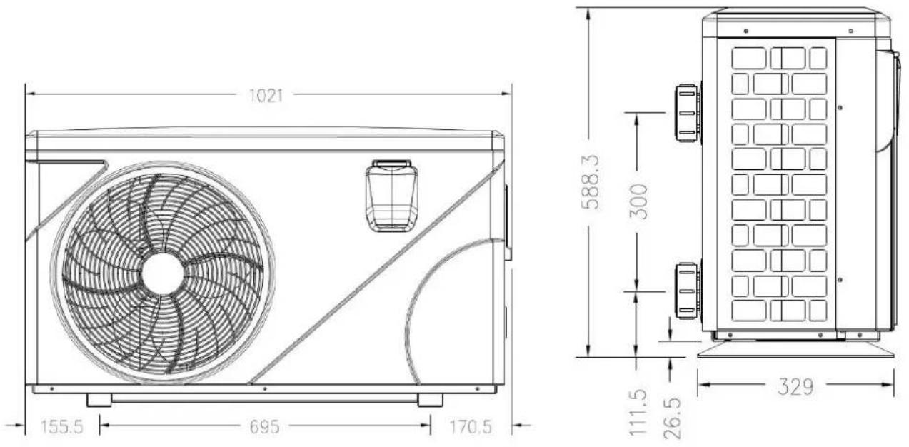
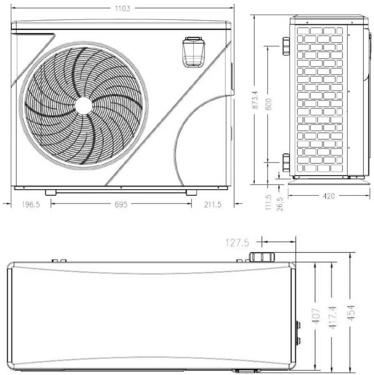
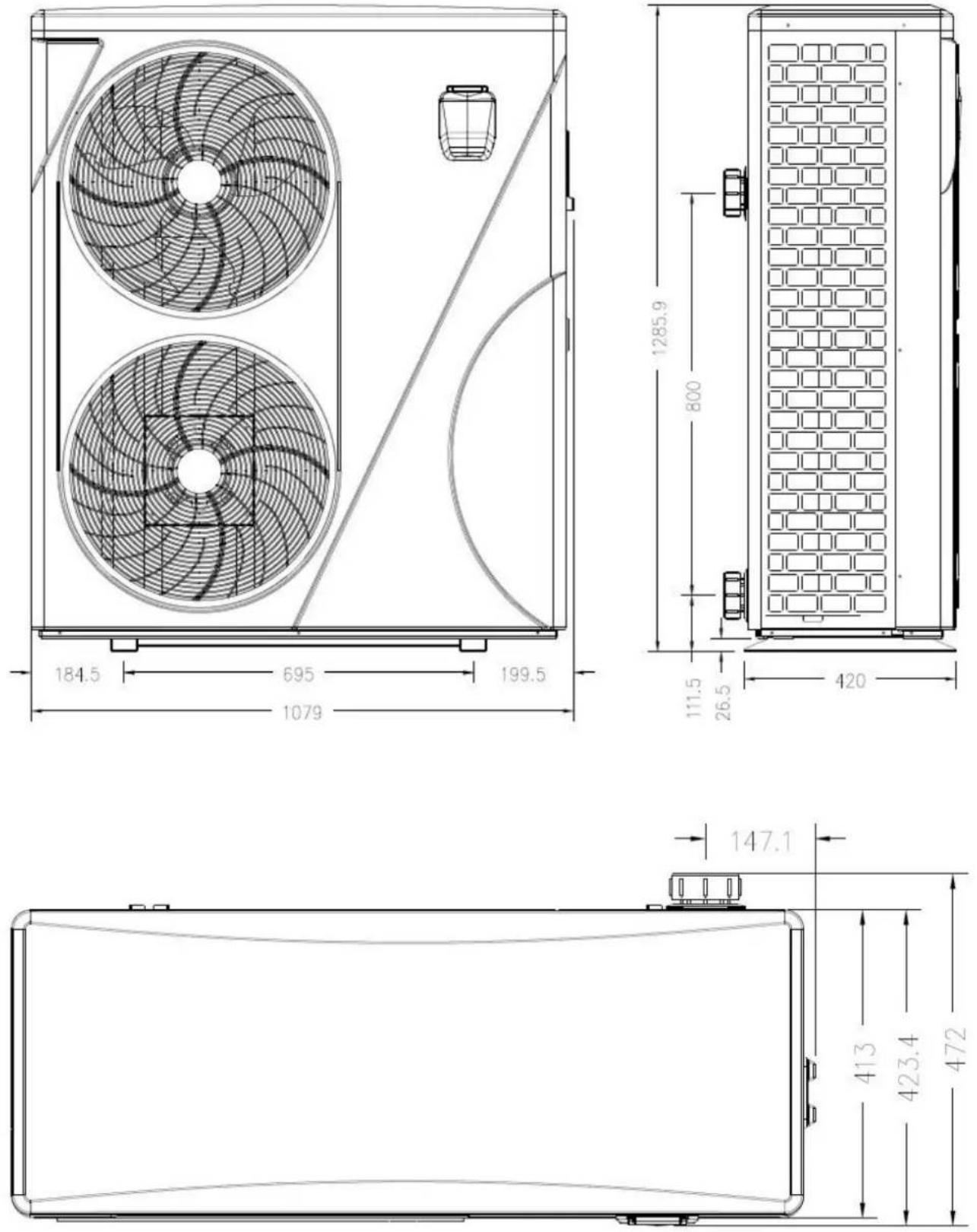
1.2 Dimension
Model: 74166
1. Description
Models: 74167/74168/74169
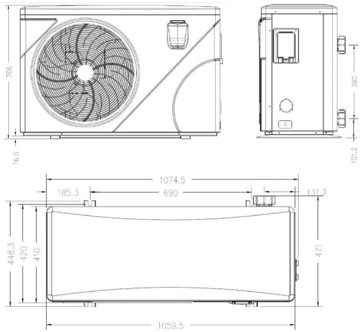
1. Description
Models: 74170/74171
1. Description
Models: 74172/74173/74174/74175
2. Transport information
2.1 Delivery of the unit

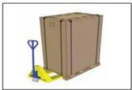
natural_image
Illustration of a brown cardboard box with a blue pallet jack beside it, no text or symbols present.For the transportation, the heat pumps are fixed on the pallet and covered with a cardboard box.
To protect from any damage, the heat pump must be transferred in its package.
It is the responsibility of the addressee to notify of any damage incurred during delivery within 48 hours.
No responsibility can be taken once the unit has been signed for.
2.2 Stock advice

* The warehouse should be bright, spacious, open, well ventilated, have ventilation equipment and no fire source.
* Heat pumps must be stored and transferred in vertical position in its original packaging. If it is not the case, it cannot be operated until a minimum period of 24H has passed before the unit can have the electrical power turned on.
FORBIDDEN

2.3 Transfer to the final position
* During the unpacking of the product and the transfer from the pallet to the final place of installation, it is necessary to maintain the heat pump in a vertical position.
* Smoking and the use of flames are prohibited near R32machine.
* Water connection are not to be used as load bearing handles. The manufacturer would not take the responsibility in case of damage to the water pipes.
3. Specifications
Technical data PRO ELYO TOUCH pool heat pumps
| Model | PET-08 | PET-10 | PET-13 | PET-15 |
| Part number | 74166 | 74167 | 74168 | 74169 |
| Air 28°C, Water 28°C, Humidity 80% (Max-Min speed) | ||||
| Heating Capacity | 8,50 - 3,1 kW | 10,5 - 2,3 kW | 13,5 - 3 kW | 15,9 - 3 kW |
| Power consumption | 1,5 - 0,2 kW | 1,7 - 0,15 kW | 2,2 - 0,2 kW | 2,6 - 0,2 kW |
| COP | 5,8 - 15 | 6,2 - 16 | 6,2 - 16 | 6 - 16 |
| Air 15°C,Water 26°C, Humidity 70% (Max-Min speed) | ||||
| Heating Capacity | 6,0 - 2,5 kW | 7,5 - 2 kW | 9,0 - 2 kW | 11,0 - 2,5 kW |
| Power consumption | 1,4 - 0,3 kW | 1,75 - 0,25 kW | 2,0 - 0,25 kW | 2,5 - 0,3 kW |
| COP | 4,5 - 8 | 4,5 - 8 | 4,5 - 8 | 4,5 - 8 |
| Voltage | 220-240V / 1N~ / 50Hz | 220-240V / 1N~ / 50Hz | 220-240V / 1N~ / 50Hz | 220-240V / 1N~ / 50Hz |
| Rated current | 4,6A | 5,9A | 7,2A | 9,2A |
| Minimum Circuit breaker rating | 7A | 9A | 11A | 14A |
| Advised water flow | 4m3/h | 5m3/h | 6m3/h | 7m3/h |
| Water connection | 50mm | 50mm | 50mm | 50mm |
| Noise level at 1m | 38-51dB(A) | 39-52dB(A) | 40-52dB(A) | 40-54dB(A) |
| Protection Rating | IPX4 | IPX4 | IPX4 | IPX4 |
| Maximum allowable pressure | 4,2MPa | 4,2MPa | 4,2MPa | 4,2MPa |
| Refrigerant | R32 | R32 | R32 | R32 |
| Refrigerant quantity | 0,65Kg | 0,7Kg | 1Kg | 1,1Kg |
| GWP | 675 | 675 | 675 | 675 |
| CO2 equivalent | 0,44t | 0,48t | 0,68t | 0,74t |
| Net/Gross Weight | 60-72Kg | 72-77Kg | 77-82Kg | 82-87Kg |
3. Specifications
Technical data PRO ELYO TOUCH pool heat pumps
| Model | PET-19 | PET-25 | PET-30 | PET-35 |
| Part number | 74170 | 74171 | 74172 | 74173 |
| Air 28°C, Water 28°C, Humidity 80% (Max-Min speed) | ||||
| Heating Capacity | 19,8- 3,8 kW | 25,5 - 4,7 kW | 30,0 - 6 kW | 35 - 8 kW |
| Power consumption | 3,3 - 0,25 kW | 4,2 - 0,3 kW | 5 - 0,35 kW | 5,9 - 0,5 kW |
| COP | 6 - 16 | 6 - 16 | 6 - 16 | 6 - 16 |
| Air 15°C,Water 26°C, Humidity 70% (Max-Min speed) | ||||
| Heating Capacity | 13 - 3 kW | 17 - 4 kW | 21,0 - 5,5 kW | 25,0 - 5,5 kW |
| Power consumption | 2,9 - 0,4 kW | 3,9 - 0,5 kW | 4,6 - 0,7 kW | 5,4 - 0,7 kW |
| COP | 4,5 - 8 | 4,5 - 8 | 4,5 - 8 | 4,5 - 8 |
| Voltage | 220-240V / 1N~ / 50Hz | 220-240V / 1N~ / 50Hz | 220-240V / 1N~ / 50Hz | 220-240V / 1N~ / 50Hz |
| Rated current | 10,5A | 13,2A | 17A | 22,9A |
| Minimum Circuit breaker rating | 16A | 20A | 26A | 34A |
| Advised water flow | 8m3/h | 10m3/h | 13m3/h | 13m3/h |
| Water connection | 50mm | 50mm | 50mm | 50mm |
| Noise level at 1m | 40-54dB(A) | 41-56dB(A) | 42-60dB(A) | 42-60dB(A) |
| Protection Rating | IPX4 | IPX4 | IPX4 | IPX4 |
| Maximum allowable pressure | 4,2MPa | 4,2MPa | 4,2MPa | 4,2MPa |
| Refrigerant | R32 | R32 | R32 | R32 |
| Refrigerant quantity | 1,5Kg | 1,9Kg | 2.2Kg | 2,6Kg |
| GWP | 675 | 675 | 675 | 675 |
| CO2 equivalent | 1,01t | 1,28t | 1,49t | 1,76t |
| Net/Gross Weight | 106-121Kg | 125-143Kg | 138-156Kg | 140-158Kg |
3. Specifications
Technical data PRO ELYO TOUCH pool heat pumps
| Model | PET-30T | PET-35T |
| Part number | 74174 | 74175 |
| Air 28°C, Water 28°C, Humidity 80% (Max-Min speed) | ||
| Heating Capacity | 30,0 - 6 kW | 35 - 8 kW |
| Power consumption | 5 - 0,35 kW | 5,9 - 0,5 kW |
| COP | 6 - 16 | 6 - 16 |
| Air 15°C,Water 26°C, Humidity 70% (Max-Min speed) | ||
| Heating Capacity | 21,0 - 5,5 kW | 25,0 - 5,5 kW |
| Power consumption | 4,6 - 0,7 kW | 5,4 - 0,7 kW |
| COP | 4,5 - 8 | 4,5 - 8 |
| Voltage | 380-400V / 3N~ / 50Hz | 380-400V / 3N~ / 50Hz |
| Rated current | 7A | 8,4A |
| Minimum Circuit breaker rating | 10,5A | 13A |
| Advised water flow | 13m3/h | 13m3/h |
| Water connection | 50mm | 50mm |
| Noise level at 1m | 42-60dB(A) | 42-60dB(A) |
| Protection Rating | IPX4 | IPX4 |
| Maximum allowable pressure | 4,2MPa | 4,2MPa |
| Refrigerant | R410A | R410A |
| Refrigerant quantity | 3,8Kg | 4Kg |
| GWP | 2088 | 2088 |
| CO2 equivalent | 7,94t | 8,36t |
| Net/Gross Weight | 138-156Kg | 140-158Kg |
4. Accessories and options
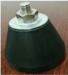
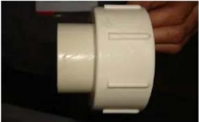
4.1 Accessories list
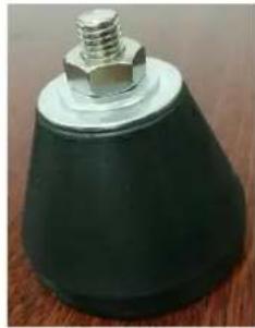
natural_image
Close-up of a black conical object with a metallic bolt and nut, resting on a wooden surface (no text or symbols visible)Anti-vibration base, 4 pcs

Draining plug, 2 pcs

natural_image
White plastic bag wrapped in a transparent container (no visible text or symbols)Winter Cover, 1 pc
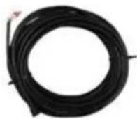
Modbus signal wire, 1 pc
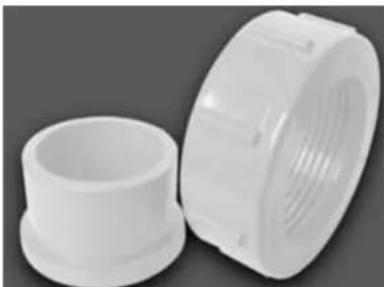
natural_image
Two white plastic pipe fittings, one cylindrical and one threaded, shown against a dark background (no text or symbols visible)Water connection assembly, 2 set
4.2 The By-Pass Kit (Not provided)
The By-Pass Kit is the essential accessory for the installation of your heat pump, it is also a tool for the optimization of the heating of the water. The valves allows the optimum flow of water using a manometer to make sure the optimized running of the compressor, see paragraph 5.6 controls of the pressure.
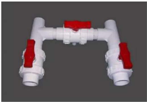
natural_image
3D rendering of a white PVC pipe fitting with red valve ports, no text or symbols visible4. Accessories and options
4.3 Accessories Installation
 | Anti-vibration bases1. Take out 4 Anti-vibration bases2. Install them on the bottom of machine. | ||
 | 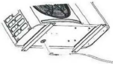 | Draining plug1. Install the draining plug under the bottom panel2. Connect with a water pipe to drain out the water.Note: Lift the heat pump to install the draining plug. Never overturn the heat pump, it could damage the compressor. | |
 |  | Water Inlet & outlet connection1. Install the two joints like the picture shows2. Screw them onto the water Inlet & outlet connection | |
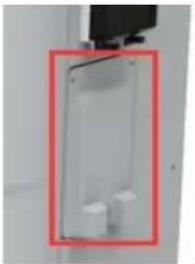 | 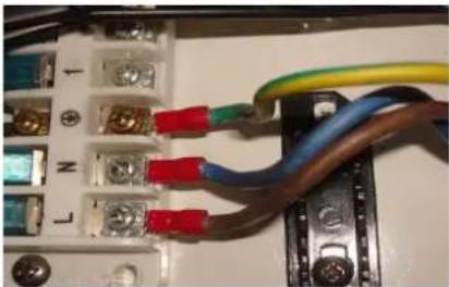 | Mains Cable wiring1. Open the cover of the terminal box (marked red) on the side of machine2. Tight the cables in the correct connections, L N E, inside the terminal block. | |
 |  | Filtration pump wiring (Dry contact1. Open the cover of the terminal box (marked red) on the side of machine2. Tight the cables in the correct connections, 1 2, inside the terminal block. | |
5. Location and connection
ATTENTION:
Please observe the following rules when installing the heat pump:
- Any addition of chemicals must take place in the piping located downstream from the heat pump.
- Always keep the heat pump upright. If the unit has been held at an angle, wait at least 24 hours before applying mains power to the heat pump.
5.1 Heat pump location
The unit will work properly in any desired location as long as the following three items are present:
-
Fresh air
-
Electricity
-
Swimming pool filters
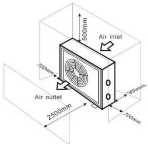
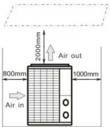
The unit may be installed in virtually any outdoor location as long as the specified minimum distances to other objects are maintained (see drawing below). Please consult your installer for installation with an indoor pool. Installation in a windy location does not present any problem at all.
ATTENTION:
- Never install the unit in a closed room with a limited air volume in which the air expelled from the will be reused, or close to shrubbery that could block the air inlet. Such locations impair the continuous supply of fresh air, resulting in reduced efficiency and possibly preventing sufficient heat output.
- When the appliance is installed and protected by a residual current device (RCD) with a maximum amperage of 30mA, it should be installed at a distance of at least 2 meters from the edge of the pool RCD is installed with the appliance, it should be installed at a distance of at least 3.5 meters from the of the pool.
5. Location and connection
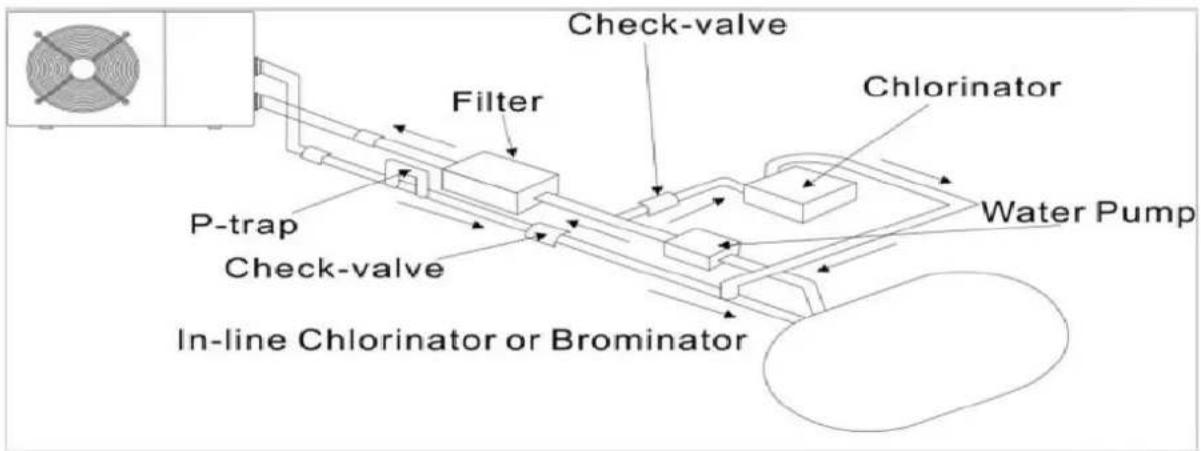
5.2 Check-valve installation

NOTE
Note: If automatic dosing equipment for chlorine and acidity (pH) is used, it is essential to protect the heat pump against excessively high chemical concentrations which may corrode the heat exchanger. For this reason, equipment of this sort must always be fitted in the piping on the downstream side of the heat pump, and it is recommended to install a check-valve to prevent reverse flow in the absence of water circulation. Damage to the heat pump caused by failure to observe this instruction is not covered by the warranty
5. Location and connection
5.3 Typical arrangement
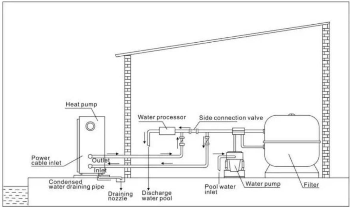
This arrangement is only an illustrative example.

NOTE
The factory supplies only the heat pump. All other components, including a bypass if necessary, must be provided by the user or the installer.
ATTENTION:
In order to heat the water in the pool (or hot tub), the filtration pump must be running so the is circulating through the heat pump. The heat pump will not start up if the water is not circula
5. Location and connection
5.4 Initial operation
After all connections have been made and checked, carry out the following procedure:
-
Switch on the filtration pump. Check for leaks and verify that water is flowing to and from the swimming pool.
-
Connect power to the heat pump and press the On/Off button in the electronic control panel. The unit will start up after the time delay expires (see below).
-
After a few minutes, check whether the air blowing out of the unit is cooler.
-
When the filtration pump is turned off, the unit should also turn off automatically.
-
Allow the heat pump and the filtration pump to run 24 hours a day until the desired water temperature is reached. The heat pump will stop running at this point +1°C. After this, it will restart automatically (as long as the filtration pump is running) whenever the swimming pool water temperature drops 1 degree below the set temperature (for example, if you set the temperature 28°C, the heat pump will stop when the temperature at 29°C. While it will restart when the temperature of the water down to 27°C)
Depending on the initial temperature of the water in the swimming pool and the air temperature, it may take several days to heat the water to the desired temperature. A good swimming pool cover can dramatically reduce the required length of time.

NOTE
Water Flow Switch:
It is equipped with a flow switch for protecting the HP unit running with adequate water flow rate. It will turn on when the filtration pump runs and shut it off when the pump shuts off.
Time delay - The heat pump has a built-in 3-minute start-up delay to protect the circuitry and avoid excessive electrical contactor wear. The unit will restart automatically after this time delay expires. Even a brief power interruption will trigger this time delay and prevent the unit from restarting immediately. Additional power interruptions during this delay period do not affect the 3-minute duration of the delay.
5. Location and connection
5.5 Condensation
The air drawn into the heat pump is cooled by the operation of the heat pump for heating the pool water, which may cause condensation on the fins of the evaporator.

NOTE
The amount of condensation may be as much as several liters per hour at high humidity. The condensate will drain from the bottom of the heat pump. This is sometimes mistakenly regarded as a water leak.
5.6 Pressure gauge display (R410A & R32)
Examine the pressure gauge which indicates the refrigerant gas pressure of the unit, the below table shows the normal value of the gas pressure (R410A & R32) when the machine is in power off or running conditions.
| Unit Condition | Power Off | |||
| Ambient (°C) | -5~5 | 5~15 | 15~25 | 25~35 |
| Water temp (°C) | / | / | / | / |
| Pressure gauge (Mpa) | 0.59~0.85 | 0.85~1.18 | 1.18~1.59 | 1.59~2.1 |
| Unit Condition | Running | ||||
| Ambient (°C) | / | / | / | / | / |
| Water temp (°C) | 10~15 | 15~20 | 20~25 | 25~30 | 30~35 |
| Pressure gauge (Mpa) | 1.1~1.6 | 1.3~1.8 | 1.5~2.1 | 1.7~2.4 | 1.9~2.7 |
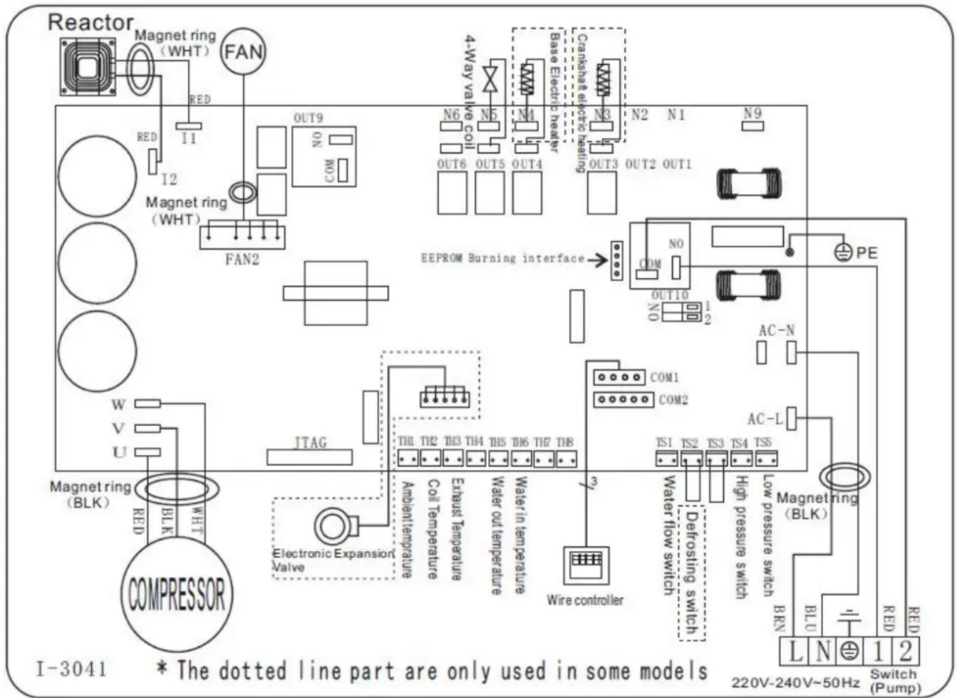
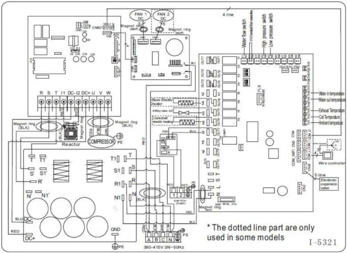
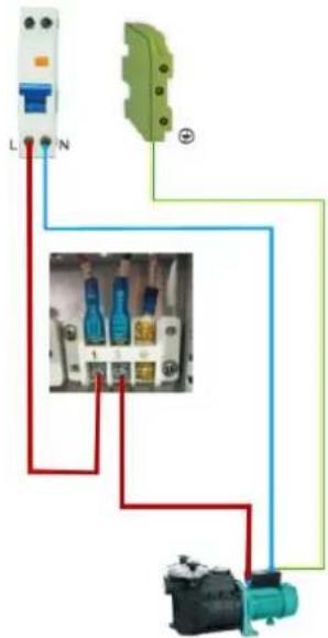
6. Electrical Wiring
6.1 Inverter swimming pool heat pump wiring diagram
Ref. 74166/ 74167/74168/74169/74170/74171
6. Electrical Wiring
6.2 Inverter swimming pool heat pump wiring diagram
Ref: 74172/74173
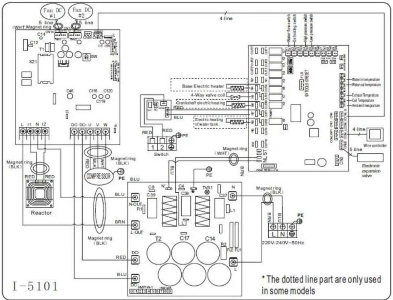
6. Electrical Wiring
6.3 Inverter swimming pool heat pump wiring diagram
Ref. 74174/74175 (R410A)
6.4 Connection to Modbus PCB
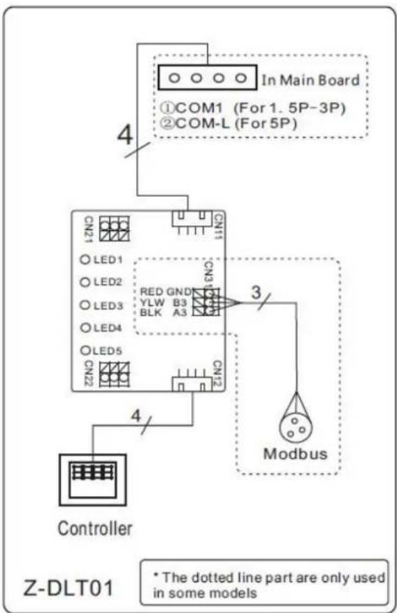
* Above electrical wiring diagram only for your reference, please subject machine posted the wiring diagram.
6.5 Electrical connection
The power supply for the heat pump must come, preferably, from an exclusive circuit with regulatory protection components (30mA differential protection) and a magneto-thermal switch.
- The electrical installation must be carried out by a specialized professional (electrician) in accordance with the standards and regulations in force in the country of installation.
- The heat pump circuit must be connected to a safety earth circuit at the terminal block.
- The cables must be properly installed to prevent interference.
- The pump is intended for connection to a general power supply with earth connection.
- Section of the cable; This section is indicative and should be checked and adapted according to the needs and conditions of use.
- The tolerance of acceptable voltage variation is +/- 10% during operation.
6. Electrical Wiring
The connections must be dimensioned according to the power of the device and the state of installation.
| Models | Circuit breaker | Maximum length of the wire | |||
| 2,5 mm^2 | 4 mm^2 | 6 mm^2 | 10 mm^2 | ||
| PET-08 | 7 A | 84 m | 135 m | 200 m | 335 m |
| PET-10 | 9 A | 57 m | 90 m | 130 m | 225 m |
| PET-13 | 11A | ||||
| PET-15 | 14 A | 43 m | 68 m | 100 m | 170 m |
| PET-19 | 16 A | 34 m | 54 m | 80 m | 135 m |
| PET-25 | 20 A | 29 m | 45 m | 66 m | 110 m |
| PET-30 | 26 A | / | 25 m | 38 m | 62 m |
| PET-30T | 10.5 A | 15 m | 35 m | 49 m | 81 m |
| PET-35 | 34 A | / | / | 22 m | 36 m |
| PET-35T | 13 A | 12 m | 27 m | 39 m | 68 m |
| These values are given as a guideline, only an authorized electrician can determine the va corresponding to your installation.The electric cable must be equipped with a ground connection and with a circuit breaker with differential 30mA. | |||||
6.6 Installation of the display deportee (option)
Photo(1) Photo(2) Photo(3) Photo(4) Photo(5)

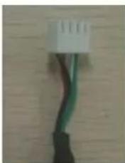
natural_image
Close-up of a black and green cable with a white connector (no text or symbols visible)

- The end with plug connects with the control panel (photo1)
- The other end of the signal wire. (photo2)
- Open the cover of the terminal box and pass through it the cable of the remote screen.(photo3,4)
- Insert the wiring into the designated position on the Modbus Module. (photo5)
6. Electrical Wiring
6.7 Installation of the Modbus/Fluidra Connect Signal Wire
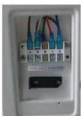
Photo(6) Photo(7) Photo(8) Photo(9)
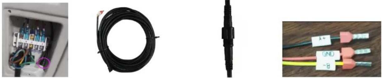
- Open the cover of the terminal box (photo6)
- Take the Modbus/Fluidra Connect signal wire from the accessories (photo7) and put the round end of the signal wire into the signal wire from Modbus/Fluidra Connect Module. (photo 8)
- Three wire terminal : "A+", "B-", "GND" (Photo 9)
6.8 Connection heating priority (option of running)
Dry contact timer connection
Timer

Dry contact pump connection
Water pump
7. Startup of the Health Project
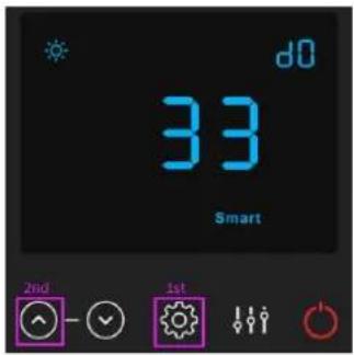
7. Display Controller Operation
7.1. Guide for operation
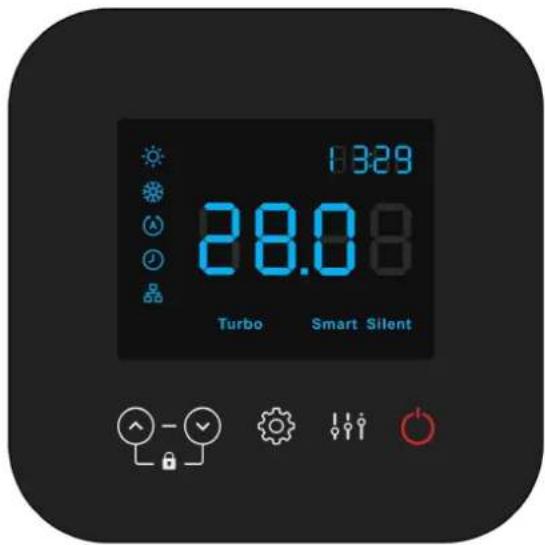
When the heat pump connects to the power, the display shows a code for 3 seconds which indicates the heat pum model.
7.2 The keys and their operations
7.2.1


Press the heat pump unit, the display shows the desired water temperature for 5 seconds, then shows the inlet water temperature and the operation mode.
Press to stop the heat pump unit and show "OFF"
Notice : During the parameter checking and setting, press the to quick-exit and save the current setting .
Press again to turn on/off the machine.
7.2.2

button

Lock/unlock the display:
Hold

5 s

to lock/Unlock the display.
The display will lock automatically after 30s of standby. (when the display is locked, the "locker" icon is lighted ON)
7. Start-up of the Heat Pump
Water temperature setting:


Press or to set the water temperature directly.
Heating mode and Auto mode setting range: 6-41°C
Cooling mode setting range: 6-35°C

7.2.3 button working mode

Press to change the working mode, Turbo, Smart and silent. The default mode is smart mode.
While you choose the Turbo, the word "Turbo" will be lit, the heat pump will operate in 'Full output' only.
Choose the Smart, the word "Smart" will be lit, the heat pump will operate in 'Medium and Full output'.
Choose the Silent, the word "Silent" will be lit, heat pump will operate in 'Medium and Small output'.

7.2.4 button mode

to switch the heating mode ,cooling mode and auto mode .


Remark: When defrosting, the heating symbol will flash.
Operation logic of Auto Mode:
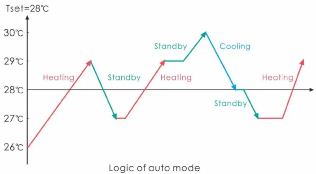
line
| Logic of auto mode | Tset=28°C | |---|---| | Heating | 26°C | | Standby | 27°C | | Heating | 29°C | | Standby | 28°C | | Cooling | 28°C | | Standby | 27°C | | Heating | 29°C |7. Start-up of the Heat Pump
7.2.5 Parameter checking
Press

press to ch

-d14 value.
| Code | Condition | Scope | Remark |
| d0 | IPM mould temperature | 0-120°C | Real testing value |
| d1 | Inlet water temp. | -9°C~99°C | Real testing value |
| d2 | Outlet water temp. | -9°C~99°C | Real testing value |
| d3 | Ambient temp. | -30°C~70°C | flash if Real value<-9 |
| d4 | Frequency limitation code | 0,1,2,4,8,16 | Real testing value |
| d5 | Piping temp. | -30°C~70°C | flash if Real value<-9 |
| d6 | Gas exhaust temprature | 0°C~C5°C (125°C) | Real testing value |
| d7 | Step of EEV | 0~99 | N*5 |
| d8 | Compressor running frequency | 0~99Hz | Real testing value |
| d9 | Compressor current | 0~30A | Real testing value |
| d10 | Current fan speed | 0-1200 (rpm) | Real testing value |
| d11 | Error code for last time | All error code | |
| d12 | MOBUS COM | 0 - 5 | Setting, Modbus Only |
| d13 | MODBUS ID Address | 1 - 88 | Setting, Modbus Only |
| d14 | Product Code | 0000- FFFF | Setting, Modbus Only |
Remark:
d4: Frequency limitation code,
0: No frequency limit; 1: Coil pipe temperature limit;
2: Overheating or overcooling frequency limit; 4:Drive Current frequency limit;
8:Drive voltage frequency limit; 16:Drive high temperature frequency limit
7. Start-up of the Heat Pump
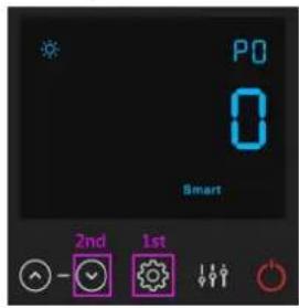
7.2.6 Parameter setting
Press when press to choose P18 value, and press again to enter the setting interface, in which parameter will flash.
| Code | Name | Scope | Default | Remark |
| P0 | Mandatory defrosting | 0-1 | 0 | 0: Default normal operation1: mandatory defrosting. |
| P1 | Working mode | 0-1 | 1 | 1: Heating mode, 0: cooling mode, |
| P2 | Timer on/off | 0-1 | 0 | 1 Timer on/off is under function Timer on/off is out of function (The setting of P5 and P6 won't work) |
| P3 | Water pump | 0-1 | 0 | 1: Always running;0: Depends on the running of compressor |
| P4 | Current time | HH:MM | 00: 00 | 0-23:0-59 |
| P5 | Timer on | HH:MM | 00: 00 | 0-23:0-59 |
| P6 | Timer off | HH:MM | 00: 00 | 0-23:0-59 |
| P7 | Water temp. calibration | -9~9 | 0 | Default setting: 0 |
| P12 | MOBUS COM | 0 - 5 | 0 | Modbus Only (default value after reset |
| P13 | MODBUS ID Address | 1 - 88 | 9 | Modbus Only (default value after reset |
| P14 | Restore to factory settings | 0-1 | 0 | 1-Restore to factory settings0- default (restore P0, P1, P2, P3, P5, P6, P7, P8, 10, P11 to factory setting) |
| P15 | Parameter P value for Modbus | / | / | Depends on the machine(Modbus Only) |
| P16 | Product code | / | / | Depends on the machine |
| P18 | Mode | 0-1 | 0 | 1—Heating only,0—Heating/Cooling/Auto mode |
Note:
1). Long press for 20s to set P14, P16, P18.
2). P8,P9,P10,P11,P19,P20 parameter is only for factory setting.
7. Start-up of the Heat Pump
| Code with connect | Parameter P value for Modbus | Description |
| 74166 | 21b6 | PAC PROELYO TOUCHET-08 |
| 74167 | 21b7 | PAC PROELYO TOUCHET-10 |
| 74168 | 21b8 | PAC PROELYO TOUCHET-13 |
| 74169 | 21b9 | PAC PROELYO TOUCHET-15 |
| 74170 | 21ba | PAC PROELYO TOUCHET-19 |
| 74171 | 21bb | PAC PROELYO TOUCHET-25 |
| 74172 | 21bc | PAC PROELYO TOUCHET-30 |
| 74173 | 21bd | PAC PROELYO TOUCHET-35 |
| 74174 | 21be | PAC PROELYO TOUCHET-30T |
| 74175 | 21bf | PAC PROELYO TOUCHET-35T |
Steps to set Parameter P value for Modbus (Modbus Only):
The symbol is the display is on when the modbus module is connected to the display.
Press when press to choose P15, and long press for 20s to enter the setting interface,
in which parameter will flash. Press to set correct value, finally press to save settings.
7.2.7 System reset function
Press , then press to choose P14, and enter into the value setting interface by long press

for 20s, in which parameter will flash. Prior to the value 1, finally press

to save settings.
7.2.8

Symbol of TIMER ON, the light will be on when the value of P2 is 1, which means TIME ON & OFF function is working. Then set the current time (Parameter P4), TIMER ON (Parameter P5) and TIMER OFF (Parameter P6). All the symbols (except symbol) on the display will be off when TIMER is OFF.
Note: The symbols on when restart the heat pump after TIME OFF, unless the value of P2 is set to 0.
7. Start-up of the Heat Pump
7.2.9 System filtration pilot function
Option 1; P3=0 Filtration pump is related to heat pump operation to start and stop.
Filtration pump starts 60s before compressor, filtration pump start 30s and then the water flow switch detect flow. Before the heat pump enters into Standby mode, the compressor stops first and after 5 minutes filtratio pump stops.
| Condition | Example | Water pump working logic | ||
| Heating mode | P3=0,T1≥Tset-0.5°C, last for 30 minutes | P3=0,T1≥27.5°C, last for 30 minutes | 1. Then it enters into standby mode for 1 hour (It will not restart except turn it on manually.) | 2. After 1 hour, the filtration pum will restart for 5 minutes. If the T1≤27°C, the heat pump will start to work until T1≥27.5°C and last 30 minutes to go into standby |
| Cooling mode | P3=0,T1≤Tset+0.5°C, last for 30 minutes | P3=0,T1≤28.5°C, last for 30 minutes | 1. Then it enters into standby mode for 1 hour (It will not restart except turn it on manually.) | 2. After 1 hour, the filtration pum will restart for 5 minutes. If it test T1≥29°C, the heat pump will start to work until T1≤28.5°C and last 30 minutes to go into standby |
Option 2; P3=1 Filtration pump is always on, P2=0 the timer function is no active
Under condition P3=1, when T1≥Tset+1°C (T1≥29°C) last for 3 minutes, heat pump will be in standby, while filtration pump is always on.
Under option 2, with activation of the timer; P2=1 to start and stop the filtration pump according to the programming of the P4 (time), P5 (timer ON) and P6 (timer OFF)
Condition for the heat pump start, timer ON actives;
When the timer reaches the set time of TIMER ON, the filtration pump will start and after 5 minutes the heat pump start. The heat pump stays in stop if the water in temperature is ≥ T_set+1^ , before the TIMER OFF, the filtration is still activated.
Condition to stop the heat pump, timer OFF actives;
When the timer reaches the set time of the TIMER OFF, the heat pump will stop and after 5 minutes the filtration pump stops.
If heat pump is turned ON/OFF manually, the filtration pump will start and stop accordingly.
NOTE :
Tset = Tsetting water temperature
For example: Tset = 28°C Tsetting water temperature in your pool heat pump
Tset-0.5 = less 0.5°C than Tsetting temperature, Tset-0.5 = 28-0.5=27.5°C
Tset+0.5= more 1°C than Tsetting temperature, Tset+ 0.5 = 28+0.5=28.5°C
7. Start-up of the Heat Pump
7.3 Heating operation logic
| Working status | Working mode | Water in temperature-T1 | For example, water in temperature-T1 | Heat pump working level | |
| 1 | Start-up of heat pump | When you select the "Smart working mode" | T1< Tset-1 | T1< 27°C | Powerful mode-frequency F9 |
| 2 | Tset-1≤T1 < Tset | 27°C≤T1 <28°C | Frequency: F9 -F8-F7,...,-F2 | ||
| 3 | Tset≤ T1 <Tset+ 1 | 28°C≤ T1 <29°C | Silent mode-frequency F2 | ||
| 4 | T1≥Tset+1 | T1≥29°C | HP will be in Standby, stop working until the water temperature drops to less 28°C | ||
| 5 | When you select the "Silent working mode". | T1< Tset | T1< 28°C | Smart mode -frequency F5. | |
| 6 | Tset≤T1 < Tset+1 | 28°C≤T1 < 29°C | Silent mode-frequency F2/F1. | ||
| 7 | T1≥Tset+1 | T1≥29°C | HP will be in Standby, stop working until the water temperature drops to less 28°C | ||
| 8 | When you select the "Powerful working mode." | T1<Tset+1 | T1<29°C | Powerful mode-frequency F10/F9 | |
| 9 | T1≥ Tset+1 | T1≥29°C | HP will be in Standby, stop working until the water temperature drops to less 28°C | ||
| 10 | Re-start to heat water in standby status | When HP is working at " Smart mode" | T1≥Tset | T1≥28°C | Standby |
| 11 | Tset>T1≥Tset-1 | 28°C>T1≥27°C | Silent-frequency F2 | ||
| 12 | Tset-1>T1≥Tset-2 | 27°C>T1≥26°C | Frequency: F2 -F3-F4,...,-F9 | ||
| 13 | <Tset-2 | <26°C | Powerful-frequency F9 | ||
| 14 | When HP is working at " Silent mode" | ≥Tset | ≥28°C | Standby | |
| 15 | Tset>T1≥Tset-1 | 28°C>T1≥27°C | Silent mode-frequency F2/F1 | ||
| 16 | T1<Tset-1 | T1<27°C | Smart -frequency F5 | ||
| 17 | When HP is working at " Powerful mode" | T1<Tset-1 | T1<27°C | Powerful -frequency F10/F9 | |
7. Start-up of the Heat Pump
7.4 Cooling operation logic
| Working status | Working mode | Water in temperature | For example, wate in temperature | Heat pump working level | |
| 1 | Start-up of heat pump | When you select the "Smart working mode" | T1 ≦ Tset-1 | T1 ≦ 27°C | Standby. |
| 2 | Tset-1<T1 ≦ Tset | 27°C< T1 ≦ 28°C | Silent mode-frequency F2 | ||
| 3 | Tset<T1 ≦ Tset+1 | 28< T1 ≦ 29°C | frequency: F9 -F8-F7,...,- F2 | ||
| 4 | T1 ≦ Tset+1 | T1 ≦ 29°C | Powerful mode-F9 | ||
| 5 | When you select the "Silent working mode". | T1 ≦ Tset-1 | ≤ 27°C | Standby | |
| 6 | Tset-1<T1 ≦ Tset | 27°C< T1 ≦ 28°C | Silent mode - frequency F2/F | ||
| 7 | T1>Tset | T1>28°C | Smart mode -frequency F5 | ||
| 8 | When you select the "Powerful working mode." | T1>Tset-1 | T1>27°C | Powerful mode-frequency F10/F9 | |
| 9 | T1 ≦ Tset-1 | T1 ≦ 27°C | Standby | ||
| 10 | Re-start to cool water in standby status | Smart | T1 ≦ Tset-1 | T1 ≦ 27°C | Standby |
| 11 | Tset ≦ T1 <Tset+1 | 28 ≦ T1 <29°C | Silent- frequency F2 | ||
| 12 | Tset+1 ≦ T1 <Tset+2 | 29 ≦ T1 <30°C | Frequency: F2 -F3-F4,...,- F9 | ||
| 13 | T1 ≦ Tset+2 | T1 ≦ 30°C | Powerful mode -frequency F9 | ||
| 14 | Silent | Tset<T1 ≦ Tset+1 | 28< T1 ≦ 29°C | Silent mode-frequency F2/F1 | |
| 15 | T1 >Tset+1 | T1>29°C | Smart mode-frequency F5 | ||
| 16 | Powerful | T1 >Tset+1 | T1>29°C | Powerful mode-frequency F10/F9 | |
| 17 | T1 ≦ Tset-1 | T1 ≦ 27°C | Standby | ||
8. Troubleshooting
8.Troubleshooting
8.1 Error code display on LED wire controller
| Malfunction | Error code | Reason | Solution |
| Inlet water temperature sensor failure d1-TH6 | PP01 | 1. The sensor in open or short circ2. The wiring of sensor is loose | 1. Check or change the sensor2.Re-fix the wiring of the sensors |
| Outlet water temperature sensor failure d2-TH5 | PP02 | 1. The sensor in open or short circ2. The wiring of sensor is loose | 1. Check or change the sensor2.Re-fix the wiring of the sensors |
| Heating piping sensor failure d5-TH2 | PP03 | 1. The sensor in open or short circ2. The wiring of sensor is loose | 1. Check or change the sensor2.Re-fix the wiring of the sensors |
| Ambient temperature sensor failure d3-TH1 | PP05 | 1. The sensor in open or short circ2. The wiring of sensor is loose | 1. Check or change the sensor2.Re-fix the wiring of the sensors |
| Exhaust piping sensor failure d6-TH3 | PP06 | 1. The sensor in open or short circ2. The wiring of sensor is loose | 1. Check or change the sensor2.Re-fix the wiring of the sensors |
| Antifreeze protection in Winter | PP07 | Ambient temperature or water inlet temperature is too low | 1. Check the d1((inlet water temp.) and d3(outlet water temp.)2. Normal protection |
| Low ambient temperature protection | PP08 | 1. Out of the normal operating ambient temperature for this machine by checking d32. Sensor abnormality d3-TH1 | 1. Stop using, beyond the scope of using2.Change the sensor |
| Piping temperature too high protection under cooling mode d5-TH2 | PP10 | 1. Ambient or the water temperatu is too high in cooling mode2. Refrigeration system is abnormal3. Pipe temperature sensor(d5-TH2) failure | 1. Check the ambient temperature2. Check refrigeration system3. Change the pipe temperature sensor (d5-TH2) |
| Over low protection for outlet water temperature in cooling mode d2-TH5 | PP11 | 1. Low water flow2. Outlet water temperature sensor d2-TH5 abnormal3. The difference of outlet water temperature and set temperature is 7°C or above in cooling mode | 1. Check filtration pump and waterway system2. Change outlet water temperature sensor d2-TH53. Change the set temperature. |
| High pressure failure TS4 | EE01 | 1. Ambient temperature is too high2. Water temperature is too high3. Water flow is too low4. Fan motor speed is abnormal or fan motor is damaged under cooling mode5. Gas system jammed6. High pressure wire is loose or damaged7. Too much refrigerant | 1. Choose the silent mode.2. Check the water flow or filtration pu3. Check the fan motor under cooling mode, replace a new one if it is abnorr4. Check and repair the refrigerating system5. Reconnect the high pressure wire or replace a new high pressure switch6. Check and repair the refrigerating system |
8. Troubleshooting Troubleshooting
| Malfunction | Error code | Reason | Solution |
| Low pressure failure TS5 | EE02 | 1. EEV has blocked or pipe system is jammed2. Fan motor speed is abnormal or fan motor is damaged under heating mode3. Gas leakage4. Low pressure wire is loose or damaged | 1. Check the EEV and piping system2. Check the fan motor under heating mode, replace a new one if it is abnormal3. Check refrigeration system or check the pressure value through the high-pressure gauge.4. Reconnect the low pressure wire or replace a new low pressure switch |
| Water flow failure TS1 | EE03 Or "ON" | 1. The wiring of water flow switch is loose or water flow switch damaged2. No/Insufficient water flow. | 1. Check the wiring of water flow switch change a new one.2. Check the filtration pump or the waterway system if there is air or jam inside |
| Over heating protection for water temperature (d2- TH5) in heating mode | EE04 | 1. Low water flow2. Water flow switch is stuck and the water supply stops3. d2- TH5 outlet water temperature sensor is abnormal4. The difference of outlet water temperature and set temperature is 7°C or above in heating mode | 1. Check the water flow switch if it wor well2. Check the filtration pump or the waterway system if there is air or jam inside3. Check d2- TH5 outlet water temperature sensor or replace a new on4. Change the set temperature. |
| d6-TH3 Exhaust too high protection | EE05 | 1. Lack of gas2. Low water flow3. Piping system has been blocked4. Exhaust temp. sensor failure d6-TH35. Ambient temperature is too high | 1. Check the pressure gauge, and fill with some gas if it is lack of gas2. Check the filtration pump or the waterway system if there is air or jam inside3. Check the piping system if there was any block4. Change a new exhaust temp. sensor d6-TH35. Check whether the current ambient temp. and water temp. are beyond the running temp. of the machine |
| Controller failure | EE06 | 1. Signal is not well connected or damaged2. Controller failure | 1. Stop the power supply and restart.2. Re-connect the signal wire or replace new one3. Replace a new controller |
8. Troubleshooting
| Malfunction | Error code | Reason | Solution |
| Compressor current protection | EE07 | 1. The compressor current is too large instantaneously2. Wrong connection for compressor phase sequence3. Compressor accumulations of liquid and oil lead to the current becomes larger4. Compressor or driver board damaged5. The water flow is abnormal6. Power fluctuations within a short tim | 1. Check if the power in the normal ran2. Check the compressor3. Check the compressor phase4. Check the phase sequence connection5. Check the waterway system and filtration pump6. Check mains power input |
| Communication failure between controller and main board | EE08 | 1. Signal wire is not well connected or damaged2. Controller failure3. Driving failure | 1. Stop the power supply and restart.Re-connect the signal wire or replace a new one2. Check the controller or replace a new one3. Check the driving system or update |
| Communication failure between Main control board and Driving board | EE09 | 1. Poor connection of communication wire2. PCB failure3. The wire is damaged | 1. Stop the power supply and restart.2. Reconnect the communication wire or replace a new one3. Check the wirings according to the electric diagram4. Replace a new PCB |
| VDC voltage too high protection | EE10 | 1. Line voltage is too high2. Driver board is damaged. | 1. Check whether the power supply is normal2. Change driver board or main board |
| IPM module protection | EE11 | 1. Data mistake2. Wrong compressor phase connection3. Compressor liquid and oil accumulation lead to the current becomes larger4. Poor heat dissipation of drive module or high ambient temperature5. Compressor or driver board damaged | 1. Program error, turn off electricity supply and restart after 3 minutes2. Check compressor sequence connection3. Check the pressure of system by pressure gauge4. Check if the ambient and water temperature is over high5. If it is the refrigeration system failure send it to the service center6. Change driver board |
| VDC voltage too low protection | EE12 | 1. Mother line voltage is too low2. Driver board is damaged. | 1. Check if the power supply is in the normal range2. Change driver board |
8. Troublesboditingg
| Malfunction | Error code | Reason | Solution |
| Input current over high protection. | EE13 | The compressor current is too large momentaryThe water flow is abnormalPower fluctuations within a short timeWrong reactor | Check the compressor if it works normallyCheck the waterway systemCheck if the power is in the normal raCheck if the reactor is used correctly. |
| IPM module thermal circuit is abnormal | EE14 | Output abnormality of IPM module thermal circuitFan motor is abnormal or damagFan blade is broken | Check if the motor speed is too low of fan motor is damaged, replace it by a ne one.Replace a new driver boardChange the fan blade if it is broken |
| IPM module temperature too high protection | EE15 | Output exception of IPM module thermal circuitFan motor is abnormal or damagFan blade is brokenThe screw on driver board is loose | Check the main board or replace the driver boardCheck if the motor speed is too low of fan motor is damaged, replace it by a ne one if any failure.Change the fan blade if it is brokenCheck the screw on driver board |
| PFC module protection | EE16 | Output exception of PFC moduleFan motor is abnormal or damagFan blade is brokenInput voltage leap, input power is abnormal | Check the main board or replace the driver boardCheck if the motor speed is too low of fan motor is damaged, replace it by a ne one.Change the fan bladeCheck the input voltage |
| DC fan motor failure | EE17 | DC motor is damagedFor the tri-phase check if the neutral is connectedMain board is damagedThe fan blade is stuck | Detect DC motor for mono phase machine, replace a new one if any failureCheck the wiring connection for tri-pha machineCheck the board, replace a new driver board or main board if any failureCheck if there is any barrier in front of fan blade and remove it |
| PFC module thermal circuit is abnormal | EE18 | The driver board is damaged | Check if the motor speed is too low of fan motor is damaged, replace it by a ne one.Change a new driver board |
8. Troubleshooting
| Malfunction | Error code | Reason | Solution |
| PFC module high temperature protection | EE19 | 1. PFC module thermal circuit output abnormal2. Fan motor is abnormal or damaged3. Fan blade is broken4. The screw in the driver board is not tight | 1. Check the main board or replace the driver board2. Check if the motor speed is too low or fan motor is damaged, replace it b new one if any failure.3. Change the fan blade if it is broken4. Check the screw on driver board |
| Input power failure | EE20 | The supply voltage fluctuates too much | Check whether the voltage is stable |
| Software control exception | EE21 | 1. Compressor runs out of step2. Wrong program3. Impurity inside compressor causes the unstable rotate speed | 1. Check the main board or change a new one2. Update the correct program3. Check the refrigeration system |
| Current detection circuit failure | EE22 | 1. Voltage signal abnormal2. Driver board is damaged3. Main board failure | 1. Change a new main board2. Change a new driver board |
| Compressor start failure | EE23 | 1. Main board is damaged2. Compressor wiring error or poor contact or unconnected3. Liquid accumulation inside4. Wrong phase connection for compressor | 1. Check the main board or change a new one2. Check the compressor wiring according to the circuit diagram3. Check the compressor or change a new one |
| Ambient Temperature device failure on Driver board | EE24 | Ambient Temperature device failure | Change driver board or main board |
| Compressor phase failure | EE25 | Compressors U, V, W are just connected one phase or two phases. | Check the actual wiring according to t circuit diagram |
| Four-way valve reversal failure | EE26 | 1. Four-way valve reversal failure2. Lack of refrigerant (no detect when d5-TH2 or d3-TH1 malfunction) | 1. Switch to Cooling mode to check th 4-way valve if it has been reversed correctly2. Change a new 4-way valve3. Fill with gas |
| EEPROM data read malfunction | EE27 | 1. Wrong EEPROM data in the program failed input of EEPROM data2. Main board failure | 1. Re-enter correct EEPROM data2. Change a new main board |
| The inter-chip communication failure on the main control board | EE28 | Main board failure | 1. Stop electricity supply and restart it2. Change a new main board |
Remarks:
- In heating mode, if the water out temperature is higher than the set temperature over 7^ C, LED controller displays EE04 for water over-heating protection.
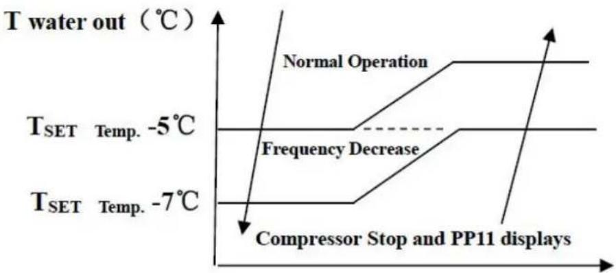
- In cooling mode, if the water out temperature is lower than the set temperature over 7^ C, LED controller displays PP11 for water over-cooling protection.

line
| Condition | Temperature (°C) | |---|---| | Compressor Stop and EE04 displays | T_SET Temp. +7°C | | Compressor Stop and EE04 displays | T_SET Temp. +5°C | | Frequency Decrease | T_SET Temp. +5°C | | Normal Operation | T_SET Temp. +5°C |EE04 Water Overheating Protection
line
| Condition | Temperature (°C) | |---|---| | Normal Operation | 0 | | Compressor Stop and PP11 displays | -7 | | Frequency Decrease | -5 | T_SET Temp. -5°C | T_SET Temp. -5°C | T_SET Temp. -7°C | T_SET Temp. -7°C |PP11 Water Overcooling Protection
For example as below:
| Mode | Output water temperature | Set point temperature | Condition | Malfunction |
| Heating mode | 36°C | 29°C | Tout -Tset ≧7°C | EE04 Overheating protection for water temperature (d2- TH5) |
| Cooling mode | 23°C | 30°C | Tset -Tout ≧7°C | PP11 Too low protection for water temperature (d2- TH5) |
8. Troubleshooting
8.2 Other Malfunctions and Solutions (No display on LED wire controller)
| Malfunctions | Observing | Reasons | Solution |
| Heat pump is not running | LED wire controller no display. | No power supply | Check cable and circuit breaker if it connected |
| LED wire controller.Displays the actual time. | Heat pump under standby status | Startup heat pump to run. | |
| LED wire controller displays the actual water temperature. | 1. Water temperature is reaching to setting value, HF under constant temperature status.2. Heat pump just starts to run.3. Under defrosting. | 1. Verify water temperature setting.2. Startup heat pump after a few minutes.3. LED wire controller should display "Defrosting". | |
| Water temperature is cooling when HP runs under heating mode | LED wire controller displays actual water temperature and no error code displays. | 1. Choose the wrong mode.2. Figures show defects.3. Controller defect. | 1. Adjust the mode to proper runni2. Replace the defect LED wire controller, and then check the statu after changing the running mode, verifying the water inlet and outlet temperature.3. Replace or repair the heat pump unit |
| Short running | LED displays actual water temperature, no error code displays. | 1. Fan NO running.2. Air ventilation is not enough.3. Refrigerant is not enough. | 1. Check the cable connections between the motor and fan, if necessary, it should be replaced.2. Check the location of heat pump unit, and eliminate all obstacles to make good air ventilation.3. Replace or repair the heat pump unit. |
| Water stains | Water stains on heat pump unit | 1. Concreting.2. Water leakage. | 1. No action.2. Check the titanium heat exchange carefully if it is any defect. |
| Too much ice on evaporator | Too much ice on evaporator. | 1. Check the location of heat pump unit, and eliminate all obstacles to make good air ventilation.2. Replace or repair the heat pump unit. |
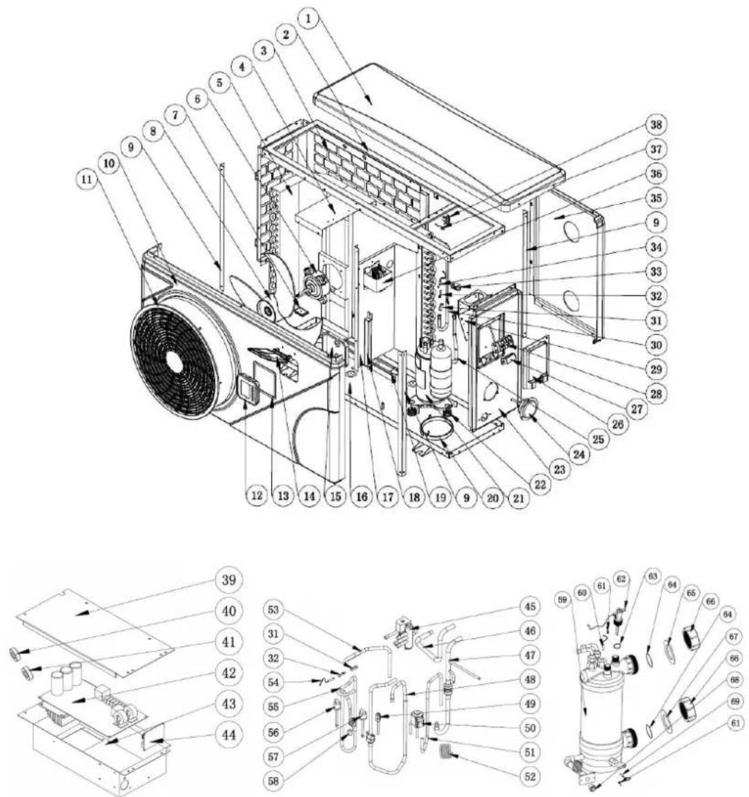
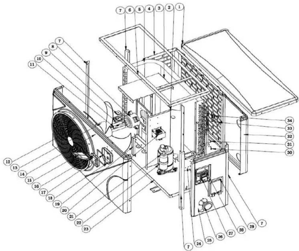
9. Exploded Diagram
9. 1 Exploded Diagram
Mode: 74166
9. Exploded Diagram
9.2 Spare Parts list
Model : 74166
| NO | ERP | Spare parts | NO | ERP | Spare parts |
| 1 | 133050118 | Top cover | 36 | 117230003 | Reactor |
| 2 | 180140092 | Top frame | 37 | 117110020 | Ambient temp. sensor d3-TH1 |
| 3 | 180140113 | Left side panel | 38 | 133020010 | Ambient temp. sensor clip |
| 4 | 180140100 | Fan motor bracket | 39 | 108030059 | Electric box cover |
| 5 | 103000227 | Evaporator | 40 | 117240002 | Magnet ring |
| 6 | 112000031 | Fan motor | 41 | 117240003 | Magnet ring |
| 7 | 108480015 | Evaporator heating resistor support | 42 | 117100046 | PCB |
| 8 | 132000015 | Fan blade | 43 | 108030095 | Electric box |
| 9 | 180140093 | Pillar | 44 | 117020239 | Modbus module |
| 10 | 133050115 | Front panel | 45 | 121000035 | 4 way valve |
| 11 | 133020077 | Fan grill | 46 | 113030192 | 4-way valve to exchanger |
| 12 | 117020293 | Controller | 47 | 113070042 | Exchanger to EEV |
| 13 | 136010072 | Sealing ring | 48 | 113020320 | Gas return piping |
| 14 | 133020096 | Controller cover | 49 | 120000098 | Gas valve |
| 15 | 133020097 | Controller box | 50 | 119000058 | EEV |
| 16 | 180140091 | Base tray | 51 | 113080074 | EEV to distribution piping |
| 17 | 180140099 | Isolation panel | 52 | 109000044 | Capillary |
| 18 | 180140101 | Panel support | 53 | 113060123 | Tube |
| 19 | 142000143 | Evaporator heating resistor | 54 | 117110021 | Discharge temp. sensor d6-TH3 |
| 20 | 142000072 | Compressor heating resistor | 55 | 113010229 | Discharge pipe |
| 21 | 101000187 | Compressor | 56 | 112100030 | High pressure switch |
| 22 | 101000187 | Compressor damping feet | 57 | 112100046 | Low pressure switch |
| 23 | 133050116 | Right panel | 58 | 113100024 | Coupling tube |
| 24 | 106000011 | Pressure gauge | 59 | 102041058 | Titanium heat exchanger |
| 25 | 103000227 | Evaporator pipe | 60 | 117110011 | Water outlet temp. sensor d2-TH5 |
| 26 | 133250005 | Terminal blocks plastic cover | 61 | 108010025 | Exchanger temperature sensor clip |
| 27 | 136010004 | Clip | 62 | 112100021-1 | Water flow switch |
| 28 | 115000004 | 5-ways terminal block | 63 | 116000001 | Sealing ring |
| 29 | 108010065 | Terminal board | 64 | 133020026 | Rubber ring on water connection |
| 30 | 103000227 | Distribution piping | 65 | 133020012 | Red rubber ring |
| 31 | 113190001 | Sensor holder | 66 | 113900082 | Water connection sets |
| 32 | 113190007 | Clip | 67 | 133020011 | Blue rubber ring |
| 33 | 136020018 | Rubber block | 68 | 150000110 | Drainage plug |
| 34 | 117110004 | Evaporator temperature sensor d5-TH2 | 69 | 117110012 | Water inlet temp. sensor d1-TH6 |
| 35 | 133050117 | Back panel |
9. Exploded Diagram
9.3 Model: 74167/74168/74169

9. Exploded Diagram
9.4 Spare parts list: 74167
| NO | ERP | Spare parts | NO | ERP | Spare parts |
| 1 | 133090073 | Top cover | 35 | 113030086 | 4-way valve to exchanger |
| 2 | 108110094 | Isolation panel | 36 | 120000097 | Gas valve |
| 3 | 108110095 | Fan motor bracket | 37 | 113020527 | Gas return piping |
| 4 | 108110113 | Left side panel | 38 | 112100046 | Low pressure switch |
| 5 | 103000221 | Evaporator | 39 | 112100030 | High pressure switch |
| 6 | 108110091 | Top frame | 40 | 113010210 | Discharge pipe |
| 7 | 108110092 | Pillar | 41 | 117110021 | Discharge temp. sensor d6-TH3 |
| 8 | 112000031 | Fan motor | 42 | 113190001 | Sensor holder |
| 9 | 108480015 | Evaporator heating resistor support | 43 | 119000058 | EEV |
| 10 | 142000142 | Evaporator heating resistor | 44 | 121000037 | Coil for 4 way valve |
| 11 | 108010024 | Fan shaft cover | 45 | 121000034 | 4 way valve |
| 12 | 133020078 | Fan grill | 46 | 113060084 | Tube |
| 13 | 132000015 | Fan blade | 47 | 113080054 | EEV to distribution piping |
| 14 | 133090070 | Front panel | 48 | 113070044 | Exchanger to EEV |
| 15 | 133020096 | Controller cover | 49 | 109000044 | Capillary |
| 16 | 117020293 | Controller | 50 | 102041060 | Titanium heat exchanger |
| 17 | 136010072 | Sealing ring | 51 | 117110011 | Water outlet temp. sensor d2-TH5 |
| 18 | 133020097 | Controller box | 52 | 113190008 | Exchanger temperature sensor clip |
| 19 | 108110096 | Panel support | 53 | 112100021-1 | Water flow switch |
| 20 | 117230003 | Reactor | 54 | 136020083 | Sealing ring |
| 21 | 101000188 | Compressor | 55 | 133020026 | Rubber ring on water connection |
| 22 | 142000072 | Compressor heating resistor | 56 | 133020012 | Red rubber ring |
| 23 | 108110103 | Base tray | 57 | 113900082 | Water connection sets |
| 24 | 108010065 | Terminal board | 58 | 133020011 | Blue rubber ring |
| 25 | 133090071 | Right panel | 59 | 150000110 | Drainage plug |
| 26 | 106000011 | Pressure gauge | 60 | 117110012 | Water inlet temp. sensor d1-TH6 |
| 27 | 136010004 | Clip | 61 | 108010025 | Exchanger temperature sensor clip |
| 28 | 115000004 | 5-ways terminal block | 62 | 110000013 | Rubber ring |
| 29 | 133250005 | Terminal blocks plastic cover | 63 | 108110045 | Electric box |
| 30 | 113190007 | Sensor holder | 64 | 117020239 | Modbus module |
| 31 | 117110004 | Evaporator temperature sensor d5-TH2 | 65 | 117100046 | PCB |
| 32 | 133090072 | Back panel | 66 | 117240002 | Magnet ring |
| 33 | 117110020 | Ambient temp. sensor d3-TH1 | 67 | 117240003 | Magnet ring |
| 34 | 133020010 | Ambient temp. sensor clip | 68 | 108050017 | Electric box cover |
9.5 Spare parts list: 74168
| NO | ERP | Spare parts | NO | ERP | Spare parts |
| 1 | 133090073 | Top cover | 35 | 113030081 | 4-way valve to exchanger |
| 2 | 108110094 | Isolation panel | 36 | 120000097 | Gas valve |
| 3 | 108110095 | Fan motor bracket | 37 | 113020527 | Gas return piping |
| 4 | 108110113 | Left side panel | 38 | 112100046 | Low pressure switch |
| 5 | 103000182 | Evaporator | 39 | 112100030 | High pressure switch |
| 6 | 108110091 | Top frame | 40 | 113010210 | Discharge pipe |
| 7 | 108110092 | Pillar | 41 | 117110021 | Discharge temp. sensor d6-TH3 |
| 8 | 112000031 | Fan motor | 42 | 113190001 | Sensor holder |
| 9 | 108480015 | Evaporator heating resistor support | 43 | 119000058 | EEV |
| 10 | 142000142 | Evaporator heating resistor | 44 | 121000037 | Coil for 4 way valve |
| 11 | 108010024 | Fan shaft cover | 45 | 121000034 | 4 way valve |
| 12 | 133020078 | Fan grill | 46 | 113060084 | Tube |
| 13 | 132000015 | Fan blade | 47 | 113080054 | EEV to distribution piping |
| 14 | 133090070 | Front panel | 48 | 113070041 | Exchanger to EEV |
| 15 | 133020096 | Controller cover | 49 | 109000044 | Capillary |
| 16 | 117020293 | Controller | 50 | 102041059 | Titanium heat exchanger |
| 17 | 136010072 | Sealing ring | 51 | 117110011 | Water outlet temp. sensor d2-TH5 |
| 18 | 133020097 | Controller box | 52 | 113190008 | Exchanger temperature sensor clip |
| 19 | 108110096 | Panel support | 53 | 112100021-1 | Water flow switch |
| 20 | 117230003 | Reactor | 54 | 136020083 | Sealing ring |
| 21 | 101000188 | Compressor | 55 | 133020026 | Rubber ring on water connection |
| 22 | 142000072 | Compressor heating resistor | 56 | 133020012 | Red rubber ring |
| 23 | 108110103 | Base tray | 57 | 113900082 | Water connection sets |
| 24 | 108010065 | Terminal board | 58 | 133020011 | Blue rubber ring |
| 25 | 133090071 | Right panel | 59 | 150000110 | Drainage plug |
| 26 | 106000011 | Pressure gauge | 60 | 117110012 | Water inlet temp. sensor d1-TH6 |
| 27 | 136010004 | Clip | 61 | 108010025 | Exchanger temperature sensor clip |
| 28 | 115000004 | 5-ways terminal block | 62 | 110000013 | Rubber ring |
| 29 | 133250005 | Terminal blocks plastic cover | 63 | 108110045 | Electric box |
| 30 | 113190007 | Sensor holder | 64 | 117020239 | Modbus module |
| 31 | 117110004 | Evaporator temperature sensor d5-TH2 | 65 | 117100047 | PCB |
| 32 | 133090072 | Back panel | 66 | 117240002 | Magnet ring |
| 33 | 117110020 | Ambient temp. sensor d3-TH1 | 67 | 117240003 | Magnet ring |
| 34 | 133020010 | Ambient temp. sensor clip | 68 | 108050017 | Electric box cover |
89 Exploded Diagram
9.6 Spare parts list: 74169
| NO | ERP | Spare parts | NO | ERP | Spare parts |
| 1 | 133090073 | Top cover | 35 | 113030081 | 4-way valve to exchanger |
| 2 | 108110094 | Isolation panel | 36 | 120000097 | Gas valve |
| 3 | 108110095 | Fan motor bracket | 37 | 113020321 | Gas return piping |
| 4 | 108110113 | Left side panel | 38 | 112100046 | Low pressure switch |
| 5 | 103000220 | Evaporator | 39 | 112100030 | High pressure switch |
| 6 | 108110091 | Top frame | 40 | 113010159 | Discharge pipe |
| 7 | 108110092 | Pillar | 41 | 117110021 | Discharge temp. sensor d6-TH3 |
| 8 | 112000031 | Fan motor | 42 | 113190001 | Sensor holder |
| 9 | 108480015 | Evaporator heating resistor support | 43 | 119000058 | EEV |
| 10 | 142000142 | Evaporator heating resistor | 44 | 121000037 | Coil for 4 way valve |
| 11 | 108010024 | Fan shaft cover | 45 | 121000034 | 4 way valve |
| 12 | 133020078 | Fan grill | 46 | 113060084 | Tube |
| 13 | 132000015 | Fan blade | 47 | 113080054 | EEV to distribution piping |
| 14 | 133090070 | Front panel | 48 | 113070063 | Exchanger to EEV |
| 15 | 133020096 | Controller cover | 49 | 109000044 | Capillary |
| 16 | 117020293 | Controller | 50 | 102041061 | Titanium heat exchanger |
| 17 | 136010072 | Sealing ring | 51 | 117110011 | Water outlet temp. sensor d2-TH5 |
| 18 | 133020097 | Controller box | 52 | 113190008 | Exchanger temperature sensor clip |
| 19 | 108110096 | Panel support | 53 | 112100021-1 | Water flow switch |
| 20 | 117230003 | Reactor | 54 | 136020083 | Sealing ring |
| 21 | 101000181 | Compressor | 55 | 133020026 | Rubber ring on water connection |
| 22 | 142000074 | Compressor heating resistor | 56 | 133020012 | Red rubber ring |
| 23 | 108110101 | Base tray | 57 | 113900082 | Water connection sets |
| 24 | 108010065 | Terminal board | 58 | 133020011 | Blue rubber ring |
| 25 | 133090071 | Right panel | 59 | 150000110 | Drainage plug |
| 26 | 106000011 | Pressure gauge | 60 | 117110012 | Water inlet temp. sensor d1-TH6 |
| 27 | 136010004 | Clip | 61 | 108010025 | Exchanger temperature sensor clip |
| 28 | 115000004 | 5-ways terminal block | 62 | 110000013 | Rubber ring |
| 29 | 133250005 | Terminal blocks plastic cover | 63 | 108110045 | Electric box |
| 30 | 113190007 | Sensor holder | 64 | 117020239 | Modbus module |
| 31 | 117110004 | Evaporator temperature sensor d5-TH2 | 65 | 117100047 | PCB |
| 32 | 133090072 | Back panel | 66 | 117240002 | Magnet ring |
| 33 | 117110020 | Ambient temp. sensor d3-TH1 | 67 | 117240003 | Magnet ring |
| 34 | 133020010 | Ambient temp. sensor clip | 68 | 108050017 | Electric box cover |
9. ExplodekDäggaann
9.7 Model: 74170/74171
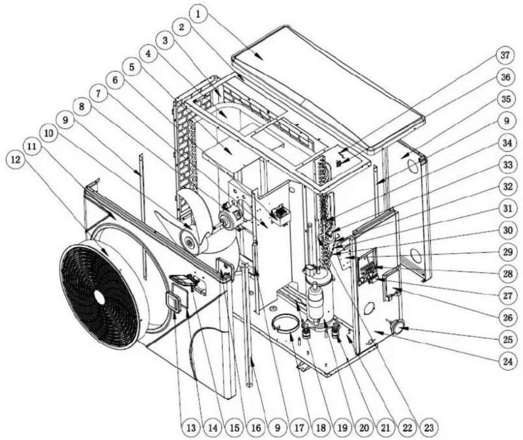
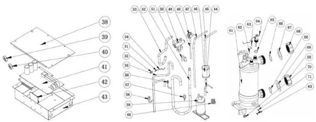
9. Exploded Diagram
9.8 Spare parts list: 74170
| NO | ERP | Spare parts | NO | ERP | Spare parts |
| 1 | 133260053 | Top cover | 37 | 117110020 | Ambient temp. sensor d3-TH1 |
| 2 | 108560058 | Top frame | 38 | 108540006 | Electric box cover |
| 3 | 108560078 | Left side panel | 39 | 117240002 | Magnet ring |
| 4 | 103000231 | Evaporator | 40 | 117240003 | Magnet ring |
| 5 | 108560062 | Fan motor bracket | 41 | 117100048 | PCB |
| 6 | 117230002 | Reactor | 42 | 117020239 | Modbus module |
| 7 | 108560061 | Isolation panel | 43 | 108560012 | Electric box |
| 8 | 112000031 | Fan motor | 44 | 113130021 | Pipe to dehydrator filter |
| 9 | 108560059 | Pillar | 45 | 113170032 | Dehydrator filter pipe |
| 10 | 132000023 | Fan blade | 46 | 120000066 | Filter |
| 11 | 133260050 | Front panel | 47 | 113120019 | Pipe from storage tank to EEV |
| 12 | 133020079 | Fan grill | 48 | 119000059 | EEV |
| 13 | 117020293 | Controller | 49 | 113080056 | EEV to distribution piping |
| 14 | 136010072 | Sealing ring | 50 | 121000034 | 4 way valve |
| 15 | 133020096 | Controller cover | 51 | 113060122 | Tube |
| 16 | 133020097 | Controller box | 52 | 113020518 | Gas return piping |
| 17 | 108110096 | Panel support | 53 | 113030108 | 4-way valve to exchanger |
| 18 | 142000077 | Compressor heating resistor | 54 | 117110021 | Discharge temp. sensor d6-TH3 |
| 19 | 142000144 | Evaporator heating resistor | 55 | 113010244 | Discharge pipe |
| 20 | 101000185 | Compressor | 56 | 120000097 | Gas valve |
| 21 | 101000185 | Compressor + damping feet | 57 | 112100046 | Low pressure switch |
| 22 | 108560066 | Base | 58 | 112100030 | High pressure switch |
| 23 | 103000231 | Evaporator pipe | 59 | 105000004 | Liquid storage tank |
| 24 | 133260051 | Right panel | 60 | 109000048 | Capillary |
| 25 | 106000011 | Pressure gauge | 61 | 102041062 | Titanium heat exchanger |
| 26 | 133250005 | Terminal blocks plastic cover | 62 | 117110011 | Water outlet temp. sensor d2-TH5 |
| 27 | 136010004 | Clip | 63 | 108010025 | Exchanger temperature sensor clip |
| 28 | 115000004 | 5-ways terminal block | 64 | 112100021-1 | Water flow switch |
| 29 | 108010065 | Terminal board | 65 | 136020083 | Sealing ring |
| 30 | 113190001 | Clip | 66 | 133020026 | Rubber ring on water connection |
| 31 | 113190007 | Sensor holder | 67 | 133020012 | Red rubber ring |
| 32 | 117110004 | Evaporator temperature sensor d5-TH2 | 68 | 113900082 | Water connection sets |
| 33 | 136020005 | Rubber block | 69 | 133020011 | Blue rubber ring |
| 34 | 103000231 | Distribution piping | 70 | 150000110 | Drainage plug |
| 35 | 133260052 | Back panel | 71 | 117110012 | Water inlet temp. sensor d1-TH6 |
| 36 | 133020010 | Ambient temp. sensor clip |
9. ExpbolebDiaggaann
9.9 Spare parts list: 74171
| NO | ERP | Spare parts | NO | ERP | Spare parts |
| 1 | 133260053 | Top cover | 37 | 117110020 | Ambient temp. sensor d3-TH1 |
| 2 | 108560058 | Top frame | 38 | 108540006 | Electric box cover |
| 3 | 108560078 | Left side panel | 39 | 117240002 | Magnet ring |
| 4 | 103000204 | Evaporator | 40 | 117240003 | Magnet ring |
| 5 | 108560062 | Fan motor bracket | 41 | 117100048 | PCB |
| 6 | 117230002 | Reactor | 42 | 117020239 | Modbus module |
| 7 | 108560061 | Isolation panel | 43 | 108560012 | Electric box |
| 8 | 112000031 | Fan motor | 44 | 113130021 | Pipe to dehydrator filter |
| 9 | 108560059 | Pillar | 45 | 113170032 | Dehydrator filter pipe |
| 10 | 132000023 | Fan blade | 46 | 120000066 | Filter |
| 11 | 133260050 | Front panel | 47 | 113120019 | Pipe from storage tank to EEV |
| 12 | 133020079 | Fan grill | 48 | 119000059 | EEV |
| 13 | 117020293 | Controller | 49 | 113080056 | EEV to distribution piping |
| 14 | 136010072 | Sealing ring | 50 | 121000028 | 4 way valve |
| 15 | 133020096 | Controller cover | 51 | 113060096 | Tube |
| 16 | 133020097 | Controller box | 52 | 113020387 | Gas return piping |
| 17 | 108110096 | Panel support | 53 | 113030093 | 4-way valve to exchanger |
| 18 | 142000077 | Compressor heating resistor | 54 | 117110021 | Discharge temp. sensor d6-TH3 |
| 19 | 142000144 | Evaporator heating resistor | 55 | 113010245 | Discharge pipe |
| 20 | 101000185 | Compressor | 56 | 120000097 | Gas valve |
| 21 | 101000185 | Compressor + damping feet | 57 | 112100046 | Low pressure switch |
| 22 | 108560066 | Base | 58 | 112100030 | High pressure switch |
| 23 | 103000204 | Evaporator pipe | 59 | 105000004 | Liquid storage tank |
| 24 | 133260051 | Right panel | 60 | 109000048 | Capillary |
| 25 | 106000011 | Pressure gauge | 61 | 102041064 | Titanium heat exchanger |
| 26 | 133250005 | Terminal blocks plastic cover | 62 | 117110011 | Water outlet temp. sensor d2-TH5 |
| 27 | 136010004 | Clip | 63 | 108010025 | Exchanger temperature sensor clip |
| 28 | 115000004 | 5-ways terminal block | 64 | 112100021-1 | Water flow switch |
| 29 | 108010065 | Terminal board | 65 | 136020083 | Sealing ring |
| 30 | 113190001 | Clip | 66 | 133020026 | Rubber ring on water connection |
| 31 | 113190007 | Sensor holder | 67 | 133020012 | Red rubber ring |
| 32 | 117110004 | Evaporator temperature sensor d5-TH2 | 68 | 113900082 | Water connection sets |
| 33 | 136020005 | Rubber block | 69 | 133020011 | Blue rubber ring |
| 34 | 103000204 | Distribution piping | 70 | 150000110 | Drainage plug |
| 35 | 133260052 | Back panel | 71 | 117110012 | Water inlet temp. sensor d1-TH6 |
| 36 | 133020010 | Ambient temp. sensor clip |
9. Exploded Diagram
9.10 Model: 74172, 74173, 74174, 74175
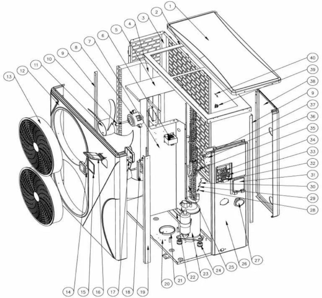
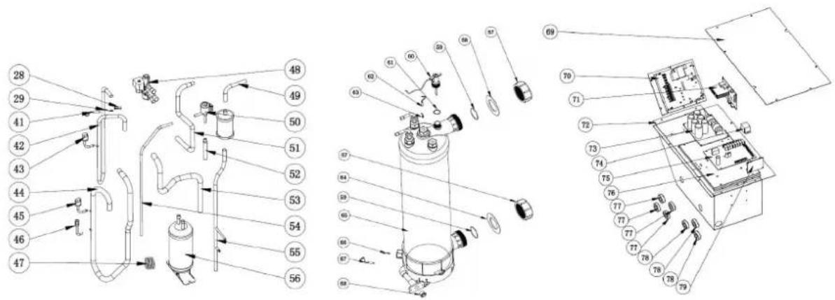
9. ExpboleckDiaggaann
9.11 Spare parts list: 74172
| NO | ERP | Spare parts | NO | ERP | Spare parts |
| 1 | 133250040 | Top cover | 41 | 117110021 | Discharge temp. sensor d6-TH3 |
| 2 | 108550027 | Top frame | 42 | 113010227 | Discharge pipe |
| 3 | 108550044 | Left side panel | 43 | 112100030 | High pressure switch |
| 4 | 103000208 | Evaporator | 44 | 113020326 | Gas return piping |
| 5 | 108550033 | Fan motor bracket | 45 | 112100046 | Low pressure switch |
| 6 | 117230001 | Reactor | 46 | 120000097 | Gas valve |
| 7 | 108120036 | Isolation panel | 47 | 109000043 | Capillary |
| 8 | 112000031 | Fan motor | 48 | 121000028 | 4 way valve |
| 9 | 108550028 | Pillar | 49 | 113170063 | Dehydrator filter pipe |
| 10 | 108010024 | Fan shaft cover | 50 | 119000061 | EEV |
| 11 | 132000015 | Fan blade | 51 | 113030191 | 4-way valve to exchanger |
| 12 | 133250037 | Front panel | 52 | 113080055 | EEV to distribution piping |
| 13 | 133020078 | Fan grill | 53 | 113060083 | Tube |
| 14 | 117020293 | Controller | 54 | 113120056 | Pipe from storage tank to EEV |
| 15 | 136010072 | Sealing ring | 55 | 113130043 | Pipe to dehydrator filter |
| 16 | 133020096 | Controller cover | 56 | 105000015 | Liquid storage tank |
| 17 | 133020097 | Controller box | 57 | 113900082 | Water connection sets |
| 18 | 108550009 | Panel support | 58 | 133020012 | Red rubber ring |
| 19 | 108550031 | Pillar | 59 | 133020026 | Rubber ring on water connection |
| 20 | 108550034 | Base tray | 60 | 112100021-1 | Water flow switch |
| 21 | 142000077 | Compressor heating resistor | 61 | 136020083 | Sealing ring |
| 22 | 142000079 | Evaporator heating resistor | 62 | 117110011 | Water outlet temp. sensor d2-TH5 |
| 23 | 101000185 | Compressor | 63 | 113190008 | Exchanger temperature sensor clip |
| 24 | 101000185 | Compressor damping feet | 64 | 133020011 | Blue rubber ring |
| 25 | 103000208 | Evaporator pipe | 65 | 102041063 | Titanium heat exchanger |
| 26 | 133250038 | Right panel | 66 | 108010025 | Exchanger temperature sensor clip |
| 27 | 106000011 | Pressure gauge | 67 | 117110012 | Water inlet temp. sensor d1-TH6 |
| 28 | 113190001 | Clip | 68 | 150000110 | Drainage plug |
| 29 | 113190007 | Sensor holder | 69 | 108120040 | Electric box cover |
| 30 | 117110004 | Evaporator temperature sensor d5-TH: | 70 | 117140016 | Driver board |
| 31 | 133250005 | Terminal blocks plastic cover | 71 | / | / |
| 32 | 136010004 | Clip | 72 | 108120038 | Electric box |
| 33 | 115000004 | 5-ways terminal block | 73 | 117260001 | Filter board |
| 34 | / | / | 74 | 142000038 | Relay |
| 35 | 136020005 | Rubber block | 75 | 117250007 | PCB |
| 36 | 108010065 | Terminal board | 76 | 108120039 | Scale board |
| 37 | 103000208 | Distribution piping | 77 | 117240002 | Magnet ring |
| 38 | 133250039 | Back panel | 78 | 117240003 | Magnet ring |
| 39 | 133020010 | Ambient temp. sensor clip | 79 | 117020239 | Modbus module |
| 40 | 117110020 | Ambient temp. sensor d3-TH1 |
9. Exploded Diagram
9.12 Spare parts list: 74173
| NO | ERP | Spare parts | NO | ERP | Spare parts |
| 1 | 133250040 | Top cover | 41 | 117110021 | Discharge temp. sensor d6-TH3 |
| 2 | 108550027 | Top frame | 42 | 113010228 | Discharge pipe |
| 3 | 108550044 | Left side panel | 43 | 112100030 | High pressure switch |
| 4 | 103000209 | Evaporator | 44 | 113020326 | Gas return piping |
| 5 | 108550030 | Fan motor bracket | 45 | 112100046 | Low pressure switch |
| 6 | 117230001 | Reactor | 46 | 120000097 | Gas valve |
| 7 | 108120036 | Isolation panel | 47 | 109000043 | Capillary |
| 8 | 112000031 | Fan motor | 48 | 121000028 | 4 way valve |
| 9 | 108550028 | Pillar | 49 | 113170064 | Dehydrator filter pipe |
| 10 | 108010024 | Fan shaft cover | 50 | 119000062 | EEV |
| 11 | 132000015 | Fan blade | 51 | 113030191 | 4-way valve to exchanger |
| 12 | 133250037 | Front panel | 52 | 113080055 | EEV to distribution piping |
| 13 | 133020078 | Fan grill | 53 | 113060083 | Tube |
| 14 | 117020293 | Controller | 54 | 113120056 | Pipe from storage tank to EEV |
| 15 | 136010072 | Sealing ring | 55 | 113130043 | Pipe to dehydrator filter |
| 16 | 133020096 | Controller cover | 56 | 105000015 | Liquid storage tank |
| 17 | 133020097 | Controller box | 57 | 113900082 | Water connection sets |
| 18 | 108550009 | Panel support | 58 | 133020012 | Red rubber ring |
| 19 | 108550031 | Pillar | 59 | 133020026 | Rubber ring on water connection |
| 20 | 108550034 | Base tray | 60 | 112100021-1 | Water flow switch |
| 21 | 142000077 | Compressor heating resistor | 61 | 136020083 | Sealing ring |
| 22 | 142000079 | Evaporator heating resistor | 62 | 117110011 | Water outlet temp. sensor d2-TH5 |
| 23 | 101000186 | Compressor | 63 | 113190008 | Exchanger temperature sensor clip |
| 24 | 101000186 | Compressor damping feet | 64 | 133020011 | Blue rubber ring |
| 25 | 103000209 | Evaporator pipe | 65 | 102041067 | Titanium heat exchanger |
| 26 | 133250038 | Right panel | 66 | 108010025 | Exchanger temperature sensor clip |
| 27 | 106000011 | Pressure gauge | 67 | 117110012 | Water inlet temp. sensor d1-TH6 |
| 28 | 113190001 | Clip | 68 | 150000110 | Drainage plug |
| 29 | 113190007 | Sensor holder | 69 | 108120040 | Electric box cover |
| 30 | 117110004 | Evaporator temperature sensor d5-TH: | 70 | 117140016 | Driver board |
| 31 | 133250005 | Terminal blocks plastic cover | 71 | / | / |
| 32 | 136010004 | Clip | 72 | 108120038 | Electric box |
| 33 | 115000004 | 5-ways terminal block | 73 | 117260001 | Filter board |
| 34 | / | / | 74 | 142000038 | Relay |
| 35 | 136020005 | Rubber block | 75 | 117250007 | PCB |
| 36 | 108010065 | Terminal board | 76 | 108120039 | Scale board |
| 37 | 103000209 | Distribution piping | 77 | 117240002 | Magnet ring |
| 38 | 133250039 | Back panel | 78 | 117240003 | Magnet ring |
| 39 | 133020010 | Ambient temp. sensor clip | 79 | 117020239 | Modbus module |
| 40 | 117110020 | Ambient temp. sensor d3-TH1 |
9. ExptobekDlāggaam
9.13 Spare parts list: 74174
| NO | ERP | Spare parts | NO | ERP | Spare parts |
| 1 | 133250040 | Top cover | 41 | 117110021 | Discharge temp. sensor d6-TH3 |
| 2 | 108550027 | Top frame | 42 | 113010158 | Discharge pipe |
| 3 | 108550044 | Left side panel | 43 | 112100030 | High pressure switch |
| 4 | 103000208 | Evaporator | 44 | 113020427 | Gas return piping |
| 5 | 108550033 | Fan motor bracket | 45 | 112100046 | Low pressure switch |
| 6 | 117230001 | Reactor | 46 | 120000023 | Gas valve |
| 7 | 108120036 | Isolation panel | 47 | 109000043 | Capillary |
| 8 | 112000031 | Fan motor | 48 | 121000028 | 4 way valve |
| 9 | 108550028 | Pillar | 49 | 113170063 | Dehydrator filter pipe |
| 10 | 108010024 | Fan shaft cover | 50 | 119000061 | EEV |
| 11 | 132000015 | Fan blade | 51 | 113030191 | 4-way valve to exchanger |
| 12 | 133250037 | Front panel | 52 | 113080055 | EEV to distribution piping |
| 13 | 133020078 | Fan grill | 53 | 113060083 | Tube |
| 14 | 117020293 | Controller | 54 | 113120056 | Pipe from storage tank to EEV |
| 15 | 136010072 | Sealing ring | 55 | 113130043 | Pipe to dehydrator filter |
| 16 | 133020096 | Controller cover | 56 | 105000015 | Liquid storage tank |
| 17 | 133020097 | Controller box | 57 | 113900082 | Water connection sets |
| 18 | 108550009 | Panel support | 58 | 133020012 | Red rubber ring |
| 19 | 108550031 | Pillar | 59 | 133020026 | Rubber ring on water connection |
| 20 | 108550034 | Base tray | 60 | 112100021-1 | Water flow switch |
| 21 | 142000077 | Compressor heating resistor | 61 | 136020083 | Sealing ring |
| 22 | 142000079 | Evaporator heating resistor | 62 | 117110011 | Water outlet temp. sensor d2-TH5 |
| 23 | 101000149 | Compressor | 63 | 113190008 | Exchanger temperature sensor clip |
| 24 | 101000149 | Compressor damping feet | 64 | 133020011 | Blue rubber ring |
| 25 | 103000208 | Evaporator pipe | 65 | 102041019 | Titanium heat exchanger |
| 26 | 133250038 | Right panel | 66 | 108010025 | Exchanger temperature sensor clip |
| 27 | 106000011 | Pressure gauge | 67 | 117110012 | Water inlet temp. sensor d1-TH6 |
| 28 | 113190001 | Clip | 68 | 150000110 | Drainage plug |
| 29 | 113190007 | Sensor holder | 69 | 108120040 | Electric box cover |
| 30 | 117110004 | Evaporator temperature sensor d5-TH: | 70 | 117140019 | Driver board |
| 31 | 133250005 | Terminal blocks plastic cover | 71 | 117140006 | Fan motor driver board |
| 32 | 136010004 | Clip | 72 | 108120038 | Electric box |
| 33 | 115000006 | 5-ways terminal for electricity | 73 | 117260002 | Filter board |
| 34 | 115000027 | 3-ways terminal for filtration pump | 74 | 142000038 | Relay |
| 35 | 136020005 | Rubber block | 75 | 117250008 | PCB |
| 36 | 108010065 | Terminal board | 76 | 108120039 | Scale board |
| 37 | 103000208 | Distribution piping | 77 | 117240002 | Magnet ring |
| 38 | 133250039 | Back panel | 78 | 117240003 | Magnet ring |
| 39 | 133020010 | Ambient temp. sensor clip | 79 | 117020239 | Modbus module |
| 40 | 117110020 | Ambient temp. sensor d3-TH1 |
9. Exploded Diagram
9.14 Spare parts list: 74175
| NO | ERP | Spare parts | NO | ERP | Spare parts |
| 1 | 133250040 | Top cover | 41 | 117110021 | Discharge temp. sensor d6-TH3 |
| 2 | 108550027 | Top frame | 42 | 113010158 | Discharge pipe |
| 3 | 108550044 | Left side panel | 43 | 112100030 | High pressure switch |
| 4 | 103000209 | Evaporator | 44 | 113020427 | Gas return piping |
| 5 | 108550030 | Fan motor bracket | 45 | 112100046 | Low pressure switch |
| 6 | 117230001 | Reactor | 46 | 120000023 | Gas valve |
| 7 | 108120036 | Isolation panel | 47 | 109000043 | Capillary |
| 8 | 112000031 | Fan motor | 48 | 121000028 | 4 way valve |
| 9 | 108550028 | Pillar | 49 | 113170064 | Dehydrator filter pipe |
| 10 | 108010024 | Fan shaft cover | 50 | 119000061 | EEV |
| 11 | 132000015 | Fan blade | 51 | 113030191 | 4-way valve to exchanger |
| 12 | 133250037 | Front panel | 52 | 113080055 | EEV to distribution piping |
| 13 | 133020078 | Fan grill | 53 | 113060083 | Tube |
| 14 | 117020293 | Controller | 54 | 113120056 | Pipe from storage tank to EEV |
| 15 | 136010072 | Sealing ring | 55 | 113130043 | Pipe to dehydrator filter |
| 16 | 133020096 | Controller cover | 56 | 105000015 | Liquid storage tank |
| 17 | 133020097 | Controller box | 57 | 113900082 | Water connection sets |
| 18 | 108550009 | Panel support | 58 | 133020012 | Red rubber ring |
| 19 | 108550031 | Pillar | 59 | 133020026 | Rubber ring on water connection |
| 20 | 108550036 | Base tray | 60 | 112100021-1 | Water flow switch |
| 21 | 142000077 | Compressor heating resistor | 61 | 136020083 | Sealing ring |
| 22 | 142000079 | Evaporator heating resistor | 62 | 117110011 | Water outlet temp. sensor d2-TH5 |
| 23 | 101000149 | Compressor | 63 | 113190008 | Exchanger temperature sensor clip |
| 24 | 101000149 | Compressor damping feet | 64 | 133020011 | Blue rubber ring |
| 25 | 103000209 | Evaporator pipe | 65 | 102041066 | Titanium heat exchanger |
| 26 | 133250038 | Right panel | 66 | 108010025 | Exchanger temperature sensor clip |
| 27 | 106000011 | Pressure gauge | 67 | 117110012 | Water inlet temp. sensor d1-TH6 |
| 28 | 113190001 | Clip | 68 | 150000110 | Drainage plug |
| 29 | 113190007 | Sensor holder | 69 | 108120040 | Electric box cover |
| 30 | 117110004 | Evaporator temperature sensor d5-TH: | 70 | 117140019 | Driver board |
| 31 | 133250005 | Terminal blocks plastic cover | 71 | 117140006 | Fan motor driver board |
| 32 | 136010004 | Clip | 72 | 108120038 | Electric box |
| 33 | 115000006 | 5-ways terminal for electricity | 73 | 117260002 | Filter board |
| 34 | 115000027 | 3-ways terminal for filtration pump | 74 | 142000038 | Relay |
| 35 | 136020005 | Rubber block | 75 | 117250008 | PCB |
| 36 | 108010065 | Terminal board | 76 | 108120039 | Scale board |
| 37 | 103000209 | Distribution piping | 77 | 117240002 | Magnet ring |
| 38 | 133250039 | Back panel | 78 | 117240003 | Magnet ring |
| 39 | 133020010 | Ambient temp. sensor clip | 79 | 117020239 | Modbus module |
| 40 | 117110020 | Ambient temp. sensor d3-TH1 |
10. Maintéancee
10. Maintenance
Warning!
-Before any maintenance work on the appliance, you must cut the electricity supply as there is a electric shock which may cause material damage, serious injury or even death.
- It is recommended that the appliance undergo general servicing at least on a yearly basis to en proper operation, maintain performance levels and prevent any possible failures. These operations are carried out at the user's expense, by a qualified technician.
for maintenance to be carried out by a qualified technician.
-For maintenance to be carried out by a qualified technician, please read the safety instructions in pages provided in the chapters of maintenance before performing any of the maintenance operation described below.
(1) You should check the water supply system regularly to avoid air entering the system and creation of low water flow, because it would reduce the performance and reliability of HP unit.
(2) Clean your pools and filtration system regularly to avoid the damage of the unit.
(3) Only a qualified technician is authorized to operate the cooling system pressure. You should drain the water from the heat pump if it will stop running for a long time (especially during the winter season or when the ambient temperature drops below 0^ C).
(4) Check the water levels before the unit start after a long break in usage.
(5) When the unit is running, there will be condensate water discharging from the bottom of the unit. This is normal.
(6) Action of filling gas must be conducted by professional with R32 operating license.
1.1 Description Description
Modes: 74172/74173/74174/74175
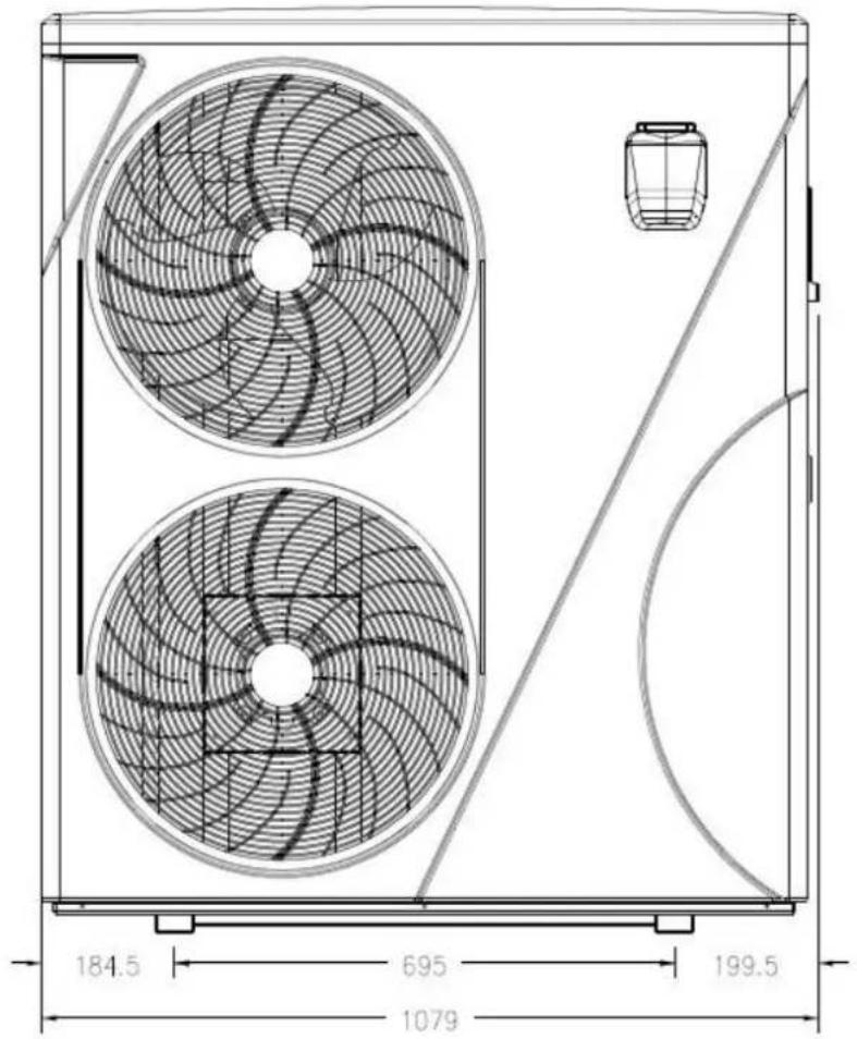
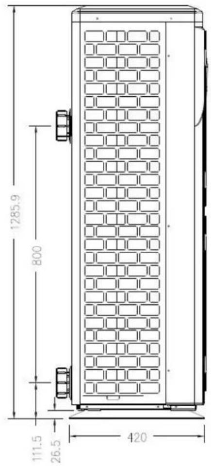
2. Condition de transport
natural_image
Illustration of a brown cardboard box with a blue pallet jack and yellow base (no text or symbols)natural_image
Close-up of a black conical object with a metallic bolt and hexagonal nut, placed on a wooden surface (no text or symbols visible)Patin caoutchouc anti-vibration, qté 4
natural_image
Black cable with a small red mark on the left side, isolated on white background (no text or symbols)Modbus fil de raccordement
natural_image
White powder bag wrapped in plastic wrap, no visible text or symbolsnatural_image
Two white plastic pipe fittings, one cylindrical and one threaded, shown against a neutral background (no text or symbols visible)natural_image
3D rendering of a white and red pipe fitting with flanges (no text or symbols)4. Accessoires et options
line
| Logic of auto mode | Tset=28°C | |---|---| | Heating | 26°C | | Standby | 27°C | | Heating | 29°C | | Standby | 30°C | | Cooling | 28°C | | Standby | 27°C | | Heating | 29°C |line
| Condition | Temperature (°C) | |---|---| | Compressor Stop and EE04 displays | 7 | | Frequency Decrease | 5 | | Normal Operation | 5 |line
| Condition | Temperature (°C) | |---|---| | Normal Operation | 0 | | Compressor Stop and PP11 displays | -7 | | Frequency Decrease | -5 |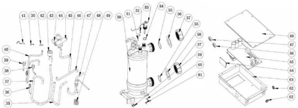
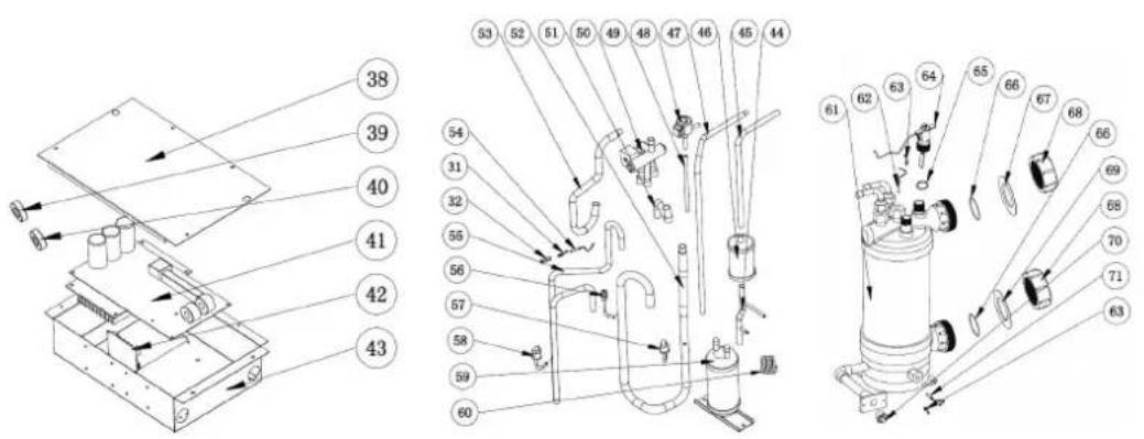
9. Schéma éclaté
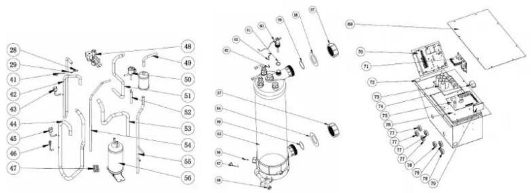
9. Schéma éclaté
natural_image
Illustration of a brown cardboard box with a blue pallet jack beside it, no text or symbols present.natural_image
Close-up of a black conical object with a metallic bolt and hexagonal end (no visible text or symbols)natural_image
Coiled black cable or wire with a small red mark at the top (no text or symbols visible)natural_image
White rectangular container filled with white powder, no visible text or symbolsWinter Cover, 1 st
natural_image
Coiled white plastic hose or coiled tube, no text or symbols visibleWater drainagebuizen, 2 pcs
natural_image
Close-up of a black conical object with a metallic bolt and nut, placed on a wooden surface (no text or symbols visible)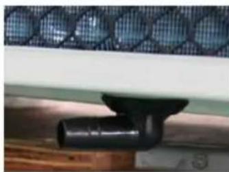
natural_image
Close-up of a black pipe fitting attached to a wooden surface, with a mesh fence in the background (no text or symbols visible)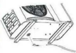
natural_image
Technical line drawing of a mechanical assembly with no visible text or symbols
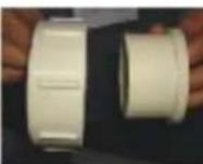

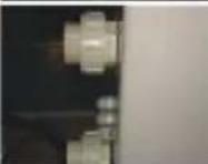
Anti-vibratie rubbers
OPMERKING:
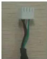
natural_image
Close-up of a black cable with green wires against a wooden background (no text or symbols visible)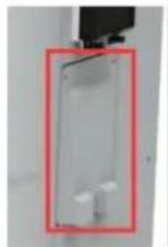
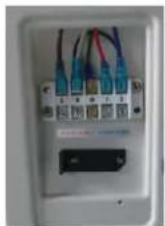
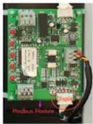
natural_image
Close-up of a green printed circuit board with visible components and wiring (no readable text or symbols)line
| Logic of auto mode | Tset=28°C | |---|---| | Heating | 26°C | | Standby | 27°C | | Heating | 29°C | | Standby | 30°C | | Cooling | 28°C | | Heating | 27°C | | Heating | 29°C |7.2.3


van P1 tot P1
Tset- 0.5 = 28-0.5=27.5°C
Tset+ 0.5 = 28+0.5=28.5°C
line
| Condition | Temperature (°C) | |---|---| | Compressor Stop and EE04 displays | 7 | | Frequency Decrease | 5 | | Normal Operation | 5 |line
| Condition | Temperature (°C) | |---|---| | Normal Operation | 0 | | Compressor Stop and PP11 displays | -7 | | Frequency Decrease | -5 |For example as below:

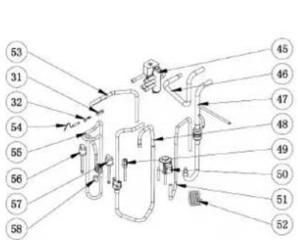

9. Open geklapt diagram

9. Open geklapt diagram

9. Open geklapt diagram

9. Open geklapt diagram
natural_image
Illustration of a brown cardboard box with a blue handle and yellow pallet jack (no text or symbols)natural_image
3D rendering of a white and red pipe fitting with two flanges (no text or symbols visible)
NOTA
natural_image
Close-up of a white electrical terminal panel with multiple colored wires and a black connector (no visible text or symbols)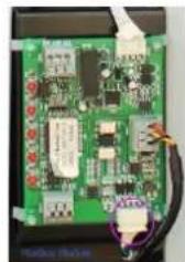
natural_image
Close-up of a green printed circuit board with visible components and wiring (no readable text or symbols)natural_image
Interior view of an electrical enclosure showing wiring and components (no visible text or symbols)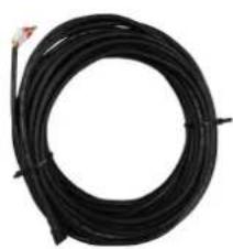
natural_image
Coiled black cable or wire with a small red connector at the top (no text or symbols visible)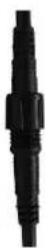
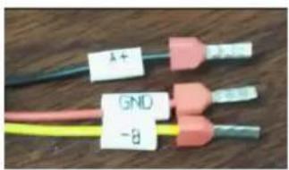
line
| Logic of auto mode | Tset=28°C | |---|---| | Heating | 26°C | | Standby | 29°C | | Heating | 27°C | | Standby | 29°C | | Cooling | 30°C | | Standby | 28°C | | Heating | 27°C | | Heating | 29°C |7.2.4 Botón


line
| Condition | Temperature (°C) | |---|---| | Compressor Stop and EE04 displays | 7 | | Frequency Decrease | 5 | | Normal Operation | 5 |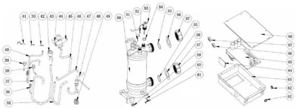

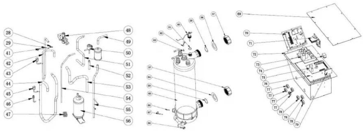
natural_image
Technical line drawing of a fan assembly with dimension annotations (706 and 16.5), no readable text or symbols beyond measurement lines.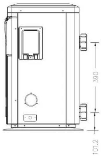
natural_image
Technical line drawing of a mechanical device with dimension annotations (390 and 101.2) and no readable text or symbols.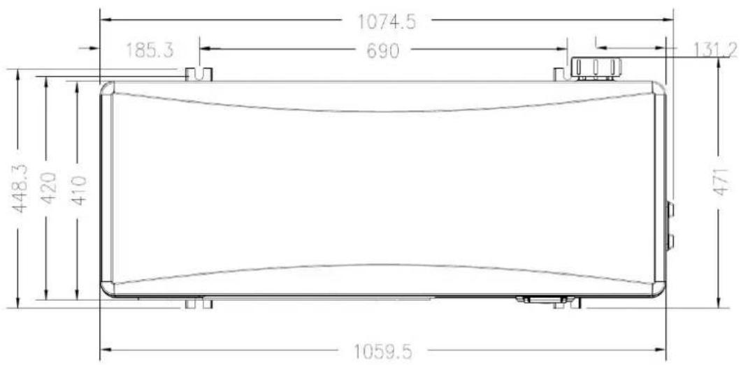
1.Beschreibung
Modelle:74170/74171
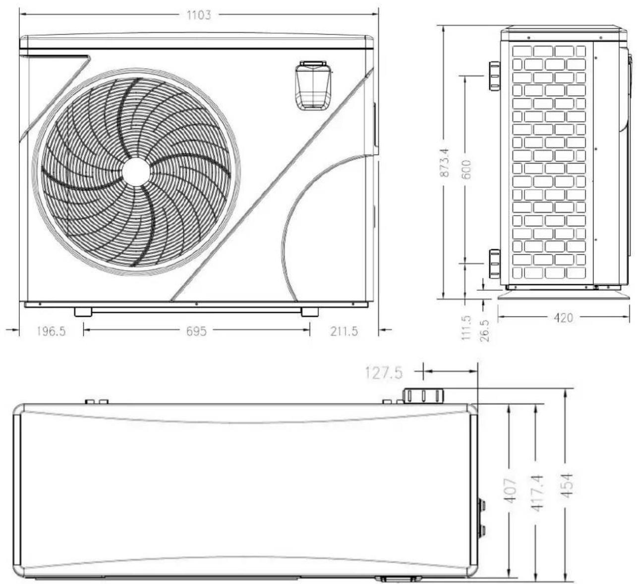
1. Beschreibung
Modelle: 74172/74173/74174/74175
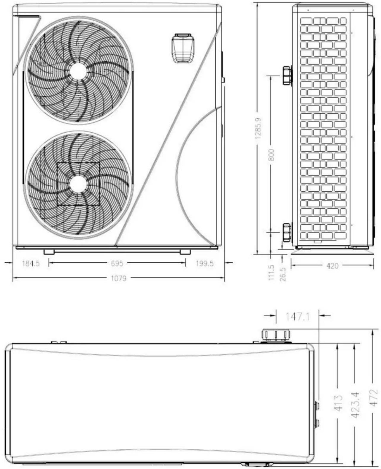
2. Transportinformationen
natural_image
Illustration of a brown cardboard box with a blue pallet jack beside it, no text or symbols present.natural_image
Close-up of a black conical object with a metallic bolt and hexagonal nut, resting on a wooden surface (no text or symbols visible)natural_image
Packaged white substance with transparent plastic wrap (no visible text or symbols)Winter-Abdeckung, 1 stk
Modbus-Signaldraht, 1 Stk
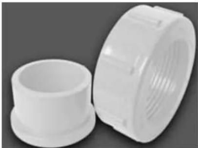
natural_image
Two white plastic pipe fittings, one closed and one threaded (no text or symbols visible)natural_image
3D rendering of a white and red pipe fitting with flanges (no text or symbols visible)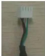
natural_image
Close-up of a black cable with green and brown wires attached to a white connector (no text or symbols visible)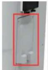
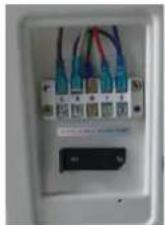
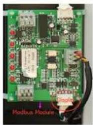
line
| Logic of auto mode | Tset=28°C | |---|---| | Heating | 26°C | | Standby | 29°C | | Cooling | 28°C | | Standby | 27°C | | Heating | 28°C | | Heating | 27°C |überprüfen
7. Start-up of the Heat Pump
| Code mit Verbinden | Parameter P | Beschreibung |
| 74166 | 21b6 | PAC PROELYO TOUCHET-08 |
| 74167 | 21b7 | PAC PROELYO TOUCHET-10 |
| 74168 | 21b8 | PAC PROELYO TOUCHET-13 |
| 74169 | 21b9 | PAC PROELYO TOUCHET-15 |
| 74170 | 21ba | PAC PROELYO TOUCHET-19 |
| 74171 | 21bb | PAC PROELYO TOUCHET-25 |
| 74172 | 21bc | PAC PROELYO TOUCHET-30 |
| 74173 | 21bd | PAC PROELYO TOUCHET-35 |
| 74174 | 21be | PAC PROELYO TOUCHET-30T |
| 74175 | 21bf | PAC PROELYO TOUCHET-35T |
Tset = Tsetting Wassertemperatur
Tset-0.5 = less 0.5^ C than Tsetting temperatur; Tset-0.5 = 28-0.5=27.5°C
Tset+0.5= more 0.5°C than Tsetting temperatur; Tset+ 0.5 = 28+0.5=28.5°C
line
| Condition | Temperature (°C) | |---|---| | Compressor Stop and EE04 displays | - | | Frequency Decrease | - | | Normal Operation | - | | T_SET Temp. +5°C | - | | T_SET Temp. +7°C | - | | T water out (°C) | - |line
| Condition | Temperature (°C) | |---|---| | Normal Operation | 0 | | Frequency Decrease | -5 | | Compressor Stop and PP11 displays | -7 |
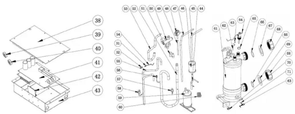
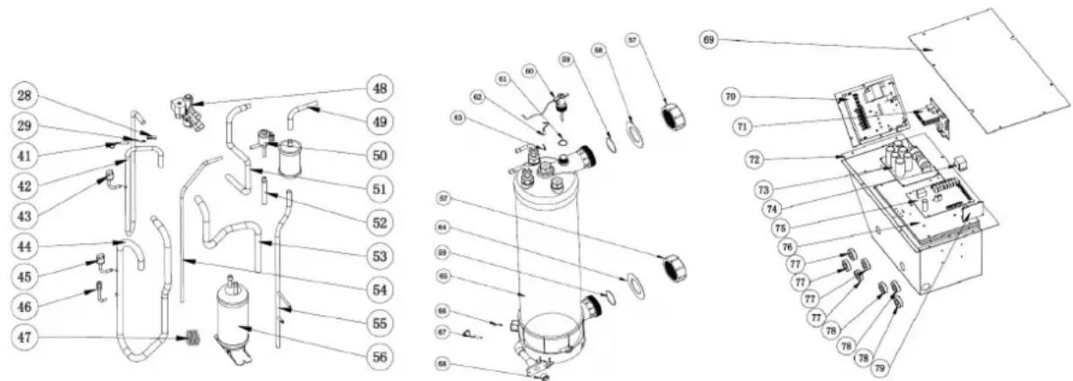
natural_image
Illustration of a brown cardboard box next to a yellow pallet jack (no text or symbols)natural_image
3D rendering of a white PVC pipe fitting with red valve ports, no text or symbols visiblenatural_image
Close-up of a black conical object with a metallic bolt and hexagonal nut, placed on a wooden surface (no text or symbols visible)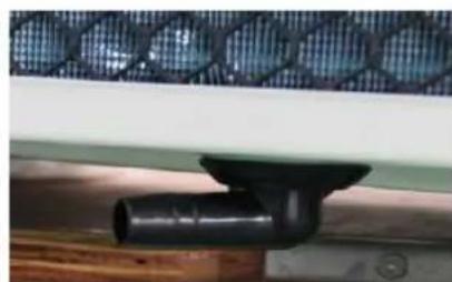
natural_image
Close-up of a black pipe fitting attached to a wooden surface, with a mesh fence in the background (no text or symbols visible)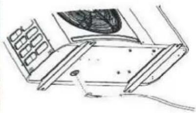
natural_image
Technical line drawing of a mechanical assembly with no visible text or symbols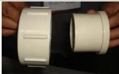
natural_image
Close-up of hands holding a white plastic pipe fitting (no text or symbols visible)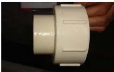
natural_image
Close-up of a white plastic pipe fitting with side grooves (no text or symbols visible)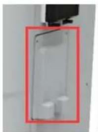
natural_image
Close-up of a transparent plastic enclosure with two white components, enclosed in a red-bordered frame (no text or symbols visible)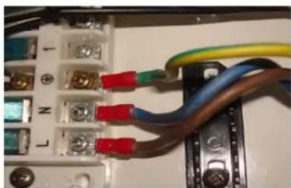
natural_image
Electrical wiring diagram showing connections between components including capacitors, resistors, and wires (no text or symbols visible)
natural_image
Close-up of a transparent plastic enclosure with two white cylindrical components, enclosed in a red-bordered frame (no text or symbols visible)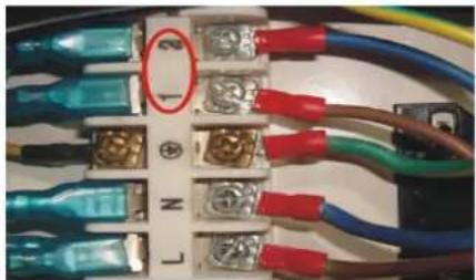
natural_image
Close-up of electrical wiring with various colored connectors and terminal blocks (no visible text or symbols)5. Location and connection
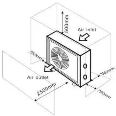
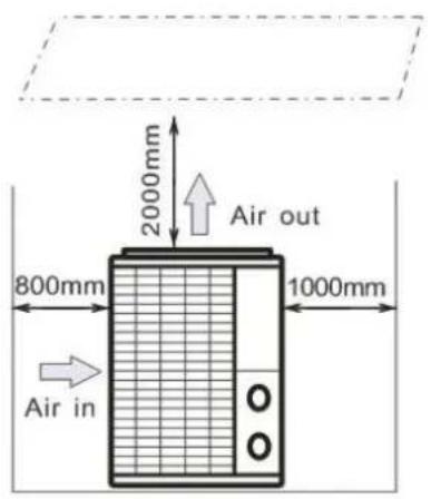
5. Location and connection

natural_image
Close-up of a black cable with green and white wires, no visible text or symbols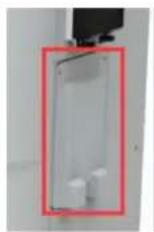

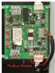
line
| Logic of auto mode | Tset=28°C | |---|---| | Heating | 26°C | | Standby | 27°C | | Heating | 29°C | | Standby | 30°C | | Cooling | 28°C | | Standby | 27°C | | Heating | 29°C |line
| Condition | Temperature (°C) | |---|---| | Compressor Stop and EE04 displays | 7 | | Frequency Decrease | 5 | | Normal Operation | 5 |line
| Condition | Temperature (°C) | |---|---| | Normal Operation | 0 | | Compressor Stop and PP11 displays | -7 | | Frequency Decrease | -5 |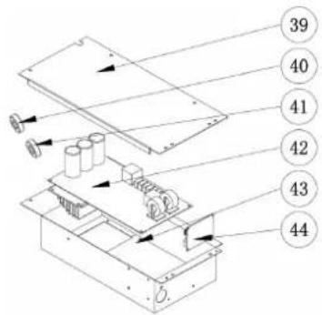
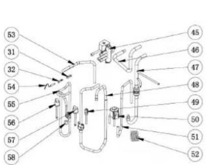
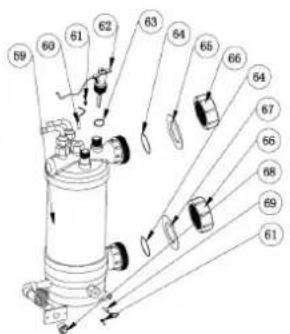


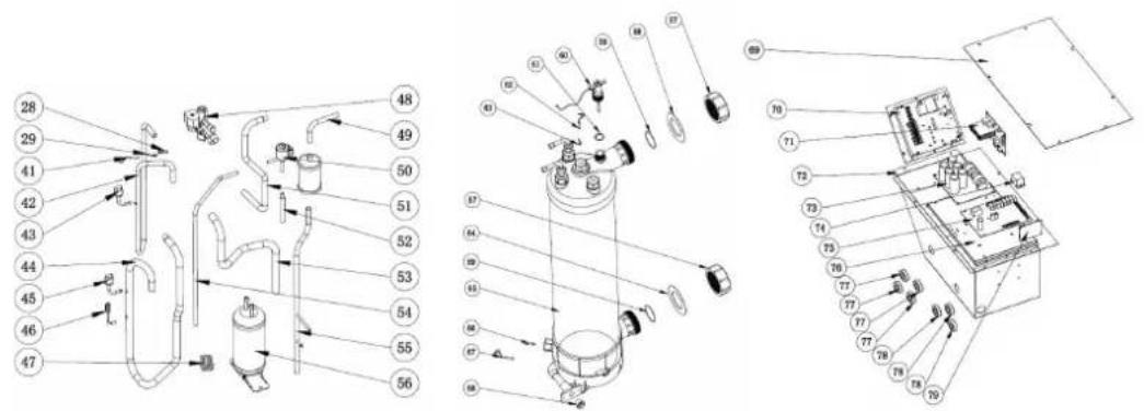
natural_image
Illustration of a brown cardboard box with a blue pallet jack beside it, no text or symbols present.natural_image
Close-up of a black conical object with a metallic bolt and hexagonal nut, resting on a wooden surface (no text or symbols visible)natural_image
White plastic bag wrapped in plastic wrap, no visible text or symbolsCapa de inverno, 1 pc
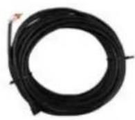
Fio de sinal Modbus, 1 pc

natural_image
Two white plastic pipe fittings, one cylindrical and one threaded, shown against a neutral background (no text or symbols visible)natural_image
3D rendering of a white and red pipe fitting with flanges (no text or symbols visible)4. Acessórios
4.3 Accessories Installation
6. Cablagtem eléctrica
6. Cablagtem eléctrica
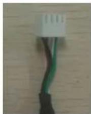
natural_image
Close-up of a black and green cable with a white connector at the top (no text or symbols visible)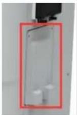
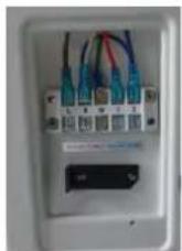
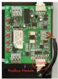
7. Arranque da bomba de calor
line
| Logic of auto mode | Tset=28°C | |---|---| | Heating | 26°C | | Standby | 27°C | | Heating | 29°C | | Standby | 30°C | | Cooling | 28°C | | Standby | 27°C | | Heating | 29°C | | Heating | 28°C |7. Arranque da bomba de calor
piscará.
Tset-0.5 = less 0.5°C than Tsetting temperatura, Tset-0.5 = 28-0.5=27.5°C
Tset+0.5= more 0.5°C than Tsetting temperatura, Tset+0.5 = 28+0.5=28.5°C
7. Arranque da bomba de calor
line
| Condition | Temperature (°C) | |---|---| | Compressor Stop and EE04 displays | - | | Frequency Decrease | - | | Normal Operation | - | | T_SET Temp. +5°C | - | | T_SET Temp. +7°C | - |line
| Condition | Temperature (°C) | |---|---| | Normal Operation | 0 | | Frequency Decrease | -5 | | Compressor Stop and PP11 displays | -7 |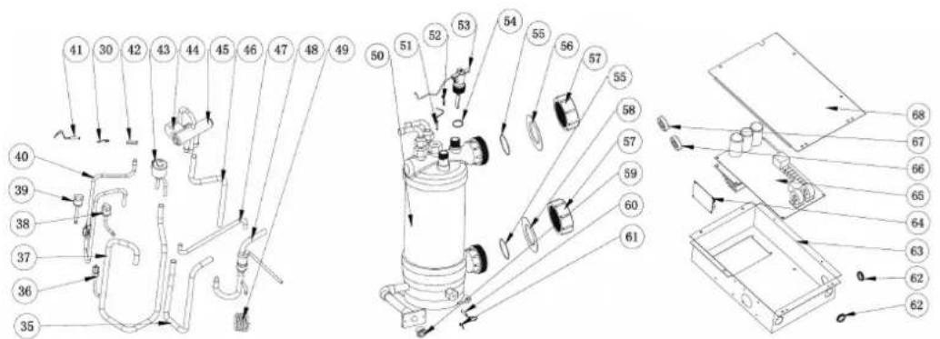

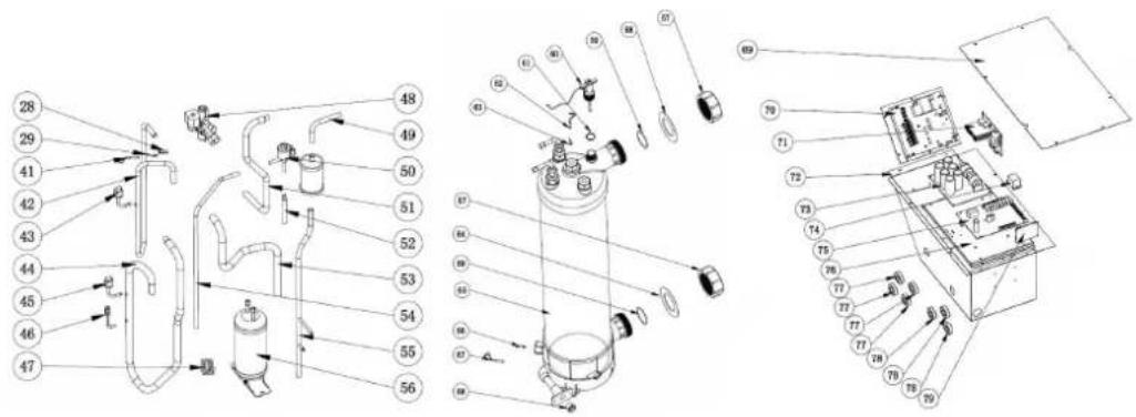
natural_image
Illustration of a brown cardboard box with a blue pallet jack beside it, no text or symbols present.natural_image
Close-up of a black conical object with a metallic bolt and nut, resting on a wooden surface (no text or symbols visible)natural_image
White plastic bag wrapped in plastic wrap, no visible text or symbolsnatural_image
Coiled black cable or wire against white background (no text or symbols visible)natural_image
Two white plastic pipe fittings, one cylindrical and one threaded, shown against a neutral background (no text or symbols visible)natural_image
3D rendering of a white and red pipe fitting with two flanges (no text or symbols visible)natural_image
Close-up of a black conical object with a metallic bolt and hexagonal nut, placed on a wooden surface (no text or symbols visible)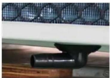
natural_image
Close-up of a black pipe fitting attached to a wooden surface, with a mesh-patterned metal panel above (no text or symbols visible)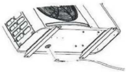
natural_image
Technical line drawing of a mechanical assembly with no visible text or symbols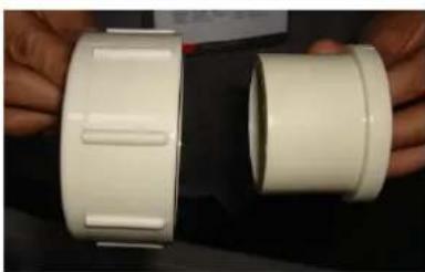
natural_image
Two white plastic pipe fittings held by hands, no visible text or symbols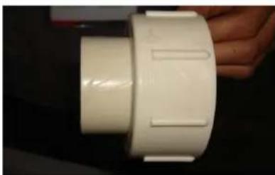
natural_image
Close-up of a white plastic pipe fitting with side grooves, held by hand (no text or symbols visible)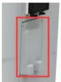
natural_image
Close-up of a white plastic enclosure with a red rectangular frame, no visible text or symbols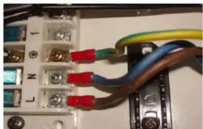
natural_image
Electrical wiring and components with colored wires (no visible text or symbols)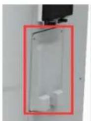
natural_image
Close-up of a transparent cylindrical device with two small white components, enclosed in a red-bordered frame (no text or symbols visible)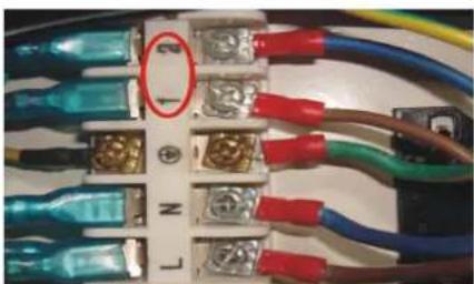
natural_image
Close-up of an electrical terminal block with multiple colored wires and connectors (no visible text or symbols)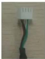
natural_image
Close-up of a black cable with green and red wires attached to a white connector (no text or symbols visible)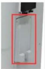


natural_image
Close-up of a green printed circuit board with electronic components and wiring (no readable text or symbols)Water pump
line
| Logic of auto mode | Tset=28°C | |---|---| | Heating | 26°C | | Standby | 27°C | | Standby | 29°C | | Heating | 30°C | | Standby | 28°C | | Cooling | 28°C | | Heating | 27°C | | Heating | 29°C |line
| Condition | Temperature (°C) | |---|---| | Compressor Stop and EE04 displays | 7 | | Frequency Decrease | 5 | | Normal Operation | 5 |line
| Condition | Temperature (°C) | |---|---| | Normal Operation | 0 | | Compressor Stop and PP11 displays | -7 | | Frequency Decrease | -5 |


2. Transport information
natural_image
Illustration of a brown cardboard box with a blue pallet jack beside it (no text or symbols)natural_image
3D rendering of a white and red pipe fitting with flanges (no text or symbols)6.2 Ref: 74172/74173
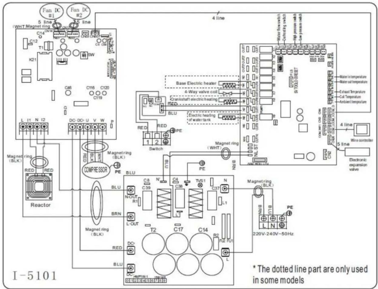
natural_image
Close-up of a black cable with green wires and a white connector (no text or symbols visible)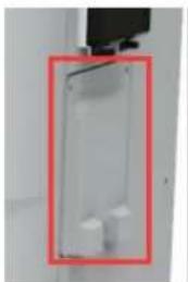
natural_image
Close-up of a transparent mechanical device with a red rectangular frame and two small white components, mounted on a white cabinet (no visible text or symbols)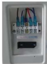
natural_image
Close-up of a white electronic device with multiple connected ports and cables (no visible text or symbols)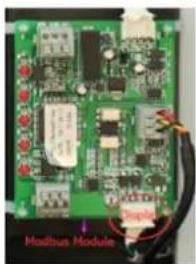
6.7 Installation of the Modbus/Fluidra Connect Signal Wire
Foto(6) Foto(7) Foto(8) Foto(9)
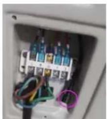
natural_image
Interior view of an electrical enclosure showing wiring and components (no visible text or symbols)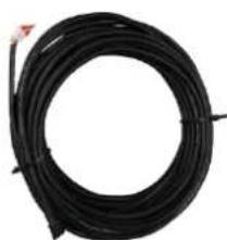
natural_image
Coiled black cable or wire with a small red mark at the top (no text or symbols visible)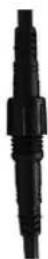
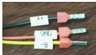
line
| Logic of auto mode | Tset=28°C | |---|---| | Heating | 26°C | | Standby | 27°C | | Heating | 29°C | | Standby | 30°C | | Cooling | 28°C | | Standby | 27°C | | Heating | 29°C |7.4 Cooling operation logic
line
| Condition | Temperature (°C) | |---|---| | Compressor Stop and EE04 displays | T_SET Temp. +7°C | | Frequency Decrease | T_SET Temp. +5°C | | Normal Operation | T_SET Temp. +5°C |line
| Condition | Temperature (°C) | |---|---| | Normal Operation | -5 | | Frequency Decrease | -5 | | Compressor Stop and PP11 displays | -7 |
9. Exploderat diagram
9.4 Reservdelar: 74167
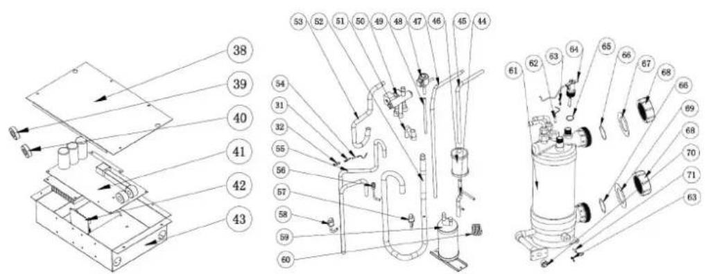
9. Exploderat diagram
9.8 Reservdelar: 74170

9. Exploderat diagram
1.1 In accordance with these provisions, the seller guarantees that the product corresponding to this guarantee (“the Product”) is in perfect condition at the time of delivery.
1.2 The Guarantee Term for the Product is two (2) years from the time it is delivered to the purchaser.
1.3 In the event of any defect in the Product that is notified by the purchaser to the seller during the Guarantee Term, the seller will be obliged to repair or replace the Product, at his own cost and wherever he deems suitable, unless this is impossible or unreasonable.
1.4 If it is not possible to repair or replace the Product, the purchaser may ask for a proportional reduction in the price or, if the defect is sufficiently significant, the termination of the sales contract.
1.5 The replaced or repaired parts under this guarantee, will not extend the guarantee period of the original Product, but will have a separate guarantee.
1.6 In order for this guarantee to come into effect, the purchaser must provide proof of the date of purchase and delivery of the Product.
1.7 If, after six months from the delivery of the Product to the purchaser, he notifies a defect in the Product, the purchaser must provide proof of the origin and existence of the alleged defect.
1.8 This Guarantee Certificate is issued without prejudice to the rights corresponding to consumers under national regulations.
2 INDIVIDUAL TERMS
2.1 This guarantee covers the products referred to in this manual.
2.2 This Guarantee Certificate will only be applicable in European Union countries.
2.3 For this guarantee to be effective, the purchaser must strictly follow the Manufacturer's instructions included in the documentation provided with the Product, in cases where it is applicable according to the range and model of the Product.
2.4 When a time schedule is specified for the replacement, maintenance or cleaning of certain parts or components of the Product, the guarantee will only be valid if this time schedule has been followed.
3 LIMITATIONS
3.1 This guarantee will only be applicable to sales made to consumers, understanding by “consumer”, a person who purchases the Product for purposes not related to his professional activities.
3.2 The normal wear resulting from using the product is not guaranteed. With respect to expendable or consumable parts, components and/or materials, such as batteries, light bulbs, etc. the stipulations in the documentation provided with the Product, will apply.
3.3 The guarantee does not cover those cases when the Product; (I) has been handled incorrectly; (II) has been repaired, serviced or handled by non- authorised people or (III) has been repaired or serviced not using original parts. In cases where the defect of the Product is a result of incorrect installation or start-up, this guarantee will only apply when said installation or start-up is included in the sales contract of the Product and has been conducted by the seller or under his responsibility.
ES - CERTIFICADO DE GARANTÍA


- GENERAL WARNINGS
- WARNINGS ASSOCIATED WITH ELECTRICAL APPLIANCES
- WARNINGS CONCERNING APPLIANCES CONTAINING REFRIGERANT R32
- INSTALLATION AND MAINTENANCE
- MAINTENANCE : WARNINGS CONCERNING APPLIANCES CONTAINING R32 REFRIGERANT
- Area check
- Work procedure
- General work area
- Check for the presence of refrigerant
- Check for the presence of a fire extinguisher
- No source of ignition
- Area ventilation
- Refrigeration equipment check
- Electric component check
- Repair of insulated components
- Repair of intrinsically safe components
- Wiring
- Detection of flammable refrigerant
- Removal and discharge
- Loading procedures
- Dismantling
- TROUBLESHOOTING
- LABELLING
- RECOVERY
- RECYCLING
- ALGEMENE WAARSCHUWINGEN
- WAARSCHUWINGEN MET BETREKKING TOT ELEKTRISCHE APPARATEN
- User and Service manual
- SWIMMING POOL HEAT PUMP
- PRO ELYO TOUCH
- INDEX
- Description
- Included with your Heat Pump
- Dimension
- Transport information
- Delivery of the unit
- Stock advice
- FORBIDDEN
- Transfer to the final position
- Specifications
- Accessories and options
- Accessories list
- The By-Pass Kit (Not provided)
- Accessories Installation
- Location and connection
- ATTENTION:
- Heat pump location
- Check-valve installation
- NOTE
- Typical arrangement
- Initial operation
- Water Flow Switch:
- Condensation
- Pressure gauge display (R410A & R32)
- Electrical Wiring
- Inverter swimming pool heat pump wiring diagram
- Inverter swimming pool heat pump wiring diagram
- Inverter swimming pool heat pump wiring diagram
- Connection to Modbus PCB
- Electrical connection
- Installation of the display deportee (option)
- Installation of the Modbus/Fluidra Connect Signal Wire
- Connection heating priority (option of running)
- Startup of the Health Project
- Display Controller Operation
- Guide for operation
- The keys and their operations
- 7.2.1
- 7.2.2
- Start-up of the Heat Pump
- Water temperature setting:
- button working mode
- button mode
- Operation logic of Auto Mode:
- Parameter checking
- Remark:
- Parameter setting
- Note:
- System reset function
- 7.2.8
- System filtration pilot function
- Heating operation logic
- Cooling operation logic
- Troubleshooting
- 8.Troubleshooting
- Troubleshooting Troubleshooting
- Troublesboditingg
- Remarks:
- Exploded Diagram
- 1 Exploded Diagram
- Spare Parts list
- Model: 74167/74168/74169
- Exploded Diagram
- ExplodekDäggaann
- ExpbolebDiaggaann
- ExpboleckDiaggaann
- ExptobekDlāggaam
- Maintéancee
- Maintenance
- Warning!
- Description Description
- Condition de transport
- Accessoires et options
- Schéma éclaté
- Anti-vibratie rubbers
- OPMERKING:
- 7.2.3
- Open geklapt diagram
- NOTA
- Botón
- 1.Beschreibung
- Beschreibung
- Transportinformationen
- Acessórios
- Cablagtem eléctrica
- Arranque da bomba de calor
- Exploderat diagram
- INDIVIDUAL TERMS
- LIMITATIONS
- ES - CERTIFICADO DE GARANTÍA
Brand : ASTRALPOOL
Model : Pro Elyo Touch
Category : Swimming Pool