Elyo Smart NN - Pool ASTRALPOOL - Free user manual and instructions
Find the device manual for free Elyo Smart NN ASTRALPOOL in PDF.
| Product type | Heat pump for swimming pool |
| Brand | AstralPool |
| Model | Elyo Smart NN (available in versions 06 to 30T) |
| Net dimensions (model 16) | 1050 x 440 x 709 mm |
| Net weight (model 16) | 78 kg |
| Power supply | 220-240 V / 50 Hz / 1 phase (models 06-30); 380 V / 50 Hz / 3 phases (models 25T, 30T) |
| Maximum current (model 16) | 11.7 A |
| Recommended circuit breaker (model 16) | 16 A |
| Refrigerant | R410A |
| Heat exchanger | Titanium with twisted tube |
| Main functions | Heating and cooling of pool water; Powerful, Smart, Silent modes |
| Operating temperature range | Air: -12 to 43 °C; Water: not specified (but adjustable setpoint) |
| COP (Air 26°C / Water 26°C / Humidity 80%) | Up to 13 (depending on model) |
| Display and control | Touch LED screen with remote control (10 m cable) and protective cover |
| Recommended pool volume (model 16) | 25 to 85 m³ |
| Recommended water flow rate (model 16) | 4.6 m³/h |
| Hydraulic connections | Diameter 50 mm (inlet/outlet) |
| Sound level (model 16) | 41-54 dB(A) at 1 m |
| Integrated protections | High and low pressure, water flow, anti-freeze, overheating, 3-minute delay |
| Included accessories | 50 mm hydraulic connections (x2), drainage fittings, 10 m remote control cable, protective cover, winter cover, anti-vibration pads (x4) |
| Available options | By-pass kit, Modbus module |
| Maintenance | Drain water in winter or during prolonged inactivity; regularly clean the water circuit and filter; cover with the provided cover |
| Electrical safety | Mandatory grounding; 30 mA residual current device; accessible circuit breaker |
| Warranty | See general terms (not detailed in the manual) |
Frequently Asked Questions - Elyo Smart NN ASTRALPOOL
User questions about Elyo Smart NN ASTRALPOOL
0 question about this device. Answer the ones you know or ask your own.
Ask a new question about this device
Download the instructions for your Pool in PDF format for free! Find your manual Elyo Smart NN - ASTRALPOOL and take your electronic device back in hand. On this page are published all the documents necessary for the use of your device. Elyo Smart NN by ASTRALPOOL.
USER MANUAL Elyo Smart NN ASTRALPOOL
natural_image
Technical line drawing of a fan assembly with internal blades and mounting bracket (no text or symbols)CO2 Regulation----P1
ENGLISH----P7
FRENCH----P51
NEDERLAND----P95
SPANISH----P139
GERMANY----P184
ITALY P227
Leak checks
- Operators of equipment that contains fluorinated greenhouses gases in quantities of 5 tons of CO_2 , equivalent or more and not contained in foams shall ensure that the equipment is checked for leaks.
- For equipment that contains fluorinated greenhouse gases in quantities of 5 tons CO₂ equivalent or more, but of less than 50 tons of CO₂ equivalent: at least every 12 months.
Picture of the equivalence €0
- Load in kg and Tons amounting _2 CO
| Load and Tons amounting £0 | Frequency of test |
| From 2 at 30 kg load = from 5 at 50 Tons | Each year |
Concerning the Gaz R 410a, 2.39kg amounting at 5 tons _2 , of commitment to check each year.
Training and certification
- The operator of the relevant application shall ensure that the relevant personnel have obtained the necessary certification, which implies appropriate knowledge of the applicable regulations and standards as well as the necessary competence in emission prevention and recovery of fluorinated greenhouse gases and handling safety the relevant type and size of equipment.
Record keeping
- Operators of equipment which is required to be checked for leaks, shall establish and maintain records for each piece of such equipment specifying the following information:
a) The quantity and type of fluorinated greenhouse gases installed
b) The quantities of fluorinated greenhouse gases added during installation, maintenance or servicing or due to leakage;
c) Whether the quantities of installed fluorinated greenhouse gases have been recycled or reclaimed, including the name and address of the recycling or reclamation facility and, where applicable, the certificate number;
d) The quantity of fluorinated greenhouse gases recovered
e) The identity of the undertaking which installed, serviced, maintained and where applicable repaired or decommissioned the equipment, including, where applicable, the number of its certificate;
f) The dates and results of the checks carried out;
g) If the equipment was decommissioned, the measures taken to recover and dispose of the fluorinated greenhouse gases.
- The operator shall keep the records for at least five years, undertakings carrying out the activities for operators shall keep copies of the records for at least five years.
Formation et certification
User and Service manual
SWIMMING POOL HEAT PUMP
ELYO SMART NN
INDEX
- Description
- Transport information
- Specifications
- Accessories and options
- Location and connection
- Electrical Wiring
- Start-up of the Heat Pump
- Troubleshooting
- Exploded Diagram
Thank you for using ELYO SMART NN swimming pool heat pump for your pool heating, it will heat your pool water and keep the constant temperature when the air ambient temperature is at -12 to 43

ATTENTION: This manual includes all the necessary information with the use and the installation of
your heat pump.
* The installer must read the manual and attentively follow the instructions in implementation and maintenance.
* The installer is responsible for the installation of the product and should follow all the instructions of the manufacturer and the regulations in application. Incorrect installation against the manual implies the exclusion of the entire guarantee.
* The manufacturer declines any responsibility for the damage caused with the people, objects and of the errors due to the installation that disobey the manual guideline. Any use that is without conformity at the origin of its manufacturing will be regarded as dangerous.

WARNING:
*Please always empty the water in heat pump during winter time or when the ambient temperature drops below 0°C, or else the Titanium exchanger will be damaged because of being frozen, in such case, your warranty will be lost.
*Please always cut the power supply if you want to open the cabinet to reach inside the heat pump, because there is high voltage electricity inside.
*Please well keep the display controller in a dry area, or well close the insulation cover to protect the display controller from being damaged by humidity.
1. Description
1.1 With your Heat Pump
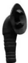
- Water connection assembly 50 mm (pcs: 2)
- User and service manual
- Condensed connection
- 10 meters' signal wire
- Waterproof box
- Winter cover
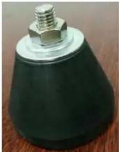
- Anti-vibration base (pcs: 4)
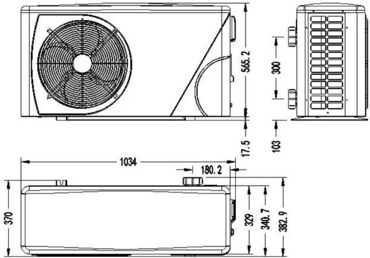
1.2 Dimension
Model: ELYO SMART NN 06/09
text_image
565.2 17.5 300 103 1034 180.2 370 329 340.7 382.91. Description
Models: ELYO SMART NN 12/16
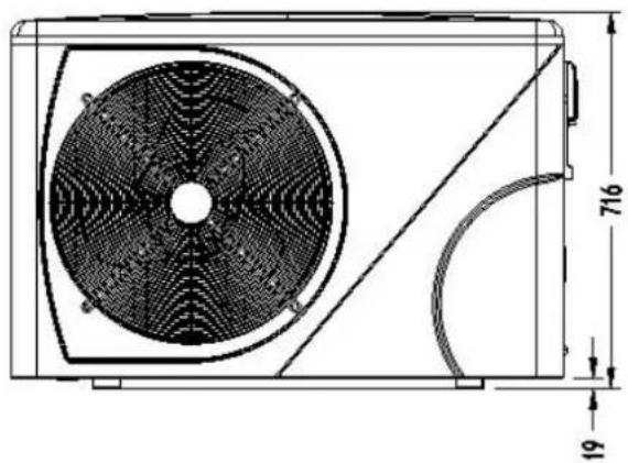
natural_image
Technical line drawing of a mechanical fan or air conditioning unit with dimension annotations (716 and 19) — no readable text or symbols beyond measurement lines.
text_image
390 102.7
text_image
1075.7 127 450 405 417 469.5Models: ELYO SMART NN 20
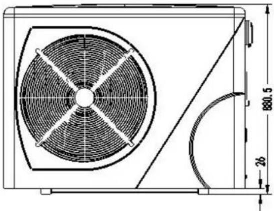
natural_image
Technical line drawing of a fan or vent system with dimension annotations (880.5 and 26) — no readable text or symbols beyond measurement lines.
text_image
600 111.5
text_image
1145.2 141 444 416 424.7 477.31. Description
Models: ELYO SMART NN 25/ 25T, ELYO SMART NN 30/ 30T
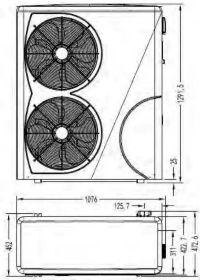
text_image
129.5 25 1076 125.7 452 311 422.7 472.6
text_image
800 86.52. Transport information
2.1 Delivery of the packaging
natural_image
Illustration of a delivery truck and a cardboard box with a pallet jack (no text or symbols)For the transportation, the heat pump is fix on the pallet and cover with a carton box.
To preserve from any damage, the heat pump must be transfer on is pallet.
All material, Even if the transport is chargeable to supplier, can be damaged during its routing at the customer and it is the responsibility of the addressee to make sure of the correspondence of the delivery
The addressee has to written all the reserves at the reception on the delivery note of the carrier if he notices damages of the packaging. DO NOT FORGET TO CONFIRM BY REGISTERED LETTER TO THE CARRIER UNDER 48 H.
2.2 Stock advice
Heat pump must be stored and transfer in vertical position in its original packaging. If it is not the case, she cannot be operated at once, a minimum period of 24H is necessary before to switch on the electrical power.
FORBIDDEN

2.3 Transfer to the final position
During the unpacking of the product and the transfer from is palette of origin to final place, it is necessary to maintain the heat pump vertical position.
Water connection are not there to assure the function of handle, on the contrary support the weight of the heat pump on the water connection must be damage definitively the product. The manufacturer could not be take the responsible in case of damage.
3. Specifications
Technical data ELYO SMART NN pool heat pumps
CE Standard, R410A, Heating and Cooling, Auto mode ,inverter compressor, compressor defrosting, ABS Cabinet
| MODEL | Elyo Smart NN 06 | Elyo Smart NN 09 | Elyo Smart NN 12 | Elyo Smart NN 16 | Elyo Smart NN 20 | |
| CODE | 68769 | 68770 | 68771 | 68772 | 68774 | |
| * Performance at Air 26°C, Water 26°C, Humidity 80% | ||||||
| Heating capacity | kW | 6.1-2.1 | 9.2-2.3 | 12.5-2.9 | 16-3.8 | 19-4.7 |
| Power consumption | kW | 1.097-0.16 | 1.59-0.18 | 2.02-0.22 | 2.66-0.3 | 3.4-0.37 |
| C.O.P. | 13-5.6 | 13-5.8 | 13-6.2 | 12.6-6 | 12.5-5.6 | |
| * Performance at Air 15°C, Water 26°C, Humidity 70% | ||||||
| Heating capacity | kW | 4.7-2.5 | 6.8-1.9 | 9.2-2.2 | 11.5-3 | 14.7-3.9 |
| Power consumption | kW | 1.04-0.35 | 1.51-0.27 | 2-0.31 | 2.55-0.39 | 3.27-0.51 |
| C.O.P. | 7.1-4.5 | 7.1-4.5 | 7.1-4.6 | 7-4.5 | 7-4.5 | |
| * General data | ||||||
| Compressor type | GMCC/TOSHIBA | MITSUBISHI | ||||
| Voltage | V | 220~240V / 50Hz /1PH | ||||
| Rated current | A | 4.4 | 6.9 | 8.5 | 11.7 | 16.3 |
| Minimum fuse | A | 7 | 10 | 13 | 16 | 20 |
| Advised pool volume (with pool cover) | m3 | 10-25 | 12-33 | 15-60 | 25-85 | 55-120 |
| Advised water flux | m3/h | 2.5 | 2.8 | 3.7 | 4.6 | 5.0 |
| Water pressure drop | Kpa | 12 | 12 | 14 | 15 | 18 |
| Heat exchanger | Twist-titanium tube in PVC | |||||
| Water connection | mm | 50 | ||||
| Fan quantity | 1 | |||||
| Ventilation type | Horizontal | |||||
| Fan speed | RPM | 500-850 | 500-650 | 550-850 | 450-650 | |
| Power input of Fan | W | 5-25 | 5-25 | 10-100 | 10-120 | 10-120 |
| Noise level(1m) | dB(A) | 40-50 | 40-52 | 40-52 | 41-54 | 41-54 |
| Refrigerant (R410a) | g | 800 | 950 | 1050 | 1600 | 2300 |
| CO2 equivalent | Tonne | 1.7 | 2.0 | 2.2 | 3.4 | 4.9 |
| * Dimension/ Weight | ||||||
| Net weight | kg | 54 | 54 | 68 | 78 | 98 |
| Gross weight | kg | 66 | 66 | 73 | 83 | 113 |
| Net dimension | mm | 1008*380*577 | 1050*440*709 | 1050*450*870 | ||
| Packing dimension | mm | 1095*430*705 | 1130*470*850 | 1140*480*1010 | ||
* Above data are subjects to modification without notice.
3. Specifications
Technical data ELYO SMART NN pool heat pumps
CE Standard, R410A, Heating and Cooling, Auto mode ,inverter compressor, compressor defrosting, ABS Cabinet
| MODEL | Elyo Smart NN 25 | Elyo Smart NN 25T | Elyo Smart NN 30 | Elyo Smart NN 30T | |
| CODE | 68775 | 68776 | 68850 | 68851 | |
| *Performance at Air 26°C, Water 26°C, Humidity 80% | |||||
| Heating capacity | kW | 24-5.9 | 24-5.9 | 28.5-6.8 | 28.5-6.8 |
| Power consumption | kW | 4.28-0.47 | 4.28-0.47 | 5.09-0.54 | 5.09-0.54 |
| C.O.P. | 12.5-5.6 | 12.5-5.6 | 12.4-5.6 | 12.4-5.6 | |
| * Performance at Air 15°C, Water 26°C, Humidity 70% | |||||
| Heating capacity | kW | 18.9-4.7 | 18.9-4.7 | 23.2-5.6 | 23.2-5.6 |
| Power consumption | kW | 4.2-0.61 | 4.2-0.61 | 5.16-0.73 | 5.16-0.73 |
| C.O.P. | 7-4.5 | 7-4.5 | 7-4.5 | 7-4.5 | |
| ** General data | |||||
| Compressor type | MITSUBISHI | ||||
| Voltage | 220V/50HZ/1PH | 380V/50HZ /3PH | 220V/50HZ /1PH | 380V/50HZ/3PH | |
| Rated current | A | 18.9 | 6.9 | 22.5 | 8.2 |
| Minimum fuse | A | 26 | 9 | 34 | 13 |
| Advised pool volume (with pool cover) | m3 | 65-130 | 65-130 | 75-180 | 75-180 |
| Advised water flux | m3/h | 8.0 | 8.0 | 10.0 | 10.0 |
| Water pressure drop | Kpa | 20 | 20 | 25 | 25 |
| Heat exchanger | Twist-titanium tube in PVC | ||||
| Water connection | mm | 50 | |||
| Ventilation type | Horizontal | ||||
| Fan speed | RPM | 500-850 | |||
| Power input of fan | (10-120)*2 | ||||
| Noise level(1m) | dB(A) | 42-60 | 42-60 | 42-60 | 42-60 |
| Refrigerant (R410a) | g | 3000 | 3000 | 3800 | 3800 |
| CO2 equivalent | Tonne | 6.3 | 6.3 | 80. | 8.0 |
| * Dimension/ Weight | |||||
| Net weight | Kg | 117 | 117 | 128 | 128 |
| Gross weight | Kg | 135 | 135 | 146 | 146 |
| Net dimension | mm | 1050*452*1295 | |||
| Packing dimension | mm | 1130*515*1430 | |||
* Above data are subjects to modification without notice.
4. Accessories and options
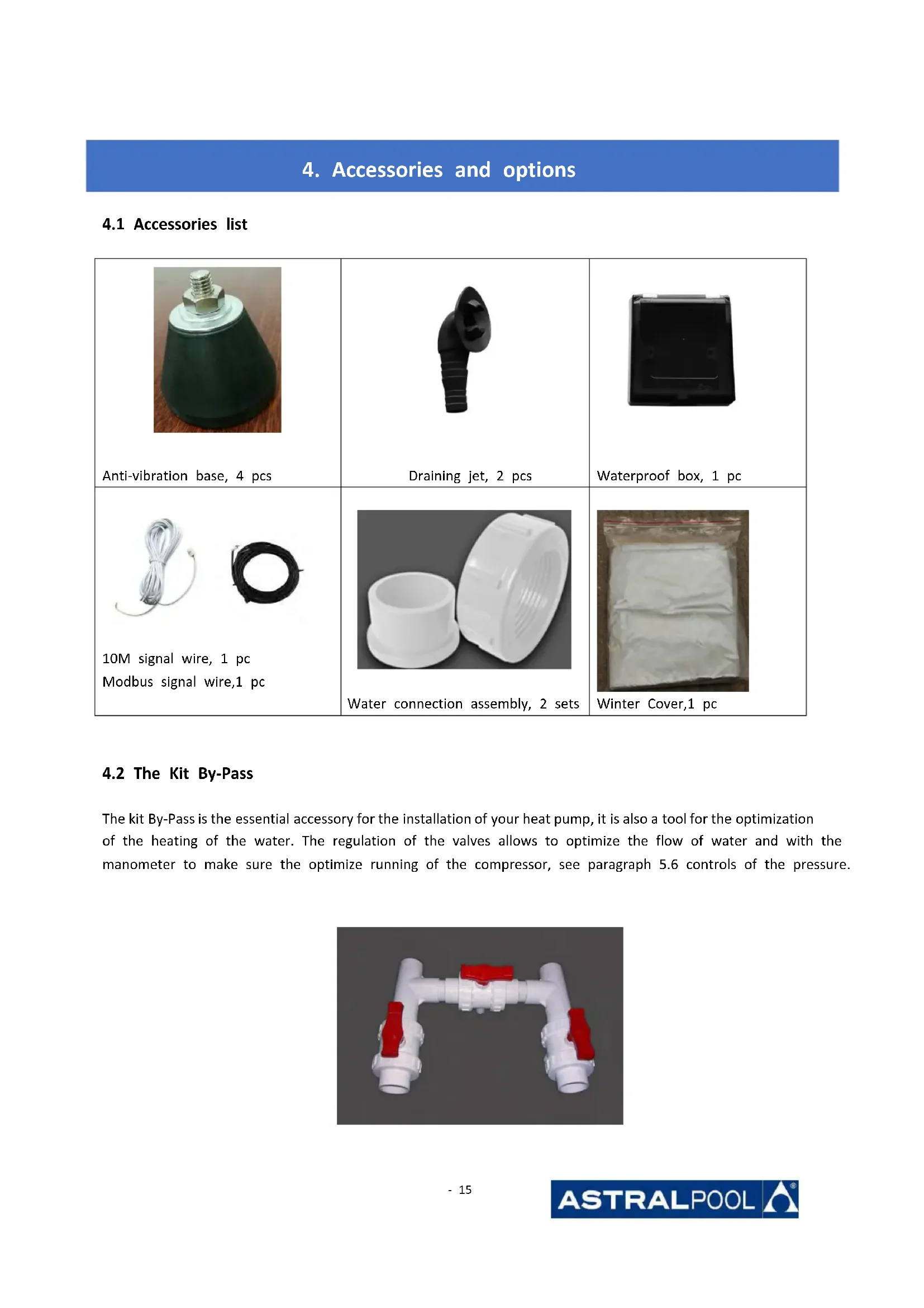
4.1 Accessories list
 Anti-vibration base, 4 pcs Anti-vibration base, 4 pcs |  Draining jet, 2 pcs Draining jet, 2 pcs |  Waterproof box, 1 pc Waterproof box, 1 pc |
 10M signal wire, 1 pcModbus signal wire,1 pc 10M signal wire, 1 pcModbus signal wire,1 pc |  Water connection assembly, 2 sets Water connection assembly, 2 sets |  Winter Cover,1 pc Winter Cover,1 pc |
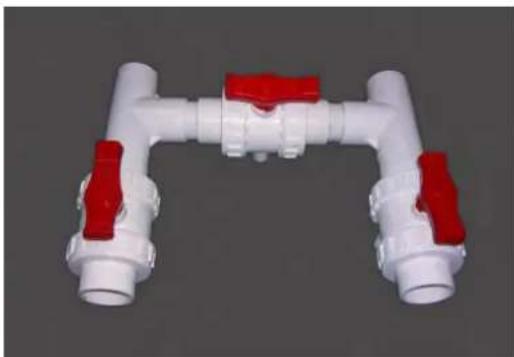
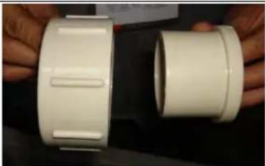
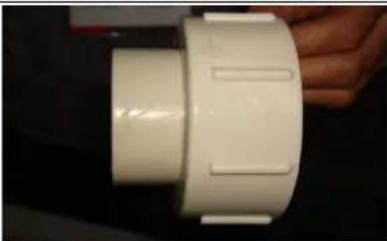
4.2 The Kit By-Pass
The kit By-Pass is the essential accessory for the installation of your heat pump, it is also a tool for the optimization of the heating of the water. The regulation of the valves allows to optimize the flow of water and with the manometer to make sure the optimize running of the compressor, see paragraph 5.6 controls of the pressure.
natural_image
3D rendering of a white and red pipe fitting with flanges (no text or symbols visible)4. Accessories and options
4.3 Accessories Installation
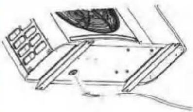
 | Anti-vibration bases1. Take out 4 Anti-vibration bases2. Put them one by one on the bottom of machine like the pictur | |
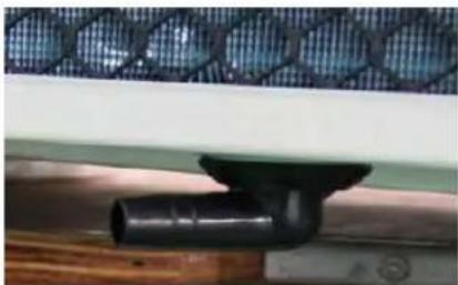 |  | Draining jet1. Install the draining jet under th bottom panel2. Connect with a water pipe to drain out the water.Note: Lift the heat pump to insta the jet. Never overturn the heat pump, it could damage the compressor. |
 |  | Water Inlet & outlet junction1. Install the two joints like the picture shows2. Screw them onto the water Inl & outlet junction |
 |  | Cable wiring1. Open the wiring block box (marked red) on the side of machine2. Fix the other side on joints ins the electric box. |
 |  | Water pump wiring (Dry contact)1. Open the wiring block box (marked red) on the side of machine2. Fix the other side on joints ins the electric box. |
5. Location and connection
ATTENTION:
Please observe the following rules when installing the heat pump:
- Any addition of chemicals must take place in the piping located downstream from the heat pump.
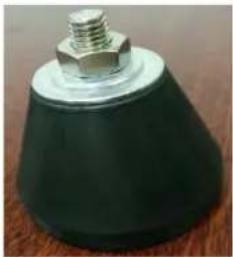
- Always place the heat pump on a solid foundation and use the included rubber mounts to avoid vibration and noise.
- Always hold the heat pump upright. If the unit has been held at an angle, wait at least 24 hours before starting the heat pump.
5.1 Heat pump location
The unit will work properly in any desired location as long as the following three items are present:
-
Fresh air
-
Electricity
-
Swimming pool filters
The unit may be installed in virtually any outdoor location as long as the specified minimum distances to other objects are maintained (see drawing below). Please consult your installer for installation with an indoor pool. Installation in a windy location does not present any problem at all, unlike the situation with a gas heater (including pilot flame problems).
ATTENTION: Never install the unit in a closed room with a limited air volume in which the air expelled from the unit will be reused, or close to shrubbery that could block the air inlet. Such locations impair the continuous supply of fresh air, resulting in reduced efficiency and possibly preventing sufficient heat output.
See the drawing below for minimum dimensions.
5. Location and connection
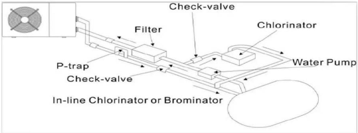
5.2 Check-valve installation

NOTE
Note: If automatic dosing equipment for chlorine and acidity (pH) is used, it is essential to protect the heat pump against excessively high chemical concentrations which may corrode the heat exchanger. For this reason, equipment of this sort must always be fitted in the piping on the downstream side of the heat pump, and it is recommended to install a check-valve to prevent reverse flow in the absence of water circulation. Damage to the heat pump caused by failure to observe this instruction is not covered by the warranty.
text_image
Check-valve Filter P-trap Check-valve In-line Chlorinator or Brominator Chlorinator Water Pump5. Location and connection
5.3 Typical arrangement
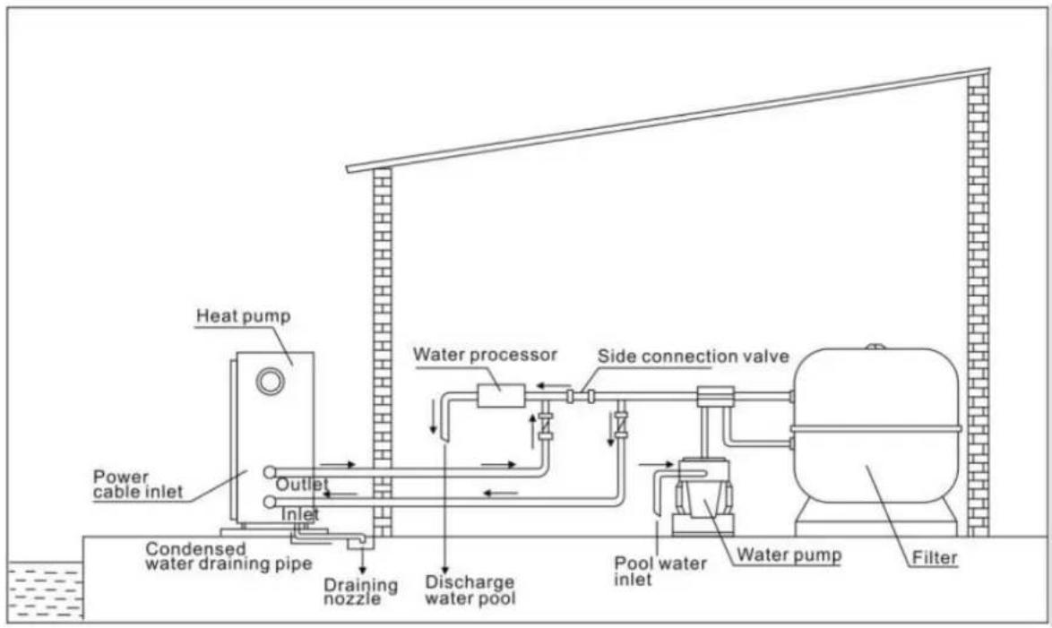
text_image
Heat pump Power cable inlet Outlet Inlet Condensed water draining pipe Draining nozzle Water processor Side connection valve Discharge water pool Pool water inlet Water pump FilterThis arrangement is only an illustrative example.

NOTE
The factory supplies only the heat pump. All other components, including a bypass if necessary, must be provided by the user or the installer.
ATTENTION:
In order to heat the water in the pool (or hot tub), the filter pump must be running to cause the water to circulate through the heat pump. The heat pump will not start up if the water is not circulating.
5. Location and connection
5.4 Initial operation
After all connections, have been made and checked, carry out the following procedure:
- Switch on the filter pump, check for leaks and verify that water is flowing from and to the swimming pool.
- Connect power to the heat pump and press the On/Off button on the LED control panel. The unit will start up after the time delay expires (see below).
- After a few minutes, check whether the air blowing out of the unit is cooler.
- When turn off the filter pump, the unit should also turn off automatically, if not, then adjust the flow switch.
Depending on the initial temperature of the water in the swimming pool and the air temperature, it may take several days to heat the water to the desired temperature. A good swimming pool cover can dramatically reduce the required length of time.

NOTE
Water Flow Switch:
It is equipped with a flow switch for protecting the HP unit running with adequate water flow rate. It will turn on when the pool pump runs and shut it off when the pump shuts off.
Time delay - The heat pump has a built-in 3-minute start-up delay to protect the circuitry and avoid excessive contact wear. The unit will restart automatically after this time delay expires. Even a brief power interruption will trigger this time delay and prevent the unit from restarting immediately. Additional power interruptions during this delay period do not affect the 3-minute duration of the delay.
5. Location and connection
5.5 Condensation
The air drawn into the heat pump is strongly cooled by the operation of the heat pump for heating the pool water which may cause condensation on the fins of the evaporator.

NOTE
The amount of condensation may be as much as several litters per hour at high relative humidity. This is sometimes mistakenly regarded as a water leak.
5.6 Pressure gauge display (R410A)
Examine the pressure gauge which indicates the refrigerant gas pressure of the unit, the below table shows the normal value of the gas pressure (R410A) when the machine is in power off or running conditions.
| Unit Condition | Power Off | |||
| Ambient (°C) | -5~5 | 5~15 | 15~25 | 25~35 |
| Water temp (°C) | / | / | / | / |
| Pressure gauge (Mpa) | 0.68~0.93 | 0.93~1.25 | 1.25~1.64 | 1.64~2.1 |
| Unit Condition | Running | ||||
| Ambient (°C) | / | / | / | / | / |
| Water temp (°C) | 10~15 | 15~20 | 20~25 | 25~30 | 30~35 |
| Pressure gauge (Mpa) | 1.3~1.8 | 1.5~1.9 | 1.6~2.3 | 1.9~2.8 | 2.1~3.5 |
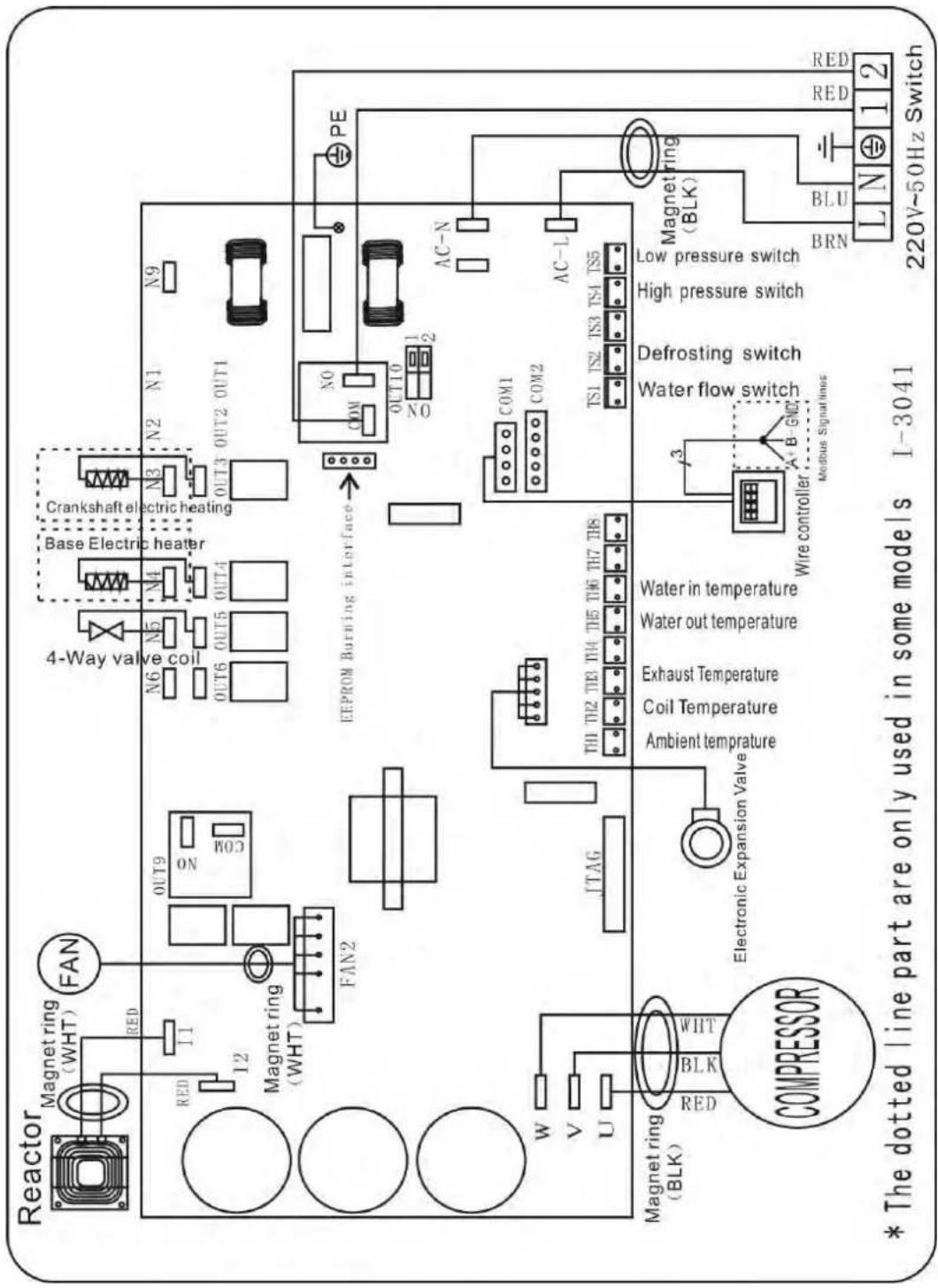
6. Electrical Wiring
6.1 Inverter swimming pool heat pump wiring diagram
Ref. ELYO SMART NN 06/09/12/16/20
Basic electrical wiring
text_image
Reactor Magnet ring (WHT) FAN RED I1 12 Magnet ring (WHT) FAN2 OUT9 ON N6 N5 N4 OUT6 OUT5 OUT4 Crankshaft electric heating N3 N2 N1 N9 OUT3 OUT2 OUT1 EEPROM Burning interface NO COM OUT10 NO PE AC-N AC-L COM1 COM2 TS1 TS2 TS3 TS4 TS5 Magnet ring (BLK) LED BLK WHT Electronic Expansion Valve Ambient temperature Coil Temperature Exhaust Temperature Water out temperature Water in temperature Water in temperature Water in temperature Water in temperature Water in temperature Water in temperature Water in temperature Water in temperature Water in temperature Water in temperature Water in temperature Water in temperature Water in temperature Water in temperature Water in temperature Water in temperature Water in temperature Water in temperature Water in temperature Water in temperature Water in temperature Water in temperature Water in temperature Water in temperature Water in temperature Water in temperature Water in temperature Water in temperature Water in temperature Water in temperature Water in temperature Water in temperature Water in temperature Water in temperatures * The dotted line part are only used in some models I-3041 220V~50Hz Switch6. Electrical Wiring
Electrical Wiring with modbus
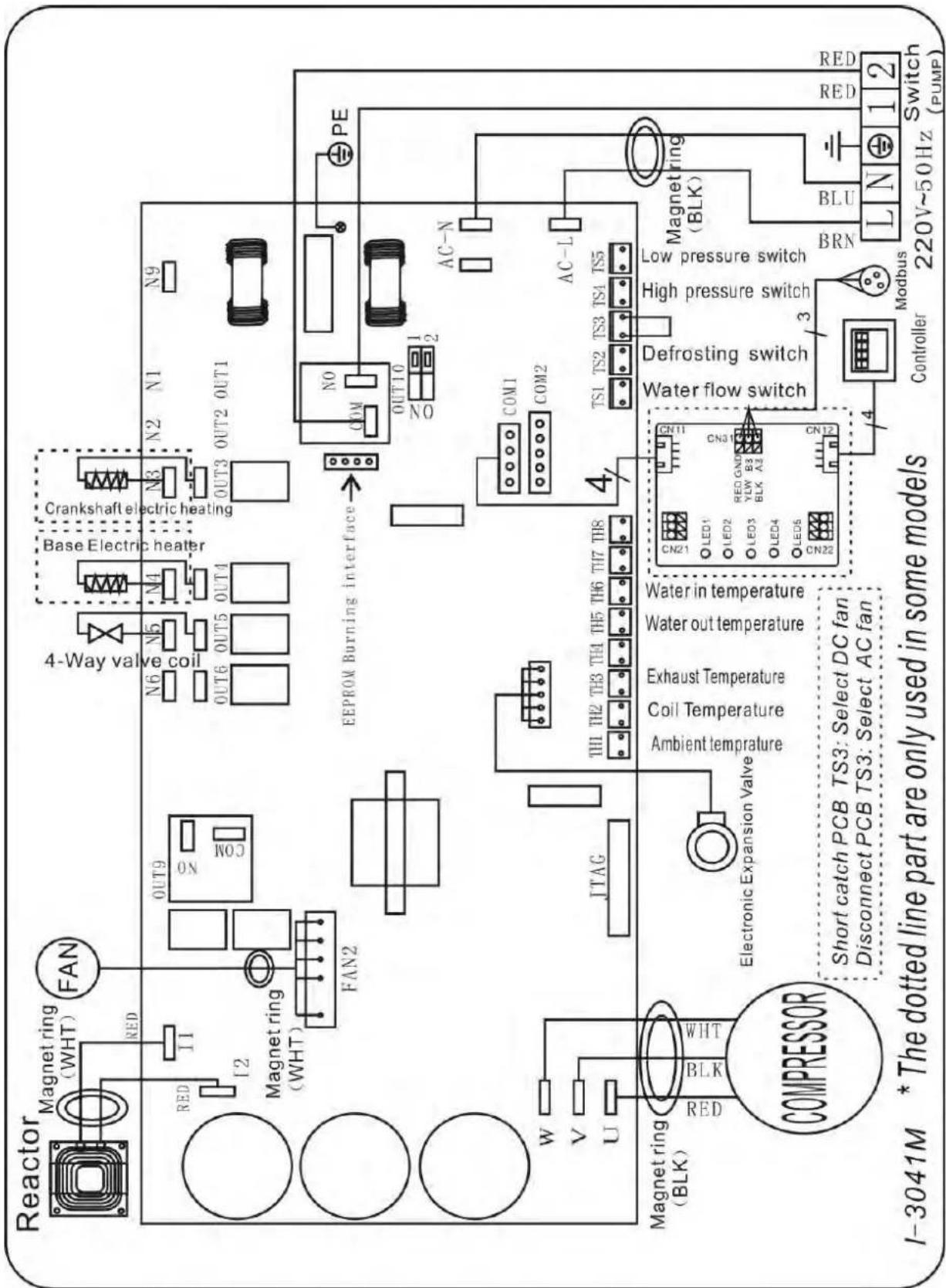
text_image
Reactor Magnet ring (WHT) FAN RED I1 I2 Magnet ring (WHT) FAN2 OUT9 N0 N0C 4-Way valve coil N6 N5 N4 N3 N2 N1 N9 OUT6 OUT5 OUT4 Base Electric heater Crankshaft electric heating OUT3 OUT2 OUT1 EEPROM Burning interface COM NO OUT10 NO 1 2 PE AC-N AC-L W V U Magnet ring (BLK) RED BLK WHT JTAG TH1 TH2 TH3 TH4 TH5 TH6 TH7 TH8 Electronic Expansion Valve Coil Temperature Ambient temperature Exhaust Temperature Water out temperature Water in temperature CAK21 LED1 LED2 LED3 RED GNDY LED4 BLK A2 LED5 CN22 CON11 Water flow switch Defrosting switch High pressure switch Low pressure switch BRN Magnet ring (BLK) BLU L N 1 2 Switch (PUMP) Short catch PCB TS3: Select DC fan Disconnect PCB TS3: Select AC fan Controller Modbus6. Electrical Wiring
6.2 Inverter swimming pool heat pump wiring diagram
Ref. ELYO SMART NN 25/30
Basic electrical wiring
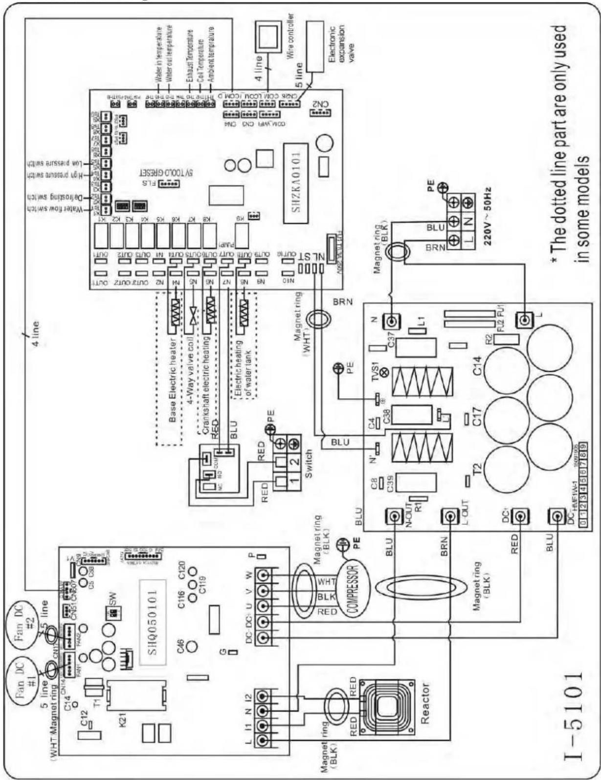
text_image
Water in temperature Water out temperature Exhaust Temperature Coil Temperature Ambient Temperature 4 line Wire controller 5 line Electronic expansion valve SHZKA0101 CNR COIL CONJ. (CONJ. D. THY. TO THE TUR. NO. 500-500A) ON2 COM/WR CND ON Water flow switch Down pressure switch Down cooling switch Drinking switch 4 line Base Electric heater 4-Way valve coil Crankshaft electric heating Electric heating or water tank BLU Magnet ring (WHT) Switch RED PE 1 2 BRN PE N L1 C37 TVS1 C38 C4 R2 F2 P1 T2 C17 BLU N-OUT R1 DC- BLU DC-HFE1W-1 1997/05 0 1 2 3 4 5 6 7 8 9 * The dotted line part are only used in some models SHQ050101 C46 C116 C120 C119 SIHQ050101 C14 CNM CNP CNP CNP CNP CNP CNP CNP CNP CNP CNP CNP CNP CNP CNP CNP CNP CNP CNP CNP CNP CNP CNP CNP CNP CNP CNP CNP CNP CNP CNP CNP CNP CNP CNP CNP CNP CNP CNP CNP CNP CNP CNP CNP CNP CNP CNP CNP CNP CNP CNP CNp SW C45 C116 C120 C119 C14 N 2 3 4 5 6 7 8 9 DC DC U V W P COMPRESSOR Magnet ring (BLK) RED PE BRN Magnet ring (BLK) RED BLU DC HFE1W-1 1997/05 0 1 2 3 4 5 6 7 8 9 I-51016. Electrical Wiring
Electrical Wiring with modbus
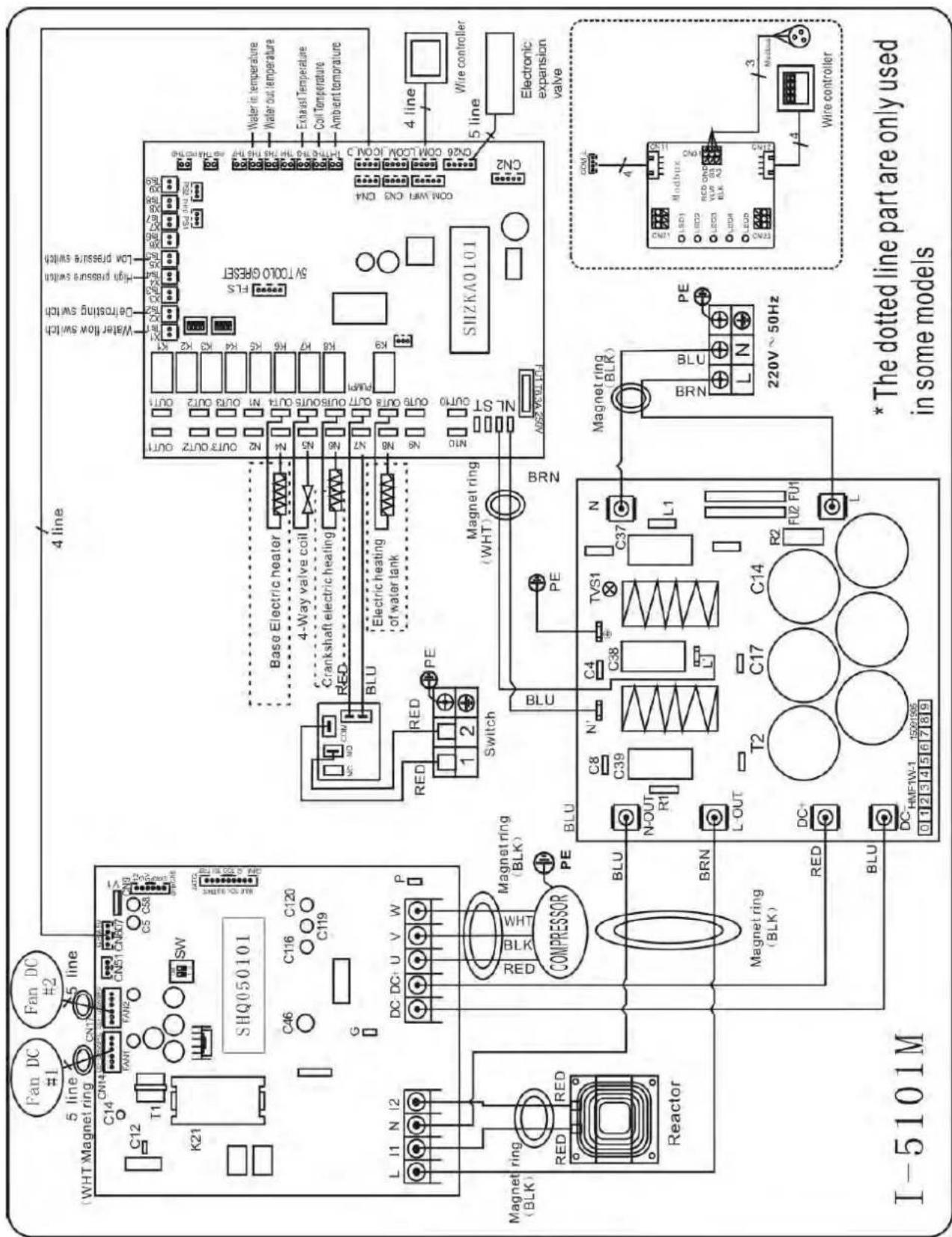
text_image
Fan DC #1 Fan DC #2 WHT Magnet ring CN14 CN17 CN18 CN20 C14 CN14 FANT FAN2 CN51 CN50 CN6 V1 C12 T1 SW K21 K21 SHQ050101 C46 C116 C120 C119 G L I1 N I2 DC DC+ U V W P Magnet ring RED RED COMPRESSOR PE BLU BRN Magnet ring (BLK) BLU T2 C17 C14 R2 FLU FU1 L DC HMF1W-1 1500155 I-5101M 4 line Water flow switch Ce-frosting switch High pressure switch Low pressure switch Base Electric heater 4-Way valve coil Crankshaft electric heating RED BLU Electric heating of water tank RED RED PE Switch Magnet ring (WHT) BRN BLU PE Magnet ring (BLK) BRN L-OUT R1 C39 C4 TVS1 C37 L1 N-OUT PE L-OUT TVS1 N C38 C37 L1 BRN BRN L N PE 220V~50Hz Water in temperature Water out temperature Exhaust Temperature Coil Temperature Ambient temperature COM WFI CN3 CN4 COM COOM CON 5000 RESET SHZKA0101 Wire controller Electronic expansion valve COM L 4 LED1 LED2 LED3 LED4 LED5 LED6 LED7 LED8 LED9 LED bus ON 3 LED bus OUT 4 LED bus OUT 5 LED bus OUT 6 LED bus OUT 7 LED bus OUT 8 LED bus OUT 9 LED bus OUT 10 LED bus OUT 11 LED bus OUT 12 LED bus OUT 13 LED bus OUT 14 LED bus OUT 15 LED bus OUT 16 LED bus OUT 17 LED bus OUT 18 LED bus OUT 19 LED bus OUT 20 LED bus OUT 21 LED bus OUT 22 LED bus OUT 23 LED bus OUT 24 LED bus OUT 25 LED bus OUT 26 LED bus OUT 27 LED bus OUT 28 LED bus OUT 29 LED bus OUT 30 LED bus OUT 31 LED bus OUT 32 LED bus OUT 33 LED bus OUT 34 LED bus OUT 35 LED bus OUT 36 LED bus OUT 37 LED bus OUT 38 LED bus OUT 39 LED bus OUT 40 LED bus OUT 41 LED bus OUT 42 LED bus OUT 43 LED bus OUT 44 LED bus OUT 45 LED bus OUT 46 LED bus OUT 47 LED bus OUT 48 LED bus OUT 49 LED bus OUT 506. Electrical Wiring
6.3 Inverter swimming pool heat pump wiring diagram
Ref. ELYO SMART NN 25T/30T
Basic electrical wiring
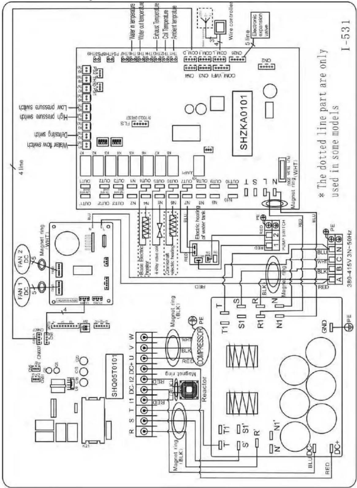
text_image
Water in temperature Water out temperature Exhaust Temperature Coil Temperature Ambient temperature ON26 ON1.1 ON1.1 COMD ON2 Wire controller 5 line Electronic expansion valve SHZKA0101 * The dotted line part are only used in some models I-531 4 line Water flow switch Low pressure switch High pressure switch Detorsing switch Water flow switch Magnet ring WHT1 FAN 2 DC FAN 1 DC CNG07 CNG07 CNG07 CNG07 CNG07 CNG07 CNG07 CNG07 CNG07 CNG07 CNG07 CNG07 CNG07 CNG07 CNG07 CNG07 CNG07 CNG07 CNG07 CNG07 CNG06 CNG06 CNG06 CNG06 CNG06 CNG06 CNG06 CNG06 CNG06 CNG06 CNG06 CNG06 CNG06 CNG06 CNG06 CNG06 CNG06 CNG06 CNG06 CNG06 CNG05T0101 SHQ05T0101 R S T I I DC-12 DC+ U V W W V W R S T I I DC-12 DC+ U V W COMPRESSOR PE RED RED RED RED RED RED RED RED RED RED RED RED RED RED RED RED RED RED RED RED RED RED RED RED RED RED RED RED RED RED RED RED RED RED RED RED RED RED RED RED RED RED RED RED RED RED RED RED RED RED RED RED RED RED RED RED RED RED RED RED RED RED RED RED RED RED RED RED RED RED RED RED RED RED RED RED RED RED RED RED RED RED RED RED RED RED RED RED RED RED RED RED RED RED RED RED RED RED RED RED RED Red LED LED LED LED LED LED LED LED LED LED LED LED LED LED LED LED LED LED LED LED LED LED LED LED LED LED LED LED LED LED LED LED LED LED LED LED LED LED LED LED LED LED LED LED LED LED LED LED LED LED LED LED LED LED LED LED LED LED LED LED LED LED LED LED LED LED LED LED LED LED LED LED LED LED LED LED LED LED LED LED LED LED LED LED LED LED LED LED LED LED LED LED LED LED LED LED LED LED LED LEDLED6. Electrical Wiring
Electrical Wiring with modbus
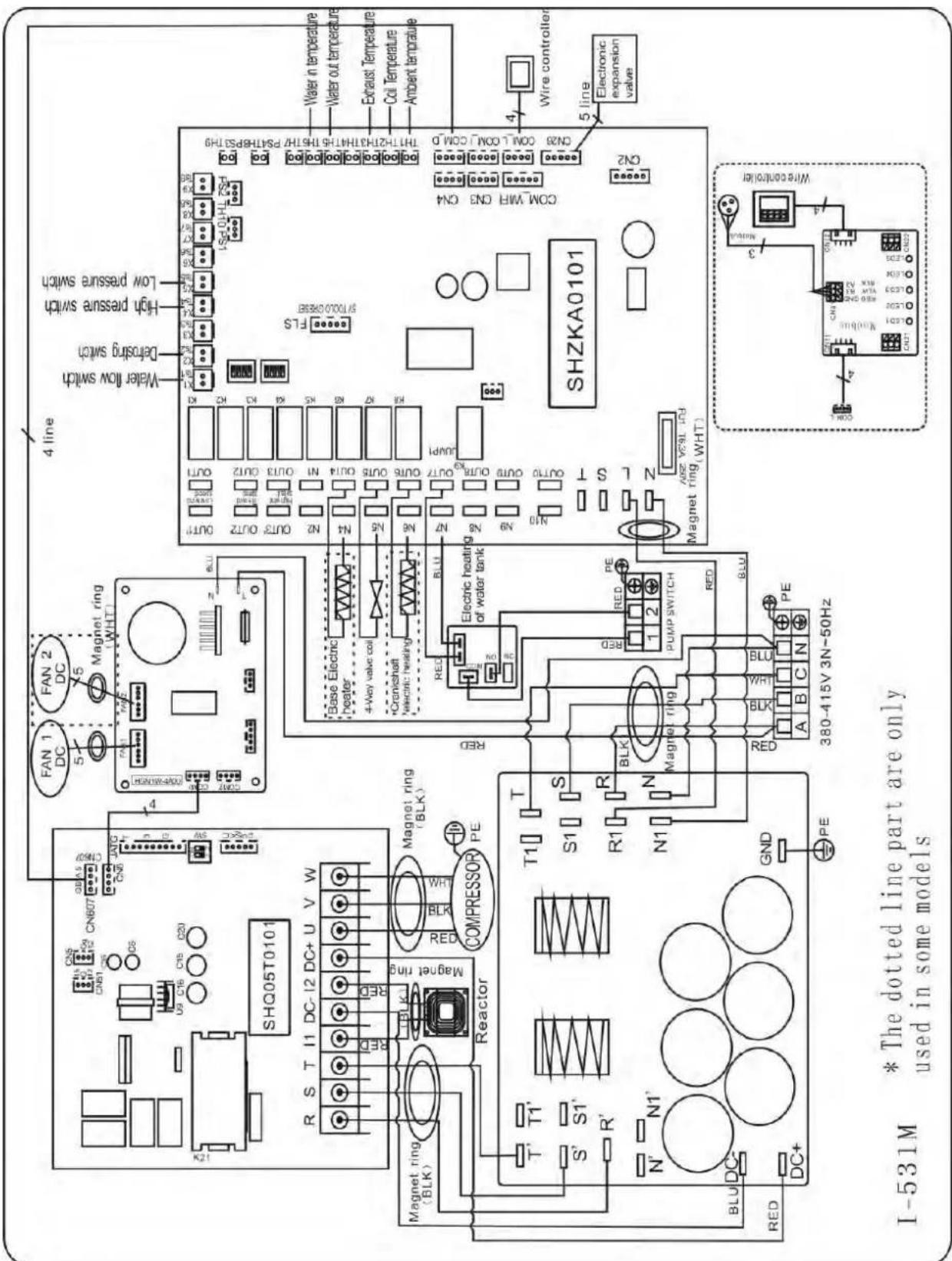
text_image
I-531M * The dotted line part are only used in some models SHQ05T0101 R S T I1 DC-I2 DC+ U V W Magnet ring (BLK) S1 R1 N1 BLU DC- RED DC+ GND PE COMPRESSOR Reactor T1' S' R' T' T1' S1' R' T1' BLU DC- RED P P FAN 1 DC FAN 2 DC Magnet ring (WHT) 4 line Water flow switch Defrosting switch High pressure switch Low pressure switch Base Electric heater 4-Way valve coil *Cranichschaft *electric heating Electric heating of water tank BLU RED BLU N7 N8 N9 N10 OUTR9 OUT17 OUTR10 OUT14 OUTR9 OUT13 OUTR10 OUT12 OUTR9 OUT11 OUTR10 OUT10 OUTR9 OUT9 OUTR10 OUT9 OUTR9 OUT8 OUTR10 OUT7 OUTR9 OUT6 OUTR10 OUT5 OUTR9 OUT4 OUTR10 OUT3 OUTR9 OUT2 OUTR10 OUT1 OUTR9 OUT0 OUTR10 OUT9 OUTR9 OUT8 OUTR10 OUT7 OUTR9 OUT6 OUTR10 OUT5 OUTR9 OUT4 OUTR10 OUT3 OUTR9 OUT2 OUTR10 OUT1 OUTR9 OUT0 OUTR10 OUT9 OUTR9 OUT8 OUTR10 OUT7 OUTR9 OUT6 OUTR10 OUT5 INCHOLPHYSCHYTHOZENZENZENZENZENZENZENZENZENZENZENZENZENZENZENZENZENZENZENZENZENZENZENZENZENZENZENZENZENZENZENZENZENZENZENZENZENZENZENZENZENZENZENZENZENZENZENZENZENZENZENA ZA 3L 1.5Hz SHZKA0101 WIRE CONTROLLER Electronic expansion valve Wire controller* Above electrical wiring diagram only for your reference, please subject machine posted the wiring diagram.
6. Electrical Wiring
6.4 Electrical protection
The power supply for the heat pump must come, preferably, from an exclusive circuit with regulatory protection components (30mA differential protection) and a magneto-thermal switch.
- The electrical installation must be carried out by a specialized professional (electrician) in accordance with the standards and regulations in force in the country of installation.
- The heat pump circuit must be connected to a safety earth circuit at the terminal block.
- The cables must be properly installed to prevent interference.
- The pump is intended for connection to a general power supply with earth connection.
- Section of the cable; This section is indicative and should be checked and adapted according to the needs and conditions of use.
- The tolerance of acceptable voltage variation is +/- 10% during operation.
The connections must be dimensioned according to the power of the device and the state of installation.
| Models | Circuit breaker | Maximum length of the wire | |||
| 2,5 mm^2 | 4 mm^2 | 6 mm^2 | 10 mm^2 | ||
| ELYO SMART NN 06 | 7 A | 84 m | 135 m | 200 m | 335 m |
| ELYO SMART NN 09 | 10 A | 57 m | 90 m | 130 m | 225 m |
| ELYO SMART NN 12 | 13 A | 43 m | 68 m | 100 m | 170 m |
| ELYO SMART NN 16 | 16 A | 34 m | 54 m | 80 m | 135 m |
| ELYO SMART NN 20 | 20 A | 29 m | 45 m | 66 m | 110 m |
| ELYO SMART NN 25 | 26 A | 135 m | 210 m | 315 m | 525 m |
| ELYO SMART NN 25 | 9 A | 105 m | 160 m | 240 m | 400 m |
| ELYO SMART NN 30 | 34 A | 21 m | 34 m | 49 m | 84 m |
| ELYO SMART NN 30 | 13 A | - | 27 m | 39 m | 68 m |

These values are given as a guideline, only the intervention of an authorized t can determine the values corresponding to your installation.
The electric line must be equipped with a ground connection and with a circuit br difference 30mA in head.
6. Electrical Wiring
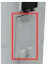
6.5 Installation of the display deportee
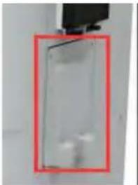
Photo(1) Photo(2) Photo(3) Photo(4) Photo(5)
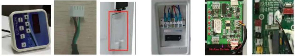
- The side with plug connects with the control panel (photo1)
- The other side of the signal wire. (photo2)
- Open the wiring panel and put the side without plug through the electrical box. (photo3,4)
- Insert the wiring into the designated position on the Modbus Module or PCB(without Modbus). (photo5)
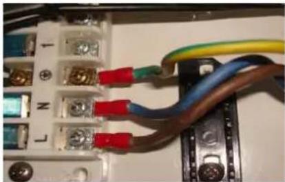
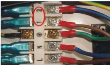
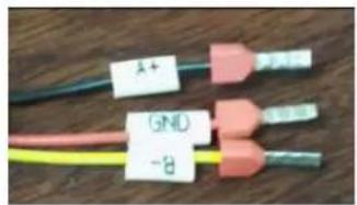
6.6 Installation of the Modbus /Fluidra Connect Signal Wire
Photo(6) Photo(7) Photo(8) Photo(9)
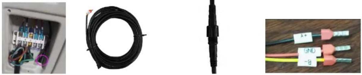
- Open the terminal cover (photo6)
- Take the Modbus /Fluidra Connect signal wire from the accessories (photo7) and put the round end of the signal wire into the signal wire from Modbus Module. (photo 8)
- Three wire terminal: "A+", "B-", "GND" (Photo 9)
6. Electrical Wiring
Dry contact timer connection
Timer
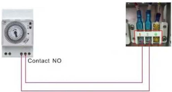
text_image
Contact NODry contact pump connection
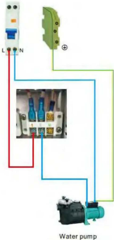
text_image
L N Water pump7. Start-up of the Heat Pump
7. Display Controller Operation
7.1. Guide for operation
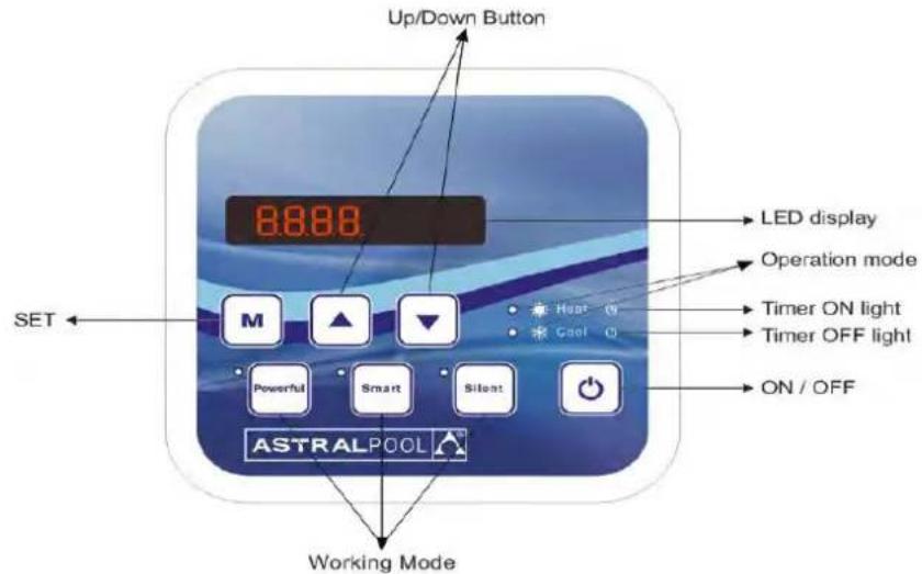
text_image
Up/Down Button 8:88:88 LED display Operation mode Timer ON light Timer OFF light ON / OFF SET M ▲ ▼ Heat 0 Cool 0 Powerful Smart Silent ASTRALPOOL Working ModeWhen the heat pump connects to the power, the LED display shows a code for 3 seconds which indicates the heat pump model.
7.2 The keys and their operations
7.2.1 button
Press ☐ to start the heat pump unit, the LED display shows the desired water temperature for 5 seconds, then shows the inlet water temperature and the operation mode.
Press to stop the heat pump unit and show "OFF"
Notice : During the parameter checking and setting, press the to quick-exit and save the current setting. Press again to turn on/off the machine.
7.2.2 button
Press for 5 seconds to switch the heating mode and auto mode.
7.2.3 and button
Clock/unclock the display:
Hold and for 5 seconds to lock/Unlock the display.
Water temperature setting:
Press or to set the water temperature directly.
7. Start-up of the Heat Pump
Parameter checking:
Press first, then press to check the User parameter from d0 to d14
| Code | Condition | Scope | Remark |
| d0 | IPM mould temperature | 0-120°C | Real testing value |
| d1 | Inlet water temp. | -9°C~99°C | Real testing value |
| d2 | Outlet water temp. | -9°C~99°C | Real testing value |
| d3 | Ambient temp. | -30°C~70°C | flash if Real value<-9 |
| d4 | Frequency limitation code | 0,1,2,4,8,16 | Real testing value |
| d5 | Piping temp. | -30°C~70°C | flash if Real value<-9 |
| d6 | Gas exhaust temperature | 0°C~C5°C (125°C) | Real testing value |
| d7 | Step of EEV | 0~99 | N*5 |
| d8 | Compressor running frequency | 0~99Hz | Real testing value |
| d9 | Compressor current | 0~30A | Real testing value |
| d10 | Current fan speed | 0-1200 (rpm) | Real testing value |
| d11 | Error code for last time | All error code | |
| d12 | MOBUS COM | 0 - 5 | Setting, Modbus Only |
| d13 | MODBUS ID Address | 1 - 88 | Setting, Modbus Only |
| d14 | Product Code | 0000- FFFF | Setting, Modbus Only |
Remark:
d4: Frequency limitation code,
0: No frequency limit;
1: Coil pipe temperature limit;
2: Overheating or overcooling frequency limit;
4: Drive Current frequency limit;
8: Drive voltage frequency limit;
16: Drive high temperature frequency limit
7. Start-up of the Heat Pump
Press first, then press to check/adjust the User parameter from P1 to P7
| Code | Name | Scope | Default | Remark |
| P0 | Mandatory defrosting | 0-1 | 0 | 0: Default normal operation1: mandatory defrosting. |
| P1 | Working mode | 0-1 | 1 | 1: Heating mode, 0: cooling mode, |
| P2 | Timer on/off | 0-1 | 0 | 1 Timer on/off is under function Timer on/off is out of function (The setting of P5 and P6 won't work) |
| P3 | Water pump | 0-1 | 0 | 1: Always running;0: Depends on the running of compressor |
| P4 | Current time | HH:MM | 00: 00 | 0-23:0-59 |
| P5 | Timer on | HH:MM | 00: 00 | 0-23:0-59 |
| P6 | Timer off | HH:MM | 00: 00 | 0-23:0-59 |
| P7 | Water temp. calibration | -9~9 | 0 | Default setting: 0 |
| P12 | MOBUS COM | 0 - 5 | 0 | Modbus Only (default value after reset) |
| P13 | MODBUS ID Address | 1 - 88 | 9 | Modbus Only (default value after reset) |
| Code with connect | Parameter P | Description |
| 68769 | 0CA1 | ELYO SMART NN 6.1-2.1 |
| 68770 | 0CA2 | ELYO SMART NN 9.2-2.3 |
| 68771 | 0CA3 | ELYO SMART NN 12.5-2.9 |
| 68772 | 0CA4 | ELYO SMART NN 16-3.8 |
| 68774 | 0CA6 | ELYO SMART NN 19-4.7 |
| 68775 | 0CA7 | ELYO SMART NN 24-5.9 |
| 68776 | 0CA8 | ELYO SMART NN 24-5.9 T |
| 68850 | 0CF2 | ELYO SMART NN 28.5-6.8 |
| 68851 | 0CF3 | ELYO SMART NN 28.5-6.8 T |
Product code parameter P (Modbus Only): Press + for 5 second, the first digital number flashes, press
or to choose the target number from 0-F, then press go to adjust the second number. So does the
third and forth number. Lastly press to save the setting and exit, or it automatically exit after 15 seconds.
After the setting, the product code parameter P couldn't be reset, even if system reset, Its setting value is always retained.
7. Start-up of the Heat Pump
7.2.4 System reset function

Press
in 10s, the system will reset and display "0000" on the controller.
7.2.5

Symbol of heating, the light will be on when it is in operation. When defrosting, the light will flash.
7.2.6

Symbol of cooling, the light will be on when it is in operation.
7.2.7

Symbol of automatic stop, the light will be on when it is in operation.
7.2.8

Symbol of automatic start, the light will be on when it is in operation.
7.2.9

Press this button, the light will be flash, the heat pump will operate in 'Full output' only.
7.2.10

While you choose the Smart, the heat pump will just operate in 'Medium output' and 'Full output' When in 'Medium output', the light of Smart will flash. When in 'Full output', the lamp of Smart is lighting, the lamp of Powerful will be flash.
7.2.11

While you choose the Silent, the heat pump will just operate in 'Medium output' and 'Small output' When in 'Small output', the light of Silent will flash. When in 'Medium output', the lamp of Silent is lighting, the lamp of Smart will be flash.
7. Start-up of the Heat Pump
7.2.12 Auto Mode
There are 3 models for the unit, Heating only, Auto mode(heating and cooling switch), Cooling only.
You can switch Heating only and Auto mode by pressing for 5 seconds, no matter the unit is on or off.
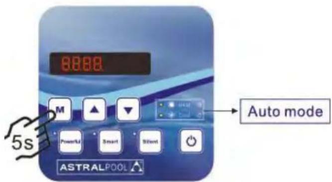
text_image
8888 M ▲ ▼ Powerful Smart Silent Auto mode ASTRALPOOL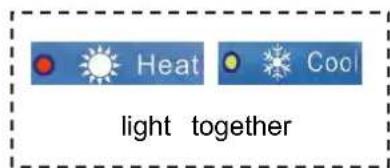
text_image
Heat Cool light together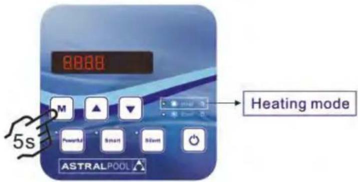
text_image
8888 M ▲ ▼ Powerful Smart Still ASTRALPOOL Heating mode 5s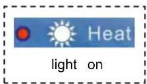
text_image
Heat light onOperation logic of Auto Mode
| Set water temperature (Tset) | Current water in temperature (Tset +2C) | Current working mode | After 3 minutes or ab it will switch to |
| Tset (eg: 28) | Tset +2C (eg:30°C) | Heating mode | Cooling mode |
| Tset (eg: 28°C) | Tset-2°C(eg: 26°C) | Cooling mode | Heating mode |
7. Start-up of the Heat Pump
7.3 Heating operation logic
| NO | Working status | Working mode | Water in temperature | Heat pump working leve |
| 1 | Start-up of heat pump | SMART | ≤q Tset-1 | POWERFUL |
| 2 | Tset-1< and < Tset+1 | SMART | ||
| 3 | ≥q Tset+1 | Standby | ||
| 4 | SILENT | ≤q Tset-1 | SMART | |
| 5 | Tset-1< and < Tset+1 | SILENT | ||
| 6 | ≥q Tset+1 | Standby | ||
| 7 | POWERFUL | powerful | POWERFUL | |
| 8 | ≥q Tset+1 | Standby | ||
| 9 | Restart heating from standby status is the same as the Start-up | |||
7.4 Cooling operation logic
| NO | Working status | Working mode | Water in temperature | Heat pump working leve |
| 1 | Start-up of heat pump | SMART | ≤q Tset-1 | Standby |
| 2 | Tset-1< and <Tset+1 | SMART | ||
| 3 | ≥q Tset+1 | POWERFUL | ||
| 4 | SILENT | ≤q Tset-1 | Standby | |
| 5 | Tset-1< and <Tset+1 | QUIET | ||
| 6 | ≥q Tset+1 | SMART | ||
| 7 | POWERFUL | >Tset-1 | POWERFUL | |
| 8 | ≤q Tset-1 | Standby | ||
| 9 | Restart cooling from standby status is the same as the Start-up | |||
8. Troubleshooting
8.1 Error code display on LED wire controller
| Malfunction | Error code | Reason | Solution |
| Inlet water temperature sensor failure | PP01 | 1. The sensor in open or short circuit2. The wiring of sensor is loose | 1. Check or change the sensor2.Re-fix the wiring of the sensors |
| Outlet water temperature sensor failure | PP02 | 1. The sensor in open or short circuit2. The wiring of sensor is loose | 1. Check or change the sensor2.Re-fix the wiring of the sensors |
| Heating piping sensor failure | PP03 | 1. The sensor in open or short circuit2. The wiring of sensor is loose | 1. Check or change the sensor2.Re-fix the wiring of the sensors |
| Gas return sensor failure | PP04 | 1. The sensor in open or short circuit2. The wiring of sensor is loose | 1. Check or change the sensor2.Re-fix the wiring of the sensors |
| Ambient temperature sensor failure | PP05 | 1. The sensor in open or short circuit2. The wiring of sensor is loose | 1. Check or change the sensor2.Re-fix the wiring of the sensors |
| Exhaust piping sensor failure | PP06 | 1. The sensor in open or short circuit2. The wiring of sensor is loose | 1. Check or change the sensor2.Re-fix the wiring of the sensors |
| Antifreeze protection in Winter | PP07 | Ambient temperature or water inlet temperature is too low | Normal protection |
| Low ambient temperature protection | PP08 | 1.Beyond the scope of using environment2. Sensor abnormality | 1. Stop using, beyond the scope of using2.Change the sensor |
| Piping temperature too high protection under cooling mode | PP10 | 1. Ambient temperature is too high of the water temperature is too high in cooling mode2. Refrigeration system is abnormal | 1. Check the scope of using2. Check refrigeration system |
| T2 water temp. Too lo protection under cooling mode | PP11 | 1. Low water flow2. T2 temperature sensor abnormal | 1. Check water pump and waterway system2. Change T2 temperature sensor |
| High pressure failure | EE01 | 1. Ambient temperature is too high2. Water temperature is too high3. Water flow is too lowFan motor speed is abnormal or fan mo damaged | 1. Check the water flow or water pump2. Check the fan motor3. Check and repair the piping system |
| Low pressure failure | EE02 | 1. EEV has blocked or pipe system is jammed2. Motor speed is abnormal or motor has damaged3. Gas leakage | 1. Check the EEV and piping syste Check the motor2. Through the high pressure gaug to check the pressure value |
| Water flow failure | EE03Or” ON” | 1. Water flow switch is damaged2. No/ Insufficient water flow. | 1. Change the water flow switch2. Check the water pump or the wa system |
| Over heating protection for water temperature (T in heating mode) | EE04 | 1. Low water flow2. Water flow switch is stuck and the water supply is cut off3. T2 sensor is abnormal | 1. Check the water way system2. Check the water pump or water flow switch3. CheckT2 sensor or change another |
8. Troubleshooting
| Malfunction | Error code | Reason | Solution |
| T6 Exhaust too high protection | EE05 | 1.Lack of gas2.Low water flow3.Pipingsystem has been blocked4.Exhaust temp. Sensor failure | 1. Check the high pressure gauge, if too with some gas2. Check the waterway system and water3. Check the piping system if there was block4. Change a new exhaust temp. sensor |
| Controller failure | EE06 | 1. Wire connection is not good, or dam signal wire2. Controller failure | 1. Check and re-connect the signal wire2. Change a new signal wire3. Turn off electricity supply and restart r4. Change anew controller |
| Compressor current protection | EE07 | 1. The compressor current is too large instantaneously2. Wrong connection for compressor phas sequence3.Compressor accumulations of liquid and lead to the current becomes larger4. Compressor or driver board damaged5. The water flow is abnormal6. Power fluctuations within a short time | 1. Check the compressor2. Check the waterway system3. Check if the power in the normal range4. Check the phase sequence connectio |
| Communication failure between controller and main board | EE08 | 1. Poor signal wire connection or damage signal wire2. Controller malfunction | 1. Check and re-connect the signal wire2. Change a new signal wire3. Turn off electricity supply and restart r4. Change anew controller |
| Communication failure between Main control board and Driving board | EE09 | 1. Poor connection of communication wir2. The wire is damaged | 1. Check the wire connection2. Change a new wire |
| VDC voltage too high protection | EE10 | 1. Mother line voltage is too high2. Driver board is damaged. | 1. Check if the power is in the normal:2. Change driver board or main board |
| IPM module protection | EE11 | 1. Data mistake2. Wrong compressor phase connection3. Compressor liquid and oil accumulation lead to the current becomes larger4. Compressor or driver board damaged | 1. Program error, turn off electricity supply restart after 3 minutes2. Change driver board3. Check compressor sequence connection |
| VDC voltage too low protection | EE12 | 1. Mother line voltage is too low2. Driver board is damaged. | 1. Check if the power is in the normal:2. Change driver board |
8. Troubleshooting
| Malfunction | Error code | Reason | Solution |
| Input current over high protection. | EE13 | The compressor current is too large momentaryThe water flow is abnormalPower fluctuations within a short timeWrong PFC inductor | Check the compressorCheck the waterway systemCheck if the power is in the normal rangeCheck if the correct PFC inductor is used |
| IPM module thermal circuit is abnormal | EE14 | Output abnormality of IPM module thermal circuitFan blade is broken | Change a driver boardCheck if the motor speed is too low or fan motor damaged, change another oneChange another fan blade |
| IPM module temperature too high protection | EE15 | Output exception of IPM module thermal circuitMotor is abnormal or damagedFan blade is broken | Change a driver boardCheck if the fan motor speed is too low or fan motor damaged, change another oneChange another fan blade |
| PFC module protection | EE16 | Output exception of PFC moduleMotor is abnormal or damagedFan blade is brokenInput voltage leap, input power abnormal | Change a driver boardCheck if the motor speed is too low or fan motor damaged, change another oneChange another fan bladeCheck the input voltage |
| DC fanmotor failure | EE17 | DC motor is damagedMain board is damagedThe fan blade is stuck | Detect DC motor, replace with a new oneChange a new main boardFind out the barrier and wor it out |
| PFC module thermal circuit is abnormal | EE18 | The driver board is damaged | Change a new driver boardCheck if the fan motor speed too low or fan motor damaged, change another one |
| PFC module high temperature protection | EE19 | PFC module thermal circuit output abnormalMotor is abnormal or damagedFan blade is brokenThe screw in the driver board is not tight | Change a new driver boardCheck if the motor speed is too low or fan motor damaged, change another oneChange another fan bladeCheck if the screw is loose |
| Input power failure | EE20 | The supply voltage fluctuates too much | Check whether the voltage is stable |
8. Troubleshooting
| Malfunction | Error code | Reason | Solution |
| Software control exception | EE21 | 1. Compressor runs out of step2. Wrong program3. Impurity inside compressor cause the unstable rotate speed | 1. Check the main board or change a new one2. Enter correct program |
| Current detection circuit failure | EE22 | 1. Voltage signal abnormal2. Driver board is damaged | 1. Check the main board or change a new one2. Change a new driver board |
| Compressor start failure | EE23 | 1. Main board is damaged2. Compressor wiring error or poor contact or unconnected3. Liquid accumulation inside4. Wrong phase connection for compressor | 1. Check the main board or change a new one2. Check the compressor wiring according to the circuit diagramCheck the compressor or change a new one |
| Ambient Temperature device failure on Driver board | EE24 | Ambient Temperature device failure | Change driver board or main board |
| Compressor phase failure | EE25 | Compressors U, V, W are connected to one phase or two phases. | Check the actual wiring according to the circuit diagram |
| Four-way valve reversal failure | EE26 | 1. Four-way valve reversal failure2. Lack of refrigerant (no detect when T3 or T5 malfunction) | 1. Switch to Cooling mode to check the 4-way valve if it has been reversed correctly2. Change a new 4-way valve3. Fill with gas |
| EEPROM data read malfunction | EE27 | 1. Wrong EEPROM data in the program or failed input of EEPROM data2. Main board failure | 1. Re-enter correct EEPROM data2. Change a new main board |
| The inter-chip communication failure on the main control board | EE28 | Main board failure | 1. Turn off electricity supply and restart it2. Change a new main board |
8. Troubleshooting
8.2 Other Malfunctions and Solutions (No display on LED wire controller)
| Malfunctions | Observing | Reasons | Solution |
| Heat pump is not running | LED wire controller no display. | No power supply | Check cable and circuit breaker if it is connected |
| LED wire controller.Displays the actual time. | Heat pump under standby status | Startup heat pump to run. | |
| LED wire controller displays the actual water temperature. | 1. Water temperature is reaching to setting value, HP under constant temperature status.2. Heat pump just starts to run.3. Under defrosting. | 1. Verify water temperature setting.2. Startup heat pump after a few minutes.3. LED wire controller should display "Defrosting". | |
| Water temperature is cooling when HP runs under heating mode | LED wire controller displays actual water temperature and no error code displays. | 1. Choose the wrong mode.2. Figures show defects.3. Controller defect. | 1. Adjust the mode to proper running2. Replace the defect LED wire controller, and then check the status after changing the running mode, verifying the water inlet and outlet temperature.3. Replace or repair the heat pump unit |
| Short running | LED displays actual water temperature, no error code displays. | 1. Fan NO running.2. Air ventilation is not enough.3. Refrigerant is not enough. | 1. Check the cable connections between the motor and fan, if necessary, it should be replaced.2. Check the location of heat pump unit, and eliminate all obstacles to make good air ventilation.3. Replace or repair the heat pur unit. |
| water stains | Water stains on heat pump unit | 1. Concreting.2. Water leakage. | 1. No action.2. Check the titanium heat exchanger carefully if it is any defect. |
| Too much ice on evaporator | Too much ice on evaporator. | 1. Check the location of heat pump unit, and eliminate all obstacles to make good air ventilation.2. Replace or repair the heat pump unit. |
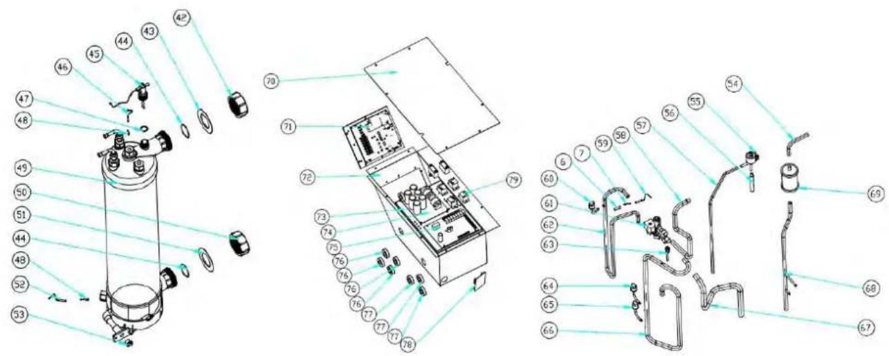
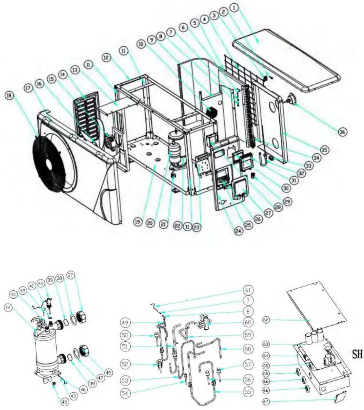
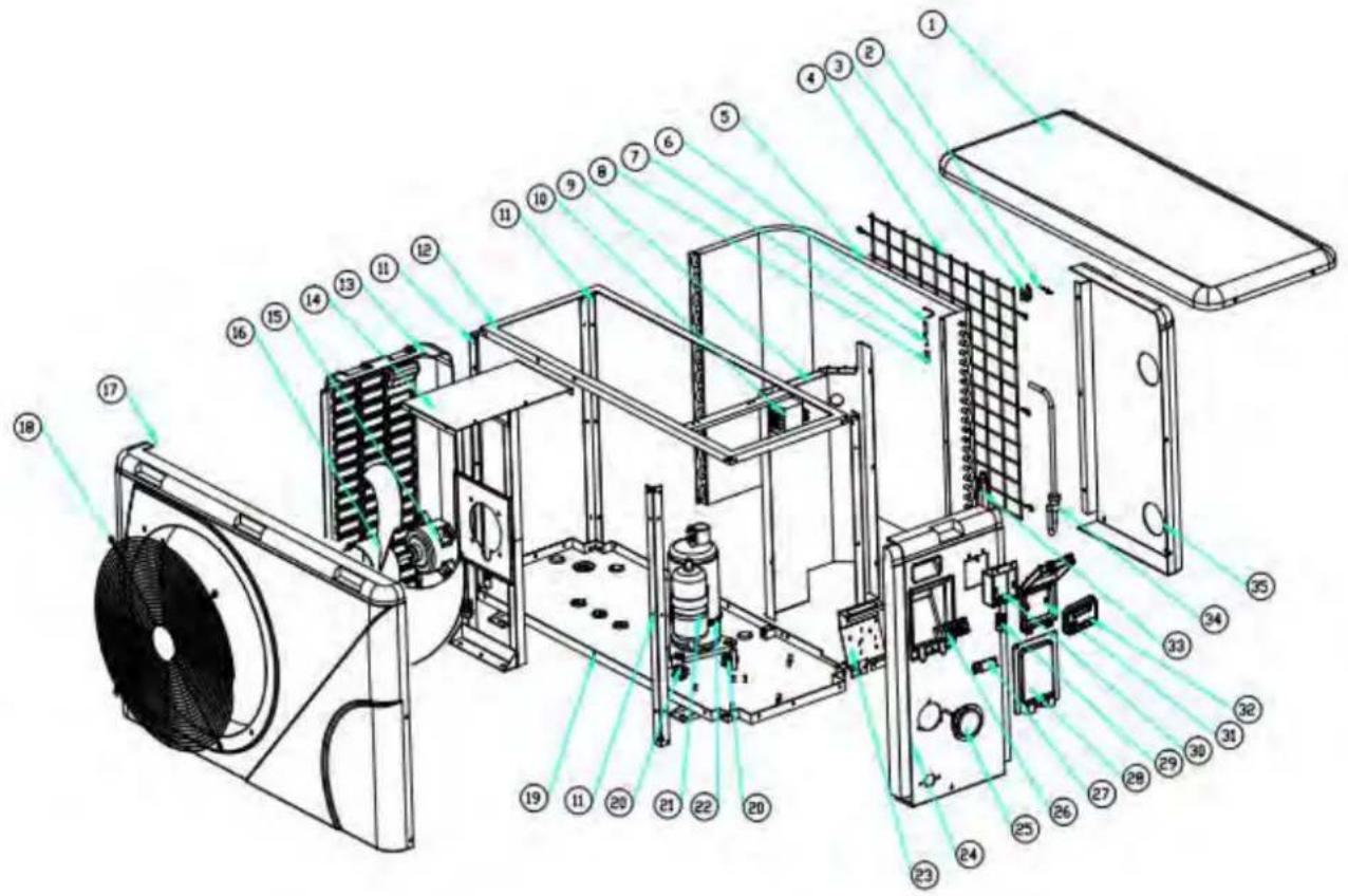
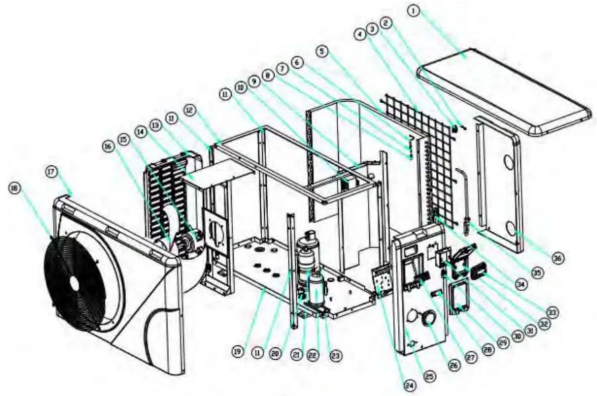
9. Exploded Diagram
9. 1 Exploded Diagram
Model: ELYO SMART NN 06/09
9. Exploded Diagram
9.2 Part list
Model : ELYO SMART NN 06/09
| No. | Parts name | 68769 | 68770 | No. | Parts name | 68769 | 68770 |
| 1 | Top cover | 133050022 | 35 | Back Panel | 1330500562 | ||
| 2 | Ambient temp. sensor TH | 117110020 | 36 | Pressure gauge | 110800001 | ||
| 3 | Ambient temp. sensor cli | 133020010 | 37 | Water connection sets | 113900082 | ||
| 4 | Back grill | 108140012 | 38 | Red rubber ring | 133020012 | ||
| 5 | Evaporator | 103000199/103000195 | 39 | Rubber ring on water | 133020026 | ||
| 6 | Pipe temp. sensor TH2 | 117110004 | 40 | Water flow switch | 112100021-1 | ||
| 7 | Temperature sensor | 113190001 | 41 | Sealing ring | 116000001-2 | ||
| 8 | Temperature sensor | 42 | Water out temp. sensor TH | 117110011 | |||
| 9 | Isolation panel | 108030096/108140066 | 43 | Exchanger temperature | 108010025 | ||
| 10 | Reactor | 117230003 | 44 | Titanium heat exchanger | 102040585/102040501 | ||
| 11 | Pillar | 108140015 | 45 | Drainage plug | 150000110 | ||
| 12 | Top frame | 180140052 | 46 | Water in temp. sensor TH | 117110012 | ||
| 13 | Fan motor bracket | 180140056 | 47 | Blue rubber ring | 133020011 | ||
| 14 | Left side panel | 133050057 | 48 | Water connection sets | 113900082 | ||
| 15 | Fan motor | 112000041 | 49 | Exhaust piping | 113010182 | ||
| 16 | Fan blade | 132000010 | 50 | High pressure switch | 116000066 | ||
| 17 | Front panel | 133050008 | 51 | Exchanger to EEV | 113070036 | ||
| 18 | Front grill | 1081400113 | 52 | EEV | 119000017 | ||
| 19 | Base tray | 108140051 | 53 | EEV to distribution pipe | 113080060 | ||
| 20 | Compressor | 101000142 | 54 | Suction valve | 120000023 | ||
| 21 | Compressor damping feet | 136020019 | 55 | Gas return piping | 113020258 | ||
| 22 | Compressor heating belt | 142000072 | 56 | Low pressure switch | 116000069 | ||
| 23 | Terminal box | 108160024 | 57 | Low pressure switch | 116000070 | ||
| 24 | Right side panel | 1330500552 | 58 | 4-way valve to collective | 113060094 | ||
| 25 | 5-bit terminal | 115000004 | 59 | 4-way valve to exchanger | 113030091 | ||
| 26 | Clip | 136010004 | 60 | 4 way valve | 121000020 | ||
| 27 | Terminal blocks plastic | 133050026 | 61 | Exhaust temp. sensor TH3 | 117110021 | ||
| 28 | Wiring box | 108010018 | 62 | Electric box cover | 108030059 | ||
| 29 | Connector of cable | 110000008 | 63 | Inverter PCB | 117100014-V1.5 | ||
| 30 | Controller | 117020150 | 64 | Electric box | 108030095 | ||
| 31 | Waterproof controller box | 113712007 | 65 | magnet ring | 117240002 | ||
| 32 | Distributor assembly | 113040093 | 66 | magnet ring | 117240003 | ||
| 33 | Rubber block | 136020018 | 67 | Modbus module | 117010095 | ||
| 34 | Collective assembly | 113050108 | |||||
9. Exploded Diagram
Model: ELYO SMART NN 12
text_image
Exploded view diagram of an air conditioning unit with numbered components for identification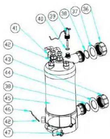
text_image
Technical diagram of a cylindrical mechanical device with numbered components and light ray paths indicating assembly or inspection.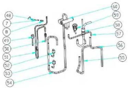
text_image
Technical diagram of a piping system with numbered components and flow lines indicating fluid paths or connections.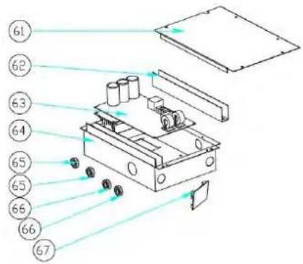
text_image
Technical diagram of a mechanical device with numbered components and light rays indicating motion or flow9. Exploded Diagram
Model: ELYO SMART NN 12
| NO. | Parts name | 68771 | NO. | Parts name | 68771 |
| 1 | Top cover | 133090029 | 35 | Back Panel | 133090027 |
| 2 | Ambient temp. sensor TH1 | 117110020 | 36 | Water connection sets | 113900082 |
| 3 | Ambient temp. sensor clip | 133020010 | 37 | Red rubber ring | 133020012 |
| 4 | Back grill | 108110040 | 38 | Rubber ring on water connection | 133020026 |
| 5 | Evaporator | 103000182 | 39 | Water flow switch | 112100021-1 |
| 6 | Pipe temp. sensor TH2 | 117110004 | 40 | Sealing ring | 116000001-2 |
| 7 | Temperature sensor piping clip | 113190001 | 41 | Water out temp. sensor TH5 | 117110011 |
| 8 | Sensor casing pipe | 42 | Exchanger temperature sensor clip | 108010025 | |
| 9 | Isolation panel | 108050073 | 43 | Water connection sets | 113900082 |
| 10 | Reactor | 117230003 | 44 | Blue rubber ring | 133020011 |
| 11 | Pillar | 108110004 | 45 | Titanium heat exchanger | 102040548 |
| 12 | Top frame | 108110038 | 46 | Water in temp. sensor TH6 | 117110012 |
| 13 | Left side panel | 133090026 | 47 | Drainage plug | 150000110 |
| 14 | Fan motor bracket | 108110043 | 48 | Exhaust temp. sensor TH3 | 117110021 |
| 15 | Fan motor | 112000031 | 49 | High pressure switch | 116000066 |
| 16 | Fan blade | 132000015 | 50 | Suction valve | 120000026 |
| 17 | Front panel | 133090025 | 51 | Exhaust piping | 113010165 |
| 18 | Front grill | 108110012 | 52 | Low pressure switch | 116000072 |
| 19 | Base tray | 108110042 | 53 | Low pressure switch | 116000071 |
| 20 | Compressor damping feet | 136020019 | 54 | Gas return piping | 113020252 |
| 21 | Compressor | 101000163 | 55 | 4-way valve to exchanger | 113030081 |
| 22 | Compressor heating belt | 142000072 | 56 | 4-way valve to collective piping | 113060084 |
| 23 | Terminal Board | 108010065 | 57 | EEV to distribution piping | 113080061 |
| 24 | Right side panel | 133090028 | 58 | Exchanger to EEV | 113070037 |
| 25 | Pressure gauge | 110800001 | 59 | EEV | 119000017 |
| 26 | 5-seat terminal | 115000004 | 60 | 4 way valve | 121000006 |
| 27 | Clip | 136010004 | 61 | Electric box cover | 108050017 |
| 28 | Terminal blocks plastic cover | 133250005 | 62 | Wiring trunking | 136020003 |
| 29 | wire connection | 110000008 | 63 | Inverter PCB | 117100014-V1.5 |
| 30 | Wiring box | 108010018 | 64 | Electric box | 108110031 |
| 31 | Waterproof controller box | 113712007 | 65 | magnet ring | 117240002 |
| 32 | Controller | 117020150 | 66 | magnet ring | 117240003 |
| 33 | Collective assembly | 113050093 | 67 | Modbus module | 117010095 |
| 34 | Distributor assembly | 113040092 | |||
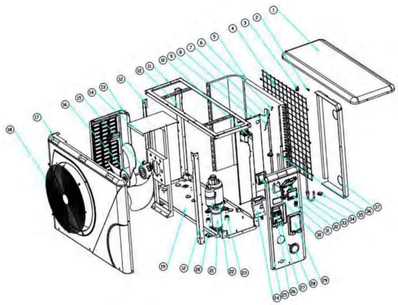
9. Exploded Diagram
Model: ELYO SMART NN 16
text_image
Exploded view diagram of an air conditioning unit with numbered components for identification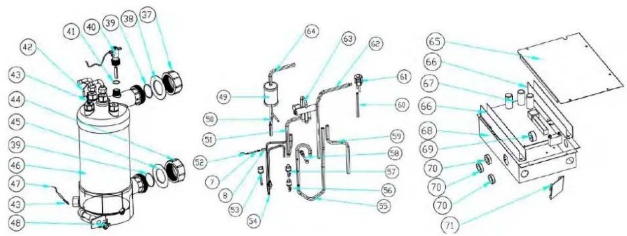
text_image
Technical diagram of a mechanical device with numbered components and exploded view, likely for assembly or manufacturing purposes.9. Exploded Diagram
Model: ELYO SMART NN 16
| NO. | Parts name | 68772 | NO. | Parts name | 68772 |
| 1 | Top cover | 133090029 | 37 | Water connection sets | 113900082 |
| 2 | Ambient temp. sensor TH1 | 117110020 | 38 | Red rubber ring | 133020012 |
| 3 | Ambient temp. sensor clip | 133020010 | 39 | Rubber ring on water connection | 133020026 |
| 4 | Back grill | 108110040 | 40 | Water flow switch | 112100021-1 |
| 5 | Evaporator | 103000130 | 41 | Sealing ring | 116000001-2 |
| 6 | Pipe temp. sensor TH2 | 117110004 | 42 | Water out temp. sensor TH5 | 117110011 |
| 7 | Temperature sensor piping clip | 113190001 | 43 | Exchanger temperature sensor clip | 108010025 |
| 8 | Temperature sensor casing pipe | 44 | Water connection sets | 113900082 | |
| 9 | Isolation panel | 108050073 | 45 | Blue rubber ring | 133020011 |
| 10 | Reactor | 117230003 | 46 | Titanium heat exchanger | 102040549 |
| 11 | Pillar | 108110004 | 47 | Water in temp. sensor TH6 | 117110012 |
| 12 | Top frame | 108110038 | 48 | Drainage plug | 150000110 |
| 13 | Left side panel | 133090026 | 49 | Filter | 120000066 |
| 14 | Fan motor bracket | 108110043 | 50 | Filter to liquid storage tank | 113130002 |
| 15 | Fan motor | 112000031 | 51 | 4 way valve to exchanger | 113030081 |
| 16 | Fan blade | 132000015 | 52 | Exhaust temp. sensor TH3 | 117110021 |
| 17 | Front panel | 133090025 | 53 | High pressure switch | 116000066 |
| 18 | Front grill | 108110012 | 54 | Exhaust piping | 113010159 |
| 19 | Base tray | 108110042 | 55 | Gas return piping | 113020246 |
| 20 | Compressor damping feet | 136020019 | 56 | Low pressure switch | 116000072 |
| 21 | Compressor | 101000162 | 57 | Low pressure switch | 116000071 |
| 22 | Liquid storage tank | 105000004 | 58 | Suction valve | 120000026 |
| 23 | Compressor heating belt | 142000074 | 59 | 4-way valve to collective pipe | 113060084 |
| 24 | Terminal box | 108010065 | 60 | EEV to distribution pipe | 113080051 |
| 25 | Right side panel | 133090028 | 61 | EEV | 119000017 |
| 26 | Pressure gauge | 110800001 | 62 | Liquid storage tank to EEV | 113120002 |
| 27 | 5-bit terminal | 115000004 | 63 | 4 way valve | 121000006 |
| 28 | Clip | 136010004 | 64 | Exchanger to filter | 113170021 |
| 29 | Terminal blocks plastic cover | 133250005 | 65 | Electric box cover | 108050017 |
| 30 | Connector of cable | 110000008 | 66 | Wiring trunking | 136020003 |
| 31 | Wiring box | 108010018 | 67 | Inverter PCB | 117100016-V1.5 |
| 32 | Waterproof controller box | 113712007 | 68 | Electric box | 108110031 |
| 33 | Controller | 117020150 | 69 | magnet ring | 117240002 |
| 34 | Collective assembly | 113050093 | 70 | magnet ring | 117240003 |
| 35 | Distributor assembly | 113040092 | 71 | Modbus module | 117010095 |
| 36 | Back Panel | 133090027 | |||
Model: ELYO SMART NN 20
text_image
Exploded view diagram of an air conditioning unit with numbered components for identification
text_image
Technical diagram of a mechanical device with numbered components and exploded view, likely for assembly or manufacturing purposes.9. Exploded Diagram
Model: ELYO SMART NN 20
| NO | Parts name | 68774 | NO | Parts name | 68774 |
| 1 | Top cover | 133260001 | 37 | Back Panel | 133260002 |
| 2 | Ambient temp. sensor TH1 | 117110020 | 38 | EEV | 119000021 |
| 3 | Ambient temp. sensor clip | 133020010 | 39 | Liquid storage tank to EEV | 113120019 |
| 4 | Back grill | 108560014 | 40 | Exchanger to filte | 113170032 |
| 5 | Evaporator | 103000204 | 41 | 4 way valve | 121000009 |
| 6 | Temperature sensor piping clip | 113190001 | 42 | Exchanger to filter | 113010171 |
| 7 | Temperature sensor casing pipe | 43 | Exhaust temperature sensor TH3 | 117110021 | |
| 8 | Pipe temp. sensor TH2 | 117110004 | 44 | High pressure switch | 116000068 |
| 9 | Isolation panel | 108560010 | 45 | Suction valve | 120000026 |
| 10 | Reactor | 117230002 | 46 | Gas return piping | 113020259 |
| 11 | Top frame | 108560002 | 47 | Low pressure switch | 116000074 |
| 12 | Pillar | 108560003 | 48 | Low pressure switch | 116000073 |
| 13 | Left side panel | 133260005 | 49 | Filter to liquid storage tank | 113130002 |
| 14 | Fan motor bracket | 108560011 | 50 | 4 way valve to collective pipe | 113060096 |
| 15 | Fan motor | 112000031 | 51 | Liquid storage tank | 105000004 |
| 16 | Fan blade | 132000023 | 52 | 4 way valve to exchanger | 113030093 |
| 17 | Front panel | 133260003 | 53 | EEV to distribution pipe | 113080056 |
| 18 | Front grill | 1081700171 | 54 | Water connection sets | 113900082 |
| 19 | Base tray | 108560009 | 55 | Red rubber ring | 133020012 |
| 20 | Compressor | 101000150 | 56 | Rubber ring on water connection | 133020026 |
| 21 | Liquid storage tank | 105000004 | 57 | Water flow switch | 112100021-1 |
| 22 | Compressor heating belt | 142000076 | 58 | Sealing ring | 116000001-2 |
| 23 | Compressor damping feet | 142000076 | 59 | Water out temp. sensor TH5 | 117110011 |
| 24 | Terminal box | 108010065 | 60 | Exchanger temperature sensor clip | 108010025 |
| 25 | Right side panel | 133260004 | 61 | Titanium heat exchanger | 102040555 |
| 26 | 5-bit terminal | 115000004 | 62 | Water connection sets | 113900082 |
| 27 | Clip | 136010004 | 63 | Blue rubber ring | 133020011 |
| 28 | Pressure gauge | 110800001 | 64 | Water in temp. sensor TH6 | 117110012 |
| 29 | Terminal blocks plastic cover | 133250005 | 65 | Drainage plug | 150000110 |
| 30 | Wiring box | 108010018 | 66 | Electric box cover | 108540006 |
| 31 | Connector of cable | 110000008 | 67 | Wiring trunking | 136020003 |
| 32 | Controller | 117020150 | 68 | Inverter PCB | 117100015-V1.5 |
| 33 | Waterproof controller box | 113712007 | 69 | Electric box | 108560012 |
| 34 | Distributor assembly | 113040094 | 70 | magnet ring | 117240002 |
| 35 | B Type Rubber fixing block | 136020005 | 71 | magnet ring | 117240003 |
| 36 | Collective assembly | 113050095 | 72 | Modbus module | 117010095 |
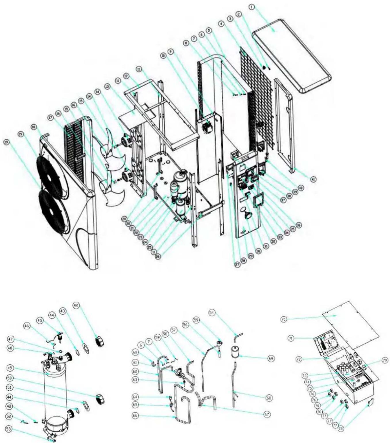
9. Exploded Diagram
Model: ELYO SMART NN 25/25T/30/30T
9. Exploded Diagram
Model: ELYO SMART NN 25/30
| NO | Parts name | 68775 | 68850 | NO | Parts name | 68775 | 68850 |
| 1 | Top cover | 1331000011 | 41 | Back Panel | 133250023 | ||
| 2 | Ambient temp. sensor TH1 | 117110020 | 42 | Water connection sets | 113900082 | ||
| 3 | Ambient temp. sensor clip | 133020010 | 43 | Red rubber ring | 133020012 | ||
| 4 | Back grill | 108550007 | 44 | Rubber ring on water | 133020026 | ||
| 5 | Evaporator | 103000207/103000208 | 45 | Water flow switch | 112100021-1 | ||
| 6 | Temperature sensor piping cl | 113190001 | 46 | Water out temp. sensor TH5 | 117110011 | ||
| 7 | Temperature sensor casing | 113190001 | 47 | Sealing ring | 116000001-2 | ||
| 8 | Pipe temp. sensor TH2 | 117110004 | 48 | Exchanger temperature sensor | 108010025 | ||
| 9 | Isolation panel | 108120036 | 49 | Titanium heat exchanger | 102040503 | ||
| 10 | Reactor | 117230001 | 50 | Water connection sets | 113900082 | ||
| 11 | Pillar | 108120035 | 51 | Blue rubber ring | 133020011 | ||
| 12 | Top frame | 108120034 | 52 | Water in temp. sensor TH6 | 117110012 | ||
| 13 | Fan motor bracket | 108120037 | 53 | Drainage plug | 150000110 | ||
| 14 | Fan motor | 112000031 | 54 | Exchanger to filter | 113170028 | ||
| 15 | Fan motor cover | 108010024 | 55 | EEV | 119000022 | ||
| 16 | Fan blade | 132000015 | 56 | EEV to distribution pipe | 113080055 | ||
| 17 | Left side panel | 133250024 | 57 | Liquid storage tank to EEV | 113120020 | ||
| 18 | Front panel | 1332500011 | 58 | 4 way valve to exchanger | 113030087 | ||
| 19 | Front grill | 108010014 | 59 | Exhaust temperature sensor | 117110021 | ||
| 20 | Pillar | 108550009 | 60 | High pressure switch | 116000068 | ||
| 21 | Base tray | 108550005 | 61 | 4-way valve | 121000009 | ||
| 22 | Compressor | 101000122 | 62 | Exhaust pipe | 113010158 | ||
| 23 | Rubber block | 136020005 | 63 | Suction valve | 120000023 | ||
| 24 | Compressor heating belt | 142000077 | 64 | Low pressure switch | 116000074 | ||
| 25 | Liquid storage tank | 105000008 | 65 | Low pressure switch | 116000073 | ||
| 26 | Pillar | 108550006 | 66 | Gas return piping | 113020245 | ||
| 27 | Terminal box | 108010065 | 67 | 4 way valve to collective pip | 113060083 | ||
| 28 | Connector of cable | 110000008 | 68 | Filter to liquid storage tank | 113130015 | ||
| 29 | Right side panel | 133250022 | 69 | Filter | 120000066 | ||
| 30 | Pressure gauge | 110800001 | 70 | Electric box cover | 108120040 | ||
| 31 | 3-bit terminal for Eletricity | 115000025 | 71 | Driver board | 117140002 | ||
| 32 | Clip | 136010004 | 72 | Electric box | 108120038 | ||
| 33 | Terminal blocks plastic cover | 1332500053 | 73 | Scale board | 108120039 | ||
| 34 | Terminal pillar | 108550006 | 74 | Filter board | 117260001 | ||
| 35 | 3-bit terminal for water pum | 115000027 | 75 | PCB | 117250001-V1.5 | ||
| 36 | Waterproof controller box | 113712007 | 76 | magnet ring | 117240002 | ||
| 37 | Controller | 117020150 | 77 | magnet ring | 117240003 | ||
| 38 | Wiring box | 108010018 | 78 | Modbus module | 117010095 | ||
| 39 | Distribution assembly | 113040101 | 79 | Relay | 142000038 | ||
| 40 | Collective assembly | 113050109 | |||||
9. Exploded Diagram
Model: ELYO SMART NN 25T/30T
| NO | Parts name | 68776 | 68851 | NO | Parts name | 68776 | 68851 |
| 1 | Top cover | 1331000011 | 41 | Back Panel | 133250023 | ||
| 2 | Ambient temp. sensor TH1 | 117110020 | 42 | Water connection sets | 113900082 | ||
| 3 | Ambient temp. sensor clip | 133020010 | 43 | Red rubber ring | 133020012 | ||
| 4 | Back grill | 108550007 | 44 | Rubber ring on water | 133020026 | ||
| 5 | Evaporator | 103000207/103000208 | 45 | Water flow switch | 112100021-1 | ||
| 6 | Temperature sensor piping | 113190001 | 46 | Water out temp. sensor TH5 | 117110011 | ||
| 7 | Temperature sensor casing | 113190001 | 47 | Sealing ring | 116000001-2 | ||
| 8 | Pipe temp. sensor TH2 | 117110004 | 48 | Exchanger temperature | 108010025 | ||
| 9 | Isolation panel | 108120036 | 49 | Titanium heat exchanger | 102040503 | ||
| 10 | Reactor | 117230001 | 50 | Water connection sets | 113900082 | ||
| 11 | Pillar | 108120035 | 51 | Blue rubber ring | 133020011 | ||
| 12 | Top frame | 108120034 | 52 | Water in temp. sensor TH6 | 117110012 | ||
| 13 | Fan motor bracket | 108120037 | 53 | Drainage plug | 150000110 | ||
| 14 | Fan motor | 112000031 | 54 | Exchanger to filter | 113170028 | ||
| 15 | Fan motor pipe cover | 108010024 | 55 | EEV | 119000022 | ||
| 16 | Fan blade | 132000015 | 56 | EEV to distribution pipe | 113080055 | ||
| 17 | Left side panel | 133250024 | 57 | Liquid storage tank to EEV | 113120020 | ||
| 18 | Front panel | 1332500011 | 58 | 4 way valve to exchanger | 113030087 | ||
| 19 | Front grill | 108010014 | 59 | Exhaust temperature sensor | 117110021 | ||
| 20 | Panel pillar | 108550009 | 60 | High pressure switch | 116000068 | ||
| 21 | Base tray | 108550005 | 61 | 4-way valve | 121000009 | ||
| 22 | Compressor | 101000122 | 62 | Exhaust pipe | 113010158 | ||
| 23 | Rubber block | 136020005 | 63 | Suction valve | 120000023 | ||
| 24 | Compressor heating belt | 142000077 | 64 | Low pressure switch | 116000074 | ||
| 25 | Liquid storage tank | 105000008 | 65 | Low pressure switch | 116000073 | ||
| 26 | Pillar | 108550006 | 66 | Gas return piping | 113020245 | ||
| 27 | Terminal box | 108010065 | 67 | 4 way valve to collective pip | 113060083 | ||
| 28 | Connector of cable | 110000008 | 68 | Filter to liquid storage tank | 113130015 | ||
| 29 | Right side panel | 133250022 | 69 | Filter | 120000066 | ||
| 30 | Pressure gauge | 110800001 | 70 | Electric box cover | 108120040 | ||
| 31 | 3-bit terminal for Eletricity | 115000025 | 71 | Driver board | 117140003 | ||
| 32 | Clip | 136010004 | 72 | Electric box | 108120038 | ||
| 33 | Terminal blocks plastic cover | 1332500053 | 73 | Scale board | 108120039 | ||
| 34 | Terminal pillar | 108550006 | 74 | Filter board | 117260002 | ||
| 35 | 3-bit terminal for water pun | 115000027 | 75 | PCB | 117250001-V1.5 | ||
| 36 | Waterproof controller box | 113712007 | 76 | magnet ring | 117240002 | ||
| 37 | Controller | 117020150 | 77 | magnet ring | 117240003 | ||
| 38 | Wiring box | 108010018 | 78 | Modbus module | 117010095 | ||
| 39 | Distribution assembly | 113040101 | 79 | Relay | 142000038 | ||
| 40 | Collective assembly | 113050109 | |||||
9. Exploded Diagram
9.3 Maintenance
(1) You should check the water supply system regularly to avoid the air entering the system and occurrence of low water flow, because it would reduce the performance and reliability of HP unit.
(2) Clean your pools and filtration system regularly to avoid the damage of the unit as a result of the dirty of clogged filter.
(3) You should discharge the water from bottom of water pump if HP unit will stop running for a long time (especially during the winter season).
(4) In another way, you should check the unit is water fully before the unit start to run again.
(5) After the unit is conditioned for the winter season, it is recommended to cover the heat pump with special winter heat pump.
(6) When the unit is running, there is all the time a little water discharge under the unit.
natural_image
Technical line drawing of a fan or vent system with dimension annotations (716 and 19) — no readable text or symbols beyond measurement lines.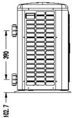
text_image
390 102.7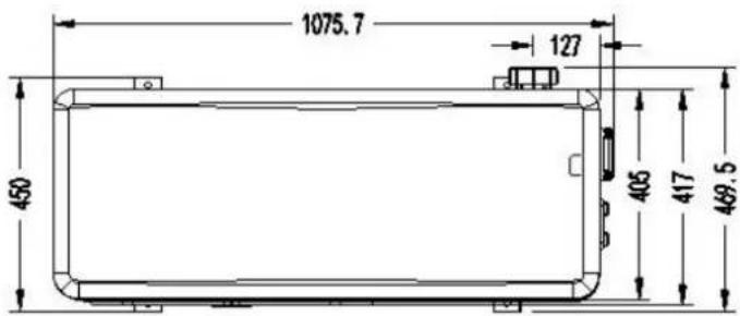
text_image
1075.7 127 450 405 417 469.5natural_image
Technical line drawing of a fan or vent system with dimension annotations (880.5 and 26) — no readable text or symbols beyond measurement labels.
natural_image
Technical line drawing of a door with checkered pattern and dimension annotations (no text or symbols)
text_image
1145, 2 141 444 416 424, 7 477, 31. Descriptif
Modèles : Elyo Smart NN 25 / 25T /30 /30T

text_image
1291,5 25 1076 125,7 452 311 422,7 472,6
text_image
80.0 86.52. Conditions de transport
natural_image
Illustration of a delivery truck and a cardboard box with a pallet jack (no text or symbols)natural_image
Close-up of a black conical object with a metallic bolt and hexagonal nut, resting on a wooden surface (no text or symbols visible)Patin caoutchouc anti-vibration, qté
natural_image
Close-up of a black plastic electronic component with a rectangular cutout and mounting holes (no visible text or symbols)natural_image
Two types of wire or cable components: a white cord with wires and a black coiled wire (no text or symbols visible)natural_image
Two white plastic pipe fittings, one closed and one threaded (no text or symbols visible)natural_image
White powder bag wrapped in plastic wrap, no visible text or symbolsnatural_image
3D rendering of a white and red pipe fitting with two flanges (no text or symbols visible)4. Accessoires et options
text_image
Reactor Magnet ring (WHT) FAN RED 11 12 Magnet ring (WHT) FAN2 OUT9 ON WOC 4-Way valve coil N6 N5 N4 OUT6 OUT5 OUT4 Base Electric heater Crankshaft electric heating N3 N2 N1 N9 OUT3 OUT2 OUT1 EEPROM Burning interface W V U Magnet ring (BLK) RED BLK WHT JTAG Electronic Expansion Valve Ambient temperature Coil Temperature Exhaust Temperature Water out temperature Water in temperature T11 TH2 TH3 TH4 TH5 TH6 TH7 TH8 COM1 COM2 NO OUT10 NO 1 2 AC-N AC-L TS1 TS2 TS3 TS4 TS5 Defrosting switch High pressure switch Low pressure switch Magnet ring (BLK) BRN A+B-GND; Modbus Signallines * The dotted line part are only used in some models I-3041 220V~50Hz Switchtext_image
Reactor Magnet ring (WHT) FAN RED I1 I2 Magnet ring (WHT) FAN2 OUT9 NO MOD 4-Way valve coil N6 N5 N4 OUT6 OUT5 OUT4 Base Electric heater Crankshaft electric heating N3 N2 N1 N9 OUT3 OUT2 OUT1 EEPROM Burning interface COM NO OUT10 NO 1/2 PE AC-N AC-L W V U Magnet ring (BLK) RED BLK WHT JTAG TH1 TH2 TH3 TH4 TH5 TH6 TH7 TH8 Electronic Expansion Valve Ambient temperature Coil Temperature Exhaust Temperature Water out temperature Water in temperature Water in temperature Water flow switch Defrosting switch High pressure switch Low pressure switch Magnet ring (BLK) Short catch PCB TS3: Select DC fan Disconnect PCB TS3: Select AC fan Controller Modbus L N 1 2 220V~50Hz Switch (PUMP) COMPRESSOR I-3041M * The dotted line part are only used in some modelstext_image
Fan DC #1 Fan DC #2 (WHT Magnet ring CN1 CN51 CN607 C14 CN14 CN14 CN14 CN14 CN14 CN14 CN14 CN14 CN14 CN14 CN14 CN14 CN14 CN14 CN14 CN14 CN14 CN14 CN14 CN14 CN14 CN14 CN14 CN14 CN14 CN14 CN14 CN14 CN14 CN14 CN14 CN14 CN14 CN C12 T1 K21 SW SHQ050101 C46 C116 C120 C119 G L I1 N I2 DC-DC-U V W P Magnet ring (BLK) RED RED BLK WHT COMPRESSOR PE Reactor I-5101M 4 line Water flow switch Defrosting switch High pressure switch Low pressure switch Base Electric heater 4-Way valve coil Crankshaft electric heating RED BLU Electric heating of water tank NC NO COM 1 2 3 4 5 6 7 8 9 Switch Magnet ring (WHT) BRN BLU BLU PE C8 N' C4 TVS1 N C39 C38 L1 L-OUT R1 L-OUT T2 C17 C14 R2 FU2 FU1 L DC+ BC DC HMF-1W-1 1500100 0 1 2 3 4 5 6 7 8 9 SHZKA0101 SHZKA0101 Water in temperature. Water out temperature. Exhaust Temperature Coil Temperature Ambient temperature COOL/VFL CN2 CN4 ON6 OSM/LOCM/LOCM/D Wire controller Electronic expansion valve 220V~50Hz * The dotted line part are only used in some modelstext_image
Water in temperature Water out temperature Exhaust Temperature Coil Temperature Ambient temperature Water flow switch Low pressure switch High pressure switch Deferring switch Water flow switch LOW pressure switch SHZKA0101 SHQ05T0101 Magnet ring (BLK) COMPRESSOR Magnet ring (BLK) R S T I I DC-12 DC+ U V W R S T I I DC-12 DC+ U V W R S T I I DC-12 DC+ U V W R S T I I DC-12 DC+ U V W R S T I I DC-12 DC+ U V W R S T I I DC-12 DC+ U V W R S T I I DC-12 DC+ U V W R S T I I DC-12DC+ U V W R S T I I DC-12 DC+ U V W R S T I I DC-12 DC+ U V W R S T I I DC-12 DC+ U V W R S T I I DC-12 DC+ U V W R S T I I DC-12 DC+ U V W R S T I I DC-12 DC+ U V W R S T I II DC-12 DC+ U V W R S T I II DC-12 DC+ U V W R S T I II DC-12 DC+ U V W R S T I II DC-12 DC+ U V W R S T I II DC-12 DC+ U V W R S T I II DC-12 DC+ U V W R S T I II DC-12 DC+ U V W * The dotted line part are only used in some models I-531text_image
I-531M * The dotted line part are only used in some models SHQ05T0101 R S T I1 DC-I2 DC+ U V W Magnet ring (BLK) Reactor COMPRESSOR PE T' T1' S' S1' R' N' N1' BLU DC- RED DC+ T1' S1' R1' N1' BLU GND PE FAN 1 DC 5 FAN 2 DC 5 Magnet ring (WHT) 4 line Water flow switch Deirising switch High pressure switch Low pressure switch Base Electric heater 4-Way valve coil Crankshaft electric heating RED BLU Electric heating of water tank RED PE PUMP SWITCH RED A B C N PE 380-415V 3N-50Hz SHZKA0101 Magnet ring (WHT) 4 line Water in temperature Water out temperature Exhaust Temperature Coil Temperature Ambient temperature COM WIFI CN3 CN4 CN26 COM LOOM J CON D Wire controller 5 line Electronic expansion valvenatural_image
Interior view of an electrical enclosure showing wiring and components (no visible text or symbols)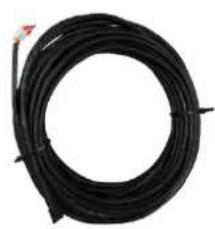
natural_image
Coiled black cable or wire with a small red mark at the top (no text or symbols visible)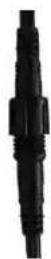
natural_image
Three colored electrical connectors with labels (A+, GND, B-) on a wooden surface (no readable text or symbols beyond labels)text_image
Heat Cool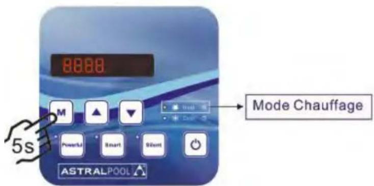
text_image
8888 Mode Chauffage 5s M Powerful Smart 90mm ASTRALPOOL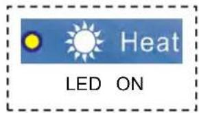
text_image
Heat LED ONtext_image
Technical diagram of an air conditioning unit with numbered components for identification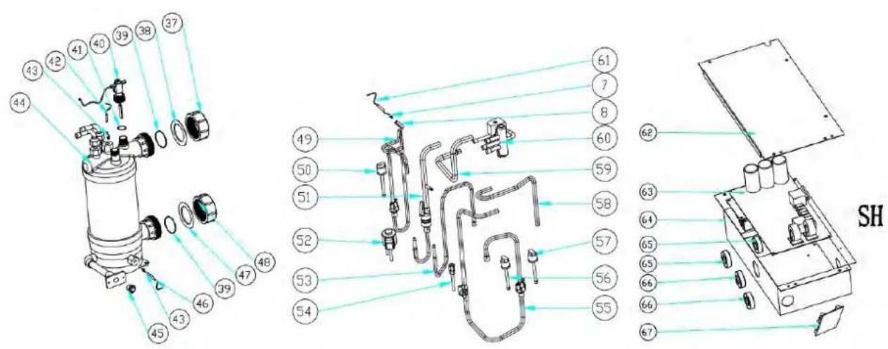
text_image
Technical diagram of a mechanical device with numbered components and labeled parts, including a zoomed-in view of the internal structure.text_image
Exploded view diagram of an air conditioning unit with numbered components for identification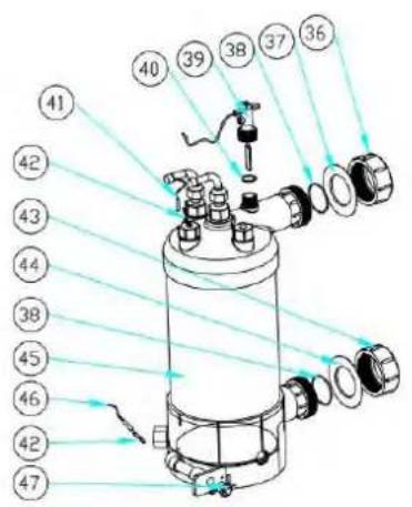
text_image
Technical diagram of a cylindrical device with numbered components and light rays indicating light paths or measurement lines.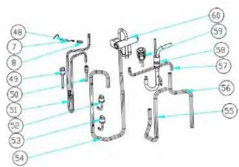
text_image
48 7 8 49 50 51 52 53 54 60 59 58 57 56 55
text_image
Technical diagram of a device with numbered components and directional arrows indicating assembly or movement.text_image
Exploded view diagram of an air conditioning unit with numbered components for identification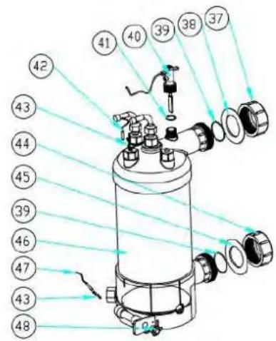
text_image
Technical diagram of a cylindrical mechanical device with numbered components and light ray paths indicating flow or alignment.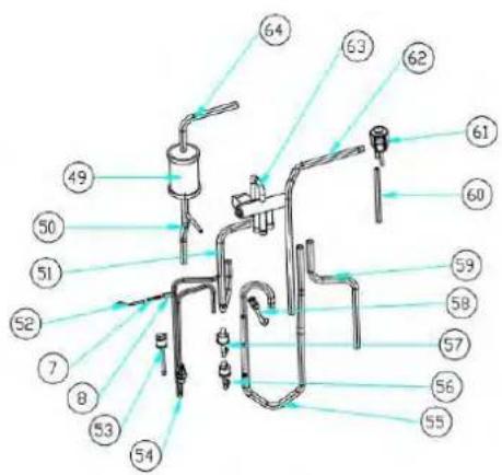
text_image
Labeled diagram of a laboratory apparatus with numbered components for identification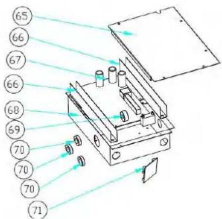
text_image
Technical diagram of an optical or mechanical device with numbered components and light paths indicated by arrows.text_image
Exploded view diagram of an air conditioning unit with numbered components for identification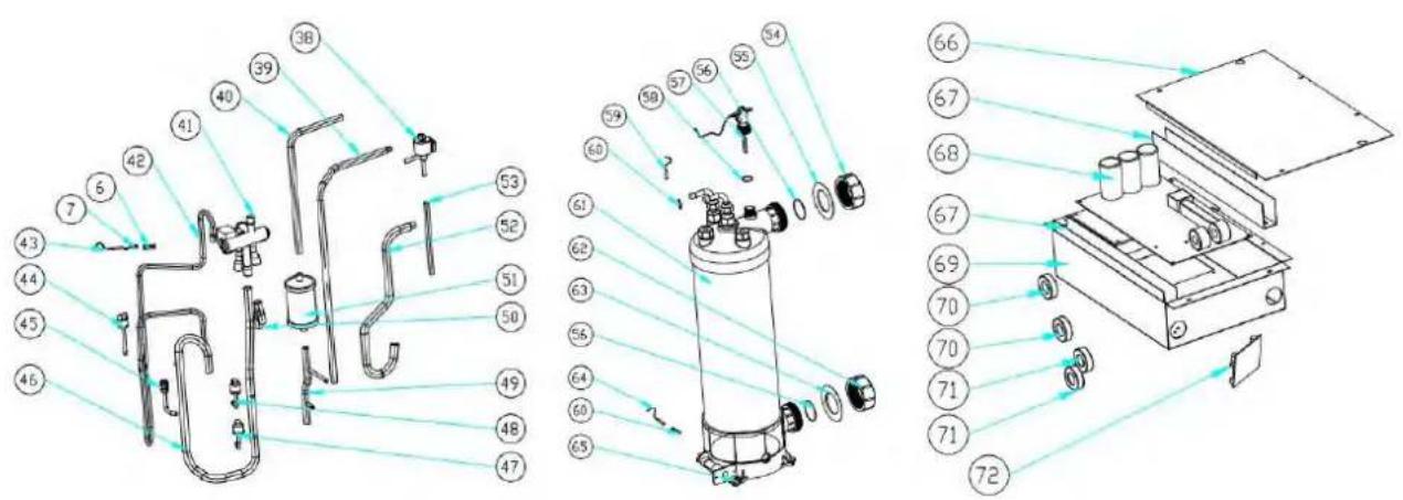
text_image
Technical diagram of a mechanical device with numbered components and exploded view, likely for assembly or manufacturing purposes.natural_image
Technical line drawing of a fan or air conditioning unit with dimension annotations (716 and 19) — no readable text or symbols beyond measurement lines.
text_image
390 102.7
text_image
1075.7 127 450 405 417 469.5Model: ELYO SMART NN 20

natural_image
Technical line drawing of a fan or air conditioning unit with dimension annotations (no text labels or symbols)
text_image
600 111.5
text_image
1145, 2 141 444 416 424, 7 477, 31. Afmetingen
Model: ELYO SMART NN 25/25T, ELYO SMART NN 30/30T

text_image
1291.5 25 1076 125.7 452 311 422.7 472.6
text_image
800 86.52. Transport en opslag
2.1 Transport

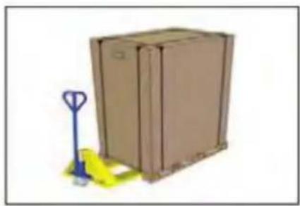
natural_image
Illustration of a brown cardboard box with a blue pallet jack beside it, no text or symbols present.natural_image
Close-up of a black conical object with a metallic bolt and cap, resting on a wooden surface (no text or symbols visible)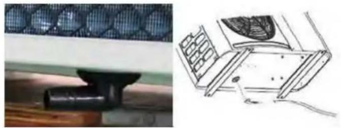
natural_image
Technical illustration of a mechanical component with a mesh pattern and its 3D schematic view (no text or symbols)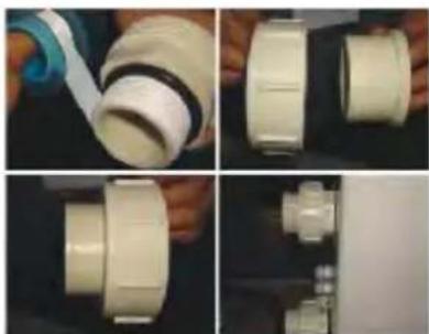
natural_image
Four-panel photo showing hands assembling a white plastic pipe fitting, with no visible text or symbols.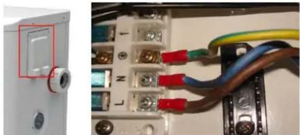
natural_image
Close-up of an electrical circuit board with wires and connectors, no visible text or symbols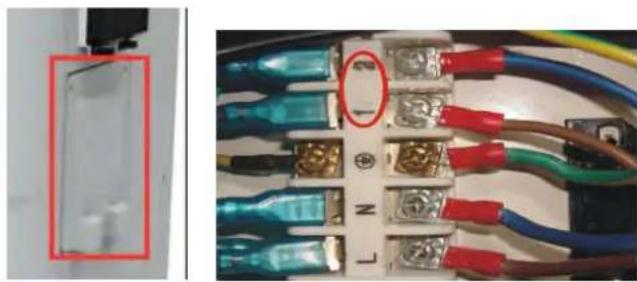
natural_image
Close-up of a circuit board with blue and red wires, no visible text or symbolsAnti-vibratie rubbers
text_image
Reactor Magnet ring (WHT) FAN RED 11 12 Magnet ring (WHT) FAN2 OUT9 NO MOC 4-Way valve vol N6 N5 N4 OUT6 OUT5 OUT4 Base Electric heater Crankshaft electric heating N3 N2 N1 N9 OUT3 OUT2 OUT1 EEPROM Burning interface NO COM OUT10 1 2 PE AC-N AC-L COM1 COM2 TH1 TH2 TH3 TH4 TH5 TH6 TH7 TH8 TH1 TH2 TH3 TH4 TH5 TH6 TH7 TH8 Ambient temperature Coil Temperature Exhaust Temperature Water out temperature Water in temperature Wire controller Modbus Signal lines Defrosting switch High pressure switch Low pressure switch Magnet ring (BLK) BRN BLU RED L N 1 2 COMPRESSOR JTAG Electronic Expansion Valve * The dotted line part are only used in some models I-3041 220V~50Hz Switchtext_image
Fan DC #1 Fan DC #2 5 line 5 line (WHT Magnet ring CN14 CN17 CN20 CN31 CN32 CN38 CN41 C12 T1 C5 C6 K21 SW SHQ050101 C46 C116 C120 C119 G L I1 N I2 DC-DC+ U V W P Magnet ring (BLK) RED RED Magnet ring (BLK) COMPRESSOR PE Reactor I-5101 4 line Water flow switch Defrosting switch High pressure switch Low pressure switch FLS 4-Way valve coil Crankshaft electric heating RED BLU Electric heating of water tank Switch Magnet ring (WHT) BRN BLU PE T/S1 N C38 N' C39 C4 L-OUT R1 L-OUT L- T2 C17 C14 R2 FL2 FU1 DC- BLU DC-HMF1W-1 1909105 0 1 2 3 4 5 6 7 8 9 SHZKA0101 WATER IN TEMPERATURE WATER OUT TEMPERATURE EXHAUST TEMPERATURE COIL TEMPERATURE AMBIENT TEMPERATURE COM/WFI CN3 CN4 CONS COM LOOM LOOM D SHZKA0101 4 line 5 line Wire controller Electronic expansion valve Magnet ring (BLK) BLU BRN * The dotted line part are only used in some modelstext_image
Fan DC #1 Fan DC #2 WHT Magnet ring CN14 CN14 CN14 CN14 CN14 CN14 CN14 CN14 CN14 CN14 CN14 CN14 CN14 CN14 CN14 CN14 CN14 CN14 CN14 CN14 CN14 CN14 CN14 CN14 CN14 CN14 CN14 CN14 CN14 CN14 CN14 CN14 CN14 CN14 SNV C12 T1 K21 SW C5 CS8 S7 P SHQ050101 C46 C116 C120 C119 G L I1 N I2 Magnet ring (BLK) RED RED RBC DC DC U V W P Magnet ring (BLK) COMPRESSOR PE BLU BLU BRN L OUT BRN T2 C17 C14 R2 FLU FU1 DC+ RED BLU DC HMF1W-1 150/305 I-5101M 4 line Water flow switch Defraining switch High pressure switch Low pressure switch FLS 3) TOOL0 GRESET Base Electric heater 4-Way valve coil Crankshaft electric heating RED BLU Electric heating of water tank RED RED PE Switch Magnet ring (WHT) BRN Power in temperature Water out temperature Exhaust Temperature Coil Temperature Ambient temperature SHZKA0101 4 line Wire controller Electronic expansion valve COM L L N 220V~50Hz COM L LED1 LED2 LED3 LED4 LED5 LED 3.3 3.5 3.7 3.9 Wire controller * The dotted line part are only used in some modelstext_image
Water in temperature Water out temperature Extrast Temperature Coil Temperature Ambient temperature 4 line Water flow switch Low pressure switch High pressure switch Detrusting switch SHZKA0101 SHQ05T0101 R S T 11 DC-12 DC+ U V W COMPRESSOR PE Magnet ring (BLK) Red Reactor Magnet ring (BLK) R1 S1 T1 N1' S' R' N' N' DC+ DC+ * The dotted line part are only used in some models I-531natural_image
Close-up of a blue medical device with buttons and display screen (no visible text or symbols)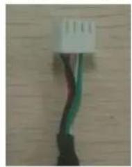
natural_image
Close-up of a white electrical connector with green and black wires against a wooden background (no text or symbols visible)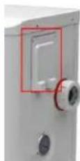
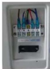
natural_image
Close-up of a white electrical outlet with multiple colored wires and a small black indicator block (no visible text or symbols)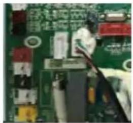
natural_image
Close-up of a green printed circuit board with visible traces and components (no readable text or symbols)natural_image
Interior view of an electrical enclosure showing wiring and components (no visible text or symbols)
natural_image
Coiled black cable or wire with a small red mark at the top (no text or symbols visible)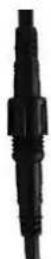
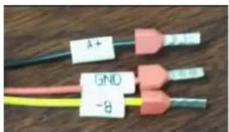
text_image
A+ GND -8text_image
L N Water pomptext_image
Exploded view diagram of an air conditioning unit with numbered components for identification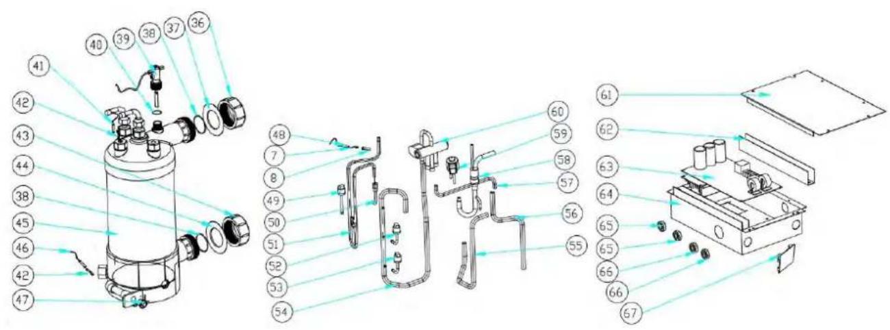
text_image
Exploded view diagram of a mechanical device with numbered components for identification9. Open geklapt diagram
Model: ELYO SMART NN 12
| NO. | Deel naam | 68771 | NO. | Deel naam | 68771 |
| 1 | Bovenklep | 133090029 | 35 | Achterpaneel | 133090027 |
| 2 | Omgevingstemp. sensor TH1 | 117110020 | 36 | Wateraansluitsets | 113900082 |
| 3 | Omgevingstemp. sensor clip | 133020010 | 37 | Rode rubberen ring | 133020012 |
| 4 | Teruggrillen | 108110040 | 38 | Rubberring op wateraansluiting | 133020026 |
| 5 | Verdamper | 103000182 | 39 | Waterstroomschakelaar | 112100021-1 |
| 6 | Pijp temp. sensor TH2 | 117110004 | 40 | Afsluitring | 116000001-2 |
| 7 | Klem voor | 113190001 | 41 | Water uit temp. sensor TH5 | 117110011 |
| 8 | Sensorhuispijp | 42 | Wisselaar sensor | 108010025 | |
| 9 | Isolatiepaneel | 108050073 | 43 | Wateraansluitsets | 113900082 |
| 10 | reactor | 117230003 | 44 | Blauwe rubberen ring | 133020011 |
| 11 | Pijler | 108110004 | 45 | Titanium warmtewisselaar | 102040548 |
| 12 | Bovenframe | 108110038 | 46 | Water in temp. sensor TH6 | 117110012 |
| 13 | Linkerkant paneel | 133090026 | 47 | Drainage plug | 150000110 |
| 14 | Ventilatormotorbeugel | 108110043 | 48 | Uitlaat temp. sensor TH3 | 117110021 |
| 15 | Ventilatormotor | 112000031 | 49 | Hogedrukschakelaar | 116000066 |
| 16 | Waaierblad | 132000015 | 50 | Zuigventiel | 120000026 |
| 17 | Voorpaneel | 133090025 | 51 | Uitlaatleidingen | 113010165 |
| 18 | Voorrooster | 108110012 | 52 | Lagedrukschakelaar | 116000072 |
| 19 | Basislade | 108110042 | 53 | Lagedrukschakelaar | 116000071 |
| 20 | Demping voeten van de | 136020019 | 54 | Gas retourleidingen | 113020252 |
| 21 | Compressor | 101000163 | 55 | 4-wegklep naar wisselaar | 113030081 |
| 22 | Compressor verwarmingsriem | 142000072 | 56 | 4-wegsklep naar collectieve | 113060084 |
| 23 | Vertrekhal bord | 108010065 | 57 | EEV naar distributieleidingen | 113080061 |
| 24 | Rechter zijpaneel | 133090028 | 58 | Uitwisselaar van EEV | 113070037 |
| 25 | Druk meter | 110800001 | 59 | EEV | 119000017 |
| 26 | 5-zits terminal | 115000004 | 60 | 4-weg klep | 121000006 |
| 27 | Klem | 136010004 | 61 | Elektrische deksel | 108050017 |
| 28 | Klemmenblokken plastic kap | 133250005 | 62 | Bedrading trunking | 136020003 |
| 29 | draadverbinding | 110000008 | 63 | Inverter PCB | 117100014-V1.5 |
| 30 | Bedradingsdoos | 108010018 | 64 | Elektrische doos | 108110031 |
| 31 | Waterdichte controllerkast | 113712007 | 65 | magneetring | 117240002 |
| 32 | controleur | 117020150 | 66 | magneetring | 117240003 |
| 33 | Collectieve vergadering | 113050093 | 67 | Modbus-module | 117010095 |
| 34 | Distributeur montage | 113040092 | |||
9. Open geklapt diagram
Model: ELYO SMART NN 16
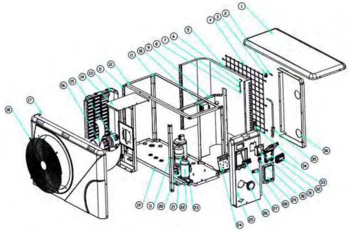
text_image
Exploded view diagram of an air conditioning unit with numbered components for identification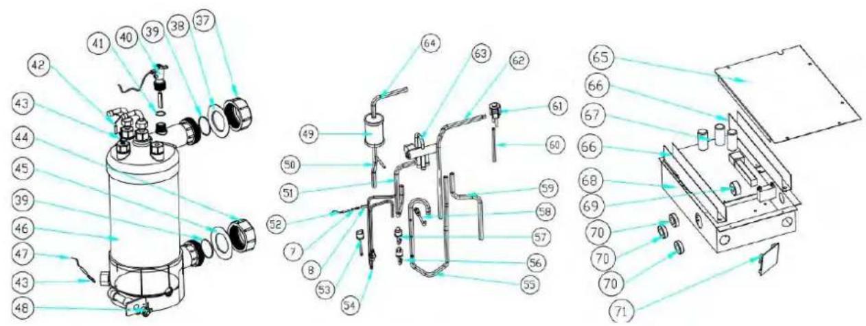
text_image
Technical diagram of a mechanical device with numbered components and exploded view, likely for assembly or manufacturing purposes.9. Open geklapt diagram
Model: ELYO SMART NN 16
text_image
Exploded view diagram of an air conditioning unit with numbered components for identification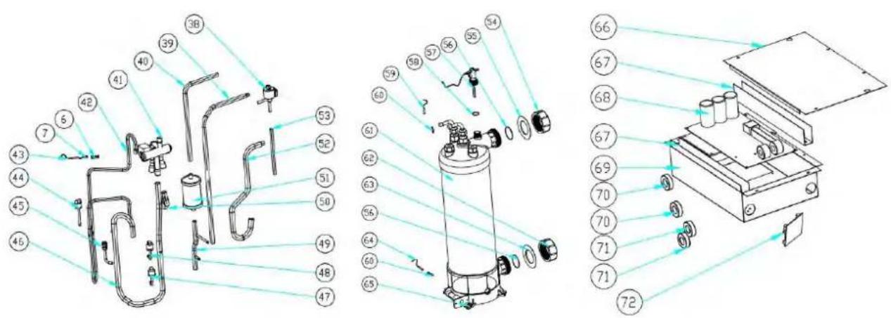
text_image
Technical diagram of a mechanical device with numbered components and exploded view, likely for assembly or manufacturing purposes.9. Open geklapt diagram
Model: ELYO SMART NN 20
text_image
Exploded view diagram of an air conditioning unit with numbered components for identification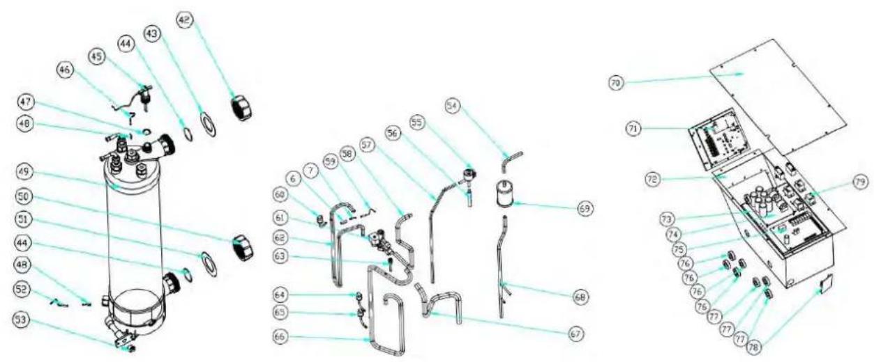
text_image
Exploded view diagram of a mechanical device with numbered parts for identification9. Open geklapt diagram
Model: ELYO SMART NN 25/30
natural_image
Technical line drawing of a rectangular HVAC unit with fan and side panel, showing dimensions 716 and 19 (no text or symbols beyond measurement annotations)
text_image
390 102.7
text_image
1075.7 127 450 405 417 469.5Modelo: ELYO SMART NN 20
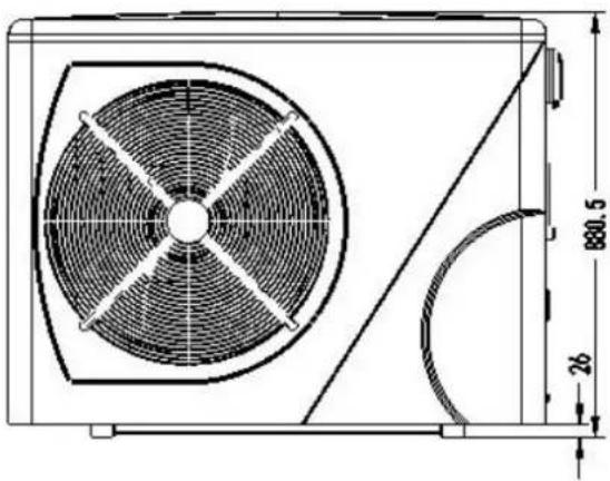
natural_image
Technical line drawing of a fan or air conditioning unit with dimension annotations (880.5 and 26) — no readable text or symbols beyond measurement lines.
text_image
600 111.5
text_image
1145, 2 141 444 416 424, 7 477, 31. Descripción
Modelo : ELYO SMART NN 25/ 25T, ELYO SMART NN 30/ 30T

text_image
1291,5 25 1076 125,7 452 311 422,7 472,6
text_image
80.0 86.5natural_image
Illustration of a brown cardboard box with a blue handle and yellow pallet jack beside it (no text or symbols)natural_image
Close-up of a black conical object with a metallic bolt and hexagonal nut, placed on a wooden surface (no text or symbols visible)Base antivibraciones, 4 pcs
natural_image
Close-up of a black plastic electronic component with no visible text or symbolsCaja impermeable, 1 pc
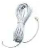
natural_image
Two white plastic pipe fittings, one cylindrical and one flanged, shown against a dark background (no text or symbols visible)natural_image
3D rendering of a white and red U-shaped pipe fitting with flanges (no text or symbols visible)text_image
Heat pump Power cable inlet Outlet Inlet Condensed water draining pipe Draining nozzle Water processor Discharge water pool Side connection valve Pool water inlet Water pump Filter
NOTA
Ref. ELYO SMART NN 06/09/12/16/20
text_image
Reactor Magnet ring (WHT) FAN RED 11 12 Magnet ring (WHT) FAN2 OUT9 N6 N5 N4 N3 N2 N1 N9 OUT6 OUT5 OUT4 Crankshaft electric heating OUT3 OUT2 OUT1 EEPROM Burning interface NO COM OUT10 1 2 PE AC-N AC-L COM1 COM2 TH1 TH2 TH3 TH4 TH5 TH6 TH7 TH8 TH1 TH2 TH3 TH4 TH5 TH6 TH7 TH8 AC- AC- TS1 TS2 TS3 TS4 TS5 Magnet ring (BLK) LED BLK WHT Electronic Expansion Valve Comb Temperature Coil Temperature Exhaust Temperature Water out temperature Water in temperature Wire controller A+B-GND* Modbus Signal lines Defrosting switch High pressure switch Low pressure switch BRN BLU RED L N 1 2 * The dotted line part are only used in some models I-3041 220V~50Hz SwitchRef. ELYO SMART NN 25/30
text_image
Fan DC #1 Fan DC #2 5 line 5 line (WHT Magnet ring CN14 CN14 CN14 CN14 CN14 CN14 CN14 CN14 CN14 CN14 CN14 CN14 CN14 CN14 CN14 CN14 CN14 CN14 CN14 CN14 CN14 CN14 CN14 CN14 CN14 CN14 CN14 CN14 CN14 CN14 CN14 CN14 CN14 CN14 SNV C12 T1 K21 SW C5 C58 C59 C60 C61 C62 C63 C64 C65 C66 C67 C68 C69 C70 C71 C72 C73 C74 C75 C76 C77 C78 C79 SHQ050101 C46 C118 C120 C119 G L I1 N I2 DC DC+ U V W P Magnet ring RED RED BLK Magnet ring (BLK) COMPRESSOR PE BLU BLU BLU N-OUT R1 BRN L-OUT L-OUT DC+ RED BLU T2 C17 C14 R2 FU2 FU1 DC HMFW-1 100H05 I-5101M * The dotted line part are only used in some models Water flow switch Defrosting switch High pressure switch Low pressure switch Base Electric heater 4-Way valve coil Crankshaft electric heating RED BLU Electric heating of water tank Switch Magnet ring (WHT) BRN Magnet ring (BLK) 220V~50Hz Water in temperature Water out temperature Exhaust Temperature Coil Temperature Ambient temperature CDM/FL CN3 DN4 CN2 CN3 CN3 CN3 CN3 CN3 CN3 CN3 CN3 CN3 CN3 CN3 CN3 CN3 CN3 CN3 CN3 CN3 CN3 CN3 CN3 CN3 CN3 CN3 CN3 CN3 CN3 CN3 CN3 CN3 CN3 CN3 CN3 CN3 CN3 CN3 CN3 CN3 CN3 CN3 CN3 CN3 CN3 CN3 CN3 CN3 CN3 CN3 CN3 CN3 CN3 CN 4 line Wire controller Electronic expansion valve Wire controller * The dotted line part are only used in some modelstext_image
Water in temperature Water out temperature Exhaust Temperature Coil Temperature Ambient temperature WIRE temperature Wire controller 5 line Electronic expansion valve SHZKA0101 * The dotted line part are only used in some models I-531 4 line Water flow switch Low pressure switch High pressure switch Detrusting switch Water flow switch Magnet ring WHT) FAN 2 DC FAN 1 DC CNC07 CNC06 CNC05 CNC04 CNC03 CNC02 CNC01 CNC00 CNC01 CNC02 CNC03 CNC04 CNC05 CNC06 CNC07 CNC08 CNC09 CNC10 CNC11 CNC12 CNC13 CNC14 CNC15 CNC16 CNC17 CNC18 CNC19 CNC20 CNC21 R S T 11 DC-12 DC+ U V W R 21 SHQ05T0101 Magnet ring (BLK) COMPRESSOR PE Reactor Magnet ring (BLK) R1 R BLK N N1 T1 T S S1 R BLK N N1 T1 T S S' R R N N1' N' N' S' R N N' DC+ DC+ SHZKA0101 ON2 COIL COM D ON1 COM L COM D ON2 COIL COM D ON3 COM L COM D ON4 COM L COM D ON5 COM L COM D ON6 COM L COM D ON7 COM L COM D ON8 COM L COM D ON9 COM L COM D ON10 COM L COM D ON11 COM L COM D ON12 COM L COM D ON13 COM L COM D ON14 COM L COM D ON15 COM L COM D ON16 COM L COM D ON17 COM L COM D ON18 COM L COM D ON19 COM L COM D ON20 COM L COM D ON21 COM L COM Dnatural_image
Close-up of a blue electronic device with control buttons and a display screen (no visible text or symbols)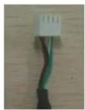
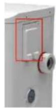
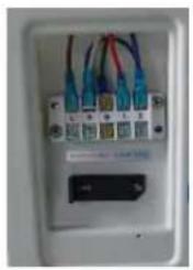
natural_image
Close-up of a white electronic device front panel with multiple colored wires and connectors (no visible text or symbols)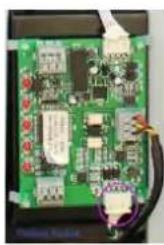
natural_image
Close-up of a green printed circuit board with visible traces and components (no readable text or symbols)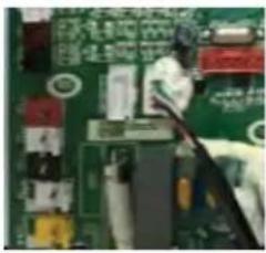
natural_image
Close-up of a green printed circuit board with visible traces and components (no readable text or symbols)natural_image
Interior view of an electrical enclosure showing wiring and components (no visible text or symbols)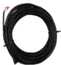
natural_image
Coiled black cable or wire with a small red connector at the top (no text or symbols visible)

text_image
A+ GND -8text_image
Technical diagram of an air conditioning unit with numbered components and exploded view, showing internal structure and assembly.text_image
Exploded view diagram of an air conditioning unit with numbered components for identification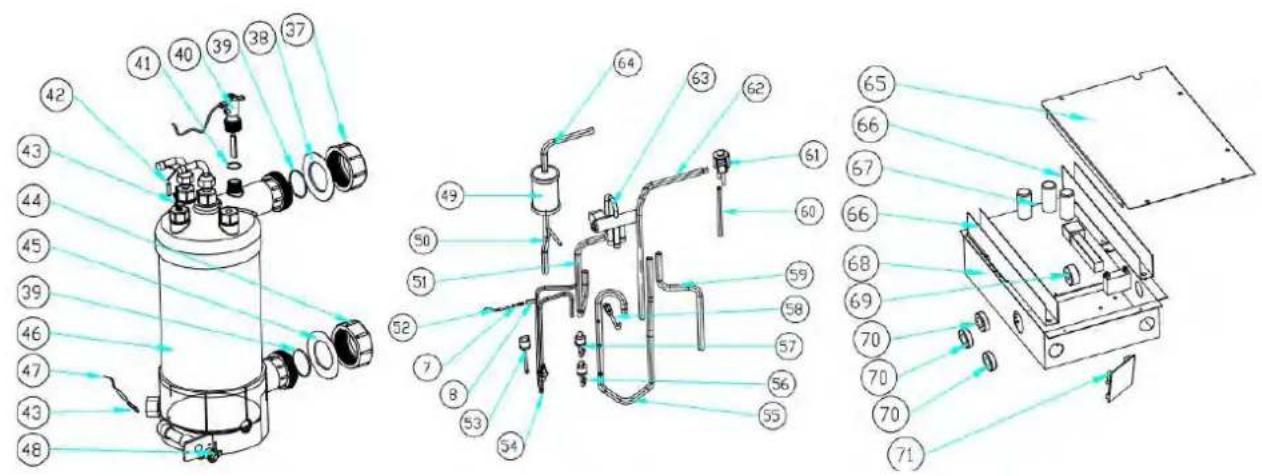
text_image
Technical diagram of a mechanical device with numbered components and exploded view, likely for assembly or manufacturing purposes.text_image
Exploded view diagram of an air conditioning unit with numbered components for identification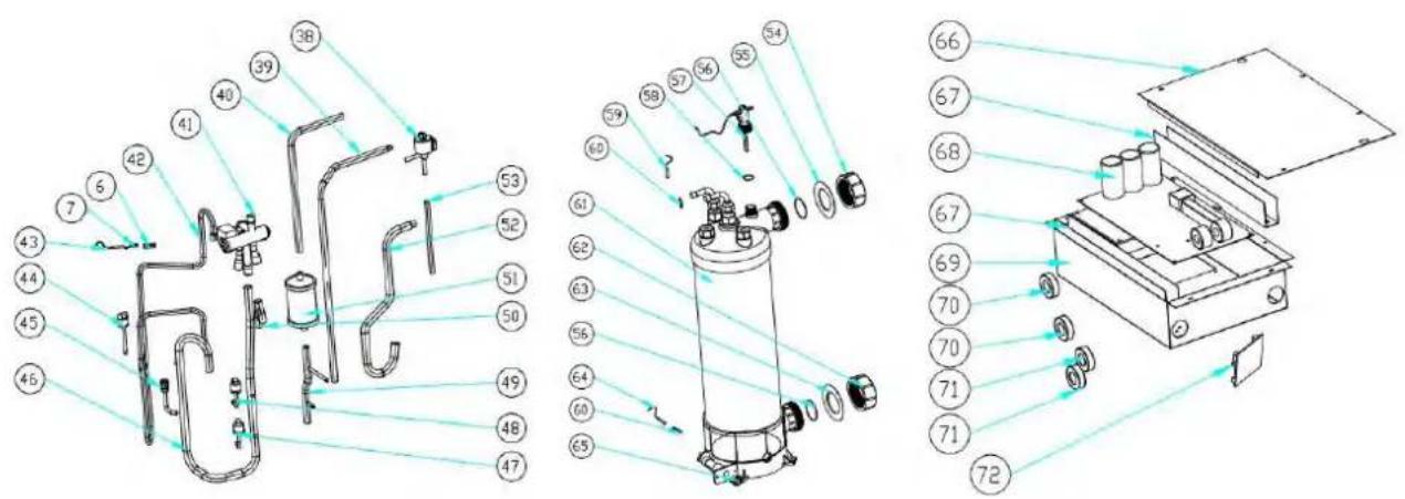
text_image
Technical diagram of a mechanical device with numbered components and exploded view, likely for assembly or manufacturing purposes.text_image
Exploded view diagram of an air conditioning unit with numbered components and lighting paths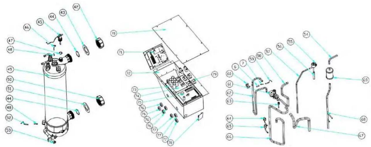
text_image
Exploded view diagram of a mechanical device with numbered parts and Chinese labelsnatural_image
Technical line drawing of a rectangular HVAC unit with internal fan and side panel, showing dimension annotations (716 and 19) — no readable text or symbols beyond measurement lines.
text_image
390 102.7
text_image
1075.7 127 450 405 417 469.5Modell : ELYO SMART NN 20
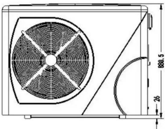
text_image
880.5 26
text_image
600 111.5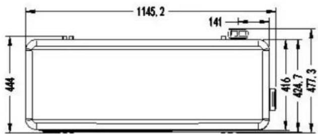
text_image
1145,2 141 444 416 424,7 477,31. Beschreibung
Modell :ELYO SMART NN 25/ 25T, ELYO SMART NN 30/ 30T

text_image
1291,5 25 1076 125,7 452 311 422,7 472,6
text_image
800 86.52. Transportinformationen
natural_image
Illustration of a brown cardboard box with a blue pallet jack beside it, next to a yellow pallet (no text or symbols)natural_image
Close-up of a black conical object with a metallic bolt and nut, resting on a wooden surface (no text or symbols visible)natural_image
Black plastic enclosure with a rectangular opening and mounting holes (no text or symbols visible)natural_image
Coiled white cable with a terminal connector (no text or symbols visible)10M Signaldraht, 1 Stk Modbus-Signaldraht, 1 Stk

natural_image
Two white plastic pipe fittings, one cylindrical and one threaded, shown against a dark background (no text or symbols visible)natural_image
White plastic bag wrapped in plastic wrap, no visible text or symbolsWinter-Abdeckung, 1 stk
4.2 Der Kit-Bypass
natural_image
3D rendering of a white and red pipe fitting with flanges (no text or symbols visible)text_image
2000mm Air out 800mm 1000mm Air inRef. ELYO SMART NN 06/09/12/16/20
text_image
Reactor Magnet ring (WHT) FAN RED 11 RED 12 Magnet ring (WHT) FAN2 OUT9 ON MOD 4-Way valve coil N6 N5 N4 OUT6 OUT5 OUT4 Base Electric heater Crankshaft electric heating N3 N2 N1 N9 OUT3 OUT2 OUT1 EEPROM Burning interface NO COM OUT10 NO 1/2 PE AC-N AC-L COM1 COM2 TH1 TH2 TH3 TH4 TH5 TH6 TH7 TH8 TH1 TH2 TH3 TH4 TH5 TH6 TH7 TH8 TS1 TS2 TS3 TS4 TS5 Electronic Expansion Valve Ambient temperature Coil Temperature Exhaust Temperature Water out temperature Water in temperature Wire controller A B GND Modbus Signal lines Defrosting switch High pressure switch Low pressure switch Magnet ring (BLK) BRN L N ⊕ 1 2 RED * The dotted line part are only used in some models I-3041 220V~50Hz Switchtext_image
Reactor Magnet ring (WHT) FAN RED 11 12 Magnet ring (WHT) FAN2 OUT9 ON MOD N6 N5 N4 OUT6 OUT5 OUT4 Crankshaft electric heating N3 N2 N1 OUT3 OUT2 OUT1 EEPROM Burning Interface COM NO OUT10 1 2 PE AC-N AC-L COM1 COM2 TH1 TH2 TH3 TH4 TH5 TH6 TH7 TH8 4/ TH1 TH2 TH3 TH4 TH5 TH6 TH7 TH8 Electronic Expansion Valve Ambient temperature Coil Temperature Exhaust Temperature Water out temperature Water in temperature CN21 LED1 LED2 LED3 LED4 LED5 CN22 CN23 RED CN24 YLV A3 BLK A2 CON10 Defrosting switch Water flow switch High pressure switch Low pressure switch BRN Magnet ring (BLK) BLU L N 1 2 Switch (PUMP) I-3041M * The dotted line part are only used in some modelsRef. ELYO SMART NN 25/30
text_image
Fan DC #1 Fan DC #2 5 line 5 line (WHT Magnet ring CN1) C14 CN1M FAN1 FAN2 CN51 CN607 C5 C58 T1 SW K21 SHQ050101 C46 C116 C120 C119 G L I1 N I2 DC-DC+ U V W P Magnet ring (BLK) RED RED REDA BLK Magnet ring (BLK) COMPRESSOR PE Switch RED RED PE BLU BLU C8 N- C39 C4 C38 TVS1 N- L-OUT R1 BRN L-OUT T2 C17 C14 R2 FU2 FU1 DC+ BLU DC+HMIFW-1 150V~100s I-5101 4 line Water flow switch Defrosting switch High pressure switches Low pressure switch FLS SYTOOLG GRESET Base Electric heater 4-Way valve coil Crankshaft electric heating RED BLU Electric heating of water tank NC NO COM RED RED PE Magnet ring (WHT) BRN Magnet ring (BLK) BRN BLU PE 220V ~ 50Hz Water in temperature Water out temperature Exhaust Temperature Coil Temperature Ambient temperature 4 line Wire controller Electronic expansion valve CN2text_image
Fan DC #1 Fan DC #2 WHT Magnet ring CN14 CN14 CN14 CN14 CN14 CN14 CN14 CN14 CN14 CN14 CN14 CN14 CN14 CN14 CN14 CN14 CN14 CN14 CN14 CN14 CN14 CN14 CN14 CN14 CN14 CN14 CN14 CN14 CN14 CN14 CN14 CN14 CN14 CN14 SNV C12 T1 K21 SW C5 CS8 S7 P SHQ050101 C46 C116 C120 C119 G L I1 N I2 Magnet ring (BLK) RED RED RBC DC DC U V W P Magnet ring (BLK) COMPRESSOR PE BLU BLU BRN BRN T2 C17 C14 R2 FLU2 FU1 L DC HMF1W-1 150/305 I-5101M * The dotted line part are only used in some models 4 line Water flow switch Defraining switch High pressure switch Low pressure switch FLS 3) TOOL0 GRESET Base Electric heater 4-Way valve coil Crankshaft electric heating RED BLU Electric heating of water tank RED RED PE Switch Magnet ring (WHT) BRN SHZKA0101 Water in temperature Water out temperature Exhaust Temperature Coil Temperature Ambient temperature COOL/VFI CAN3 DN4 CONJ COMI CONI COMD Wire controller Electronic expansion valve COM L L N L N 220V~50Hz LED1 LED2 LED3 LED4 LED5 LED6 LED7 LED8 LED9 3 Modbus Wire controllertext_image
SHQ05T0101 R S T I1 DC- I2 DC+ U V W Magnet ring (BLK) Reactor COMPRESSOR PE T' T1' S' S1' R' N' N1' BLU DC- RED DC+ GND PE T1" S1" R1" N1" BLK Magnet ring (BLK) Base Electric heater 4-Way valve coil Crankshaft electric heating Electric heating of water tank PUMP SWITCH RED PE RED BLU BLU BLU 380-415V 3N~50Hz FAN 1 DC FAN 2 DC Magnet ring (WHT) N BLU OUT1' OUT2' OUT3' OUT4' OUT5' OUT6' OUT7' OUT8' OUT9' OUT10 Magnet ring (WHT) 4 line Water flow switch Defrosting switch High pressure switch Low pressure switch SHZKA0101 W/LOU/GRESI FLS W/LOU/GRESI SHQ05T0101 Water in temperature Water out temperature Exhaust Temperature Coil Temperature Ambient temperature COM1.WIFI CN3 CN4 COM1.L.COM.L.COM.L.D. CN2 CN26 Wire controller 5 line Electronic expansion valve * The dotted line part are only used in some models I-531text_image
I-531M * The dotted line part are only used in some models SHQ05T0101 R S T I1 DC-I2 DC+ U V W Magnet ring (BLK) REDA BLK Magnet ring (BLK) COMPRESSOR PE RED T' T1' S' S1' R' N' N1' BLU DC- RED DC+ GND PE T1" S1" R1" N1" BLK R N BLU DC+ 4 line FAN 1 DC 5 FAN 2 DC 5 Magnet ring (WHT) BLU OUT1 OUT2 OUT3 OUT4 N4 N5 N6 N7 N8 N9 N10 PUMP SWITCH RED PE A B C N 380-415V 3N-50Hz Magnet ring BLU Electric heating of water tank RED BLU LED BLU Magnet ring (WHT) SHZKA0101 Water flow switch Defrosting switch High pressure switch Low pressure switch Water in temperature Water out temperature Exhaust Temperature Coil Temperature Ambient temperature COM WIFI CN3 CN4 CN2 CN5 COM_LOCM_COM_D Wire controller 5 line Electronic expansion valvenatural_image
Front view of a medical device with blue screen and control buttons (no visible text or symbols)
natural_image
Close-up of a black cable with green wires against a wooden background (no text or symbols visible)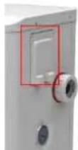
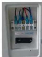
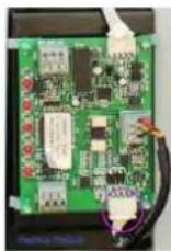

natural_image
Close-up of a green printed circuit board with visible traces and components (no readable text or symbols)6.7 Installation of the Modbus/Fluidra Connect Signal Wire
(6) (7) (8) (9)
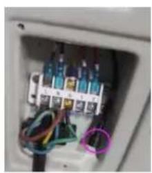
natural_image
Interior view of an electrical enclosure showing wiring and components (no visible text or symbols)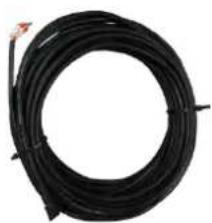
natural_image
Coiled black cable with a red connector at the top (no text or symbols visible)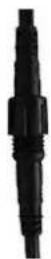
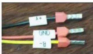
text_image
A+ (5NL) -8text_image
Heat Licht antext_image
Technical diagram of an industrial machine with numbered components for identification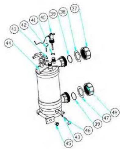
text_image
Technical diagram of a mechanical device with numbered components and light rays indicating assembly or inspection.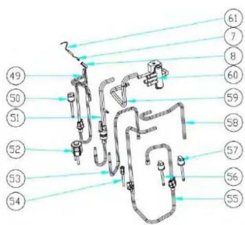
text_image
49 50 51 52 53 54 61 7 8 60 59 58 57 56 55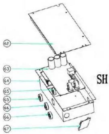
text_image
62 63 64 65 65 66 66 67 SHtext_image
Technical diagram of an air conditioning unit with numbered components and exploded viewstext_image
Exploded view diagram of an air conditioning unit with numbered components for identification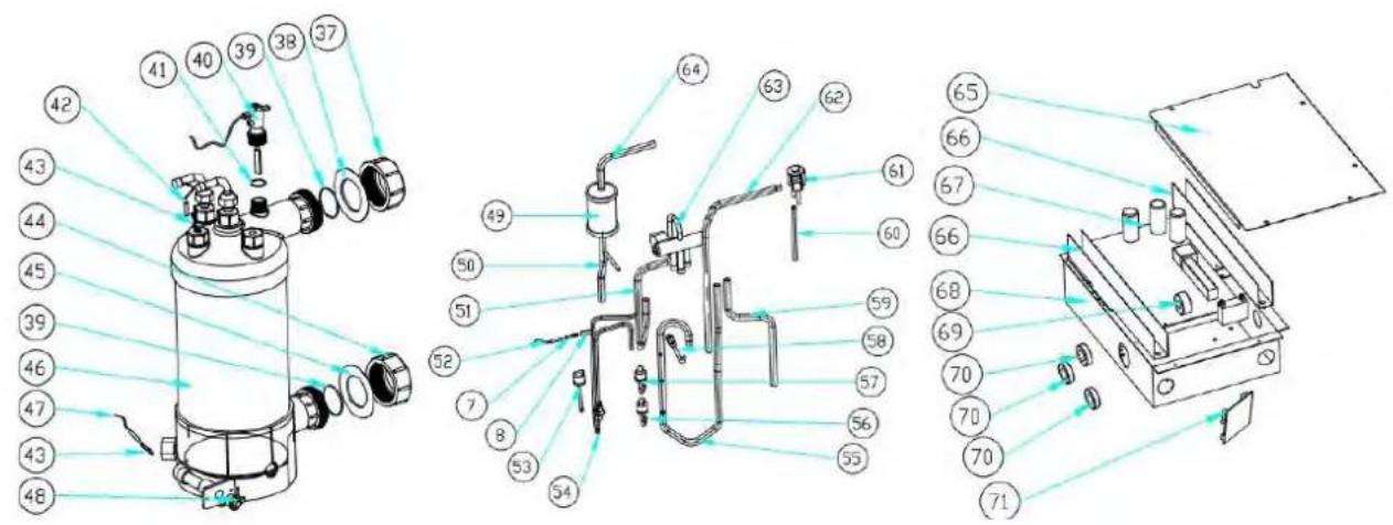
text_image
Technical diagram of a mechanical device with numbered components and exploded view, likely for assembly or manufacturing purposes.text_image
Exploded view diagram of a refrigerator internal components with numbered labels for identification.natural_image
Technical line drawing of a mechanical fan or air conditioning unit with dimension annotations (716 and 19) — no readable text or symbols beyond measurement lines.
text_image
390 102.7
text_image
1075.7 127 450 406 417 469.5Modello: ELYO SMART NN 20

natural_image
Technical line drawing of a fan or vent system with dimension annotations (no text labels or symbols)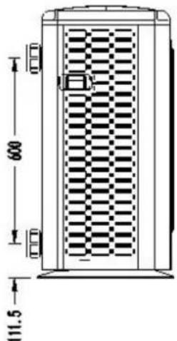
text_image
600 111.5
text_image
1145.2 141 444 416 424.7 477.31. Descrizione
Modello: ELYO SMART NN 25/ 25T, ELYO SMART NN 30/ 30T

text_image
129.5 25 1076 125.7 452 311 422.7 472.6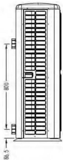
text_image
800 86.5natural_image
Illustration of a brown cardboard box with a blue pallet jack beside it, no text or symbols present.natural_image
3D rendering of a white and red pipe fitting with flanges (no text or symbols visible)text_image
2000mm Air out 800mm 1000mm Air intext_image
Check-valve Filter P-trap Check-valve In-line Chlorinator or Brominator Chlorinator Water Pumptext_image
Heat pump Power cable inlet Outlet Inlet Condensed water draining pipe Draining nozzle Water processor Side connection valve Discharge water pool Pool water inlet Water pump FilterRef. ELYO SMART NN 06/09/12/16/20
text_image
Reactor Magnet ring (WHT) FAN RED I1 12 Magnet ring (WHT) FAN2 OUT9 N0 MOD 4-Way valve coil N6 N5 N4 OUT5 OUT4 Base Electric heater Crankshaft electric heating N3 N2 N1 N9 OUT6 OUT5 OUT4 OUT3 OUT2 OUT1 EEPROM Burning interface N0 COM OUT10 1 2 PE AC-N AC-L COM1 COM2 TIH1 TIH2 TIH3 TIH4 TIH5 TIH6 TIH7 TIH8 TIH1 TIH2 TIH3 TIH4 TIH5 TIH6 TIH7 TIH8 Ambient temperature Coil Temperature Exhaust Temperature Water out temperature Water in temperature Wire controller A+B-GND' Modbus Signal lines Defrosting switch High pressure switch Low pressure switch Magnet ring (BLK) BRN L N ⊕ 1 2 RED 220V~50Hz Switch Magnet ring (BLK) COMPRESSOR Electronic Expansion Valve W V U RED BLK WHT * The dotted line part are only used in some models I-3041Ref. ELYO SMART NN 25/30
text_image
Fan DC #1 Fan DC #2 5 line 5 line (WHT Magnet ring CN17) C14 CN14 FAN FAN3 CN51 CN809 C5 L58 T1 SW K21 SHQ050101 C46 C116 C120 C119 G L I1 N I2 DC-DC+ U V W P Magnet ring (BLK) RED RED RED BLK Magnet ring (BLK) COMPRESSOR PE BLU N-OUT R1 BRN L-OUT T2 C17 C14 DC1 R2 FU2 FU1 BLU DC HMF1W-1 15091005 I - 5101 4 line Water flow switch De-croting switch High pressure switch Low pressure switch FLS 5/TOOLO GRESET Base Electric heater 4-Way valve coil Crankshaft electric heating RED BLU Electric heating of water tank RED RED PE Switch Magnet ring (WHT) BRN A052 VS 9L104 SHZKA0101 Water in temperature Water out temperature Exhaust Temperature Coil Temperature Ambient temperature 4 line 5 line Wire controller Electronic expansion valve BRN BLU PE 220V ~ 50Hz * The dotted line part are only used in some modelstext_image
Fan DC #1 Fan DC 5 line 5 line (WHT Magnet ring CN14 CN13 CN12 CN9 CN8 CN7 CN6 CN5 CN4 CN3 CN2 CN1 C14 CN14 C12 FAM1 FAM2 T1 SW K21 SHQ050101 C46 C116 C120 C119 G L I1 N I2 DC DC U V W P Magnet ring RED RED BLK WHT COMPRESSOR PE Switch BLU BLU BRN Magnet ring (BLK) BLU N-OUT R1 C39 C4 C38 TVS1 N L-OUT L1 DC+ R2 FU2 FU1 L DC HMF1W-1 150V/105 0 1 2 3 4 5 6 7 8 9 I-5101M 4 line Water flow switch Defrosting switch Low pressure switch Base Electric heater 4-Way valve coil Crankshaft electric heating RED BLU Electric heating of water lank Magnet ring (WHT) BRN Magnet ring (BLK) BRN 220V ~ 50Hz Water in temperature Water out temperature Exhaust Temperature Coil Temperature Ambienttemperature SHZKA0101 4 line Wire controller CN2 COM LOON COM D CN4 CONJEL CH3 CN4 SHZKA0101 4 line Electronic expansion valve Wire controller * The dotted line part are only used in some modelsnatural_image
Close-up of a medical device with blue panel and control buttons (no visible text or symbols)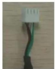
natural_image
Close-up of a white and green electrical connector with black wires, against a wooden background (no text or symbols visible)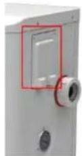
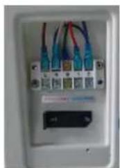
natural_image
Close-up of a white electrical outlet with multiple connected cables and a small black indicator block (no visible text or symbols)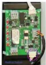
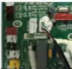
natural_image
Close-up of a person working on a circuit board with electronic components (no visible text or symbols)natural_image
Interior view of an electrical enclosure showing wiring and components (no visible text or symbols)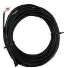
natural_image
Coiled black cable or wire with a small red mark at the top (no text or symbols visible)
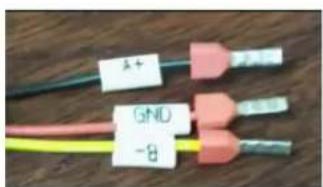
text_image
1+ GND -8text_image
Technical diagram of an industrial machine with numbered components for identification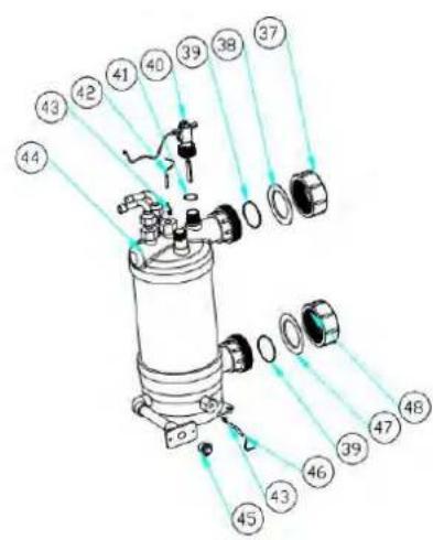
text_image
Exploded view diagram of a mechanical assembly with numbered parts for identification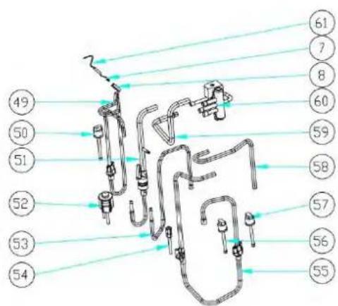
text_image
Technical diagram of a mechanical assembly with numbered components and connecting lines indicating connections or parts.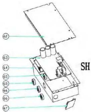
text_image
62 63 64 65 65 66 66 67 SHtext_image
Exploded view diagram of an air conditioning unit with numbered components for identification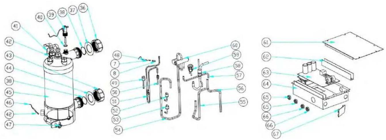
text_image
Technical diagram of a mechanical device with numbered components and exploded view, likely for assembly or manufacturing purposes.text_image
Exploded view diagram of an air conditioning unit with numbered components for identification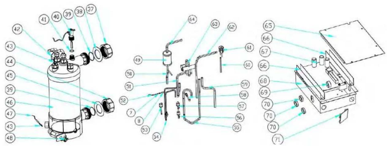
text_image
Technical diagram of a mechanical device with numbered components and exploded view, likely for assembly or manufacturing purposes.text_image
Exploded view diagram of an air conditioning unit with numbered components for identification