
Viron Connect 10 - Swimming Pool ASTRALPOOL - Free user manual and instructions
Find the device manual for free Viron Connect 10 ASTRALPOOL in PDF.


| Product Type | Pool Pump with Integrated Control |
| Model | Viron Connect 10 |
| Brand | AstralPool |
| Power Supply | 230 V / 50 Hz |
| Power Consumption | 0.75 kW |
| Max Flow Rate | 10 m³/h |
| Max Head | 8 m |
| Dimensions (L x W x H) | 400 x 250 x 300 mm |
| Weight | 12 kg |
| Connection Size | 50 mm (2") |
| Noise Level | < 70 dB(A) |
| Protection Rating | IPX5 |
| Functions | Filtration, Circulation, Built-in Timer |
| Control Type | Digital Display with Remote Control |
| Filtration System | Cartridge or Sand Filter Compatible |
| Maintenance | Clean pump strainer basket regularly; backwash filter as needed |
| Safety Features | Overload protection, Thermal cut-off, GFCI compatible |
| Spare Parts Availability | Seal kit, impeller, control board available |
| Warranty | 2 years |
Frequently Asked Questions - Viron Connect 10 ASTRALPOOL
User questions about Viron Connect 10 ASTRALPOOL
0 question about this device. Answer the ones you know or ask your own.
Ask a new question about this device
Download the instructions for your Swimming Pool in PDF format for free! Find your manual Viron Connect 10 - ASTRALPOOL and take your electronic device back in hand. On this page are published all the documents necessary for the use of your device. Viron Connect 10 by ASTRALPOOL.
USER MANUAL Viron Connect 10 ASTRALPOOL
Pool and Spa Controller
ASTRALPOOL

INSTALLATION AND
OPERATING INSTRUCTIONS

CONNECT 10 IOM INST 314
Congratulations on the purchase of your AstralPool Viron Connect 10 controller. Correct installaon and set up by a qualified and/or licensed technician will ensure you have many years of trouble free enjoyment from your swimming pool.
- The Power Supply Module must be hard wired by a licensed electrician. To avoid a safety hazard, the supply cord if damaged, must only be replaced by AstralPool, its service agent or a suitably qualified person.
• This controller is not intended for use by young children or inrm persons without supervision.
Please ensure that young children are supervised to ensure that they do not interfere with the Pool and Spa Equipment Centre.

WARNING
FOR YOUR SAFETY – This product must only be installed and serviced by an electrician or professional pool technician. The informaon and processes in this manual must be followed exactly. Failure to follow warning noces and instrucons may result in property damage, serious injury or death. Improper installaon and/or operaon may void your warranty.

For full warranty terms and conditions and to register your warranty, simply visit www.astralpool.com.au/warranty and complete your details. Or scan the QR code and be taken directly to the registration page.
Record your equipment details here for quick reference:
Model No.:
Serial No.:
Record your Equipment details here for quick reference:
Model No.: ____
Serial No.: ____
Table of Contents
Secon 1 Overview....5
Components .... 5
Basic Operaon ....5
Secon 2 Equipment Operaon....6
Pool & Spa 6
Lighng 6
Heang 7
Solar 7
Favourites 8
Secon 3 Seng the Clock 9
Clock seng 9
Secon 4 Timer Programming ....10
Seng mers 10
Secon 5 Favourite Programming....16
Seng favourites....17
Secon 6 Equipment Installaon....18
Control box installaon 19
Touchscreen installaon....19
Equipment conncon - electrical....20
Equipment conncon – data/communicaons 21
Secon 7 Installaon Setup....22
Touchscreen Setup 22
Secon 8 Wireless Conguraon....33
Wireless Transceiver installaon....35
RF Remote installaon....36
Secon 9 External Heater
Control....37
Secon 10 Solar Control via motorised valve....37
Secon 11 Touch Screen Installaon....38
Secon 12 Customisable Switching from an external Source....47
Secon 13 Service Mode Operaon ....48
Secon 14 Funconality Tips....49
Secon 15 Troubleshoong....50
Secon 16 Assigning outlets/channels ....51
Warranty - Terms and Condions ....52
Warranty - Exclusions ....53
Table of Contents Part Two: Internet Gateway and Smart Phone App Installaon
Installing the Internet Gateway and Smart Phone/Tablet App....54
Installing Internet Gateway hardware to the Connect 10....55
Conguring home Wi-Fi....58
Registering 'Pool Owner' and authorized 'Users'....59
Internet Serial Number and Password....61
Download connectmypool app to your SmartPhone or Tablet....62
Internet Gateway and App trouble shoong....69
Secon 1. Overview
The informaon contained within this manual will provide instrucons on the operaon and installaon of your Viron Connect 10 Pool and Spa control system. These instrucons should be followed exactly to ensure correct and safe operaon of the controller. It is important that these instrucons be read completely prior to installaon or operaon of the controller. These instrucons are current for touchscreen version 1.7 onwards.
1.1 Components
a. Viron Connect 10 Pool and Spa Controller equipment center (supplied)
b. Touchscreen Controller (supplied)
c. RF handheld remote (oponal)
d. Wireless Transceiver module (oponal)
e. Temperature sensors for gas, electric and solar heang systems (oponal)
f. RJ12 data cables for auxiliary equipment conncon (oponal)
g. Internet Gateway (oponal)
1.2 Basic Operaon
a. Ability to control 8 appliances through ON/OFF/AUTO selecon
b. Service mode operaon available from equipment center control panel for manual override
c. Customizable 'Favorites' programs to allow for single touch operaon of mulple appliances
d. Use of up to 8 mer periods each day to automacally turn on equipment
e. Fully automate enre pool system through product integraon and programming
Secon 2. Equipment Operaon
All appliances on your Viron Connect controller can be easily operated through the specic product screens.
2.1 Pool & Spa Opon
a. Select Pool & Spa Icon from the menu screen
b. All equipment not allocated to a specific category (ie Lighng, Heang, etc) will be located in the Pool & Spa menu.
c. Select the piece of equipment you want to turn on or o. Depending on conguraon of mers you will be able to toggle between ON / OFF / AUTO
d. If installed and congured, your heater (gas or electric) can also be turned on and o from this menu opon. For temperature adjustment, please see Heang opon (2.3)
e. Operaon of motorized valves for pool / spa combinaons can be selected by choosing either the POOL or SPA icon.
f. Separately allocated and named valves (valve 1 & valve 2) can be operated from this Icon also

2.2 Lighng
a. Select Lighng Icon from the menu screen
b. All lighng channels which have been allocated to a zone will be displayed in the lighng secon
c. Select between ON/OFF or AUTO (auto will also be shown if another product has a mer allocated to it)
d. For AstralPool Delta mul-colour lighng systems, you can also change the colour seng of your light by tapping on the colour chip at right of screen to expose the full color palee

2.3 Heang (if applicable)
a. Select Heang from the menu screen
b. The current water temperature and the set temperature will be shown on the screen. If using pool and spa mode, dierent water temperature set points can be chosen for both.
c. To adjust the set temperature, rst select either pool or spa. Then using the up and down arrows to the right of the set temperature adjust to desired seng.
d. Use the Heater ON / OFF buon to operate your heater (water ow must be present before heater will funcon). Configure heating Tue 12:50

2.4 Solar (if applicable)
a. Select Solar from the menu screen
b. Adjust set temperature to desired seng.
c. Select Solar On / O / Auto
i. O - turns solar manually o
ii. On – turns solar manually on
iii. Auto - turns solar to automac operaon. If sucient heat dience between pool water and collector temperature solar will operate. Dierenal is set at initial installaon set-up stage.
d. Select Summer / Winter
i. Summer – normal operaon of solar
ii. Winter – solar pump will operate for 5 minutes per day to ush collector (only if AUTO is selected)

2.5 Favorites
a. Select Favorite opon from the menu screen
b. Acvate one of the preset favorites by selecng from the list (to program favorites see Secon 5)
c. Once nished with a Favorite seng, you can return system to programmed sengs by selecng "All Auto" from the home screen. A favourite opon initiated will override all other mers

Note: It is recommended that the system always be set to the 'AUTOMATIC RETURN TO POOL MODE', which can be found in the initial set up and installaon menu
Secon 3. Seng the Time
3.1 To set the current me on the Viron Connect touchscreen, select the Setup Icon from the main menu then select Set Time.
3.2 Using the up and down arrows, set the current hour, minutes and day (the clock default seng is using the 24 hour clock format, but 12 hour can be selected is desired)

3.3 Select done when completed.
Secon 4. Timer Programming
4.1 Your Viron Connect controller has 8 programmable mers that can be set to operate at any me during the day. You can choose to run your mers on an 'Everyday', 'Weekend', or 'Other' seng. On selecon of your chosen daily mers, the corresponding starng leer of that selecon will appear next to the mer (i.e 'E', 'W', or 'O'). When seng your mers, it is essenal that you do not allow any mer period, or day selecon, to cross over into another. Crossing over mers, or days, can cause conict within the soware of the controller and result in errac operaon of equipment.
a. Select Timers from the menu screen
b. Starting with Timer 1, select 'Setup'
c. If congured, select if mer is to operate in Pool or Spa mode, then select Next
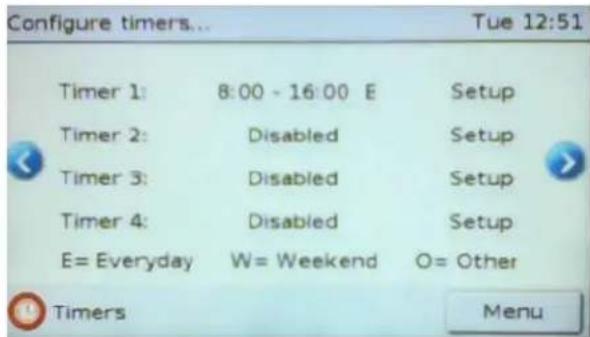
d. Select the check box next to each appliance you require to operate during the mer period then select Next.

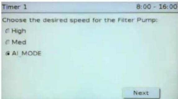
e. If system is congured with a variable (mul) speed AstralPool pump, you will be prompted to select the desired speed for the Filter Pump from Low, Med or High (funcon only accessible with use of RJ12 Data cable). If you are also using an Astralpool chlorinator with ORP and PH control and have enabled AI mode, this will then be a selectable speed opon, (AI mode would have been previously selected in initial set-up mode). If AI mode has been programmed you will not have the opon to select low speed. Select next.
f. Any auxiliary valves which have been installed can be set to on or o. If valve is to be operang, select check box. Select next. Timer 1 8:00 - 16:00

g. Choose heater status (if installed). Select next.

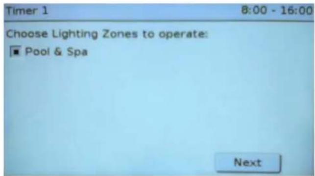
h. Choose to acvate lightng zones (if installed). Select next.
i. Select the 'Disabled' opon next to the mer you wish to set- This will then allow you to add a mer for this period.

j. Using the arrows adjust the starng and nishing me for the mer period. Once seng the mer has begun, the 'enabled' square automacally becomes acvated as a default. To deacvate this mer, simply press the enabled square so that it no longer has a black center. Press done buon when nished.

k. Repeat above process for each additional mer period required.
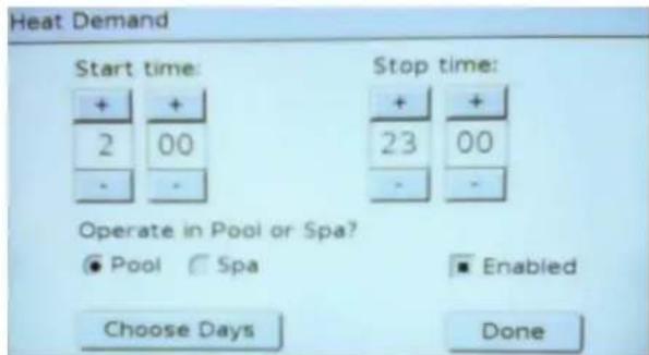
- The nal mer period (if congured in your setup) is for 'Heat Demand'. This feature allows you to bring your Itraon or heang pump on at the top of each hour to sample the water temperature of your pool or spa. If the temperature is below the set point, the pump will connue to operate until the desired temperature is achieved then it will switch o. To program heat demand;
i. Go to the boom of the mer list and nd Heat Demand, (note this mer will not appear unless previously congured), touch on the word 'Disabled'.

ii. Program start and stop period using the arrows beside the mes. Select if system should be operating in the pool or the spa mode.
NOTE : ONCE ALL TIMERS HAVE BEEN PROGRAMMED, ENSURE NO TIMER PERIODS OR DAYS ARE OVERLAPPING BEFORE CONTINUING.
m. When nished with seng mers, select the 'Menu' buon to return to the main screen. Next, select the 'Home' opon which will display a screen giving you 3 opons.
i. All O
ii. All Auto
iii. Menu
n. Select the 'All Auto' opon. Your Viron Connect controller will now operate as per the automac programming you have just entered.
o. In your 'Home' Icon you will now see a rolling display, in a number of dierent windows, of what products you have congured and the current state in which they are in.

Secon 5. Favorite Programming
5.1 The AstralPool Viron Connect 10 control system allows you to program 'One Touch' Favorite sengs so you can operate numerous products at the same me for specie purposes. A total of 8 favorite sengs can be programmed, allowing you to have things such as 'Night Swim', 'Spa party', 'waterfall feature' etc.
5.2 To program a new favorite seng (or to modify an exisng one),
a. Select the 'Setup' opon from the main menu screen. If it does not appear in this rst window, scroll right with the 'more' buon.

b. From the Setup menu, select 'Congure Favorites'.

c. The Viron Connect 10 controller comes with 8 programmable favorites. 2 pre-congured for your convenience 'Pool' & 'Spa', which can also be modified, and 6 additional favorite allocaons that can be programmed to your specific requirements.

d. Select 'Favorite 1' from the list. You will then be given 3 opons on the next page.
e. Select edit name. This is where you will be able to re-name the favorite, (rst delete the name 'Favorite'), then add your customized name,
f. Next select 'Edit Conguraon', this is where you choose what products you want to come on in that favorite. Aer selecng all of the products that you want, you will then be taken back to the 'Edit' window.

g. At this stage, select the 'Back' buon. This will take you back to the newly named favorite, where you will see the word 'Disable' sll appear next to the newly named favorite. Press this so that the name changes to 'Enable'. Selecng this will then allow the newly congured favorite to be accessible from the 'Favorites' Icon.
Secon 6. Equipment Installaon

WARNING
FOR YOUR SAFETY – This product must only be installed and serviced by an electrician or professional pool technician. The informaon and processes in this manual must be followed exactly. Failure to follow warning noces and instrucons may result in property damage, serious injury or death. Improper installaon and/or operaon may void your warranty.
This appliance must be installed in accordance with AS/NZS 3000:2007 and any other local regulaons.
All equipment to be operated from the Viron controller should be connected prior to establishing power to the control box. This includes both power cables and RJ12 data cables. All RJ12 data cables used in AstralPool communicaon systems are a straight through conguraon. The use of cross over cables may cause damage to your system and void warranty.
The combined total load all equipment connected to the Viron controller must not exceed 40 amps.
An approved isolaon switch must be installed in the electrical line to the Viron Connect controller. This switch must be posioned in close proximity to the control box.
The Viron Connect control system is not intended for use by young children or inrm persons without supervision. Please ensure that young children are supervised to ensure they do not play with the controller.
The control box must be hard wired by a licensed electrician to a minimum 32amp circuit – 40 amp circuit is recommended. To avoid a safety hazard, the supply cord if damaged must only be replaced by AstralPool, its service agent or a suitably qualified person.
Power to the control box should be supplied by an isolang transformer or through a residual current device (RCD) with a rated residual operang current not exceeding 30mA.
The Touchscreen control may be removed on its extendable lead for programming purposes and refitted inside the Relay box. Alternatively, with the purchase of a longer RJ 12 six wire flat cable the touch screen may be moved inside the house or under a balcony and mounted for regular use. Warning: Do not mount touch screen in direct sunlight or with direct exposure to the elements.will void warranty.
6.1 Control Box Installaon
a. The Viron Connect 10 electrical box has an IPX3 rang enabling it to be installed outside. Regulaons within AS/NZS 3000:2007 require that the electrical box be installed outside of the pool zone. This pool zone extends 3.5m from the edge of the swimming pool.
b. The electrical box should be installed in a well venlated posion, away from direct sunlight and out of the direct weather where possible. Ensure the unit is not located near pool chemicals as fumes may damage the sensitive electrical components.
c. The electrical box is supplied with masonry plugs and screws. When moung onto a solid wall, ensure the lowest part of the controller is a minimum of 1600mm above ground level. If being mounted onto a post, a weatherproof panel must be used behind the equipment box. This panel must extend 150mm past each side and top/boom of the controller.
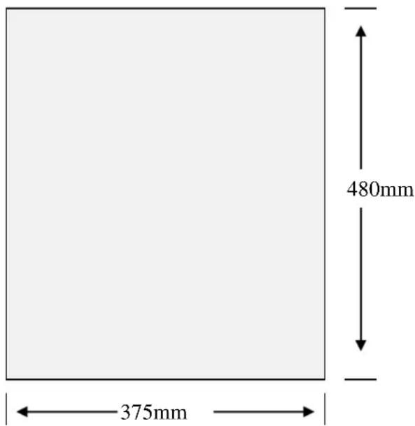
Electrical box dimensions :
6.2 Touchscreen Installaon
*NOTE- FOR FULL AND DETAILED TOUCHSCREEN INSTALLATION DETAILS REFER TO SECTION 11.
THE TOUCHSCREEN SUPPLIED WITH THE VIRON CONNECT CONTROLLER SYSTEM IS DESIGNED FOR INDOOR INSTALLATION ONLY.
a. Connecon of the touchscreen to the electrical control box is made by a 6 wire RJ12 straight through cable. If cable conncon back to the electrical box is not possible, wireless Transceiver modules can be purchased from AstralPool.

Appliance Installaon / Connecon - Power
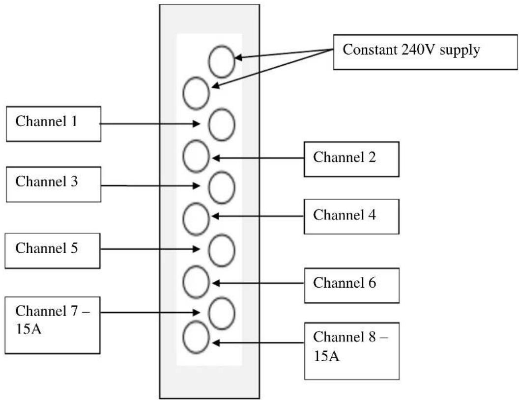
b. The Viron Connect controller comes with 8 x 10A GPOs and 2 x 15A GPOs. Two of the 10A outlets supply a constant 240V output for conneccon of appliances which require acve power such as gas pool heaters. The other eight outlets are all switchable from the controller.
c. When connecng appliances to the outlets of the controller, aempt where possible to start at channel 1 and use sequential channels from there. This will ensure the easiest operaon of the controller.
flowchart
graph TD
    A["Channel 1"] --> B["○"]
    C["Channel 3"] --> D["○"]
    E["Channel 5"] --> F["○"]
    G["Channel 7 - 15A"] --> H["○"]
    B --> I["Constant 240V supply"]
    D --> I
    F --> J["Channel 2"]
    F --> K["Channel 4"]
    F --> L["Channel 6"]
    H --> M["Channel 8 - 15A"]
6.3 Appliance Installaon / Connecon – Communicaons
a. The Viron Connect controller communicates with other compatible AstralPool equipment through the use of sophisticated soware and RJ12 data cables. All appliances with communicaon ability should be linked back to the controller via data cable. AstralPool products capable of this conneccon include;
i. Viron eVo series pool and spa heaters
ii. Viron eVo series variable speed pumps
iii. Viron series salt chlorinators
iv. Delta lighng systems
v. RolaChem dosing systems
vi. VX series salt chlorinators
vii. HX and JX series pool heaters
viii. HiNRG pool heaters
b. When connecng any appliance via data cable to the electrical box, it is important to only use straight through cable. Many o the shelf data/phone cables are cross over conguraon and cannot be used with the Viron control system. RJ12 cables of varying lengths are available from your local AstralPool Australia distributor.
c. There are 6 x RJ12 sockets located inside the Viron controller. Any appliance can connect to any socket.
d. There are 4 x valve actuator sockets located inside the Viron controller. Actuators must be 24VAC and have a maximum current draw of 0.75A. For pool/spa operaon, use actuator ports labeled inlet and outlet. For the 2 auxiliary valves (which can be used for water features, solar, etc) use ports labeled Valve 1 or Valve 2.

Secon 7. Installaon Setup
7.1 Touchscreen Controller Setup
1) From the main screen, select the 'Setup' Icon. Scroll to next page if not displayed on main page.

2) Scroll down through the screen to select the 'Installaon Setup' icon.

3) Enter in the password of 1 2 3 4
4) A summary of the current equipment conguration will be shown on the screen - it will be a generic default factory seng. Select the 'Change' Icon to connue with the setup.
5) The next screen will then prompt you to use either the 'SET UP WIZARD' or the 'JUMP TO 'secon. For the initial set-up, the 'SET UP WIZARD' will need to be used to enable full and complete programming of the connect 10. If at any other stage aer the initial set-up other programming has to changed, then the use of the 'JUMP TO' secon could be used.
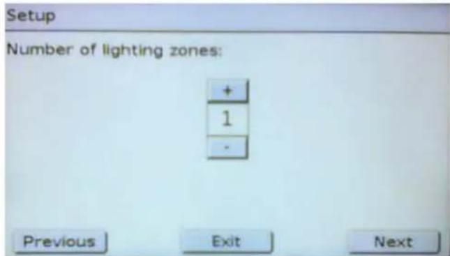
6) The next screen is the number of lightng zones that you want to select, or allocate, to the 'Lighng' Icon. A zone is any area of the pool and surrounds with lightng that you want to turn on separately. Aer selecon press next.
| Use SETUP WIZARD | |
| Or jump to a section: | |
| Heating | Chemistry |
| Channel | Solar |
| AUX Valve | Lighting |
| Exit |
7) You will need to nominate the name of each lighng zone from the provided list and select if the zone supports mul-colour lighng. Only select the mul-colour check box if you are using an AstralPool Delta lighng controller.

8) Select the number of channels being used in the system. For Connect 10 controllers, select 8 channels.

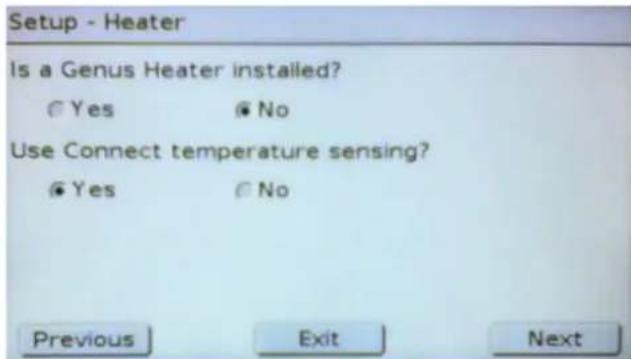
9) Select if a Genus heater is installed. 'Genus' heaters include all gas heaters manufactured by AstralPool Australia including the Viron eVo range, HiNRG range, HX range and JX range.

i. If YES go forward to step 10;
ii. If NO, you will be given the opon of using the relay board within the controller to monitor the water temperature. If you have a non AstralPool heater aached, select YES to relay board temperature sensing;
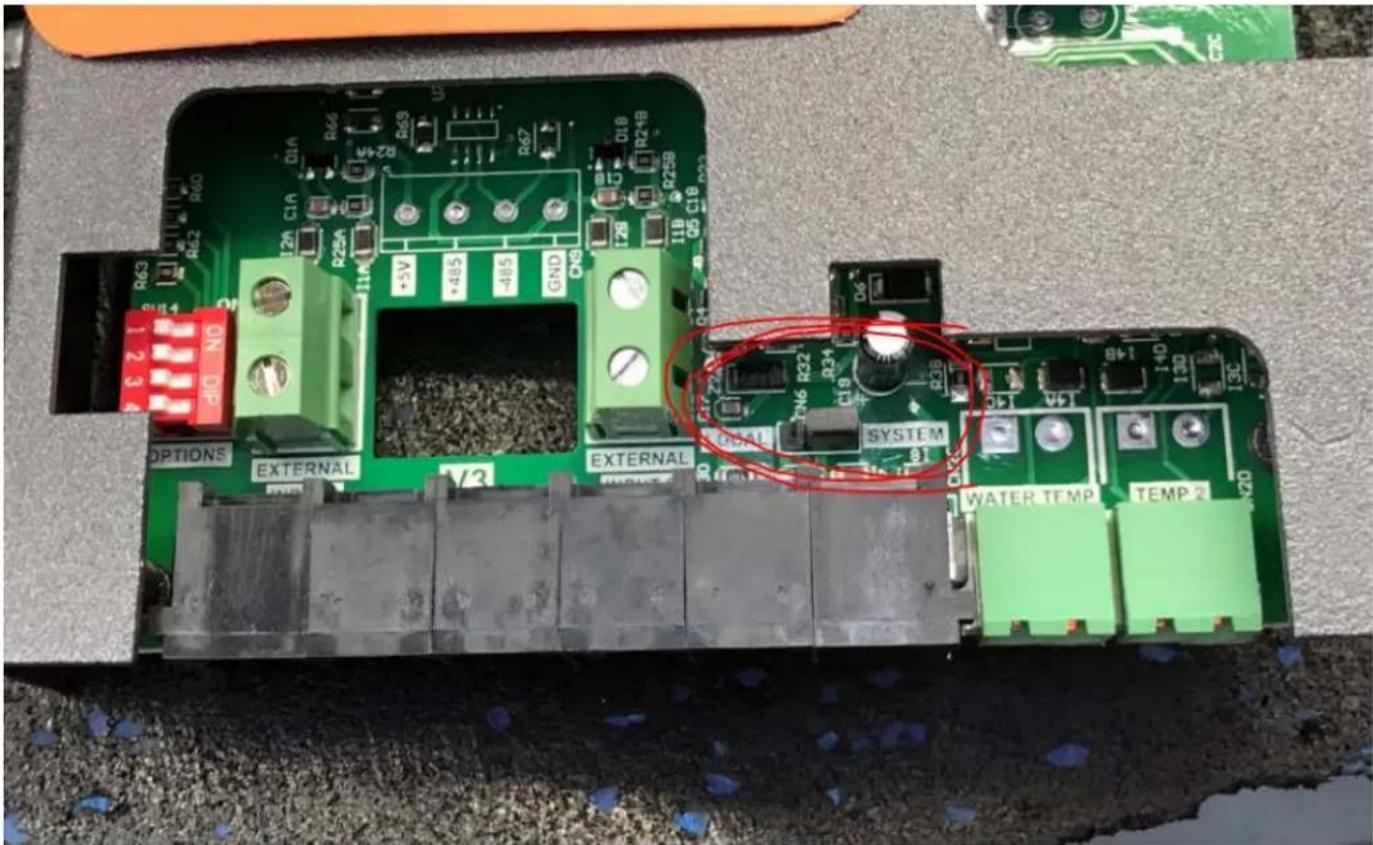
iii. NOTE- THE CONNECT 10 COMES CONFIGURED TO COMMUNICATE WITH A GENUS HEATER, THE UNIT MUST BE MANUALLY RE-CONFIGURED IF NO IS SELECTED. THIS PROCEDURE IS DONE BY FIRST TURNING POWER OFF TO UNIT, THEN TAKE OFF THE ELECTRICAL COVER PANEL TO EXPOSE ALL WIRING.
iv. AT THIS STAGE LOCATE SYSTEM/LOCAL PIN CONFIGURATION AS SHOWN BELOW, SLIDE PLASTIC BRIDGING PIN FROM MIDDLE/RIGHT POSITION, TO MIDDLE/LEFT POSITION SO THIS INDICATES LOCAL MODE.
v. Picture of SYSTEM conguraon

Picture of Local Configuration

SHOWING LOCATION OF LOCAL/SYSTEM PLUG
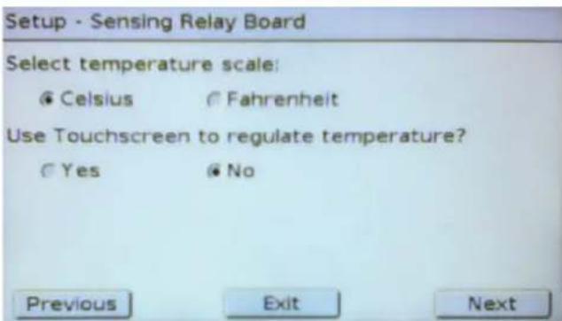
vi. If you select to use the relay board for temperature sensing, you can then choose if the display is in Celsius or Fahrenheit and if you want to use the touchscreen to regulate temperature. If you have an external heater (not manufactured by AstralPool) and you want to control your pool temperature from the Connect controller, select YES. To operate temperature control from the touchscreen you will need to install a temperature sensor kit available from AstralPool.
10) Select if Solar Control feature is being used from the Viron Connect.
i. If NONE go forward to step 11

ii. Select 'Connect Inbuilt' if using connect 10 solar control, then press next
iii. If NONE go forward to step 11
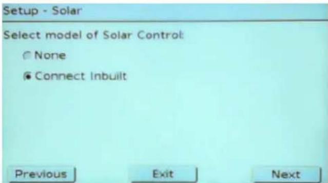
iv. Select if you require the collector to ush daily. AstralPool recommend acvang this feature to ensure water does not stagnate within the collector. Also select if you are operang the solar from the Itraon pump. If a separate pump has been installed for solar, select No.

v. Select the turn-on dierenal for the solar. You can select between 4 degrees and 10 degrees. This seng is for how much higher the temperature on the roof sensor needs to be before the solar will commence operang.

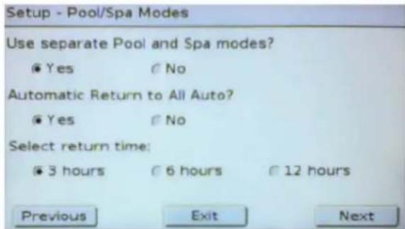
11) If you are operang automatac valves (motorized) to change between your swimming pool and spa, select YES. You will then be asked to set your 'AUTOMATIC RETURN TO AUTO' funcon, we recommend that this feature be set to 'YES'. You are then able to set the return me and choose between 3, 6, or 12 hours. This funcon will enable the system to automacally revert back to the preset mers if a product has been le in the manually on posion.
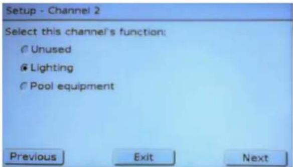
12) Next you must congregate the appliances on each channel of the controller. Start with channel 1 where you will be given the opsons of Unused, Lighng (if congured), Pool Equipment, Controlled Heater Power (if congured) and Solar (if congured). Select which function applies to the equipment connected to the power outlet labeled channel 1.

i. UNUSED – select this opon if channel is not being made acve.
ii. LIGHTING OPTION – select which lighng zone this channel's lights belong to. If this opon is not available, return to step 5. All lighng zone names that have been previously programmed will appear for selecon in this window.
iii. POOL EQUIPMENT – select the name/purpose of the equipment connected to this channel. If an appropriate name cannot be found there is the ability to select 'Custom' where you can create your own name for the channel.

If Filter Pump is selected, you will be given the opon of selecng if a variable speed pump is installed. Only select Yes if the variable speed pump ed is an AstralPool eVo range pump and it is connected via an RJ12 data cable. Variable speed pumps from other manufacturers are not compatible with the Viron Connect controllers.
iv. CONTROLLED HEATER POWER OPTION – select this opon if you are operang a non AstralPool gas heater or a heat pump. This funcon will allow you to turn power on and o to your heater through the heang menu.
v. SOLAR OPTION – if you have congured the controller to operate solar with an independent pump, select this opon.


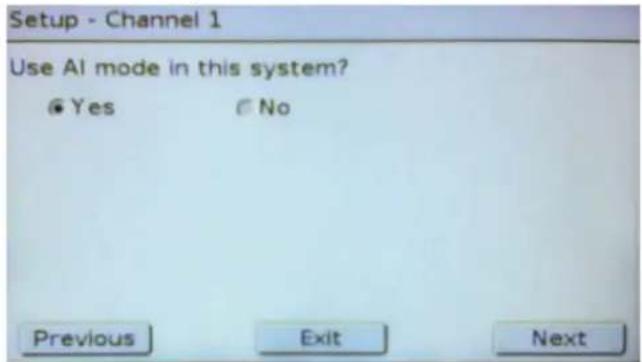
13) Once you have selected the funcon of the channel, you need to advise if you would like to control this channel via a mer. When using a channel for Iter pump utilizing an Astralpool chlorinator in Al mode conguraon, you will now be asked if you want to acvate this funconality for this mer.
14) Repeat step 12 for each additional channel you want to allocate a product to.
15) If you have selected a Genus gas heater and variable speed pump, you will be asked for a minimum 'Heater On' speed. This seng will dictate the speed your pump will operate on when the heater is in the 'ON' seng (this is dierent to when the heater is actually running). This speed should be set to ensure your gas heater is receiving sucient water to acvate the pressure switch.
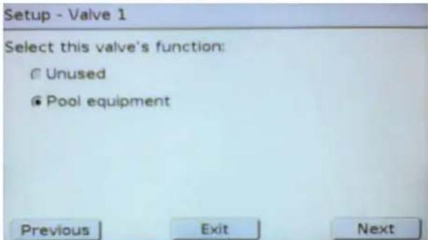
16) Once you have completed the channel allocaons you can program the operaon of the 2 auxiliary valves. These valves operate independent of all other controls and can be used for solar, water features, draining your pool or any other use that you would normally have to control by a manual valve.
17) Depending on prior sengs you may be asked if Cleaning Interlock and Heat Demand are required. Cleaning interlock prevents your Inoor cleaning system acvang without the Itraon pump operang and also prevents it operang when the system is in Spa mode. The Heat Demand will, if acvated, sample the temperature of the water each hour during a programmed period. If the water temperature is below the set point, the heater will be acvated and will connue to operate until temperature is achieved.

18) If you have a compatible AstralPool salt chlorinator or ORP/PH controller, you can use the touchscreen of your Viron Connect to view the set points and the actual readings (readings on ORP and pH only). Note: You can select either Chlorine or ORP – you cannot select both. Use Chlorine seng for salt chlorinators and ORP for systems using an ORP probe.
19) You will now be asked if customisable switches are required. This funcon allows automaon such as 'C-Bus' systems to control two funcons of the connect system only – A 'Favorite' and 'All Auto', via I/O signal. The default seng for this funcon is set to 'No'.

20) A nal summary screen will show the current sengs for the controller. If correct, select Exit, otherwise select 'SET UP WIZARD' to start the process again or ulize the 'JUMP TO' funcon for specie seconds.
Secon 8. Wireless Conguraon / Setup
8.1 If a wireless link system is to be installed, you will need to complete the conguraon below with all components at the same point. Note: Linking of the 2 transceivers by cable is only required during the conguraon process and allows the user to manually assign a new security passcode to their system.
8.2 Connect your wireless transceivers (2 of), your touchscreen controller, and the touchscreen power adaptor together as shown in diagram below.

flowchart
graph LR
    A["Touchscreen"] --> B["Data Cable (RJ12)"]
    C["Touchscreen Transceiver"] --> B
    D["Equipment Transceiver"] --> B
    E["Power Pack"] --> B
    B --> F["24V supply"]
8.3 Go to the 'Setup' opon from the main menu then select 'Congure Wireless'

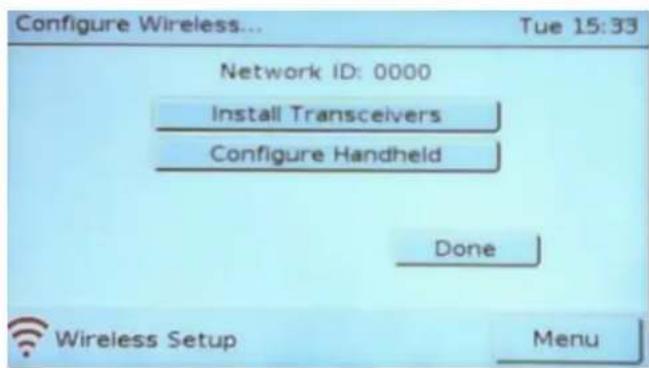
8.4 Use the password '1234' to enter the wireless conguraon menu. The current Network ID will be shown on the screen along with the open to 'Install Transceivers' and 'Congure Handheld'. Select 'Install Transceivers'
8.5 Select 'Install Fixed Transceivers'

8.6 Enter in a Network ID number. This number is a unique code that your wireless link will operate on. Use a code such as the last 4 digits of your phone number to try and avoid conict with other wireless systems in your area. To enter the new code, rst select 'Clear' then enter the number.
8.7 Once equipment is linked as shown above, touch select on the screen. The touchscreen will now send the new ID number out to your transceivers. Once 2 Transceivers have been updated, select the next option from the screen.

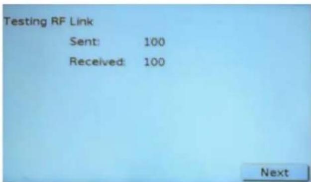
8.8 Posion transceivers in the approximate posion they are to be installed. From the menu, select 'Test Link' to test the strength of the wireless link between transceivers. 100 packets of data will be sent, if less than 100 are received, reposion the transceivers to achieve a 100% result. The system will not work without receiving a 100% sent and 100% received link.
8.9 If you are connecng a handheld (RF) remote to the system also, use the 'Congure Handheld' opon.

8.10 Your RF remote control has 8 outputs which can be programmed to operate any function of Viron Connect controller. Possible programming opons are;
the
1) Favourite sengs;
i. You can program any of the 8 channels to acvate a Favourite seng. This will allow you to have channel 1 as 'Dad's Spa' where the water is at 35, spa jets running and blower on and then have channel 2 as 'Mum's Spa' where the water is at 38, only gentle water ow and the garden waterfall is trickling in the background.
2) Control of pool/spa equipment;
i. You can assign dierent channels to each of the 3 speeds of your Viron eVo series pump.
ii. Allocate a specific piece of equipment such as a blower or waterfall to come on.
i. Nominate a channel to switch all equipment back to Auto. With one buon push all manual changes you have made will be put back to the pre-programmed automat cosion and the mer sengs will take over your system again.
4) Auxiliary valve control;
i. Turn your auxiliary valves on/o or Auto.
5) Lighng control;
i. With a Delta lighng system installed, you can use your remote to toggle between on and o or cycle between colours.
ii. With any brand of lighng you can program lights on or assign lights to a favourite seng.
6) Heater control;
i. Toggle between On/O on your heater.
Secon 9. External Heater Control (non-Genus)
9.1 If a non AstralPool heater is installed or a non Genus compliant heater (such as AstralPool heat pumps), the Viron Connect system can be congured to operate and control the heater from the touchscreen. If you have an AstralPool compliant gas heater installed, do not proceed with the following steps.
9.2 One channel of the Viron Connect controller must be allocated to Controlled Heater Power. This can be any of the channels 1 through 8. This channel will now be acvated and controlled thermostacally and will only turn on when the set temperature is higher than the water temp.
9.3 To operate this feature, you must purchase a Viron Connect Temperature Sensor Kit. This can be purchased through any AstralPool dealer.
9.4 To install and operate an external heater;
i. Proceed through Touchscreen installaon setup (Section 7 of this manual) and at point 8, select No to Genus heater and Yes to use relay board for temperature sensing.
ii. Connue through setup unl you are asked to set up the channel you are using for controlling the heater. For the channel funcon, select 'Controlled Heater Power'.
iii. Connue through remaining installaon setup.
iv. The temperature sensor for the controller must be installed in the system plumbing prior to the heater. The sensor kit is supplied with a 50mm PVC connecons to allow easy installaon. The sensor probe must be plugged into the Viron Connect controller in the entry port labelled water temperature, located directly next to the RJ12 data ports. Note: If the solar feature of the Viron Connect system is being used, you cannot operate the external heater funcon. Please contact AstralPool for further advice if this situaon arises.
v. For heaters supplied with a 10A cable, plug the appliance into the corresponding channel of the Viron Connect (channel that was nominated 'Heater Power'). For appliances rated at 15A use channels 7 & 8. For appliances rated in excess of 15A (such as heat pumps), an electrician will be required to congregate a relay/contactor setup to allow correct operation.
vi. Set the temperature on the heater thermostat to its maximum seng. Once congured the Viron Connect will control the temperature making the thermostat on the heater redundant.
vii. On the Viron Connect touchscreen, select the 'Heang' icon from the main menu. You can now select heater On or O and adjust the temperature up and down. Once temperature is achieved, the Connect controller will cut power to the heater to prevent any further rise in temperature.
Secon 10. Standard Solar control – operang a motorized valve
10.1 During Installaon select connect inbuilt, the Connect 10 will ask if the Filter pump is required to run when the solar is on. If you want to use valves to divert water to the solar collector (instead of a separate pump) you need to answer Yes to this.
10.2 Later in the set up menus you are asked what funcon you wish to assign to the motorised valves: 'Nothing, Pool Equipment or Solar'. Select solar for one of the valves will map that valve to the solar controller.
10.3 If the liter pump isn't running and the solar calls for heat, the liter pump will start and the motorized valve will turn to divert water to the solar collector.
10.4 If the Iter pump is already running just the valve will turn.
10.5 As previously outlined, if you answered no to using Iter pump for solar, then a channel will be available for allocaon. You will then be given the opon to acvate this channel as solar when programming channels 1 – 8. This basic solar funcon then turns the channel on/o when solar gain is called for.
Secon 11. Touch Screen Installaon Instrucons
Plasterboard Recessed Installaon
CONTENTS
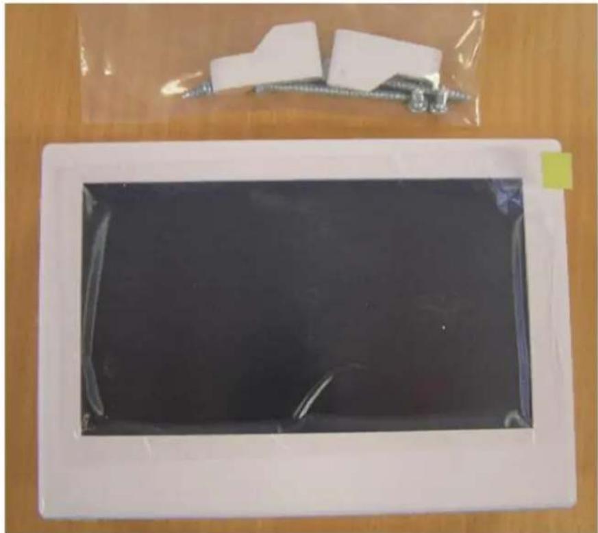
The touch screen is supplied as a complete unit with a mounting base for Solid Walls and mounting arms for Plasterboard/Drywall hollow walls. The accessory plastic bag holds 2 mounting arms, 2 screws for the mounting arms and 4 screws for mounting to the solid wall base.
natural_image
Top-down view of a rectangular electronic device with black screen and plastic components on wooden surface (no visible text or symbols)The casings can be disassembled using a screwdriver as shown:
Figure 1 Secon 11. Touch Screen Installaon Instrucons cont.
To remove the touchscreen from the touchscreen backing panel, use a at blade screwdriver in the slot as shown. Whilst holding the front of the screen, li the tab with screwdriver and angle away unl a gap is created and a small ‘click’ is heard. You will then be able to simply pull the backing panel away from the screen

natural_image
Close-up of a white plastic mechanical component with internal cutouts and a metal tool inserted (no visible text or symbols)
natural_image
White rectangular electronic device with a dark screen and cable, no visible text or symbolsSecon 11. Touch Screen Installaon Instrucons cont.
For Flush Mounting on a Plasterboard or Drywall type wall
The first step is to trace the hole shape onto the wall. To do this you can use the Solid wall Mounting Base as a template.
Trace around the inside as shown except where the circled cut outs are. Just go straight across these cut-outs.

natural_image
Close-up of hands holding a white plastic enclosure with a blue pen inserted, showing a red circle highlighting the interior (no text or symbols visible)
Secon 11. Touch Screen Installaon Instrucons cont.
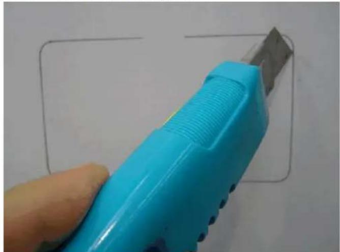
Cut out the shape. NB the corners can be cut out square.
natural_image
Hand holding a blue and silver flatton tool against a white background, with a simple grid line drawn on the wall (no text or symbols visible)
natural_image
Solid dark rectangular shape with a lighter gradient fill, no text or symbols visible.Now the Mounting arms need to be fitted to the screen back.

natural_image
Close-up of a metallic screw with a white plastic clip attached, against a plain background (no text or symbols visible)For a standard thickness wall the mounting arms are fitted as shown:
Secon 11. Touch Screen Installaon Instrucons cont.

natural_image
Close-up of a white plastic clamp or clip with a coiled spring and metal contacts (no text or symbols visible)
natural_image
Close-up of a white plastic clamp bracket with metal screw and handle (no text or symbols visible)For a thick wall, turn the moung arms around as shown:
Connue to screw the moung arms down unl the clamp distance is slightly bigger than the wall thickness.

natural_image
Close-up of a white plastic electrical outlet with red and blue arrows indicating directional movement (no text or symbols)Turn the screw an clockwise so that the moung arms fold into the Screen Back to enable it to t into the wall cut-out.
Secon 11. Touch Screen Installaon Instrucons cont.
When the screws are ghtened, they will swing out to mount to the wall.

natural_image
Close-up of a white plastic electrical enclosure with mounting holes and internal components (no text or symbols visible)Feed the communicaons cable through the rear hole, t the Screen Backing panel into the wall (Note that the TOP marking should be at the top), then ghten the screws

natural_image
Interior view of a white plastic enclosure showing internal components and a cable (no text or symbols visible)Clip the screen back in to nish installaon.

natural_image
Close-up of a person's face in a blue shirt, partially obscured by hands (no visible text or symbols)Secon 11. Touch Screen Installaon Instrucons cont.
Surface Wall Mounng
To mount on a solid wall where it is too difficult to recess the screen into the wall, use the Surface Mount base plate provided. Fit the Screen Backing panel to the solid Wall Mounng Base, and screw into each corner using the 4 small screws provided.

natural_image
Hand holding a white plastic enclosure with internal compartments and mounting holes (no text or symbols visible)The top assembly can then be screwed to the wall using the 2 holes shown below. (Note the orientation of the TOP as shown in large circle).
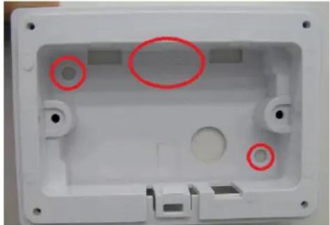
natural_image
White plastic electrical enclosure with two red-circled holes, no visible text or symbolsSecon 11. Touch Screen Installaon Instrucons cont.
Once this is mounted and all screws fastened, the Touchscreen can be clipped on in the same manner as the ush mount. The nished unit:

natural_image
White rectangular electronic device with a clear glass lid, placed on a wooden surface (no visible text or symbols)Secon 12. Custom Switching (from external source)
10.1 The Viron Connect controller has the ability to accept two external switching inputs that allow for the operaon of a 'Favorite' seng. The switching is controlled through a momentary pulse signal which will turn the selected 'Favorite' on. A repeat pulse will re-conrm the favorite is to be on, it does not turn the 'favorite' o. To return the system back to normal, the second custom switch needs to be set as 'All Auto'.
10.2 For most installaons using this feature the set up will be; CUSTOM SWITCH 1 - This will be programmed as one of the owner's 'FAVOURITE' funcons. CUSTOM SWITCH 2 - This will be programmed as 'ALL AUTO'.
You cannot use CBUS to operate all features of the Connect 10. Temperature control, mers etc must sill be operated through the touchscreen.
10.3 To connect to the custom switches;
i. A 2 wire cable (low voltage) needs to be run from the named terminals on the Viron Connect back to the external controller (CBUS or other home automaon system)
ii. The switching terminals require a momentary pulse of an open/close contact. Note: the external controller must not supply any voltage back to the Viron Connect.
iii. In the Touchscreen installaon setup (Secon 7) when prompted select Yes to acvate the use of external custom switches.
This document applies to all versions of the Connect 8 and Connect 10.

Installation of the wiring for this feature should only be performed by a licensed electrician or professional pool technician. Installation will require the removal of protective covers, creating a risk of electrocution. Installation should only take place with the power removed and isolated from the device.
The information and processes in this manual must be followed exactly. Failure to follow warning notices and instructions may result in property damage, serious injury or death. Improper installation and/or operation may void your warranty.
Overview
The Customisable Switches are a feature of the Connect system that allows an external device to interact with and control the Connect system. The external device might simply be a manual switch, or could even be a home automation system.
Two inputs are provided in this feature. The first input is used to activate a Favourite of your choosing; the second input is used to return the system to either 'All Auto' or 'All Off' at your discretion.
Physical Specification
Each of the two customisable switch inputs is provided by one of two 2-way screw terminals on the Connect. The terminals are located above the bank of RJ12 communications terminals, beneath the main protective cover.

Ensure that mains power is disconnected and isolated from the device before removing any covers.
The inputs are "voltage free contact" type, meaning they are expecting to be wired to the contacts of a switch or relay. Wire 1 of the terminal is the "signal" wire, and has a weak pull-up to 5V. Wire 2 of the terminal is the "common" or "ground". When the external contacts make, they short the signal wire to the common wire.
At no time should any external voltage be applied to either wire of the terminals.
It is possible to use an "open collector" switch, provided attention is paid to the polarity of the wiring.
Acceptable connection methods are shown in the following diagram.

flowchart
graph TD
    A["Internal"] --> B["Signal 1, Common 2"]
    B --> C["External Wiring"]
    C --> D["Relay"]
    E["External Wiring"] --> F["Signal 1, Common 2"]
    F --> G["Push-button"]
    H["External Wiring"] --> I["Signal 1, Common 2"]
    I --> J["Open-collector output"]
When the external contact closes and the two wires are shorted together, the input is considered "active". When the contacts open, the input is considered "inactive". Debouncing of the input state is provided internally; in order to correctly register as active or inactive, the contacts should stay open or closed for at least 0.5 seconds.

Configuration
Please consult the Colour Touchscreen manual for information about how to configure the Custom Switches. This manual is available online from AstralPool.
Secon 13. Service Mode Operaon
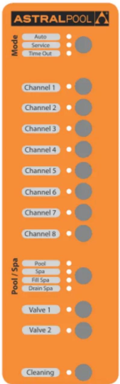
9.1 If control of the Connect system is required from outside the house, all equipment can be operated from the service panel inside the main electrical control box. This funcon would be used when waning to manually operate any channel via a simple ON/OFF buon press, for example performing a backwash or manually vacuuming the pool. Select 'Service Mode' using the top buon on the service panel, the green light will now be illuminated next to 'Service'. All auxiliary funcons can now be controlled from the box while the internal touchpad is temporarily disabled.
If you want the manual operaon selected to run for a period then revert back to the touchscreen operaon, place the control panel into the 'Time Out' funcon. The 'Time out' funcon will now run for one hour.
Selecng Auto mode will place the touchscreen back into 'All Auto' status.
If you pool has experienced heavy use or has been directed by storms, you can acvate a special cleaning cycle from the Viron Connect service panel (if system is congured with cleaning – see secon 7). Ensure the system mode is in Auto then press the buon allocated to Cleaning. Your system will now operate the cleaning and Itraon pumps for 1 hour then revert back to normal operaon.
Secon 14. Viron Connect 10 Funconality
2 x 10A constant power outlets. Can be used for AstralPool gas heaters, lightng systems and Chlorinators which rely on constant power for operaon (usually controlled via data cable). Items which require turning ON/OFF or TIMER funconality should not be connected to these outlets.
6 x 10A switchable outlets. These are channels 1 - 6 as programmed from the Viron Connect touchscreen.
2 x 15A switchable outlets. These are channels 7 - 8 as programmed from the Viron Connect touchscreen.
4 x Valve actuator sockets. Two actuators are allocated to the pool/spa funcon of the controller and turn simultaneously. The 2 additional actuator valve sockets can be programmed to run any funcon required.
Touchscreen controller and 1 x 20m RJ12 cable.
2 x momentary input contacts. These contacts can be used for conncon to external home automaon systems. The funcon of the switches can be programmed by the operator but these are an ON switch only. A second signal will not switch the funcon o, it must be turned o at the touchscreen or have the second switch programmed to an 'All Auto' seng.
Connect In-built solar funcon. Basic solar funcon that can be programmed to operate its own pump or drive an actuator to divert water. Service mode. From the external control box the Connect 10 can be put into 'Service Mode' which provides operaon of all 8 channels plus 'Pool/Spa', 'Valve' and 'Cleaning' features.
Oponal accessories:
- Touchscreen wireless transceiver (10016) and Equipment side transceiver (10017) allow for retrot installaons into houses without needing to run a cable between the Connect Controller and the touchscreen. The Equipment side Transceiver links directly to the connect controller box and can be installed in the equipment room or externally to achieve the best RF signal. The transceiver at the touchscreen end has a 24VDC powerpack which needs to be connected to mains power and linked directly to the touchscreen via an RJ12 cable.
- Waterproof RF Handheld remote (15205). Must be used in conjuncon with a 10019.
- The RF remote can be congured or programmed to allow the 8 buons to operate any 8 features of the Connect system. It may also be programmed to operate 'favorite' menu sengs, turn a valve or return system to 'All Auto'.
- Viron Connect 10 Temperature and solar sensor kit (520146) can be used when operang an AstralPool heat pump or another manufacturer's heater. This is also needed when operang the solar heang onpon from the controller.
- Viron Connect 10 Solar modulator lead (15211-3mtr), (15212-20mtr), (15213-50mtr) to be used in conjunction with solar heang onpon. These are to be installed as roof temperature sensors.
- Valve actuator (10945) must be used in conjuncon with a Permaseal valve.
- Internet Gateway (10030) – To enable mobile control over pool and spa controller via internet or mobile APP.
- RJ12 data cable (10910-3mtr), (10925-10mtr), (10926-20mtr), (10927-50mtr).
Section 15. Troubleshooting
| SYMPTOM | RESOLUTION |
| Equipment not activating on time clock | Check All Auto selected from Home menuCheck timer programmingCheck for timer periods/days crossing over |
| No power to touchscreen | Check isolation switch is onCheck safety switchCheck RJ12 cable connections |
| Touchscreen not activating channels | Check “Service Mode” not enabledCheck SYSTEM / LOCAL connectionReset power to control systemCheck RJ12 cable connections |
| Wireless link not responding | Reset wireless configurationCheck power is available to adaptorMove wireless transceivers to a new location |
Secon 16. Equipment Outlet Names
Record what equipment is plugged into the Equipment Centre. This will enable you to name each channel when you set up the touch screen control
Example:
Channel 1 Viron 3 speed Pump
Channel 2 Arc underwater Light
Channel 1
Channel 2
Channel 3
Channel 4
Channel 5
Channel 6
Channel 7
Channel 8
Motorised Valve 3
Motorised Valve 4
Part Two: Installing the Internet Gateway and Smart Phone/Tablet App
The Internet Gateway is an oponal purchase that allows the Connect 10 Pool and Spa Controller to connect to the internet, via a Wi-Fi or Ethernet connection, to a home Router. Downloading the free App 'connectmypool' and correctly seng up all equipment will allow the pool owner to control the pool and spa from their Smart Phone or Tablet.
The installaon of the Connect 10 Internet Gateway is a simple three stage process. Follow these instrucons carefully and you will have instant access to control your pool and spa every me, no maer where you are: in your house, on the way home from work, or on the way to your holiday home.
Stage 1: install the hardware and connect to your home Wi-Fi or internet Router.
Stage 2: register your pool owner's details and any other authorised users at www.connectmypool.com
Stage 3: Download the Connectmypool App from the App store or Android Store
Stage 1 – installing the hardware and connecng to your home Wi-Fi or Internet Router.
The most common way of connecng the 'Internet Gateway' (Part # 10030) to the internet via a home Wi-Fi conneccon is shown below. Wherever possible though, it is always recommended to connect via Ethernet cable as seen in opon 2. Use of opons 1 & 3 are recommended for retrong control system to exisng pool system, or where cable installaon is impossible. If area is known to have poor Wi-Fi or recepon quality, then cable installaon is highly recommended.
Opon 1 – Wi-Fi to Home Modem connected to Broadband Internet Connecon.
Connect RJ12 cable from controller to 'Internet gateway'. 'Internet gateway' will connect via Wi-Fi to home router when in signal range.
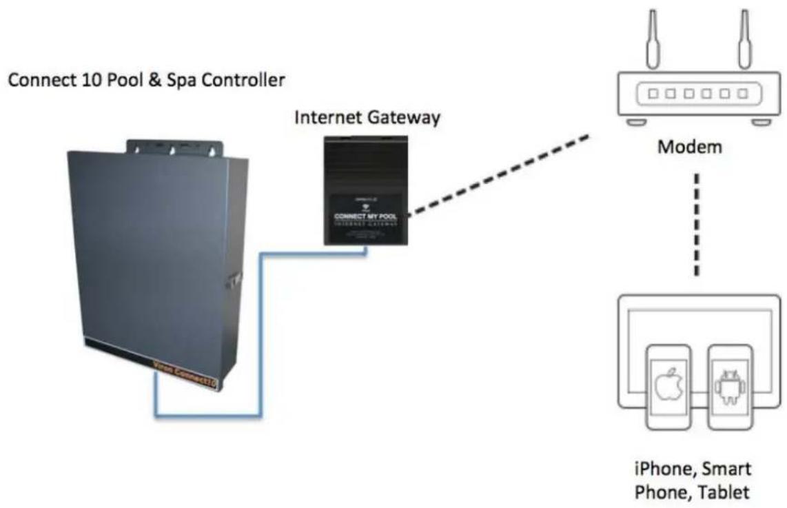
flowchart
graph TD
    A["Connect 10 Pool & Spa Controller"] --> B["Internet Gateway"]
    B --> C["Modem"]
    C --> D["iPhone, Smart Phone, Tablet"]
Opon 2 – 'Internet Gateway' to Home Computer via Ethernet cable to Home Model Connect RJ12 cable from connect controller to 'Internet gateway', then Ethernet cable directly to router

flowchart
graph LR
    A["Connect 10 Pool & Spa Controller"] --> B["Internet Gateway"]
    B --> C["Modem"]
    C --> D["iPhone, Smart Phone, Tablet"]
    B --> E["Computer"]
    E --> F["Desktop with connectivity lines"]
Opon 3 – FM wireless transceiver to 'Internet Gateway' to Home Modem
Connect RJ12 cable from Connect controller to 'Equipment side transceiver'. Connect 'Touchscreen side transceiver' via RJ12 cable to 'Internet Gateway' – This will establish a wireless link between transceivers and then communicate via Wi-Fi to the home router (when in range).

flowchart
graph TD
    A["Connect 10 Pool & Spa Controller"] --> B["Transceiver Part # 10016"]
    B --> C["Transceiver Part # 10017"]
    C --> D["Internet Gateway"]
    D --> E["Modem"]
    E --> F["iPhone, Smart Phone, Tablet"]
In all cases the internet conneccon must be permanently connected to a broadband internet service. (The Internet Gateway cannot be connected via a mobile 'hotspot' or similar).
Prior to commencing the installaon, the locaon of the home Wi-Fi transmier (or host computer if using an Ethernet conncon) must be determined along with the Wi-Fi Network name and Wi-Fi Password or Passcode.
Each Internet Gateway is labelled with its own unique Internet Gateway Serial number. Also within the packaging of the Internet Gateway is the unique Internet Gateway Passcode. This label is located on the Internet Gateway itself, not on the packaging. This label will be required to register the Internet Gateway onto the internet and needs to be retained by the pool owner.
The home Wi-Fi signal strength can initially be observed using a mobile phone as a guide. As a reliable conncon is essenal, it is important to nd a posion that has a strong Wi-Fi signal. The Internet Gateway has a reset buon in its base, as well as LEDs that will assist when determining the nal posion for installaon. Once an approximate posion is determined, the 'Internet Gateway' Can be connected to a loose RJ12 cable unl the locaon with best signal strength is found.
Base (underneath) of Internet Gateway

Aer connecng the Internet Gateway to the Pool System the Home Wi-Fi can be congured.
This is achieved using the Touch Screen
- On the Touchscreen, go to 'Setup'.
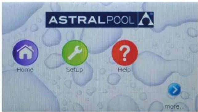
- Use the arrows to scroll pages, and then press on the 'Internet Gateway' buon.
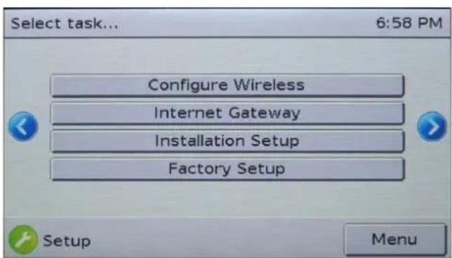
- You are now shown the main Internet Gateway Diagnoscs page. This page allows you to conjure the Wi-Fi sengs. On this page the Internet Serial Number is also displayed. If the serial number is shown as '???', then the Touchscreen cannot communicate with the Internet Gateway. (Refer to troublesomeong before connuing)
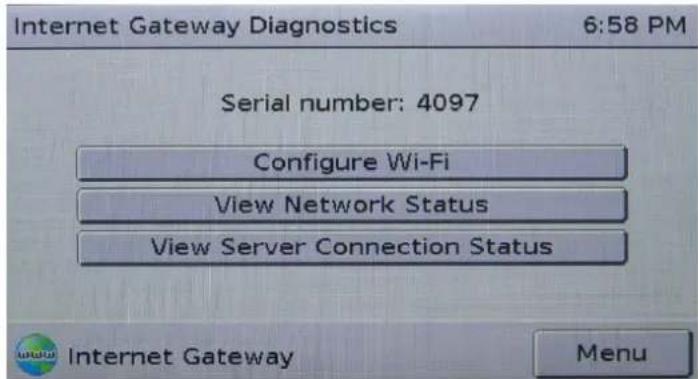
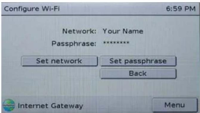
- You are now shown the 'Congure Wi-Fi' page. This page allows you to conjure the Wi-Fi sengs.
-
From this screen, press 'Set network'. Use the Backspace buon to remove the 'Your Name' text and then use the keyboard to enter the name of your home Wi-Fi conncon. Similarly use the 'Set passphrase' key to set the passphrase/password of your home Wi-Fi conncon. Network names and Passphrases are case sensitive- make sure you enter them correctly and exactly otherwise system will not connect to network.
-
From the ‘Congure Wi-Fi’ screen, press the ‘Back’ buon to go back to the ‘Internet Gateway Diagnosis’ screen and then press the ‘View Network Status’ buon to check the signal strength. It will take a few minutes to connect to the Wi-Fi, but at the end of the conncon process the screen should show that the conncon is Enabled, Inialized and Linked. It should also show the home IP address and the Wireless Signal strength. (Wi-Fi) The Wi-Fi signal strength should be 29 or greater. If it is less than 29 the Internet Gateway should be moved closer to the Home Wi-Fi source to ensure reliable and stable conncon.
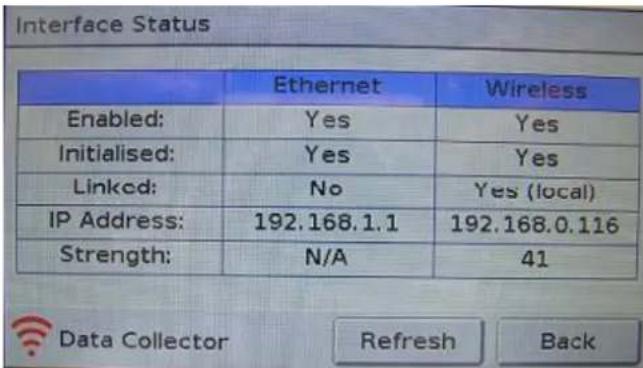
If the Wi-Fi signal strength is 29 or greater, the Internet Gateway can be mounted in posion.
Stage 2: Registering 'Pool Owner' and authorised 'Users' of the Pool App
In order to acvate the connectmypool App you must register the pool's owner. The Pool Owner will have authority to access applicable funcons in the Viron Connect 10 Pool and Spa controller and also delegate access to other users – which may be other members of the family or your pool service technician.
It is important that the actual Pool Owner is the registered Pool Owner. This ensures that the Pool Owner and his family are given access to the connectmypool App and control of the pool and NOT the installer or service technician.
To register to be a Pool Owner and use the Pool App, owners need to have a valid email address and to have purchased an Internet Gateway (Part #10030) which comes with a unique serial number and passcode.
Registraon needs to be done on a desktop or Laptop computer (ie not a mobile phone or tablet) and is initialized by vising hp://connectmypool.com in your website browser.
The following screen will then be visible:
ASTRALPOOL

Login Here

Username/Email:
Password:
natural_image
Two horizontal rectangular bars with small red dots at the top and bottom (no text or symbols)Remember me
Login

Clicking on 'Register Here' will then bring up the User Registraon page:
All elds in the User Registraon need to be lled out. The email address supplied must be a valid email address as an email with a link in it will be sent to this address.
The Password is used by the Pool Owner to access the App.
In a laer process, other users can be allocated access to this pool. They will be able to use their own password to access the App.
Registration
User Registration
Pool Registration
First Name
Last Name
Username/Email
Password
Confirm Password
Next
Aer this is lled in and 'Next' is pressed, the Pool Registraon page is shown:

The ‘Internet Gateway’s’ unique Serial Number and Passcode must now be entered. This is found on the registraon scker inside the box and must be kept by the pool owner. This informaon has been included as an adhesive label for convenience to consumer and also for security reasons.

The Pool Name that is entered on this page will be displayed on the App. If you plan to be able to log into more than one pool, then the name should describe which pool you are waning to control.
e.g. For this registraon you may name the pool ‘Jones Home’ and for a second Pool Registraon it may be named ‘Jones Beach’. Once your rst Pool has been registered, the second pool can be entered later by logging onto your exisng account, (using a desktop computer) through the ‘Sengs’ tab. And ‘Add Pool’. The Pool Street address and Post Code is used to identify the Pool Locaon and provide weather informaon for the area around the pool.
Aer pressing the 'Submit' buon above, an email should be delivered to your Email Address. This email will contain a link that you need to press to conrm and complete the registraon process.
NB. Some providers may interpret this email as Junk. If you don't receive an email within a few minutes please check your Junk email folder.
Aer compleng registraon, it is necessary to log out. Wait 10 minutes and log back in with the user name/email and password you created. The system should now have congured itself and you will have access to the programming that has already been completed on your Connect 10 touch screen.
Aer the system has congured itself you can proceed to add more users to your pool if required. This can allow all your family members with a Smart Phone or Tablet to also access the pool and control remotely, or possibly allow your pool technician to monitor your pool water chemistry.
To let additional people access your pool controller press 'SETTINGS', then 'User List', then 'Add User'.
![FRIDAY, DECEMBER 06 2013 Pool SETTINGS WELCOME LOG OFF Profile Settings User List Add Pool Replace Data Collector Announcement ASTRALPOOL Home Users List Add User You have currently not delegated access to you pool. Please click [Add User] to allow another person access to your pool.](/content/2026/05/931535/images/9dd3a19866f4bf491be93bc21ee9fba525124fcefce51c18bb3c63caef29e4ba.jpg)
Aer pressing 'Add User' you will be prompted to enter the new user's name and email address along with their password.
Once a User is added, their ability to access dierent features can be setup using the 'Screen Conguraon' buon. (On the 'User List' page).
This feature allows the Pool Owner to grant user access to specific features only. For example if the pool has heang, the pool owner can restrict a user from changing the temperature etc.
In addition, the new User once added, will receive an email which will require them to 'conrm' their link to your pool and then download the Connectmypool.com app.
In certain circumstances you may wish to give access to service people or guests. They can be added to the User list as above and their access can be deleted later if desired.
Other features on the 'Sengs' page include the ability to add another pool to your App. To do this you need to purchase a separate Internet Gateway and connect it to the new pool. Remember to make the new pool name descripve so that you can easily see which pool you are controlling. (On the App, tapping the pool name will bring up a list of your available pools if you have more than one.
5.0 Start Applicaon and log in.
If the connectmypool isn't running, nd the connectmypool icon on your desktop, and select it.

The applicaon will start. Log in using the username and password that was set up during registraon.
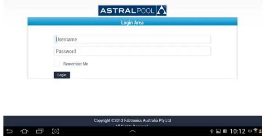
NOTE: You must log out for 10 minutes, then log in using your newly created user name/email and password before the system will congure itself.
Troubleshoong
To conrm that the Internet Gateway is able to connect to the connectmypool servers, follow these steps.
- On the Touchscreen, go to 'Setup'.

- Use the arrows to scroll pages, and then press on the 'Internet Gateway' buon.

- You are now shown the main Internet Gateway Diagnoscs page. This page shows you the serial number of the 'Internet Gateway', as well as allowing you to perform further conguraon or diagnoscs.

If the serial number is shown as '???', then the Touchscreen cannot communicate with the Internet Gateway. Check that the Internet Gateway is plugged in to the pool system, using normal at-cable RJ12 conncon, and that the plugs of the RJ12 cable have the correct orientaon.
- Press the 'View Network Status' buon. This page shows you the status of the two network connecons of which the Internet Gateway can make use. The informaon can be refreshed with the 'Refresh' buon.
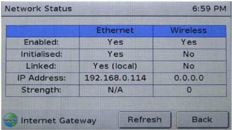
The Internet Gateway can use either wired (Ethernet) or wireless (Wi-Fi) conncon. The status of each is shown in the table.
If the table is lled with '?' , then the Touchscreen cannot communicate with the Internet Gateway. Check that the Internet Gateway is plugged in to the pool system, using normal at-cable RJ12 conncon, and that the plugs of the RJ12 cable have the correct orientaon.
In most cases, the Internet Gateway will only be using one of the two conneccon methods. To conrm that the Internet Gateway has a proper network conneccon, the following is required for either the Ethernet or Wireless conneccon:
- The 'Linked' eld for the appropriate conncon method must be 'Yes'; and,
- The IP address must NOT be '0.0.0.0'.
In the image shown above, the Ethernet conncon indicates that it is operang correctly, whilst the Wireless conncon shows that it is not operang.
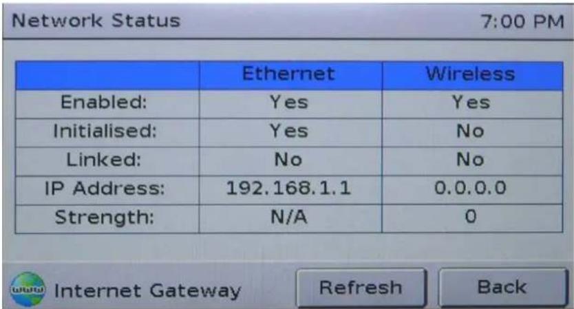
In the image above, the Ethernet conncon is no longer operang correctly, as the 'Linked' eld shows 'No'.
Troubleshoong The Ethernet Connecon
'Inialized' shows 'No'
The Internet Gateway was unable to initialize the Ethernet conncon. Cycle power to the Internet Gateway and wait 1 minute to allow for re-initializaon. If the problem persists, call AstralPool for support.
'Linked' shows 'No'
Check that the Ethernet cable is correctly connected to both the Internet Gateway and the pool owner's home network hub (router).
Check the orange light beside the Internet Gateway's Ethernet conncon; if it is illuminated, the Ethernet conncon is present and there may be a problem with the router or internal security of the home network. Call network support to clarify issue. If network conncon ok and the problem persists, call AstralPool for support on 1300 244 414
Troubleshoong The Wireless Connecon
'Inialized' shows 'No'
The Internet Gateway was unable to inialize the Wireless conncon. Cycle power to the Internet Gateway and wait 1 minute to allow for re-inializaon. Check all conncons and signal strength ok. If the problem persists, call AstralPool for support.
'Linked' shows 'No'
The Internet Gateway was unable to connect to the pool owner's wireless network. Verify that the network name and passphrase have been correctly congured by re-entering them into the Touchscreen. Allow the Internet Gateway 30 seconds to aempt conneccon to the home network before proceeding.
Cycle power to the Internet Gateway and wait 1 minute to allow for re-inializaon. If the problem persists, call AstralPool for support.
IP Address shows '0.0.0.0'
The most common cause is that the Internet Gateway is right on the fringe of wireless range. Try moving the Internet Gateway closer to the pool owner's wireless router, then cycle power to the Internet Gateway to cause re-inializaon. Ideally, the strength should be shown as 29 or greater. If the problem persists, consider changing from Wireless to Ethernet conncon types.
-
Return to the main Internet Gateway Diagnoscs screen by pressing 'Back'.
-
Press the 'View Server Connecon Status' buon. This page shows you that status of the conneccon between the Internet Gateway and the connectmypool server.
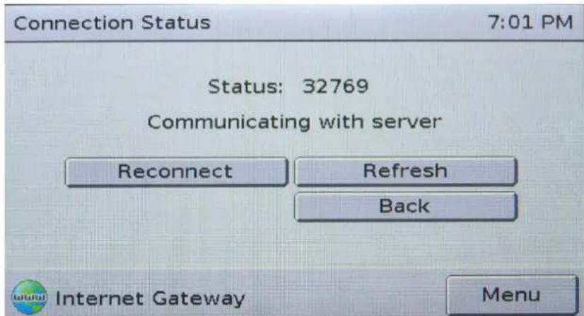
If the status is shown as '?' , then the Touchscreen cannot communicate with the Internet Gateway. Check that the Internet Gateway is plugged in to the pool system, using normal at-cable RJ12 conneccon, and that the plugs of the RJ12 cable have the correct orientaon.
The 'status' eld will show a numerical code and a text explanaon. See the table below for more informaon. The two most common codes you will see are 32769 and 61440. These codes indicate that the conncon to the server is open/closed normally. Other codes may indicate a fault condion, or be 'conncon in progress' codes. If you need to update the informaon on the screen, press 'Refresh'. If you wish to force the Internet Gateway to recommence the conncon sequence, press 'Reconnect'. Note that the internet Gateway will periodically aempt reconnecon automacally (typically 30 seconds, but the pool owner can adjust this through the connectmypool website).
| Code | Text | Meaning |
| 0 | Idle | The IG has not yet aempted to connect to the server. Wait for the IG to automacally connect, or press ‘Reconnect’ to force a conneccon aempt. |
| 32768 | Connecon open | The conneccon to the server is open, but no communicaon has yet been received. If this state persists for more than 30 seconds, please call AstralPool for support. |
| 32769 | Communicang with server | The conneccon is open and the Internet Gateway is communicang normally with the connectmypool server. This is not a fault state; this is normal operaon. |
| 61440 | Connecon closed | The conneccon to the connectmypool server was closed as part of normal operaon. This is not a fault state; the IG will automacally reconnect shortly. |
| 256 | No suitable interfaces ready | The Internet Gateway is unable to connect to the internet because none of its interfaces (Ethernet or Wireless) are operang correctly. Return to the receding troublesomeong steps to conrm that at least one of the network interfaces is operang correctly. |
| 513 | DNS resolve error | The Internet Gateway was unable to determine the IP address (internet address) of the connectmypool server. The most likely cause is that the pool owner's internet conneccon has failed. Verify that the home internet conneccon is sll operang. |
| 769 | Internal error creang local socket | The Internet Gateway has suered an internal error. Cycle power to the Internet Gateway; if the problem persists, call AstralPool for support. |
| 1024 | Connecng to server | The Internet Gateway is trying to connect. If this state persists for more than 30 seconds, call AstralPool for support. |
| 1025 | Failed to connect | The Internet Gateway was unable to connect to the connectmypool server. The most likely cause is that the pool owner's internet conneccon has failed. Try to verify that the home internet conneccon is sll operang. If the problem persists, cycle power to the Internet Gateway. Call AstralPool for further support if required. |
| 61441, 61442, 61443, 61444 | The conneccon to the connectmypool server has been closed due to various errors. One cause is the loss of the pool owner's internet conneccon. Try to verify that the home internet conneccon is sll operang. Press ‘Reconnect’, and wait for the IG to aempt to reconnect to the connectmypool server. If you connue to get these error codes, call AstralPool for support. | |
| Others | There are other status codes that won't be detailed here. If the Internet Gateway gets “stuck” on one of them, call AstralPool for more details. |
Internet Gateway Status Lights
The image below shows the boom view of the Internet Gateway module.
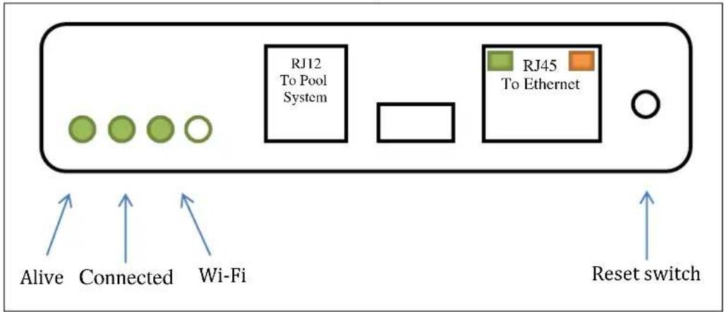
The Internet Gateway has three main status lights.
The ‘Alive’ status light ashes once every two seconds to indicate that the module is powered and operang correctly. The ‘Connected’ status light provides informaon about whether the Internet Gateway is/was able to connect to the connectmyPool servers.
- When this connected light is o, the Internet Gateway has not yet aempted to connect to the connectmypool servers (such as just aer powering up).
- When this light is solidly illuminated (not ashing), then the Internet Gateway is currently connected to the connectmypool servers.
- When this light is ashing, the Internet Gateway is no longer connected to the connectmypool servers. If it is giving a single ash, then the conncon to the servers was closed normally. If it is giving a double-ash, then the conncon to the servers was terminated due to an error.
The 'Wi-Fi' light indicates the status of the wireless conncon. When this light is o, there is no wireless conncon. When this light is lit, it means that the Internet Gateway is properly connected to the pool owner's Wi-Fi network. It will blink briefy when the Internet Gateway is sending or receiving informaon over the wireless network. Please note that this indicator is only giving the status of the local conncon to the wireless network. The status for the conncon to the connectmypool servers is sll given by the 'Connected' indicator.
The Ethernet connector has two in-built indicators. The orange indicator is illuminated when the Ethernet conncon is properly connected to the pool owner's Ethernet network. Please note that this indicator is only giving the status of the local conncon to the Ethernet network. The status for the conncon to the connectmyPool servers is sll given by the 'Connected' indicator. The green indicator blinks when there is data being sent or received on the Ethernet network.
Maintenance of your Controller
Maintenance Schedule: Your new product incorporates moving parts and withstands high velocity water with chemicals in it. Some of these parts will wear in the normal course of use and require regular checks and maintenance. Performing these checks and maintenance will identify parts that have worn and require repair/replacement before further serious damage is sustained. A small amount of regular care and attention to your pool equipment will help ensure long life and trouble free performance.
To protect against extremes of temperature, your unit is vented to allow expensive electronics to cool. Ants and some insects are often attracted to the warmer, dry environment inside the enclosure. We recommend that, with power turned off, you spray a surface insecticide on the surfaces surrounding the control to prevent ant and insect ingress. Repeat every three months or as necessary.
| Timing | Maintenance Check | Service action (if required) |
| Three Monthly | Check for inserts/ants | Turn power off, Spray a surface insecticide on the surfaces around the unit to prevent ant and insect ingress. |
Important note: Regular maintenance is important to ensure long life and trouble free performance of your pool equipment. If unable to perform the maintenance yourself, contact your local AstralPool office who will arrange a trained service technician to perform the maintenance for you.

INST314

sales@astralpool.com.au
www.astralpool.com.au
Fluidra Group Australia Pty Ltd
219 Woodpark Road,
Smithfield, N.S.W. 2164
ABN 087 002 641 965



- Pool and Spa Controller
- INSTALLATION AND
- OPERATING INSTRUCTIONS
- WARNING
- Record your Equipment details here for quick reference:
- Table of Contents
- Secon 1 Overview....5
- Secon 2 Equipment Operaon....6
- Secon 3 Seng the Clock 9
- Secon 4 Timer Programming ....10
- Secon 5 Favourite Programming....16
- Secon 6 Equipment Installaon....18
- Secon 7 Installaon Setup....22
- Secon 1. Overview
- Components
- Basic Operaon
- Secon 2. Equipment Operaon
- Pool & Spa Opon
- Lighng
- Heang (if applicable)
- Solar (if applicable)
- Favorites
- Secon 3. Seng the Time
- Secon 4. Timer Programming
- NOTE : ONCE ALL TIMERS HAVE BEEN PROGRAMMED, ENSURE NO TIMER PERIODS OR DAYS ARE OVERLAPPING BEFORE CONTINUING.
- Secon 5. Favorite Programming
- Secon 6. Equipment Installaon
- Control Box Installaon
- Touchscreen Installaon
- THE TOUCHSCREEN SUPPLIED WITH THE VIRON CONNECT CONTROLLER SYSTEM IS DESIGNED FOR INDOOR INSTALLATION ONLY.
- Appliance Installaon / Connecon - Power
- Appliance Installaon / Connecon – Communicaons
- Secon 7. Installaon Setup
- Touchscreen Controller Setup
- SHOWING LOCATION OF LOCAL/SYSTEM PLUG
- Secon 8. Wireless Conguraon / Setup
- Secon 9. External Heater Control (non-Genus)
- Secon 10. Standard Solar control – operang a motorized valve
- Secon 11. Touch Screen Installaon Instrucons
- CONTENTS
- Figure 1 Secon 11. Touch Screen Installaon Instrucons cont.
- Secon 11. Touch Screen Installaon Instrucons cont.
- For Flush Mounting on a Plasterboard or Drywall type wall
- Surface Wall Mounng
- Secon 12. Custom Switching (from external source)
- Overview
- Physical Specification
- Configuration
- Secon 13. Service Mode Operaon
- Secon 14. Viron Connect 10 Funconality
- Oponal accessories:
- Secon 16. Equipment Outlet Names
- Part Two: Installing the Internet Gateway and Smart Phone/Tablet App
- Stage 1 – installing the hardware and connecng to your home Wi-Fi or Internet Router.
- Stage 2: Registering 'Pool Owner' and authorised 'Users' of the Pool App
- ASTRALPOOL
- Login Here
- Registration
- Start Applicaon and log in.
- NOTE: You must log out for 10 minutes, then log in using your newly created user name/email and password before the system will congure itself.
- Troubleshoong
- Troubleshoong The Ethernet Connecon
- Troubleshoong The Wireless Connecon
- Internet Gateway Status Lights
- Maintenance of your Controller
- INST314
Brand : ASTRALPOOL
Model : Viron Connect 10
Category : Swimming Pool