ProElyo Inverter - Pool ASTRALPOOL - Free user manual and instructions
Find the device manual for free ProElyo Inverter ASTRALPOOL in PDF.
User questions about ProElyo Inverter ASTRALPOOL
0 question about this device. Answer the ones you know or ask your own.
Ask a new question about this device
Download the instructions for your Pool in PDF format for free! Find your manual ProElyo Inverter - ASTRALPOOL and take your electronic device back in hand. On this page are published all the documents necessary for the use of your device. ProElyo Inverter by ASTRALPOOL.
USER MANUAL ProElyo Inverter ASTRALPOOL
User and service manual
SWIMMING POOL HEAT PUMP
PRO-ELYO INVERTER
INDEX
- Description p.3-4
- Specification p.5
- Adjust by-pass kit p.6
- Location and connection p.7-10
- Electrical Wiring p.11-13
- Start-up of the Heat Pump p.14-19
- Parameters p.20-21
- Troubleshooting p.22-24
- Exploded Diagram and Maintenance p.25-31
- WARRANTY p.32-33
Thank you for using PRO-ELYO Inverter swimming pool heat pump for your pool heating, it will heat your pool water and keep the constant temperature when the air ambient temperature is at -10 to 40^

ATTENTION: This manual includes all the necessary information with the installation of your heat pump.
the use
-
The installer must read the manual and attentively follow the instructions in implementation and maintenance.
-
The installer is responsible for the installation of the product and should follow all the instructions of the manufacturer and the regulations in application. Incorrect installation against the manual implies the exclusion of the entire guarantee.
-
The manufacturer declines any responsibility for the damage caused with the people, objects and of the errors due to the installation that disobey the manual guideline. Any use that is without conformity at the gini of its manufacture will be regarded as glorous.

WARNING:
*Please always empty the water in heat pump during winter time or when the ambient temperature drops below 0^ , or else the Titanium exchanger will be damaged because of being frozen, in such case, your warranty will be lost.
*Please always cut the power supply if you want to open the cabinet to reach inside the heat pump, because there is high voltage electricity inside.
*Please well keep the display controller in a dry area, or well close the insulation cover to protect the display controller from being damaged by humidity.
1.1 With your Heat Pump
- Water connection assembly 50~mm (pcs: 2)
-Userandservicemanual - Condensed connection
- 10 meters signal wire
- Waterproof box
-Wintercover - Anti-vibration base (pcs: 4)
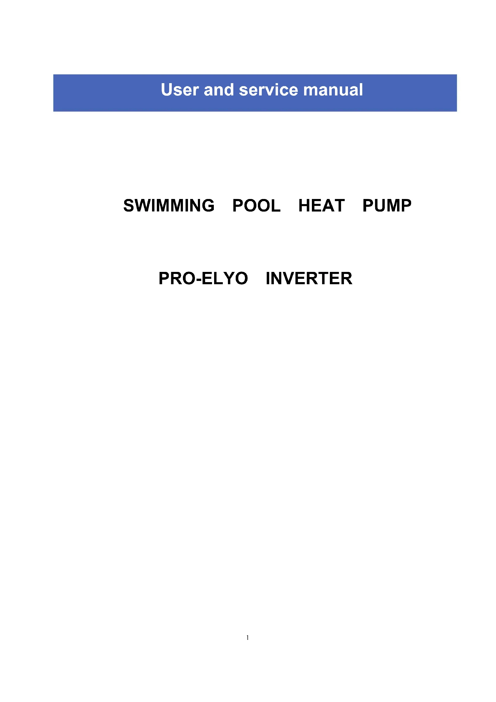
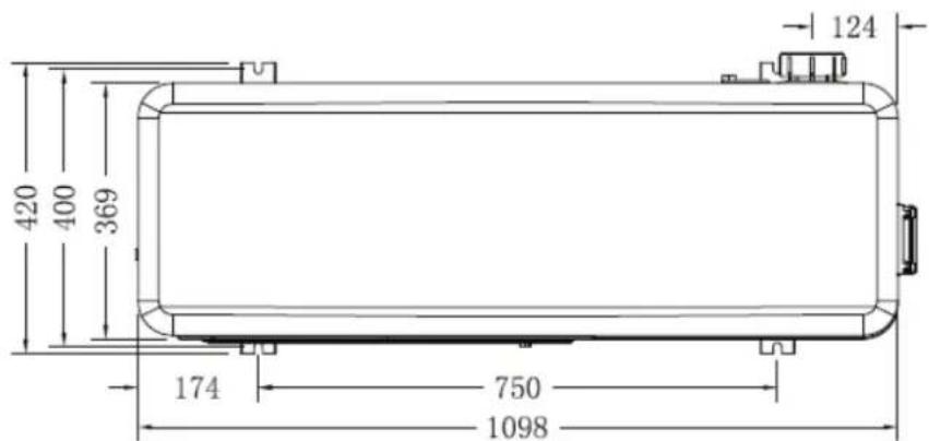
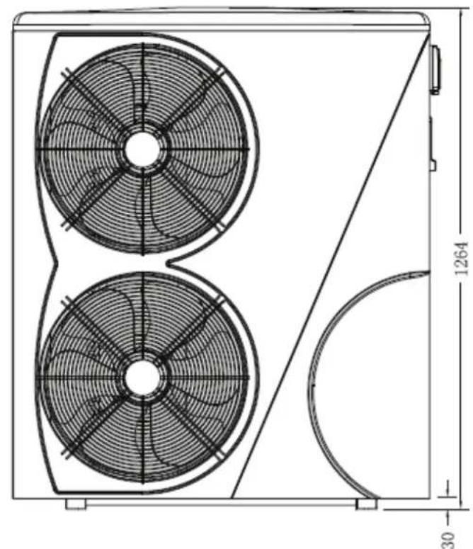
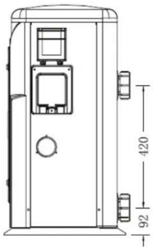
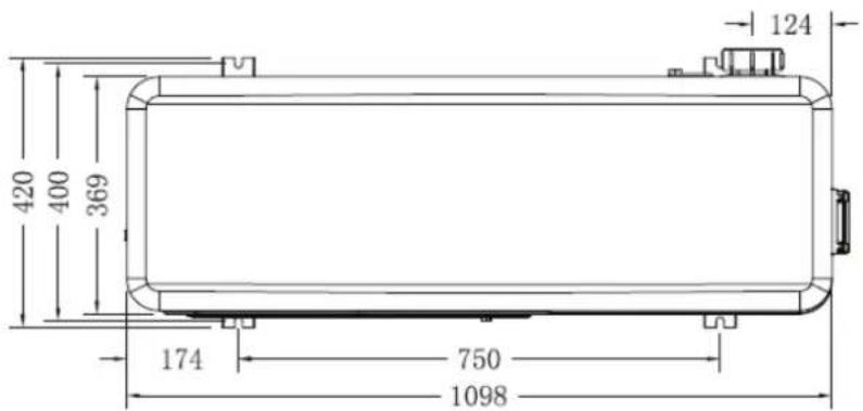
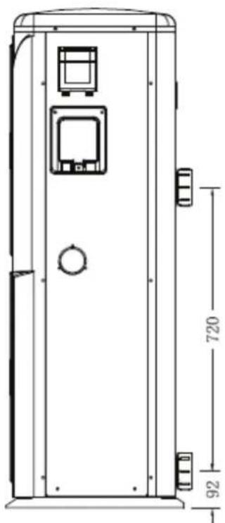
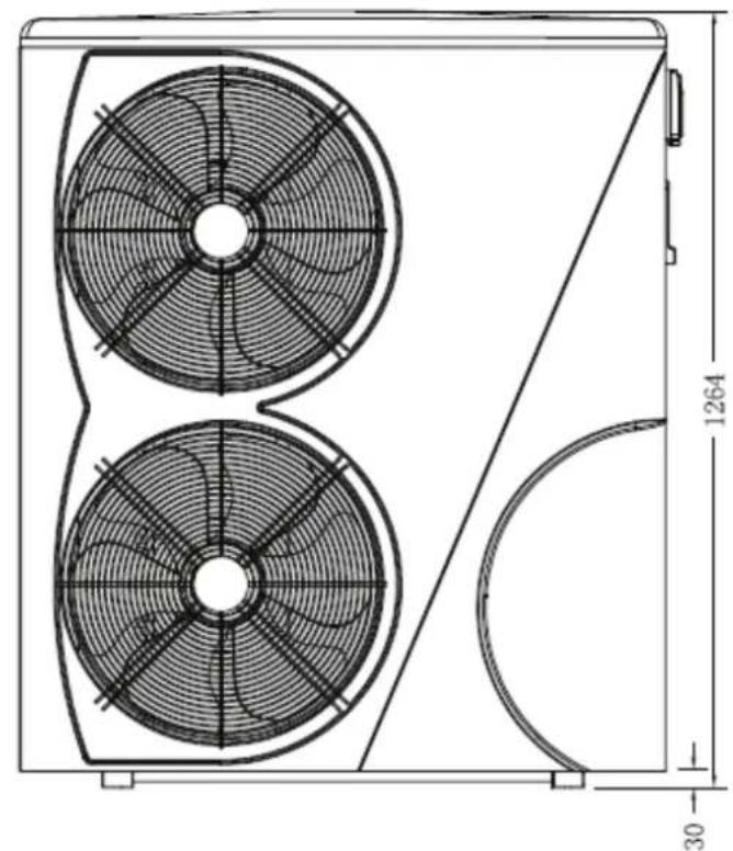
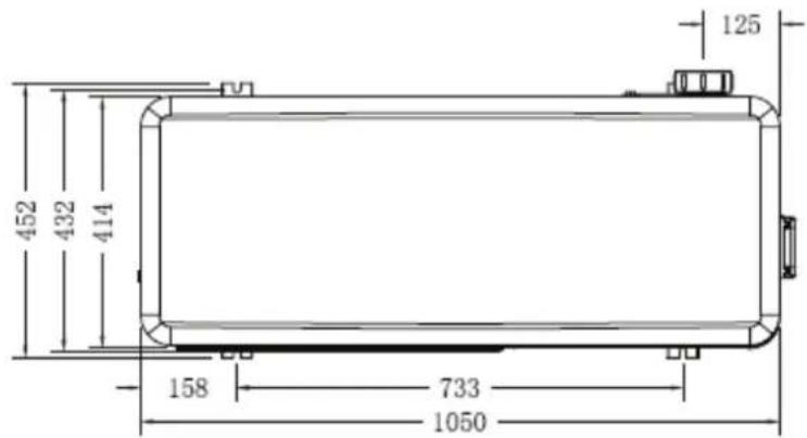
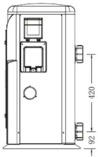
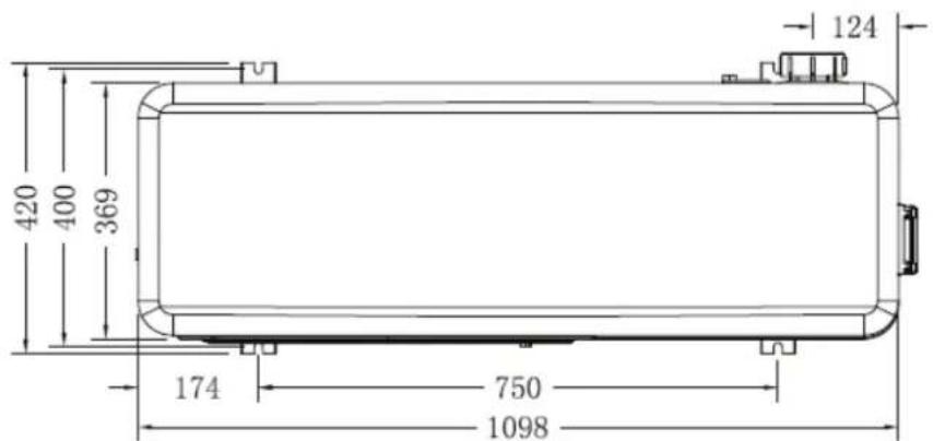
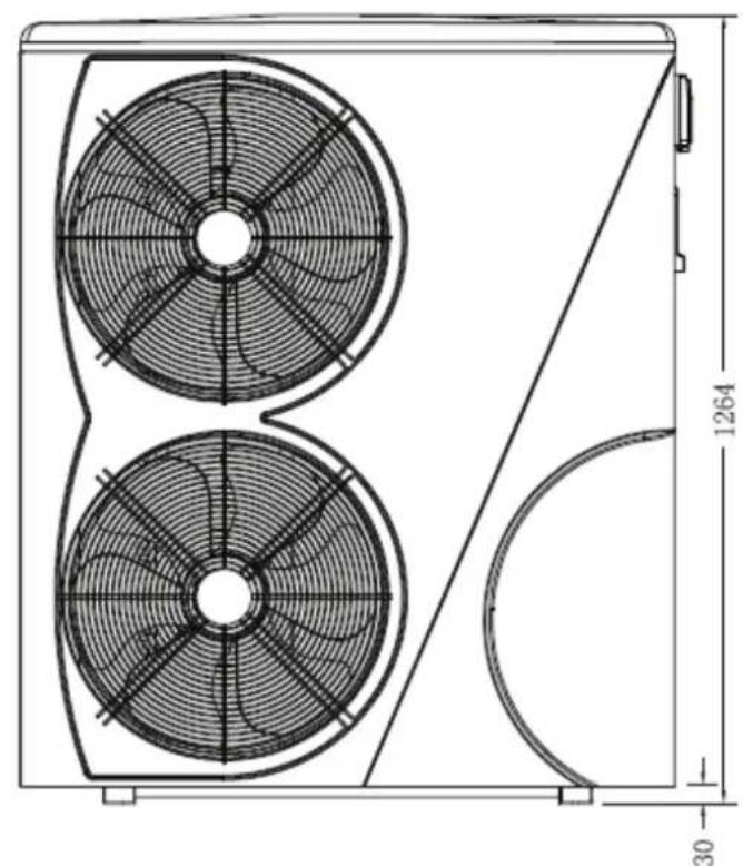
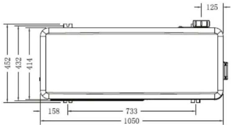
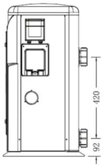
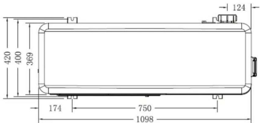
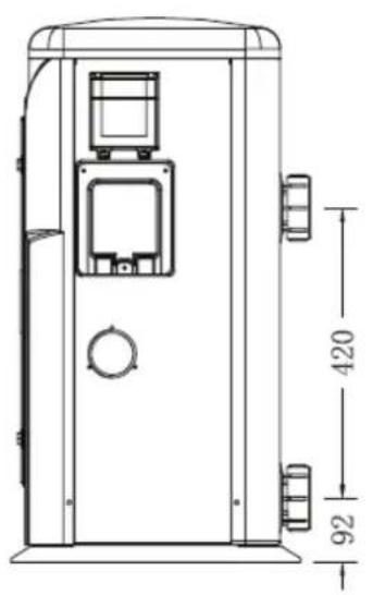
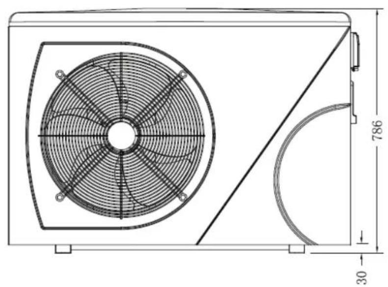
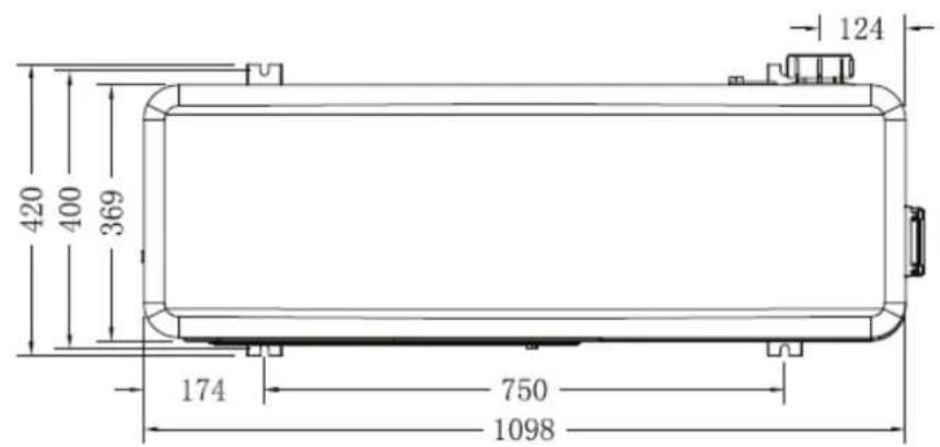
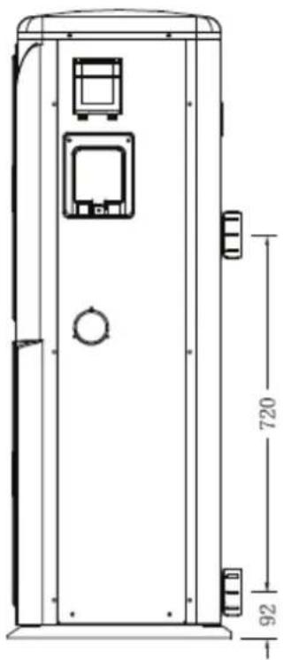
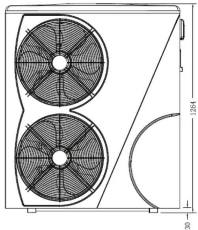
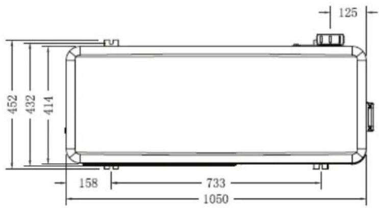
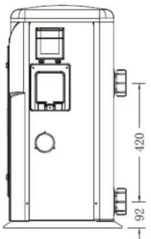
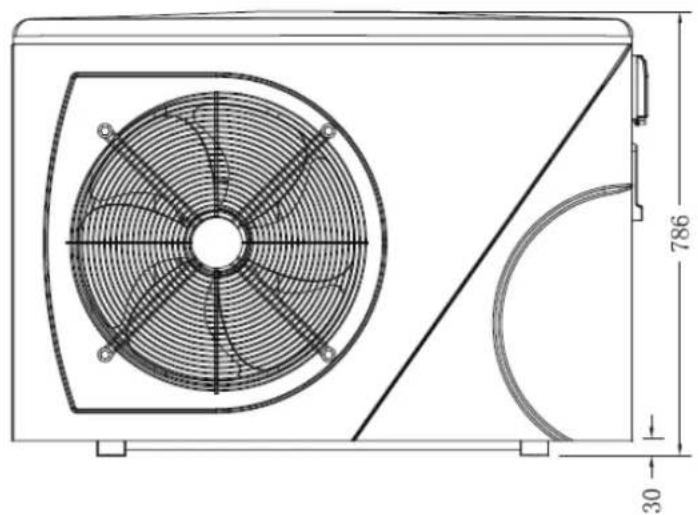
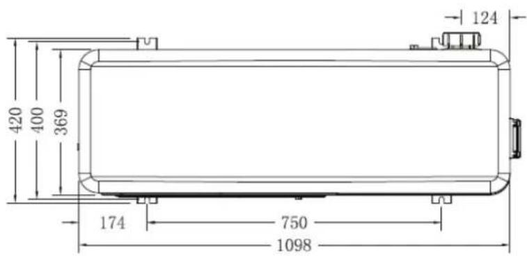
1.2 Dimension
Pro-Elyo Inverter 13


2. Specifications
Technical data PRO-ELYO Inverted heapumps
CE Standard, R410A, Heating and Cooling, invedempressor, compresso defrosting, ABS Cabinet
| Model PRO-ELYO INVERTER 13 | PRO-ELYO INVERTER 21 | PRO-ELYO INVERTER 35 | ||
| CODE 66108 66109 66110 | ||||
| * Performance at Air 27℃, Water 27℃, Humidity 80% | ||||
| Heating (Max./Std./Min.) | kW | 13.5/9.3/6.3 | 21/15.8/10.5 | 33/24.8/16.5 |
| Power consumption (Std.) | kW | 1.23 | 2.08 | 3.26 |
| C.O.P. (Std.) | 7.6 | 7.6 | 7.6 | |
| * Performance at Air 15℃, Water 26℃, Humidity 70% | ||||
| Heating (Max./Std./Min.) | kW | 11.5/7.2/4.5 | 15/11/7.3 | 25/18.7/12.5 |
| Power consumption (Std.) | kW | 1.21 | 2.02 | 3.34 |
| C.O.P. (Std.) | 5.6 | 5.6 | 5.6 | |
| * Performance at Air 5℃ | ||||
| Heating (Max./Std./Min.) kW | 9.5/6.1/3.8 | 10.8/8.0/4.5 | 18.6/14.9/8.5 | |
| Power consumption (Std.) | kW | 1,36 | 1,78 | 3,21 |
| C.O.P. (Std.) | 4,5 | 4,5 | 4,6 | |
| * Performance at Air -5℃ | ||||
| Heating (Max./Std./Min.) kW | 5.3/4.3/2.8 | 7.8/6.1/3.5 | 12.6/9.9/5.2 | |
| Power consumption (Std.) | kW | 1,34 | 1,88 | 3,1 |
| C.O.P. (Std.) | 3,2 | 3,2 | 3,2 | |
| Voltage | 220~240V/50Hz/1PH | 380V/50Hz/3PH | ||
| Std. Current Input | A | 5.4 | 9 | 6.4 |
| Maximum Current | A | 13.9 | 18.2 | 18.3 |
| Fuse | A | 30 | 40 | 40 |
| Advised water flux | M3/h | 4 | 6.2 | 9 |
| Refrigerant | g | 1600 2400 | 3800 | |
| Advised pool volume(with pool cover) | m3 | 38-68 | 75-120 | 120-160 |
| Water Pressure Drop | Kpa | 13 | 16 | 18 |
| Water in-out connection | mm | 50 | ||
| Fan quantity | 1 | 2 | ||
| Fan Speed | 650/450 | |||
| Ventilation type | Horizontal | |||
| Compressor type | DC Inverter Rotary | |||
| Noise level at 1m | dB(A) | 50 | 50 | 52 |
| Noise level at 10m | dB(A) | 46 | 46 | 47 |
| Net dimension | mm | 1098*420*786 | 1050*452*1264 | |
| Net weight Kg | 78 | 91 | 145 | |
| Packing dimension | mm | 1160*455*915 | 1115*500*1395 | |
| Gross weight | Kg | 83 | 101 | 160 |
- Above data are subjects to modification without notice.
3. Adjust the yypasskit
Kit By-Pass
The kit By-Pass is the essential accessory for the installation of your heat pump; it is also a tool for the optimization of the heating of the water. The regulation of the valves allows to optimize the flow of water and with the manometer to make sure the optimize running of the compressor.
ATTENTION:
Please observe the following rules when installing the heat pump:
- Any addition of chemicals must take place in the piping located downstream the heat pump.
- Always place the heat pump on a solid foundation and use the included rubber mounts to avoid vibration and noise.
- Always hold the heat pump upright. If the unit has been held at an angle, wait at least 24 hours before starting the heat pump.
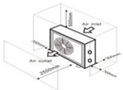
4.1 Heat pump location
The unit will work properly in any desired location as long as the following three items are present:
-
Fresh air
-
Electricity
-
Swimming pool filters
The unit may be installed in virtually any outdoor as long as the specified minimum distances to other objects are maintained (see drawing below). Please consult your installer for installation with an indoor pool. Installation in a windy location does not present any problem at all, unlike the situation with a gas heater (including pilot flame problems).
ATTENTION: Never install the unit in a closed room with a limited air volume in which the air expelled from the unit will be reused, or close to shrubbery that could block the air inlet. locations impair the continuous supply of fresh air, resulting in reduced efficiency and possibly preventing sufficient heat output.
See the drawig below for minimum dimensions.
Such
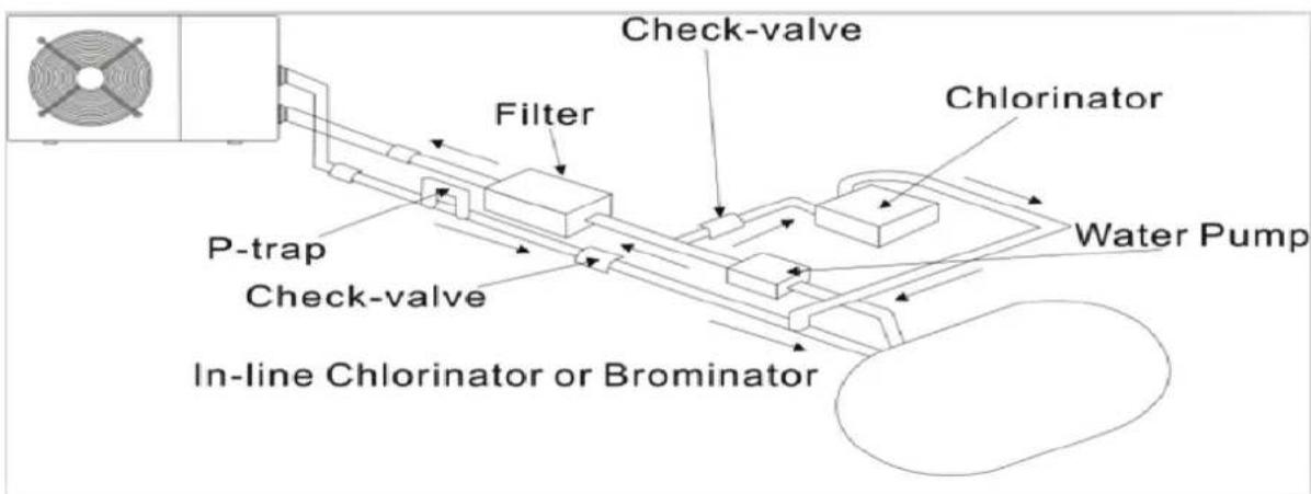
4.2 Check-valve installation

NOTE
Note: If automatic dosing equipment for chlorine and acidity (pH) is used, it is essential to protect the heat pump against excessively high chemical concentrations which may corrode the heat exchanger. For this reason, equipment of this sort must always be fitted in the piping on the downstream side of the heat pump, and it is rSMARTmended to install a check-valve to prevent reverse flow in absence of water circulation.
Damage to the heat pump caused by failure to observe this instruction is not covered by the warranty.
4.3 Typical arrangement
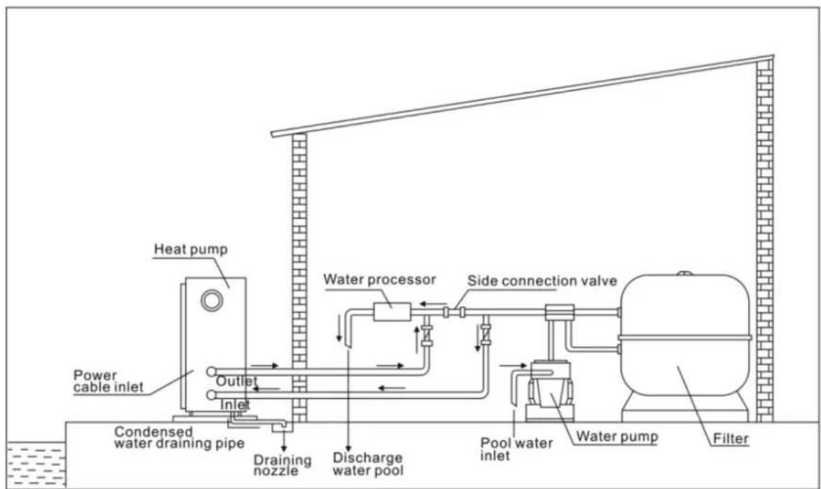
This arrangement is only an illustrative example.
The factory supplies only the heat pump. All other components, including a bypass if necessary, must be provided by the user or the installer.
ATTENTION:
In order to heat the water in the pool (or hot tub), the filter pump must be r to cause the water to circulate through the heat pump. The heat pump will not start up if the water is not circulating.
4.4 Initial operation
After all connections have been made and checked, carry out the following procedure:
- Switch on the filter pump, check for leaks and verify that water is flowing from and to the swimming pool.
- Connect power to the heat pump and press the On/Off button on the LED control panel. The unit will start up after the time delay expires (see below).
- After a few minutes, check whether the air blowing out of the unit is cooler.
- When turn off the filter pump, the unit should also turn off automatically, if not, then adjust the flow switch.
- Allow the heat pump and the filter pump to run 24 hours a day until the above 1 degree than desired water temperature is reached. The heat pump will stop running at this point. After this, it will restart automatically (as long as the filter pump is running) whenever the swimming pool water temperature drops 1 degree below the set temperature.
Depending on the initial temperature of the water in the swimming pool and the air temperature, it may take several days to heat the water to the desired temperature. A good swimming pool cover can dramatically reduce the required length of time.
Water Flow Switch:
It is equipped with a flow switch for protecting the HP unit running with adequate water flow rate. It will turn on when the pool pump runs and shut it off when the pump shuts off.
Time delay - The heat pump has a built-in 3-minute start-up delay to protect the circuitry and avoid excessive contact wear. The unit will restart automatically after this time delay expires. Even a brief power interruption will trigger this time delay and prevent the unit from restarting immediately. Additional power interruptions during this delay period do not affect the 3-minute duration of the delay.
4.5 Condensation
The air drawn into the heat pump is strongly cooled by the operation of the heat pump for heating the pool water, which may cause condensation on the fins of the evaporator.

NOTE
The amount of condensation may be as much as several liters per hour at high relative humidity. This is sometimes mistakenly regarded as a water leak.
4.6 Pressure gauge display (R410A)
Examine the pressure gauge which indicates the refrigerant gas pressure of the unit, the below table shows the normal value of the gas pressure (R410A) when the machine is in power off or running conditions.
| Unit Condition Power | Off | |||
| Ambient (°C) | -5~5 5~15 | 15 | 25 | 25~35 |
| Water temp (°C) | / | / | / | / |
| Pressure gauge (Mpa) | 0.68~0.93 | 0.93~1.25 | 1.25~1.64 | 1.64~2.1 |
| Unit Condition | Running | ||||
| Ambient (℃) | / | / | / | / | / |
| Water temp (℃) | 10~15 | 15~20 | 20~25 | 25~30 | 30~35 |
| Pressure gauge (Mpa) | 1.3~1.8 | 1.5~1.9 | 1.6~2.3 | 1.9~2.8 | 2.1~3.5 |
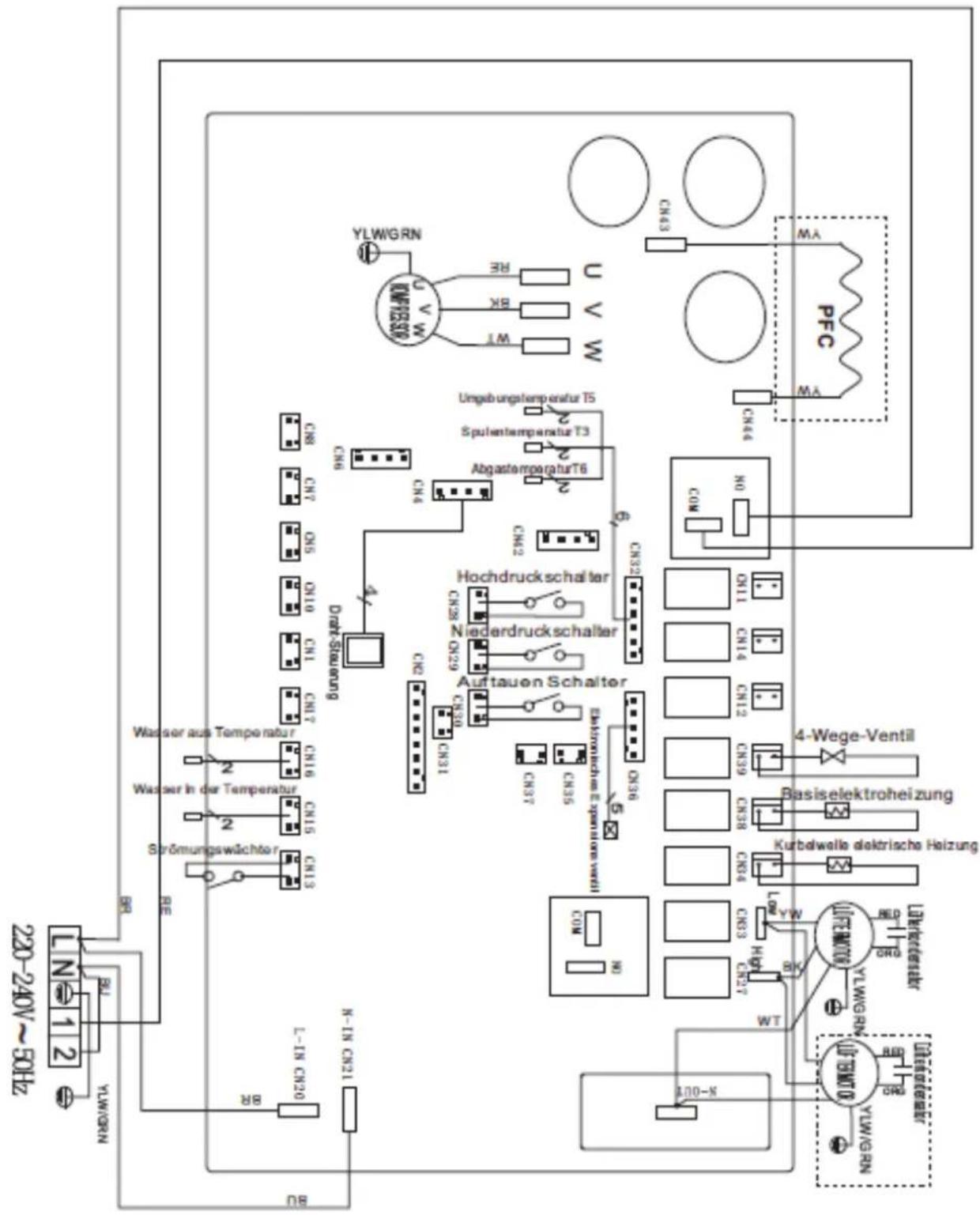
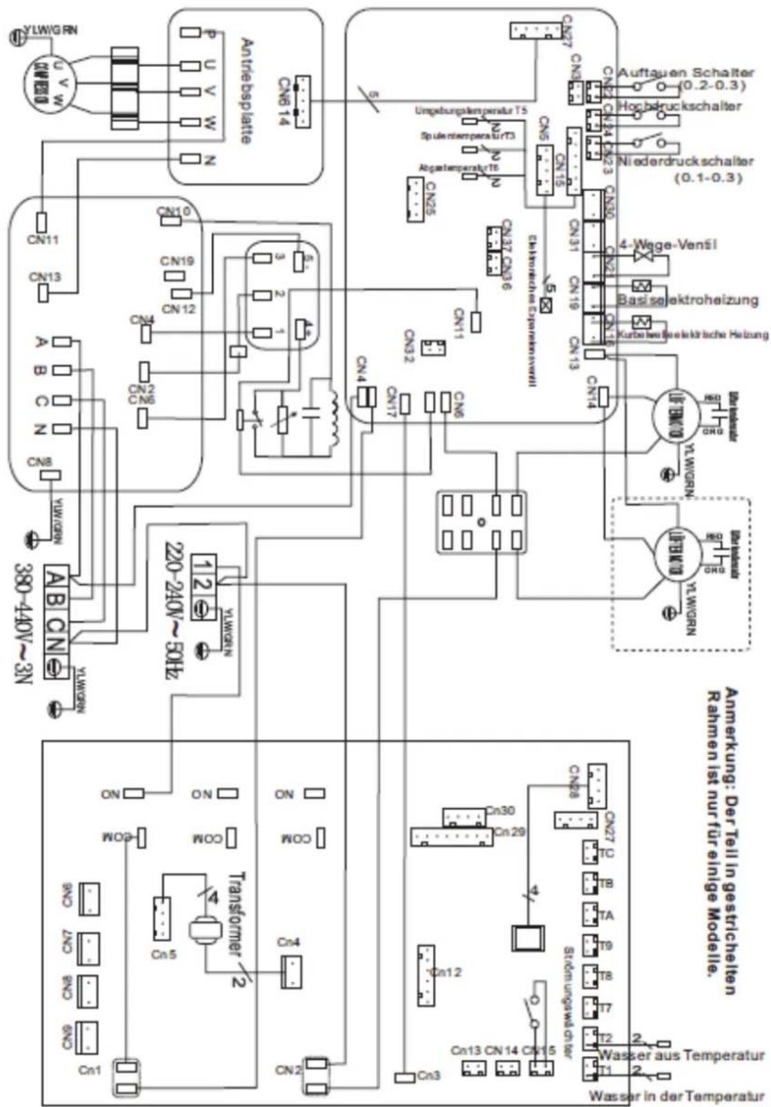
5. EfetfdiaaWVirgg
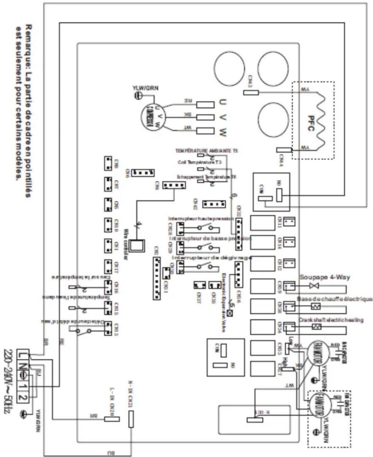
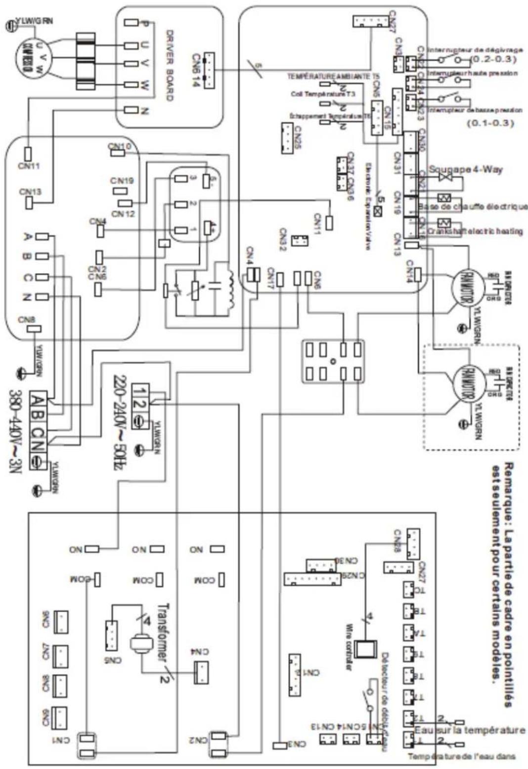
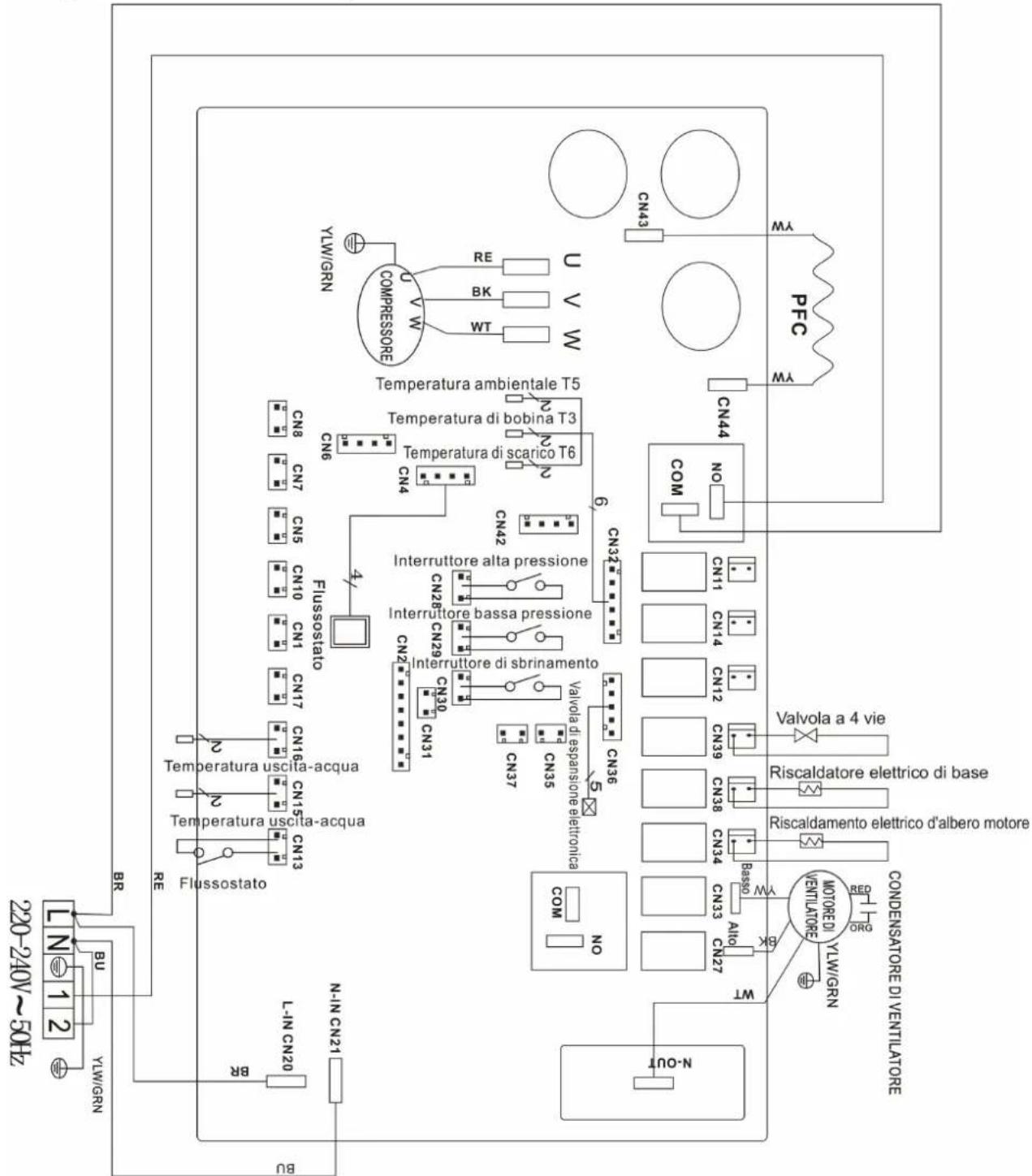
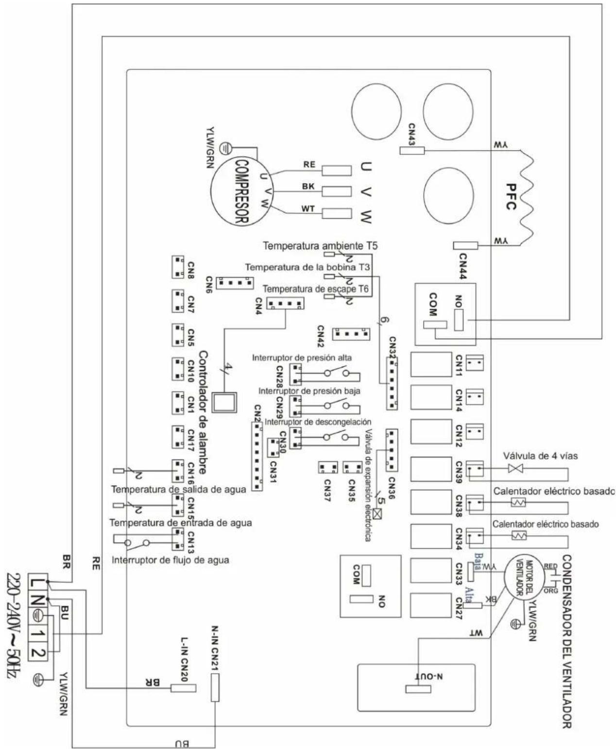
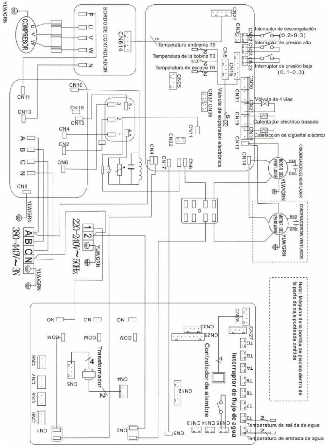
5.1 INVERTER SWIMMING POOL HEAT PUMP WIRING DIAGRAM
PRO-ELYO INVERTER 13 / PRO-ELYO INVERTER 21
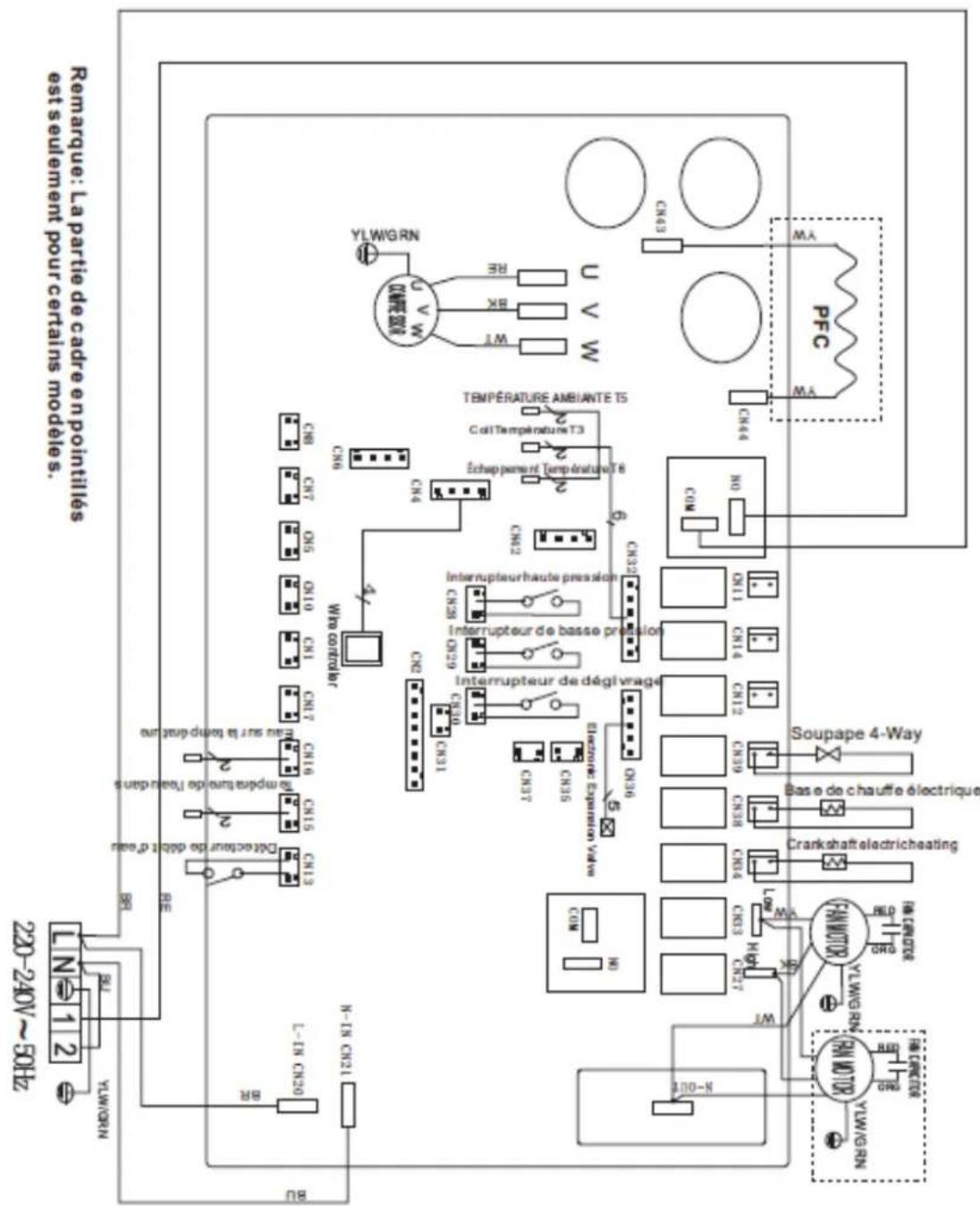
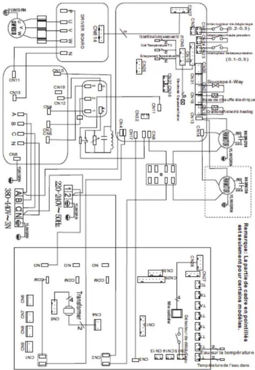
Above electrical wiring diagram only for your reference, please subject machine posted the wiring diagram.
5.2 Electrical protection

NOTE
The swimming pool heat pump must be connected ground wire well, although the unit heat exchanger is electrically isolated from the rest of the unit. Grounding the unit is still required to protect you against short circuits inside the unit. Bonding is also required.
ATTENTION:
Disconnect: A disconnect means (circuit breaker, fused or un-fused switch) should be located within sight of and readily accessible from the unit. This is commonpracticeon commercial and residential heat pumps. It prevents remotely-energizing unattended equipment and permits turning off power at the unit while the unit is baserviced.
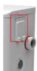
5.3 Installation of the display deportee
Photo(1) Photo(2) Photo(3) Photo(4) Photo(5)
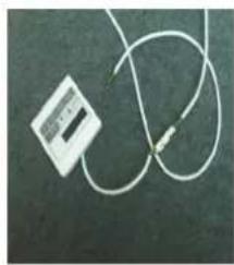

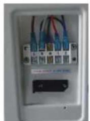
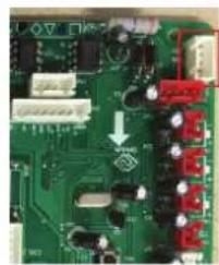
- The side with plug connects with the control panel (photo1)
- The other side of the signal wire. (photo2)
- Open the wiring panel and put the side without plug through the electrical box. (photo3,4)
- Insert the wiring into the designated position (upper right corner) on the PC board. (photo5)
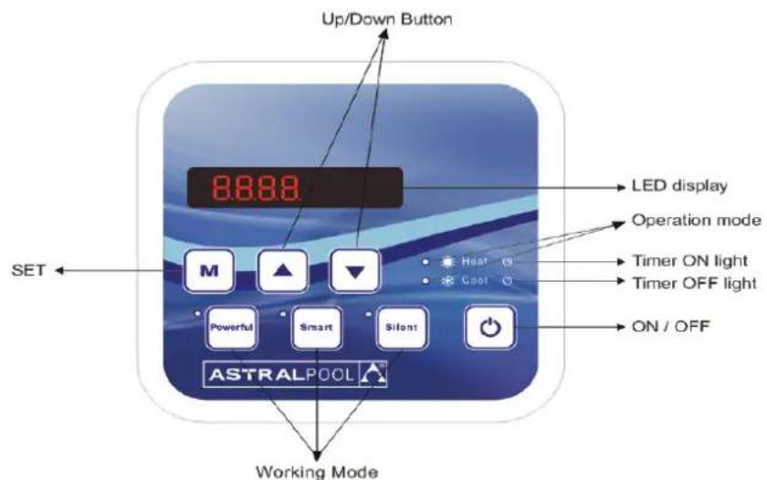
6. Display Controller Operation
6.1. Guide for operation
NOTE
When the swimming pool heat pump is running, the display inform the water temperature. When the Heat
6.2 The keys and their operations
6.2.1 button
Press to start the heat pump unit, the LED display shows the desired water temperature for 5 seconds, then shows the inlet water temperature and the operation mode.
Press to stop the heat pump unit and show "OFF"
Notice : During the parameter checking and setting, press the to quick-exit and save the current setting .
Press again to turn on/off the machine.
6.2.2 M button
Pressfor5s to change the“Heat MODE"or"Cool MODE".
(Notice : this operation is unavailable for the heating only machine)
6.2.3 and button
Watertemperaturesetting:
Pressand to set the water temperature directly.
Parameterchecking:
Press M first, then press to check the "User parameter from d1 to d9.
TIMEchecking:
Press first, then press to check "current time", press again to check the "Automatic start time" press once again to check "Automatic stop time".
TIMEsetting
Press M first, then press the to enter into "Current time" displaying. Then press M once again to enter into "HOUR" setting. The "Hour" flashes, and press the or to set the hour, then press M to save the "Hour". Then the "Minute" flashes, and press the or to set the "Minute" and finally press the M to save the current time setting, or press for quick-exit and saving.
ATTENTION:
If the current time is in the range of time OFF, the machine will be turn OFF automatically after setting the time of automatic start and the time of automatic stop. Whereas the machine will operate normally.
TimerOnsetting:
Press M first, then press the twice to enter into 'Timer on' interface. Then press once again to enter into "HOUR" setting. The "Hour" flashes, and press theor to set the hour, then press
M to save the "Hour". Then the "Minute" flashes, and press the or to set the "Minute" and finally press the M to save the current time setting, or press for quick-exit and saving. Once you set the timer on successfully, the light will display.
Timeroffsetting:
Press first, then press the three timesto enter into "Timer off" interface. Then press once again to enter into "HOUR" setting. The "Hour" flashes, and press them to set the hour, then press to save the "Hour". Then the "Minute" flashes, and press the or to set the "Minute" and finally press the to save the current time setting, or press for quick-exit and saving. Once you set the timer off successfully, the light will display.
CancelTimerON/OFF
When you set Timer ON/OFF data 00:00, it means cancel the Timer ON/OFF function.
ATTENTION: Above operations, you could press to save the setting and quick-exit the program.

NOTE
In order to heat the water in the pool (or hot tub), the filter pump must be running to cause the water to circulate through the heat pump. The heat pump will not start up if the water is not circulating. If the water is not circulating and the Heat Pump is ON the LED controller inform with the error code ON
Noted:
LED wire controller can operate the water pump after connected additional cable to the pump device in the position of "PUMP" terminal accurately.
When HP stop running in 30 seconds, water pump will shut off automatically
6.2.4 System reset function
6.2.5

Symbol of heating, the light will be on when it is in operation.
When defrosting, the light will flash.
6.2.6

Symbol of cooling, the light will be on when it is in operation.
6.2.7

Symbol of automatic stop, the light will be on when it is in operation.
6.2.8

Symbol of automatic start, the light will be on when it is in operation.
6.2.9

Press this button, the light will be on, the heat pump will operate in Powerful only..
6.2.10

While you choose the Smart, the heat pump will just operate in Smart and Powerful.
6.2.11

While you choose the Silent, the heat pump will just operate in Silent and Smart.
The operating logistic of shift between Silent, Smart and Powerful: the default setting in factory is in Smart operating mode
6.3 The operating logic
NOTED :
setT = Setting water temperature
setT-1 = less 1^ than Setting temperature
setT+1= more 1^ than Setting temperature
6.3.1 The heating operation logic
| Working status Working mode Water in temperature Heat pump working level | ||||
| 1 | setT-1< and < setT+1SMARMART | ≤setT-1 POWERFUL | ||
| 2 | ||||
| 3 | ≥setT+1 Standby | |||
| 4 | Start-up of heat pump setT-1< and < setT+1SILENCENT | ≤setT-1 SMART | ||
| 5 | ||||
| 6 | ≥setT+1 Standby | |||
| 7 | POWERFUL | <setT+1 POWERFUL | ||
| 8 | ≥ setT+1 Standby | |||
| 9 | setT-3< and SMART | >setT -1 Standby | ||
| 10 | ≤setT-1 | SMART | ||
| 11 | ≤setT-3 POWERFUL | |||
| 12 | Re-start to heat water in standby status setT-3< and SILENT | >setT -1 Standby | ||
| 13 | ≤setT-1 | SILENT | ||
| 14 | ≤setT-3 SMART | |||
| 15 | POWERFUL | ≤setT-1 POWERFUL | ||
6.3.2 The Cooling operation logic
| Working status Working mode Water in temperature Heat pump working level | ||||
| 1 | Start-up of heat pump | SMART | ≤ setT-1 | Standby |
| 2 | setT-1< and <setT+1 | SMART | ||
| 3 | ≥ setT+1 | POWERFUL | ||
| 4 | SILENT | ≤ setT-1 | Standby | |
| 5 | setT-1< and <setT+1 | QUIET | ||
| 6 | ≥ setT+1 | SMART | ||
| 7 | POWERFUL | >setT-1 | POWERFUL | |
| 8 | ≤ setT-1 | Standby | ||
| 9 | Re-start to cool water in standby status | SMART | ≥ setT+1 and <setT+3 | SMART |
| 10 | ≥ setT+3 | POWERFUL | ||
| 11 | SILENT | ≥ setT+1 and <setT+3 | SMART | |
| 12 | ≥ setT+3 | POWERFUL | ||
| 13 | POWEFUL | ≥ setT+1 | POWERFUL | |
| 14 | ≤ setT | Standby | ||
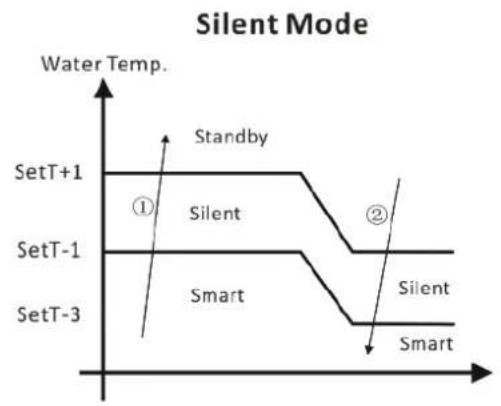
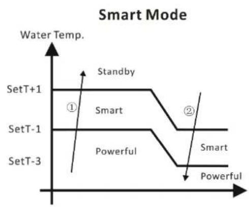
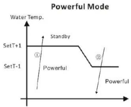
NOTE: ① Water temperature rise ② Water temperature drop
6.4 About the ambient temperature for the working frequency
When you choose the "POWERFUL working mode, if the ambient temperature ≥ 30^ and < 35^ the working frequency will stay in limited level. If the ambient temperature ≥ 50^, the heat pump will stop operation and display the error code PP09 for compressor protection.
6.5 About the limitation of water in temperature
Water in temperature ≤ 7^ , the heat pump will stop operation.
Note : If the water filtration system is stop before the heat pump, the unit will down (security condition) and the code EE3 or ON advertise on the controller. It is important to program the heat pump link the time program of the water filtration system. For restart the heat pump, turn off and turn on the electrical power supply to restart the unit.
7. Parameters
7.1 How to know the current status
Press M first, then press to check the user parameter from d1 to d9 as below:


| Parameter Name | Range Remarks | ||
| d1 Inlet water temperature | -9-99 °C | Real testing value | |
| d2 Outlet water temperature -9-99 °C Real testing value | |||
| d3 Ambient temperature | -F(-30°C)-70°C | Real testing value | |
| d4 Gas return temperature | -F(-30°C)-70°C | Real testing value | |
| d5 | Coil temperature | -F(-30°C)-70°C | Real testing value |
| d6 Gas exhaust temperature | 0-C5°C(125°C) | Real testing value | |
| d7 Steps of electronic expansion valve 0-99 N*5 | |||
| d8 Compressor operating frequency | 0-99Hz | Real testing value value | |
| Powerful: 65,70,75Hz | |||
| Smart: 50,55,60Hz | |||
| Silent: 30,35,40,45Hz | |||
| d9 Compressor current 0-30A | Real testing value | ||
Recover to Factory default setting
Long press and at the same time for 10 second to recover to factory default setting, it will display '0000' for 5 seconds is still required to protect you against short circuits inside the unit. Bonding is also required.
(1) When HP stop running in 30 seconds, water pump will shut off automatically
(2) LED wire controller can operate the water pump after connected additional cable to the pump device in the position of "PUMP" terminal accurately.
(3) It is necessary to put an extra 3-phase transfer device for 3 phase water pump.
8. Troubleshooting
8.1 Error code display on LED wire controller
| Malfunction Error code | Reason | Solution | |
| Inlet water temperature sensor failure | PP01 The sensor in open or short circuit Check or change the sensor | ||
| Outlet water temperature sensor failure | PP02 The sensor in open or short circuit Check or change the sensor | ||
| Heating condenser sensor failure | PP03 The sensor in open or short circuit Check or change the sensor | ||
| Gas return sensor failure PP04 The sensor in open or short circuit Check or change the sensor | |||
| Ambient temperature sensor failure | PP05 The sensor in open or short circuit Check or change the sensor | ||
| Condenser gas exit sensor failure | PP06 The sensor in open or short circuit Check or change the sensor | ||
| Antifreeze protection in Winter PP07 Ambient temperature or water inlet temperature is too low | |||
| Low ambient temperature protection | PP08 Ambient temperature or water inlet temperature is too low | ||
| Ambient temperature is too in heating mode | PP09 Ambient temperature is too high | Stop the heat pump and wait the ambient temperature at less than Air 50℃ (less 5℃ in allowance)The error code will disappear automatically | |
| Cooling condenser temperature too high protection | PP10 Cooling condenser temperature is too high | Stop the heat pump and wait the cooling condenser temperature drop down | |
| High pressure failure | EE01 1. Refrigerant is too much2. Air flow is not enough | 1.Discharge redundant refrigerant from HP gas system2.Clean the air exchanger | |
| Low pressure failure | EE02 1. Refrigerant is not enough2.Water flow is not enough3. Filter jammed or capillary jammed | 1.Check if there is any gas leakage ,re-fill the refrigerant2.Clean the air exchanger3.Replace the filter or capillary | |
| Water flow failure | EE03 or "ON" Low water flow, wrong flow direction, or flow switch failure. | Check if the water flow is enough and flow in right direction, or else the flow switch could be failed. | |
| Malfunction Error | code Reason Solution | ||
| Gas exhaust temperature sensor failure | EE05 Defrosting | is not good Lack of gas The throttling device jammed Low water flow | Defrosting by hand Plus the gas iChange the throttling device Check the water pump |
| Controller failure EE06 Wire | connection is not good | Controller failure | Check or change the signal wire Restart the power supply or change the controller |
| Converter failure EE07 Converter board failure Restart the power supply or change the converter board | |||
| Communication failure between controller and converter board | EE08 Wire connection is not good Controller failure | Check or change the wire connection Restart the power supply or change the controller | |
| Communication failure between converter and outdoor board | EE09 Wire connection between communication wire and outdoor board is wrong Outdoor board failure | Rewiring Restart the power supply or change the outdoor board | |
| module board failure between outdoor board and module board | EE10 Communication wire is broken Outdoor board or module board failure | Restart the power supply or change the broken board | |
| Module board failure | EE11 | The data is wrong or the module board is broken | Restart the power supply or change the broken board |
| Direct main current's voltage too high or too low protection | EE12 | The pressure is too high or too low The inner communication contactor is broken | Check the power supply Change the contactor |
| Over current protection | EE13 | Electric supply pressure is too low, the heat pump is overload | Check the power supply Check the water temperature whether it is too high |
| Symbol of Defrosting, the heating light is on | Defrosting | ||
8.2 Other Malfunctions and Solutions (No display on LED wire controller)
| Malfunctions Observing Reasons Solution | |||
| Heat pump is not running | LED wire controller no display. | No power supply | Check cable and circuit breaker if it is connected |
| LED wire controller. Displays the actual time. | Heat pump under standby status | Startup heat pump to run. | |
| LED wire controller displays the actual water temperature. | 1. Water temperature is reaching to setting value, HP under constant temperature status. 2. Heat pump just starts to run. 3. Under defrosting. | 1. Verify water temperature setting. 2. Startup heat pump after a few minutes. 3. LED wire controller should display "Defrosting". | |
| Water temperature is cooling when HP runs under heating mode | LED wire controller displays actual water temperature and no error code displays. | 1. Choose the wrong mode. 2. Figures show defects. 3. Controller defect. | 1. Adjust the mode to proper running 2. Replace the defect LED wire controller, and then check the status after changing the running mode, verifying the water inlet and outlet temperature. 3. Replace or repair the heat pump unit |
| Short running | LED displays actual water temperature, no error code displays. | 1. Fan NO running. 2. Air ventilation is not enough. 3. Refrigerant is not enough. | 1. Check the cable connections between the motor and fan, if necessary, it should be replaced. 2. Check the location of heat pump unit, and eliminate all obstacles to make good air ventilation. 3. Replace or repair the heat pump unit. |
| water stains | Water stains on heat pump unit. | 1. Concreting. 2. Water leakage. | 1. No action. 2. Check the titanium heat exchanger carefully if it is any defect. |
| Toomuchiceon evaporator | Too much ice on evaporator. | 1. Check the location of heat pump unit, and eliminate all obstacles to make good air ventilation. 2. Replace or repair the heat pump unit. | |
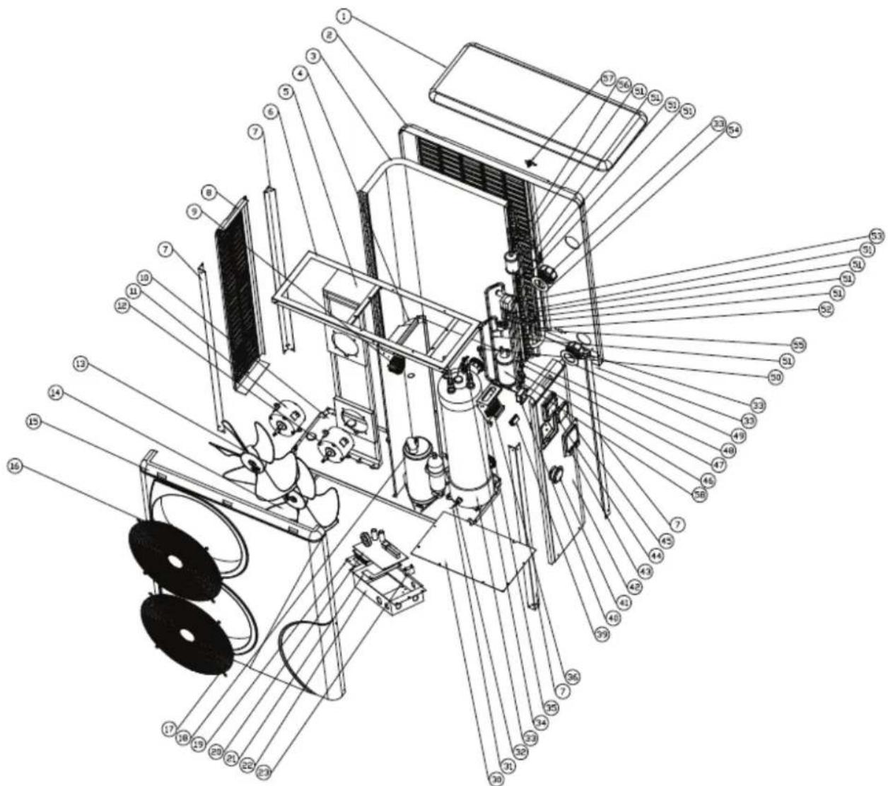
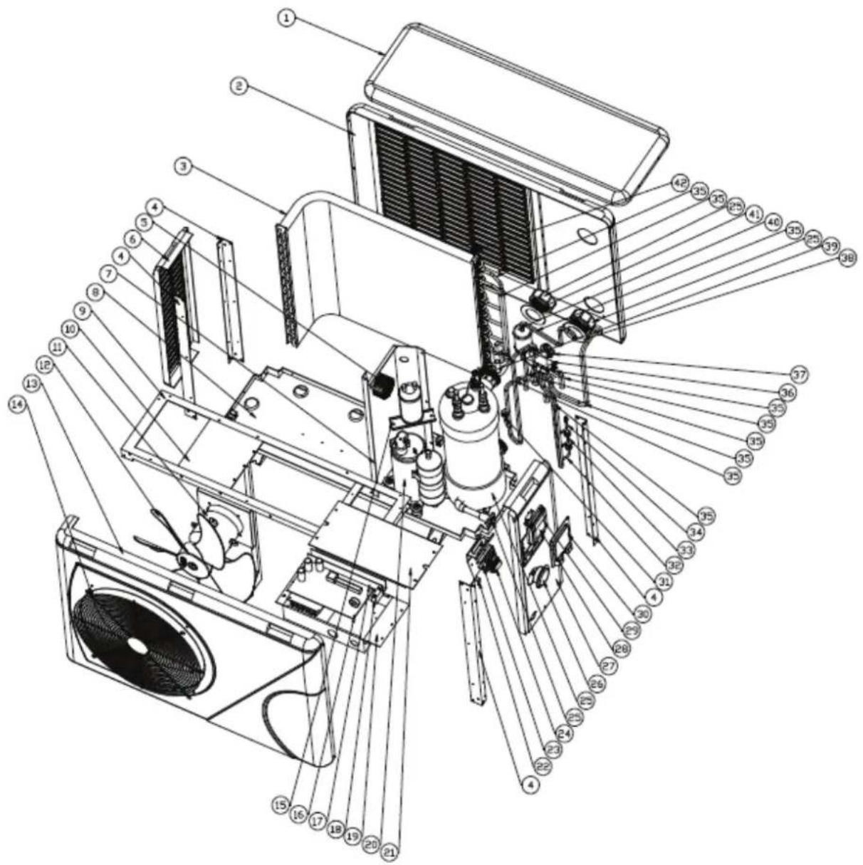
99 Exploded Explored Diagmantine Mantaince
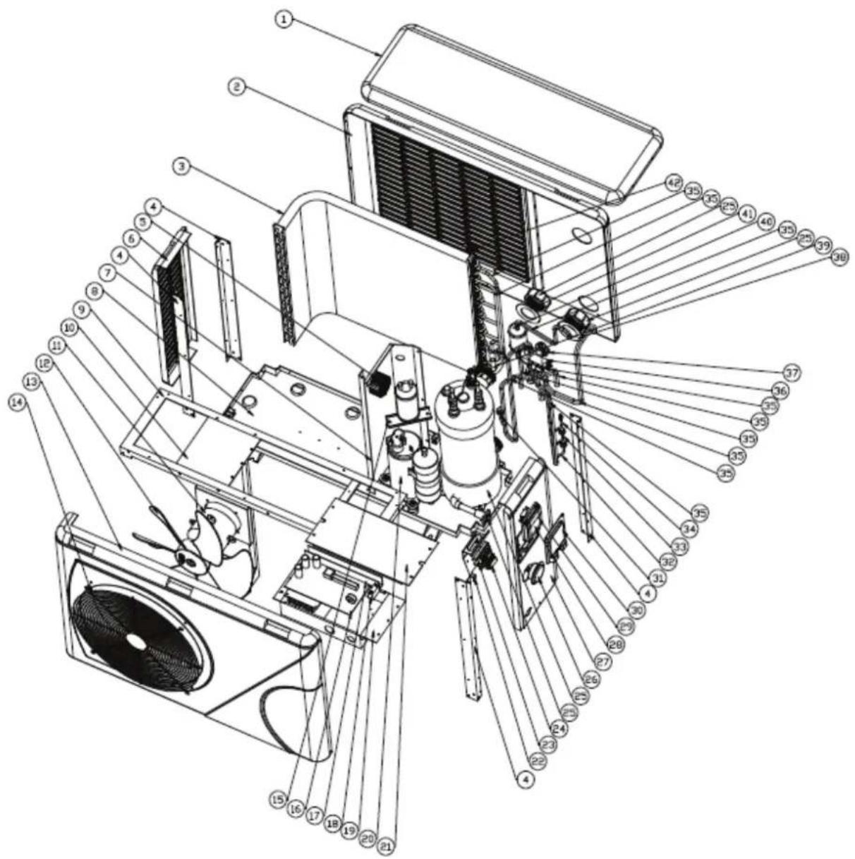
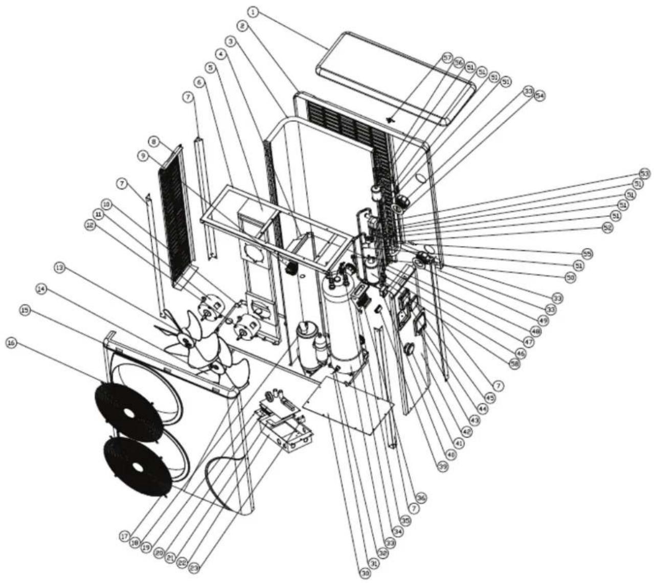
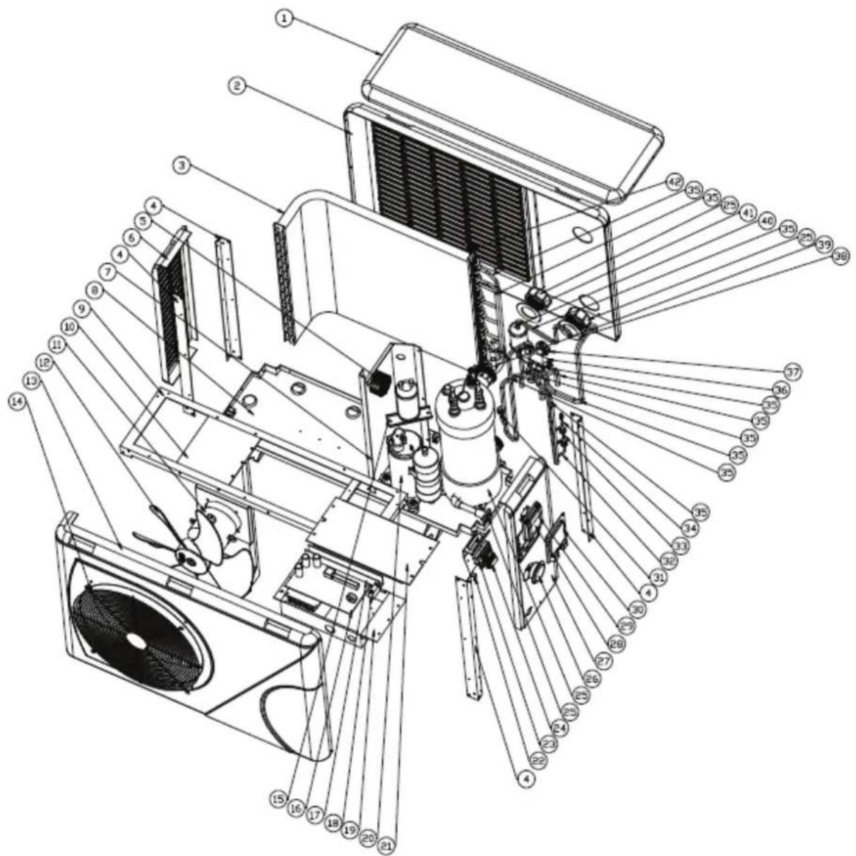
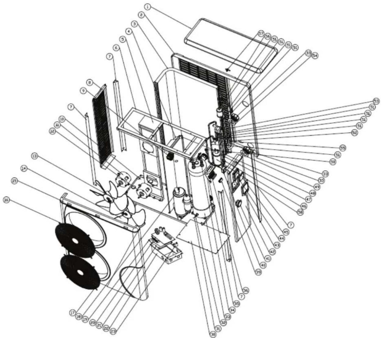
9. 1 Exploded Diagram
Pro-Elyo Inverter 13

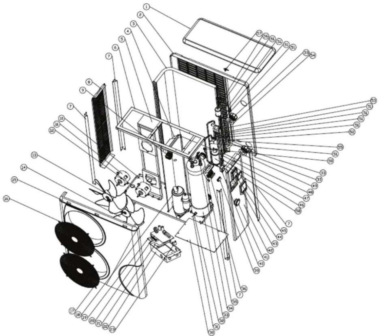

9.2 Parts list
9.2.1 Pro-Elyo Inverter 13
| NO | Part Name | ERP NO | Part Name | ERP | |
| 1 | Top cover | 133070019 | 23 | Terminal block | 105000004 |
| 2 | Back panel | 133070031 | 24 | Clip | 136010004 |
| 3 | Evaporator | 103000104 | 25 | Titanium heat exchanger | 102040410 |
| 4 | Pillar | 108160016 | 25 | Heat exchanger bottom plug | 102040410 |
| 5 | PFC inductor | 117220001 | 25 | Water connection cover | 102040410 |
| 6 | Left side panel | 133070022 | 25 | Water connection cover | 102040410 |
| 7 | Isolated panel | 108160028 | 26 | Pressure gauge | 106000001 |
| 8 | Base tray | 108160044 | 27 | Right panel | 133070012 |
| 9 | Top frame bracket | 108160027 | 28 | Waterproof controller box | 133020003 |
| 10 | Fan motor bracket(H series) | 108160029 | 29 | Controller | 117020097 |
| 11 | Fan motor | 112000009 | 30 | Wiring box | 108010018 |
| 12 | Fan blade | 132000013 | 31 | High pressure switch | 116000008 |
| 13 | Front panel | 133070006 | 32 | Low pressure switch | 116000016 |
| 14 | Front grill | 108160012 | 33 | Low pressure switch | 116000020 |
| 15 | Liquid storage pot | 105000004 | 34 | Suction valve | 120000026 |
| 16 | Inverter integration mainboard | 117100006 | 35 | Piping 114000044 | |
| 17 | slot | 136020003 | 36 | 4-way valve | 121000009 |
| 18 | Fan motor capacitor | 111000005 | 37 | EEV | 119000021 |
| 19 | Controller box | 108160030 | 38 | Water inlet rubber ring (blue) | 133020011 |
| 20 | Compressor | 101000115 | 39 | Water flow switch | 116000001 |
| 21 | Electric box cover | 108160031 | 40 | Filter | 120000066 |
| 22 | Terminal block box | 108160024 | 41 | Water outlet rubber ring (red) | 133020012 |
| 42 | Ambient temperature sensor clip | 113715001 | |||
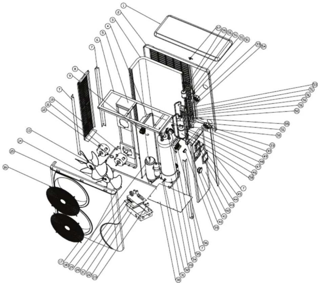
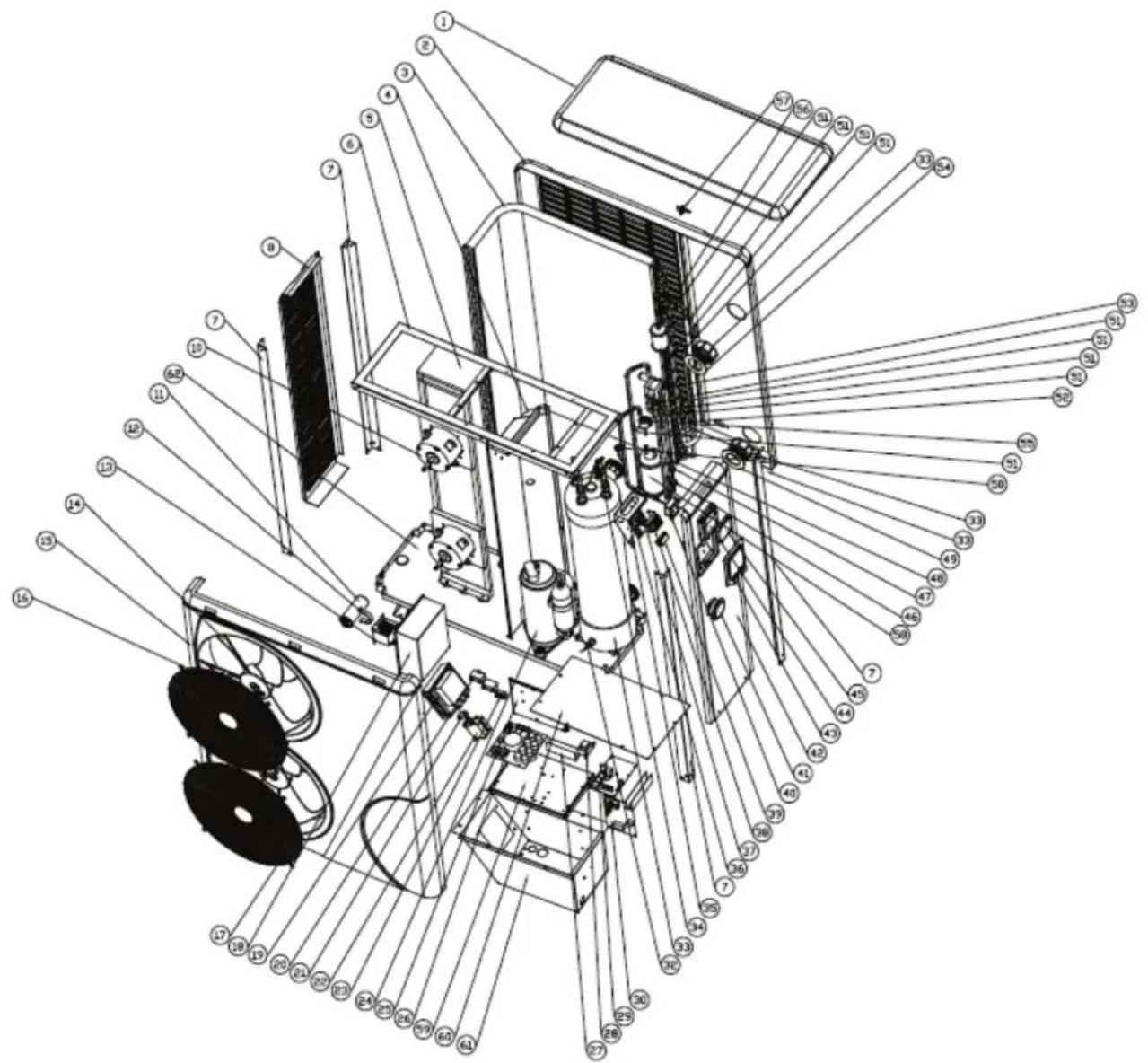
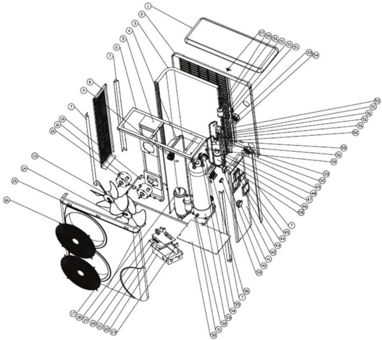
9.2.2 Pro-Elyo Inverter 21
| NO | Part Name ERP NO Part Name | ERP | |||
| 1 | Top cover 133100001 33 Titanium | exchanger | 10 | 2040397 | |
| 2 | Back panel 133070032 33 Heat | exchanger | bottom | plug 102040397 | |
| 3 | Evaporator | 133000036 | 33 | Water connection cover | 102040397 |
| 4 | Isolated panel | 108120026 | 33 | Water connection cover | 102040397 |
| 5 | Fan motor bracket | 108120010 | 34 | Water flow switch | 116000001 |
| 6 | Top frame bracket | 108120005 | 35 | Terminal blocks panel | 108120020 |
| 7 | Pillar | 108120007 | 36 | Five-position blocks | 115000004 |
| 8 | Left side panel | 133100012 | 39 | Clip | 136010004 |
| 9 | PFC Inductor | 117220002 | 40 | Wiring box | 108010018 |
| 10 | Base tray 108120025 | 41 High | pressure gauge | 106000001 | |
| 11 | Fan motor | 112000009 | 42 | Right side panel | 133070033 |
| 12 | Fan motor | 112000009 | 43 | Terminal blocks plastic cover | 133100011 |
| 13 | Fan blade | 132000013 | 44 | Waterproof controller box | 133020003 |
| 14 | Fan blade 132000013 | 45 | Controller | 117020097 | |
| 15 | Front panel | 133100006 | 46 | Low pressure switch | 116000019 |
| 16 | Front grill | 108160012 | 47 | Low pressure switch | 116000016 |
| 17 | Front grill | 108160012 | 48 | Suction valve | 120000023 |
| 18 | Compressor | 101000130 | 49 | Water inlet rubber ring (blue) | 133020011 |
| 19 | Main board fixed panel | 108050029 | 50 | High pressure switch | 116000008 |
| 20 | Frequency conversion integrated motherboard | 117100008 | 51 | Piping | 113010013 |
| 21 | Main board fixed panel | 108050029 | 52 | Temperature sensor casing | 113190001 |
| 22 | Controller box | 108120027 | 53 | 4 way valve | 121000009 |
| 23 | Fan motor capacitor | 1110000054 | 54 | Water outlet rubber ring (red) | 133020012 |
| 30 | Controller box cover | 108120028 | 55 | EEV | 119000021 |
| 31 | temperature sensor | 117110014 | 56 | Filter | 120000066 |
| 32 | Heat exchanger temperature sensor clamp | 108010025 | 57 | Ambient temperater sensor clip | 133020010 |
| 58 | Liquid storage pot | 1050000 | |||
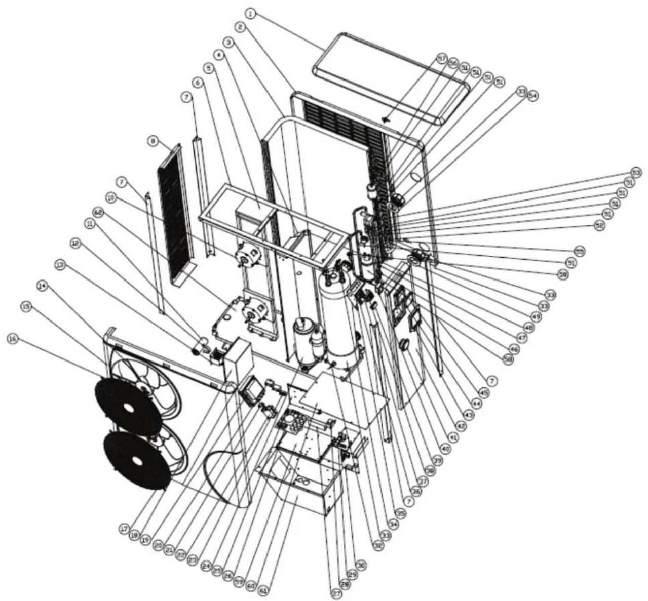
9.2.3 Pro-Elyo Inverter 35
| NO | Part Name ERP NO Part Name ERP | ||||
| 1 | T o | 133100001 | 33 | Heat exchanged bottom plug | 102040411 |
| 2 | Back panel | 133070032 | 33 | Water connection cover | 102040411 |
| 3 | E v | 103080109 | 33 | Water connection cover | 102040411 |
| 4 | I s | 108120009 | 34 | Water flow switch e | 116000001 |
| 5 | Fan motor bracket | 108120010 | 35 | Terminal blocks panel | 108120020 |
| 6 | Top frame bracket | 108120006 | 36 | Three-position blocks | 115000025 |
| 7 | Pillar | 108120007 | 37 | Block panel bracket | 108010023 |
| 8 | Left side panel | 133100012 | 38 | Water pump blocks | 115000027 |
| 10 | Fan motor | 112000009 | 39 | Clip | 136010004 |
| 11 | Thin-film capacitor | 111000028 | 40 | Wiring box | 108010018 |
| 12 | Capacitor clip | 108010007 | 41 | High pressure gauge | 106000001 |
| 13 | Electric reactor | 117230001 | 42 | Right side panel | 133070033 |
| 14 | Fan blade | 132000013 | 43 | Terminal blocks plastic cover | 133100011 |
| 15 | Front panel | 133100006 | 44 | Waterproof controller box | 133020003 |
| 16 | Front grill | 108160012 | 45 | Controller | 117020097 |
| 17 | Front grill | 108160012 | 46 | Low pressure switch | 116000020 |
| 18 | Controller box | 108070028 | 47 | Low pressure switch | 116000016 |
| 19 | IPM module | 117080004 | 48 | Suction valve | 120000023 |
| 20 | Fan motor capacitor | 111000005 | 49 | Water inlet rubber ring (blue) | 020011 |
| 21 | Thermistor | 117150001 | 50 | High pressure switch | 116000008 |
| 22 | AC contactor | 104000003 | 51 | Piping | 113010013 |
| 23 | Termical blocks | 115000009 | 52 | Temperatur sensor casing | 113190001 |
| 24 | Compressor | 101000114 | 53 | 4 way valve | 121000009 |
| 25 | Scaleboard | 108120015 | 54 | Water outlet rubber ring | 020012 |
| 26 | Outdoor power board | 117190004 | 55 | EEV | 119000022 |
| 27 | slot | 136020003 | 56 | Filter | 120000066 |
| 28 | linear transformer | 117030005 | 57 | Ambient temperater sensor | 3020010 |
| 29 | Indoor transfer board | 117180021 | 58 | Liquid storage pot | 105000008 |
| 30 | Outdoor control mould | 117200003 | 59 | Scaleboard | 108120016 |
| 31 | Temperature sensor | 117110014 | 60 | Controller box cover | 108120018 |
| 32 | Heat exchanger temperature sensor clamp | 108010025 | 61 | Controller box | 108120013 |
| 33 | Titanium exchanger | 102040411 | 62 | Base | 108120003 |
9.3 Maintenance
(1) You should check the water supply system regularly to avoid the air entering the system and occurrence of low water flow, because it would reduce the performance and reliability of HP unit.
(2) Clean your pools and filtration system regularly to avoid the damage of the unit as a result of the dirty of clogged filter.
(3) You should discharge the water from bottom of water pump if HP unit will stop running for a long time (especially during the winter season).
(4) In another way, you should check the unit is water fully before the unit starts to run again.
(5) After the unit is conditioned for the winter season, he is preconize to cover the heat pump with special winter heat pump.
(6) When the unit is running, there is all the time a little water discharge under the unit.
10. Warranty
1.WARRANTYCOVERAGE
1.1 In accordance with these provisions, the salesman guarantees that the product corresponding to this warranty ("the product") does not present an on-conformance attemomentofitsdelivery.
1.2 The warranty period of the product is of two (2) years and it will take effect as of the time of delivery to the buyer.
1.3 If a Product non-conformance occurs and the buyer notifies it to the salesman during the Warranty Period, the salesman should repair or replace the Product at his own cost in the appropriate place, unless it is impossible or disproportionate.
1.4 When the Product cannot be repaired nor be replaced, the buyer shall be able to ask for a proportional price reduction or, if the non-conformance issufficiently important, the discharge of the sales contract.
1.5 The replaced or repaired parts by virtue of this warranty will not extend the warranty term of the original Product, although they will have its own warranty.
1.6 For the effectiveness of this warranty, the buyer will have to credit the acquisition date and delivery date of the Product.
1.7 When the delivery of the Product to the buyer had been more than six months before and the buyer alleges non-conformance withtheProduct, the buyer will havetoprovetheoriginandexistenceoftheallegedfault.
1.8 The present Warranty Certificate does not limit or prejudges the rights the consumers are entitled by virtue of local prevailing and applicable regulations.
2.CONDITIONS TOWARRANTY
2.1 This warranty covers the products referred to in this manual.
2.2This Warranty Certificate will besolelyapplicable inthe countries of the European Union.
2.3 For the effectiveness of this warranty, the buyer will have to strictly follow the manufacturer instructions included in the documentation enclosed with the Product, whenever this warranty is applicable according to the Product range and model.
2.4 When a calendar for the substitution, maintenance or cleaning of certain parts or components of the Product is specified, the Warrantywillonlybevalidwhenthecalendarhasbeenobserved.
3.LIMITATIONS
3.1 This warranty will be solely applicable to those sales to consumers, being understood "consumers" as those people who acquire the Product with purpose that does not fall within the scope of their professional activity.
3.2 No warranty is granted referred to the wear and tear caused by the use of the Product. In relation to the parts, components and/or consumable materials such as batteries, light bulbs etc, it will refer to the provisions of the documentation enclosed with the Product, when applicable.
3.3 The warranty does not cover those cases where the Product: (I) has been incorrectly treated; (II) has been repaired, maintained or manipulated by a nonauthorized person, or (III) has been repaired or maintained with nonoriginal pieces.
When the non-conformance of the Product is a consequence of an incorrect installation or start-up, this warranty will only cover those installations or start-ups included in the contract of sale of the Product and carried out by the salesman or under his/her responsibility.
Unit
Model
Reference N.
INSTALLER
Name
Town
Address
Telephone
USER
Name
Town
Address
Telephone
Start-up date
(To be filled by the installer)
INSTALLER'S STAMP:
This warranty card should be filled and sent for all COMPISA machines in order to be fully applicable.
Declaressunder their own responsibility that all the Fnat Lympnverter
Manufactured since 31/03/2012, independent of the serial number, are in compliance with:
Machine safety directive 2006/42/EC.
Electromagnetic compatibility directive 2004/108/EC and its modifications.
Low-voltage equipment directive 2006/95/EC.
Directive 2000/14/CE concerning noise produced by equipment for outdoors use, as amended by Directive 2005/88/EC.
Restrictions in the use of certain risky substances in the electrical and electronic instruments 2002/95/EC (RoHS).
Relative to the electrical and electronic waste products 2002/96/EC (RAEE). Relative to the electrical and electronic
instruments and the management of their waste products Spanish R.D. 208/2005.
The registration, the evaluation, the authorization and the restriction of the chemical substances EC N° 1907/2006 (REACH).
Pro-Elyo Inverter 13

Pro-Elyo Inverter 13 / Pro-Elyo Inverter 21

NOTE
Pro-Elyo Inverter 13

9.2.2 Pro-Elyo Inverter 21
Pro-Elyo Inverter 13


2. Especificação
Dados技术和 de bombas deparalopiscinas PRO-ELYO INVERTER
Pro-Elyo Inverter 13

9.2 lista de peças
9.2.1 Pro-Elyo Inverter 13
| NO | Nome da peça | ERP NO | Nome da peça | ERP | |
| 1 | Tampa superior | 133070019 | 23 | Bloco terminal | 105000004 |
| 2 | Painel traseiro | 133070031 | 24 | Grampo | 136010004 |
| 3 | Evaporador | 103000104 | 25 | Permutador de calor de titânio | 102040410 |
| 4 | Pilar | 108160016 | 25 | Permutador de calor de titânio de encaixe inferior | 102040410 |
| 5 | Inductor PFC | 117220001 | 25 | Cobertura de ligação de água | 102040410 |
| 6 | Painel do lado esquerdo | 133070022 | 25 | Cobertura de ligação de agua | 102040410 |
| 7 | Painel isolado | 108160028 | 26 | Medidor de pressão | 106000001 |
| 8 | Bandeja de base | 108160044 | 27 | Painel direito | 133070012 |
| 9 | Suporte da moldura Top | 108160027 | 28 | C ontrolador dacaix a p rova d'água | 133020003 |
| 10 | Suporte do motor do ventilador | 108160029 | 29 | Controlador | 117020097 |
| 11 | Motor de ventilador | 112000009 | 30 | Caix a defiação | 108010018 |
| 12 | Pá do ventilador | 132000013 | 31 | Interruptor de alta pressão | 116000008 |
| 13 | Painel frontal | 133070006 | 32 | Interruptor de baixa pressão | 116000016 |
| 14 | Grade dianteira | 108160012 | 33 | Interruptor de baixa pressão | 116000020 |
| 15 | Pote de armazenamento de liquidos | 105000004 | 34 | Válvula de sução | 120000026 |
| 16 | Inverter integration mainboard | 117100006 | 35 | Piping 114000044 | |
| 17 | Ranhura | 136020003 | 36 | Válvula de 4 vias | 121000009 |
| 18 | Fan capacitor do motor | 111000005 | 37 | EEV | 119000021 |
| 19 | Caixa de controlador | 108160030 | 38 | Água anel de borracha de entrada (azul) | 133020011 |
| 20 | Compressor | 101000115 | 39 | Interruptor de fluxo de água | 116000001 |
| 21 | Tampa da caixa elétrica | 108160031 | 40 | Filtro | 120000066 |
| 22 | Caixa d oblocodetermi | 108160024 nais | 41 | Água anel de borracha outlet (vermelho) | 133020012 |
| 42 | Temperatura ambiente clipede sensor | 113715001 | |||
| NO | Nome da peça ERP NO Nome parte ERP | ||||
| 1 | Tampa superior 133100001 33 scambiatore in titano | 102040397 | |||
| 2 | pailin traseiro 133070032 33 Scambiatore di calore | tppo di fondo | 102040397 | ||
| 3 | Evaporador | 133000036 | 33 | Copertura Allacciamento acqua | 102040397 |
| 4 | isolado pailin | 108120026 | 33 | Copertura Allacciamento acqua | 102040397 |
| 5 | Suporte do motor do ventilador | 108120010 | 34 | Flussostato acqua | 116000001 |
| 6 | Suporte da moldura Top | 108120005 | 35 | Pannello morsettiere | 108120020 |
| 7 | Pilar | 108120007 | 36 | Blocchi cinque posizioni | 115000004 |
| 8 | Painel do lado esquerdo | 133100012 | 39 | Clip | 136010004 |
| 9 | PFC inductor | 117220002 | 40 | scatola di cablaggio | 108010018 |
| 10 | bandeja de base | 108120025 | 41 | Manometro di alta pressione | 106000001 |
| 11 | Motor de ventilador | 112000009 | 42 | Pannello laterale destro | 133070033 |
| 12 | Motor de ventilador | 112000009 | 43 | Morsettiere copertura di plastica | 133100011 |
| 13 | pá do ventilador | 132000013 | 44 | Scatola del regolatore impermeabile | 133020003 |
| 14 | pá do ventilador | 132000013 | 45 | controllore | 117020097 |
| 15 | Painel frontal | 133100006 | 46 | Pressostato di bassa pressione | 116000019 |
| 16 | grade dianteira | 108160012 | 47 | Pressostato di bassa pressione | 116000016 |
| 17 | grade dianteira | 108160012 | 48 | valvola di aspirazione | 120000023 |
| 18 | Compressor | 101000130 | 49 | Anello in gomma Ingresso acqua (blu) | 133020011 |
| 19 | Painel fixo placaprincipal | 108050029 | 50 | Interruttore di alta pressione | 116000008 |
| 20 | Motherboard conversão de frequência integrado | 117100008 | 51 | tubazioni | 113010013 |
| 21 | Painel fixo placaprincipal | 108050029 | 52 | Involucro sensore Temperatur | 113190001 |
| 22 | caixa de controlador | 108120027 | 53 | Valvola a 4 vie | 12000009 |
| 23 | Fan capacitor do motor | 11000005 | 54 | Anello in gomma Uscita acqua (rosso) | 133020012 |
| 30 | Tampa da caixa de controlador | 108120028 | 55 | 119000021 | |
| 31 | sensor de temperatura | 117110014 | 56 | Filtro 120000066 | |
| 32 | Trocamer de calor sensor de temperatura braçadeira | 108010025 | 57 | Temperatura ambiente clip di sensore | 133020010 |
| 58 | Pentola Serbatoi | 105000008 | |||
9.2.3 Pro-Elyo Inverter 35
Pro-Elyo Inverter 13


2. Specificazione
Pro-Elyo Inverter 13 / Pro-Elyo Inverter 21
Pro-Elyo Inverter 13

9.2 Listaparti
9.2.1 Pro-Elyo Inverter 13
9.2.2 Pro-Elyo Inverter 21
| NO | Nome parte ERP NO Part Name ERP | ||||
| 1 | Coperchio superiore 133100001 33 Titanium exchanger 10 | 2040397 | |||
| 2 | Pannello posteriore 133070032 33 Heat exchanger bottom | plug | 102040397 | ||
| 3 | evaporatore | 133000036 | 33 | Water connection cover | 102040397 |
| 4 | Pannello isolata 108120026 | 33 | Water | connection cover 102040397 | |
| 5 | Supporto motore ventilatore | 108120010 | 34 | Water flow switch | 116000001 |
| 6 | Staffa superiore telaio | 108120005 | 35 | Terminal blocks panel | 108120020 |
| 7 | Pilastro | 108120007 | 36 | Five-position blocks | 115000004 |
| 8 | Pannello laterale sinistro | 133100012 | 39 | Clip | 136010004 |
| 9 | PFC induttore | 117220002 | 40 | Wiring box | 108010018 |
| 10 | vassoio di base | 108120025 | 41 | High pressure gauge | 106000001 |
| 11 | Motore della ventola | 112000009 | 42 | Right side panel | 133070033 |
| 12 | Motore della ventola | 112000009 | 43 | Terminal blocks plastic cover | 133100011 |
| 13 | ventilatore di pala | 132000013 | 44 | Waterproof controller box | 133020003 |
| 14 | ventilatore di pala | 132000013 | 45 | Controller | 117020097 |
| 15 | Pannello frontale | 133100006 | 46 | Low pressure switch | 116000019 |
| 16 | griglia anteriore | 108160012 | 47 | Low pressure switch | 116000016 |
| 17 | griglia anteriore | 108160012 | 48 | Suction valve | 120000023 |
| 18 | Compressore | 101000130 | 49 | Water inlet rubber ring (blue) | 133020011 |
| 19 | Scheda principale pannello fisso | 108050029 | 50 | High pressure switch | 116000008 |
| 20 | Madre di conversione di frequenza integrato | 117100008 | 51 | Piping | 113010013 |
| 21 | Scheda principale pannello fisso | 108050029 | 52 | Temperatur sensor casing | 113190001 |
| 22 | scatola del regolatore | 108120027 | 53 | 4 way valve | 121000009 |
| 23 | Condensatore Motore ventilatore | 111000005 | 54 | Water outlet rubber ring (red) | 133020012 |
| 30 | Coperchio della scatola del controller | 108120028 | 55 | EEV | 119000021 |
| 31 | sensore di temperatura | 117110014 | 56 | Filter | 120000066 |
| 32 | Scambiatore di calore morsetto sensore di temperature | 108010025 | 57 | Ambient temperater sensor clip | 133020010 |
| 58 | Liquid storage pot | 105000008 | |||
9.2.3 Pro-Elyo Inverter 35
Pro-Elyo Inverter 13
2. Spezifikation
Pro-Elyo Inverter 13 / Pro-Elyo Inverter 21
Pro-Elyo Inverter 13

9.2.2 Pro-Elyo Inverter 21
9.2.3 Pro-Elyo Inverter 35
Pro-Elyo Inverter 13


2. Especialización
Datas技术和 bombas de calor de piscina PRO-ELYO Inverter
Norma CE, R410A, calefacion y refrigeracion, compror inverter, descongelacion compror, carcasa ABS
Pro-Elyo Inverter 13 / Pro-Elyo Inverter 21
Pro-Elyo Inverter 13