Bering - Pool ASTRALPOOL - Free user manual and instructions
Find the device manual for free Bering ASTRALPOOL in PDF.

| Product type | Heat pump for swimming pool |
| Brand | ASTRALPOOL |
| Model | Bering (INVERBOOST series) |
| Use | Heating and cooling of pool water |
| Ambient temperature range | -7°C to 43°C |
| Refrigerant | R32 (GWP = 675) |
| Compressor | MITSUBISHI INVERTER |
| Power supply | 220~240 V / 50 Hz or 60 Hz / 1 PH |
| Maximum current | 4,40 A to 22,60 A depending on model |
| Recommended circuit breaker | 7 A to 34 A depending on model |
| Recommended pool volume | 0-15 m³ to 75-180 m³ depending on model |
| Recommended water flow rate | 2,50 m³/h to 10,00 m³/h depending on model |
| Hydraulic connection diameter | 50 mm |
| Heat exchanger type | Twist-titanium tube in PVC |
| Noise level at 10 m | 36 to 51 dB(A) depending on model |
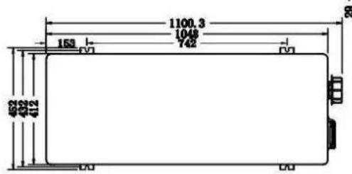
| Dimensions (L × P × H) | 1049×375×551 mm to 1100×452×1280 mm depending on model |
| Net weight | 52 kg to 128 kg depending on model |
| Main functions | Smart, Powerful, Silent modes, automatic defrost, anti-freeze protection |
| Control | Remote LED controller with temperature display |
| Safety | High/low pressure protection, water flow protection, freeze protection, automatic shutdown |
| Maintenance | Regular evaporator cleaning, winter drainage, protective cover |
| Warranty | 2 years (applicable conditions) |
Frequently Asked Questions - Bering ASTRALPOOL
User questions about Bering ASTRALPOOL
0 question about this device. Answer the ones you know or ask your own.
Ask a new question about this device
Download the instructions for your Pool in PDF format for free! Find your manual Bering - ASTRALPOOL and take your electronic device back in hand. On this page are published all the documents necessary for the use of your device. Bering by ASTRALPOOL.
USER MANUAL Bering ASTRALPOOL
Swimming Pool Heat Pump
User and Service manual
EN SWIMMING POOL HEAT PUMP User and service manual
FR POMPE A CHALEUR POUR PISCINE Manuel d'installation et d'utilisation
NL ZWEMBAD WARMTEPOMP Gebruiker en service manual
ES BOMBA DE CALOR PARA PISCINA Manual del usuario y de servicios
DE SCHWIMMBAD-WÄRMEPUMPE Benutzer- und Wartungshandbuch
IT PISCINA POMPAP DI CALORE Istruzioni per l'uso e di servizio
PT BOMBA DE CALOR DE PISCINA Manual do usuario e service
- Operators of equipment that contains fluorinated greenhouses gases in quantities of 5 tons of CO_2 , equivalent or more and not contained in foams shall ensure that the equipment is checked for leaks.
- For equipment that contains fluorinated greenhouse gases in quantities of 5 tons of equivalent or more, but of less than 50 tons of CO _2 equivalent: at least every 12 months.
Picture of the equivalenceo,
- Load in kg and Tons amounting. CO
| Load and Tons amounting \( {\mathrm{o}}_{2} \) | Frequency of test |
| From 7 at \( {75}\mathrm{\;{kg}} \) load \( = \) from 5 at 50 Tons | Each year |
Do no release R32 coolant liquid into the atmosphere. This is a fluoride greenhouse effect gas covered Kyoto agreement with a global warming potential (GWP) = 675 - (see the European Community reg on fluoride greenhouse effect gases Regulation (EU) No 517/2014).
Concerning the Gas R32, 7.40kg amounting at 5 to 10‰ commitment to check each year.
Training and certification
- The operator of the relevant application shall ensure that the relevant personnel have obtained the necessary certification, which implies appropriate knowledge of the applicable regulations and standards as well as the necessary competence in emission prevention and recovery of fluorinated greenhouse gases and handling safety the relevant type and size of equipment.
Record keeping
- Operators of equipment which is required to be checked for leaks, shall establish and maintain records for each piece of such equipment specifying the following information:
a) The quantity and type of fluorinated greenhouse gases installed;
b) The quantities of fluorinated greenhouse gases added during installation, maintenance or servicing or due to leakage;
c) Whether the quantities of installed fluorinated greenhouse gases have been recycled or reclaimed, including the name and address of the recycling or reclamation facility and, where applicable, the certificate number;
d) The quantity of fluorinated greenhouse gases recovered
e) The identity of the undertaking which installed, serviced, maintained and where applicable repaired or decommissioned the equipment, including, where applicable, the number of its certificate;
f) The dates and results of the checks carried out;
g) If the equipment was decommissioned, the measures taken to recover and dispose of the fluorinated greenhouse gases.
- The operator shall keep the records for at least five years, undertakings carrying out the activities for operators shall keep copies of the records for at least five years.
Formation et certification
1.Description
2. Transport information
3. Specifications
4. Accessories and options
5. Location and connection
6. Electrical Wiring
7. Start-up of the Heat Pump
8. Troubleshooting
9. Exploded Diagram
10. Maintenance
Thank you for using BERING swimming pool heat pump for your pool heating, it will heat your pool water and keep the constant temperature when the air ambient temperature is at -7 to 43^ .

ATTENTION: This manual includes all the necessary information for the use and the installation of your
heat pump.
The installer must read the manual and follow the instructions of implementation and maintenance.
The installer is responsible for the installation of the product and should follow all the instructions of the manufacturer and the regulations in application. Incorrect installation will invalidate the guarantee.
The manufacturer declines any responsibility for the damage caused by any third party, object ingression and of the errors due to the installation that do not follow the manual guidelines. Any use that is not as intended by the manufacturer will invalidate the guarantee.

WARNING:
Important notice:
Please always keep the heat pump in a well ventilated place and away from anything which could cause fire.
- Do not braze or weld the pipe if there is refrigerant inside machine. Please do not charge the gas when in a confined space.
- Please always empty the water in heat pump during winter time or when the ambient temperature drops below 0^ C , or else the Titanium exchanger will be damaged because of being frozen, in such case, your warranty will be lost.
Please always cut the power supply if you want to open the cabinet to reach inside the heat pump.
Please keep the display controller in a dry area to protect the display controller from being damaged by humidity.
Action of filling gas must be conducted by professional with R32 operating license.
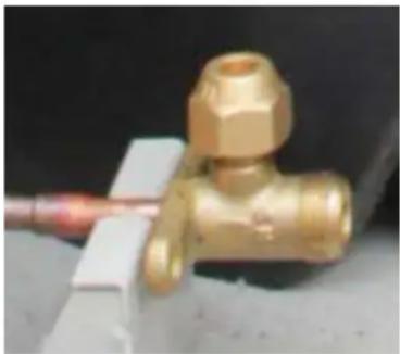
- Please fill the R32 gas from the globe valve inside machine.
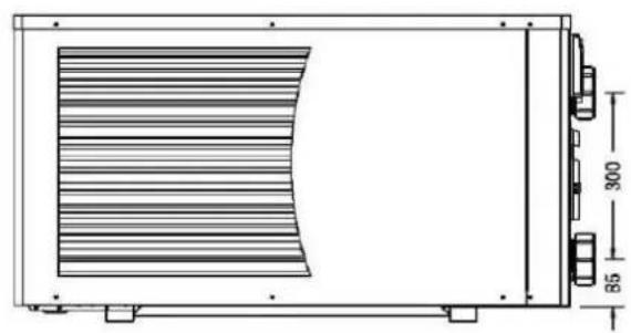
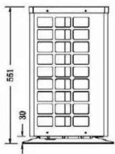
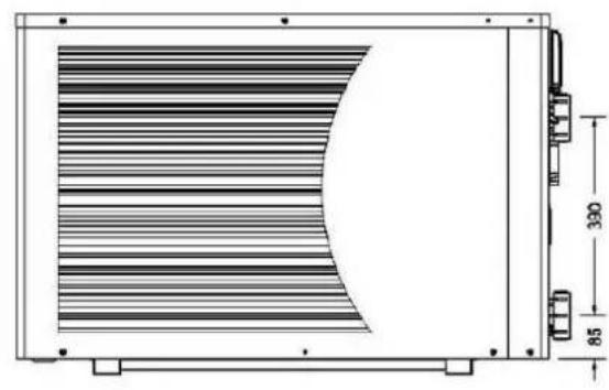
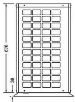
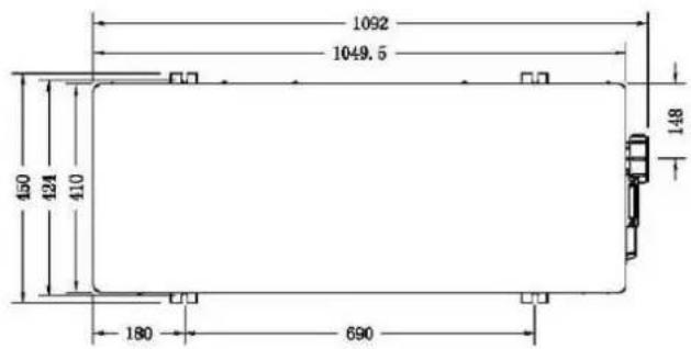
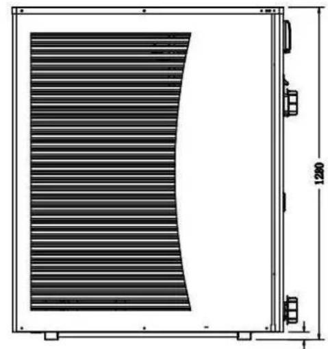
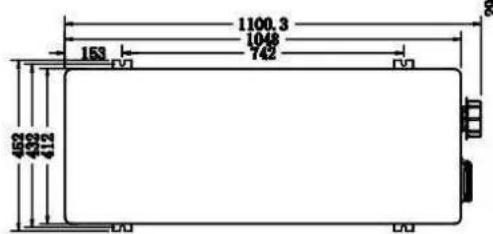
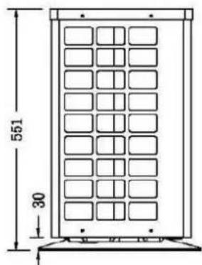
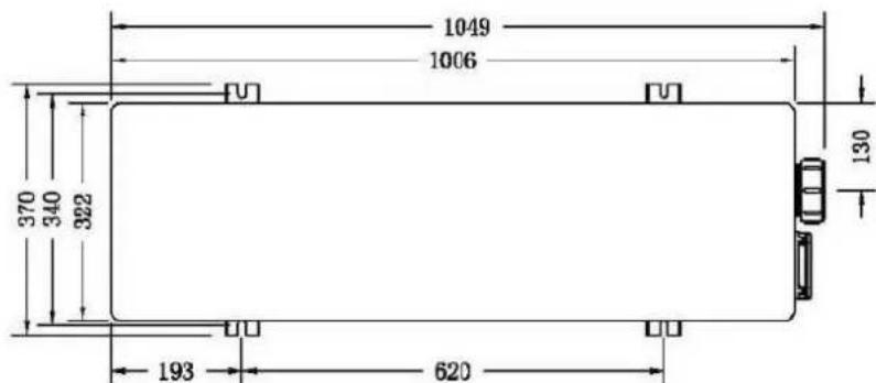
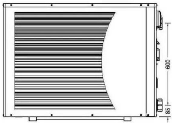
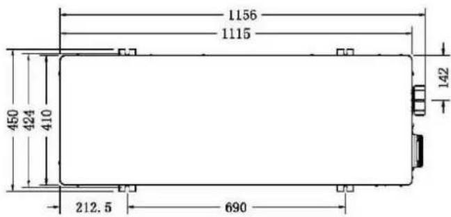
1. Dimension
1.1 Included with your Heat Pump
Water connection assembly 50~mm (pcs: 2)
-User and service manual
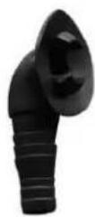
- Reducer connection
- 10 meters' signal wire
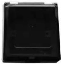
- Waterproof box
- Winter cover
- Anti-vibration base (pcs: 4)
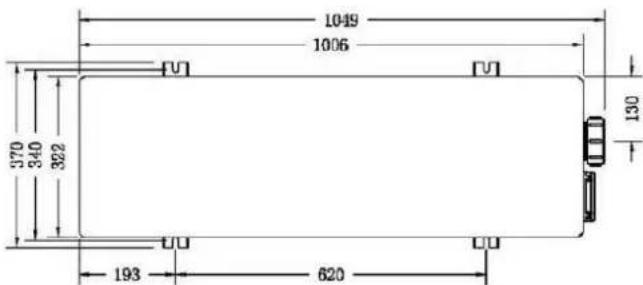
1.2 Dimension
BEXP05i/BEXP07i/BEXP09i
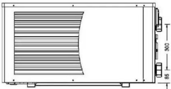

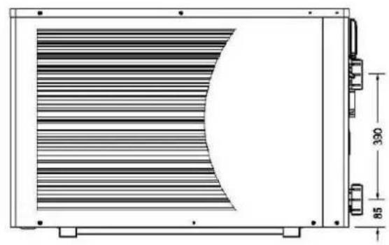
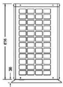

BEXP20i


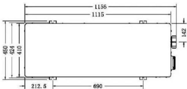
BEXP25i/BEXP30i


2. Transport information
2.1 Delivery of the unit

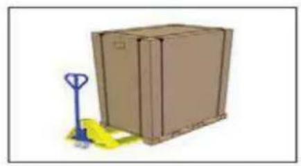
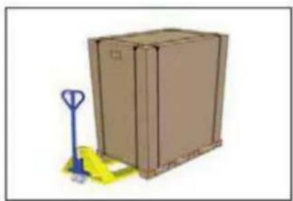
For the transportation, the heat pumps are fixed on the pallet and covered with a cardboard box. To protect from any damage, the heat pump must be transferred in its package.
It is the responsibility of the addressee to notify of any damage incurred during delivery within 48 hours.
responsibility can be taken once the unit has been signed for.
2.2 Stock advice

- The warehouse should be bright, spacious, open, well ventilated, have Fan equipment and no fire source.
- Heat pumps must be stored and transferred in vertical position in its original packaging. If it is not the cannot be operated until a minimum period of 24H has passed before the unit can have the electrical pow on.

FORBIDDEN
2.3 Transfer to the final position
-
During the unpacking of the product and the transfer from the pallet to the final place of installation, i necessary to maintain the heat pump in a verticalposition.
-
Smoking and the use of flames are prohibited near R32machine.
-
Water connection are not to be used as load bearing handles. The manufacturer would not take the responsibility in case of damage to the water pipes.
3. Specifications
3.1 Technical data BERING Inverboost heat pumps
CE Standard, R32, Steel Cabinet
| Model | BEXP05i | BEXP07i | BEXP09i | BEXP11i | BEXP14i | |
| * Performance at Air 28°C, Water 28°C, Humidity 80% | ||||||
| Heating capacity | kW | 5-3.2 | 7-3.3 | 9-3.5 | 11-4.8 | 14-5 |
| Power consumption | kW | 0.98-0.43 | 1.32-0.43 | 1.61-0.43 | 1.96-0.6 | 2.5-0.63 |
| C.O.P. | 7.4-5.1 | 7.7-5.3 | 8.5-5.6 | 8.5-5.6 | 8.5-5.6 | |
| * Performance at Air 15°C, Water 26°C, Humidity 70% | ||||||
| Heating capacity | kW | 3.7-2.3 | 4.7-2.4 | 6.6-2.5 | 7.9-3.5 | 9.5-3.6 |
| Power consumption | kW | 0.93-0.43 | 1.18-0.43 | 1.65-0.43 | 1.98-0.6 | 2.38-0.62 |
| C.O.P. | 5.4-4 | 5.6-4 | 5.8-4 | 5.8-4 | 5.8-4 | |
| * Performance at Air 0°C, Water 26°C, Humidity 78% | ||||||
| Heating capacity | kW | 2.76-1.7 | 3.5-2.0 | 4.50-2.3 | 5.5-3.0 | 7-3.2 |
| Power consumption | kW | 0.99-0.40 | 1.25-0.48 | 1.61-0.55 | 1.96-0.71 | 2.5-0.76 |
| C.O.P. | 4.2-2.8 | 4.2-2.8 | 4.2-2.8 | 4.2-2.8 | 4.2-2.8 | |
| Compressor type | MITSUBISHI INVERTER COMPRESSOR | |||||
| Voltage | V | 220~240V / 50Hz or 60Hz /1PH | ||||
| Rated current | A | 4.40 | 5.90 | 7.20 | 8.70 | 11.00 |
| Minimum fuse | A | 7.00 | 9.00 | 11.00 | 13.00 | 17.00 |
| Advised pool volume | m³ | 0-15 | 10-25 | 15-30 | 20-60 | 20-66 |
| Advised water flux | m³/h | 2.50 | 2.50 | 2.80 | 3.70 | 4.00 |
| Water pressure drop | Kpa | 12 | 12 | 12 | 14 | 15 |
| Heat exchanger | Twist-titanium tube in PVC | |||||
| Water connection | mm | 50 | ||||
| No. of Fan | 1 | |||||
| Fan speed | RPM | 650-870 | 650-850 | |||
| Power input of Fan | W | 80 | 200 | |||
| Noise level(10m) | dB(A) | 36-42 | 37-42 | 37-43 | 39-45 | 40-46 |
| Noise level(1m) | dB(A) | 44-51 | 45-52 | 45-52 | 46-54 | 47-56 |
| Refrigerant (R32) | g | 400 | 500 | 650 | 750 | 950 |
| CO2 equivalent | Tonne | 0.27 | 0.34 | 0.44 | 0.51 | 0.64 |
| Net weight | kg | 52.00 | 54.00 | 56.00 | 68.00 | 73.00 |
| Gross weight | kg | 64.00 | 66.00 | 68.00 | 73.00 | 78.00 |
| Net dimension | mm | 1049*375*551 | 1086*450*693 | |||
| Packing dimension | mm | 1110*430*705 | 1140*495*855 | |||
CE Standard, R32, Steel Cabinet
| Model | BEXP16i | BEXP18i | BEXP20i | BEXP25i | BEXP30i | |
| * Performance at Air 28℃, Water 28℃, Humidity 80% | ||||||
| Heating capacity | kW | 16-5.3 | 17.5-5.3 | 19-4.7 | 24-5.9 | 28.5-6.8 |
| Power consumption | kW | 2.85-0.66 | 3.21-0.66 | 3.39-0.59 | 4.29-0.74 | 5.09-0.85 |
| C.O.P. | 8.5-5.6 | 8.5-5.6 | 8.5-5.6 | 8.5-5.6 | 8.5-5.6 | |
| * Performance at Air 15℃, Water 26℃, Humidity 70% | ||||||
| Heating capacity | kW | 11.2-3.8 | 12.5-3.8 | 14-3.9 | 17.2-4.7 | 22.8-5.6 |
| Power consumption | kW | 2.8-0.66 | 3.12-0.66 | 3.5-0.67 | 4.3-0.81 | 5.7-0.97 |
| C.O.P. | 5.8-4 | 5.8-4 | 5.8-4 | 5.8-4 | 5.8-4 | |
| * Performance at Air 0℃, Water 26℃, Humidity 78% | ||||||
| Heating capacity | kW | 7.11-4.1 | 8.15-4.45 | 9.3-4.8 | 12-6.7 | 15.1-8.5 |
| Power consumption | kW | 2.54-0.95 | 2.91-1.03 | 3.32-1.09 | 4.29-1.53 | 5.34-1.95 |
| C.O.P. | 4.3-2.8 | 4.3-2.8 | 4.4-2.8 | 4.4-2.8 | 4.4-2.8 | |
| Compressor type | MITSUBISHI INVERTER COMPRESSOR | |||||
| Voltage | V | 220~240V / 50Hz or 60Hz /1PH | ||||
| Rated current | A | 11.90 | 14.30 | 15.00 | 19.00 | 22.60 |
| Minimum fuse | A | 18.00 | 22.00 | 23.00 | 29.00 | 34.00 |
| Advised pool volume | m³ | 30-85 | 30-90 | 55-120 | 65-130 | 75-180 |
| Advised water flux | m³/h | 4.60 | 5.00 | 5.00 | 8.00 | 10.00 |
| Water pressure drop | Kpa | 15 | 15 | 18 | 20 | 25 |
| Heat exchanger | Twist-titanium tube in PVC | |||||
| Water connection | mm | 50 | ||||
| No. of Fan | 1 | 2 | ||||
| Fan speed | RPM | 650-850 | 450-650 | (650-850)*2 | ||
| Power input of Fan | W | 200 | 150 | 200*2 | ||
| Noise level(10m) | dB(A) | 40-46 | 40-46 | 42-48 | 42-49 | 42-51 |
| Noise level(1m) | dB(A) | 47-56 | 47-56 | 49-58 | 49-59 | 50-60 |
| Refrigerant (R32) | g | 1100 | 1300 | 1500 | 1800 | 2300 |
| CO2 equivalent | Tonne | 0.74 | 0.88 | 1.01 | 1.22 | 1.55 |
| Net weight | kg | 78.00 | 80.00 | 98.00 | 117.00 | 128.00 |
| Gross weight | kg | 83.00 | 85.00 | 113.00 | 135.00 | 146.00 |
| Net dimension | mm | 1086*450*693 | 1118*455*860 | 1100*452*1280 | ||
| Packing dimension | mm | 1140*495*855 | 1215*510*1015 | 1156*500*1425 | ||
- Above data are subjects to modification without notice.
4. Accessories and options
4.1 Accessories list

Anti-vibration base, 4 pcs
Draining plug, 2 pcs
Waterproof box, 1 pc
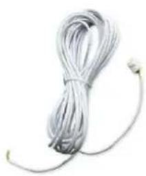
10M Signal wire, 1 pc

Water connection assembly, 2 sets

Winter Cover,1 pc
4.2 The Kit By-Pass
The By-Pass Kit is the essential accessory for the installation of your heat pump, it is also a tool for the optimization of the heating of the water. The valves allow the optimum flow of water using a manometer to make sure the optimized running of the compressor, see paragraph 5.6 controls of the pressure.

4.3 Accessories Installation
Anti-vibration bases
- Take out 4 Anti-vibration base
- Install them on the bottom of machine.
Draining plug
- Install the draining plug under bottom panel
- Connect with a water pipe to out the water.
Note: Lift the heat pump to insthe. Never overturn the heat pum could damage the compressor.
Water Inlet & outlet connection
- Install the two joints like the picture shows
- Screw them onto the water In outlet connection
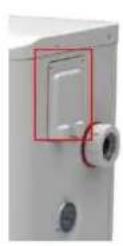
Mains Cable wiring
- Open the cover of the terminal (marked red) on the side of mac
2.Tight the cables in the correct connections, L N E, inside the terminal block.
Filtration pump wiring (Dry contact)
- Open the cover of the terminal (marked red) on the side of mac
- Tight the cables in the correct connections, 1 2, inside the term block.
5. Location and connection
ATTENTION:
Please observe the following rules when installing the heat pump:
- Any addition of chemicals must take place in the piping located downstream from the heat pump.
- Always keep the heat pump upright. If the unit has been held at an angle, wait at least 24 hours before applying mains power to the heat pump.
5.1 Heat pump location
The unit will work properly in any desired location as long as the following three items are present:
-
Fresh air
-
Electricity
-
Swimming pool filters
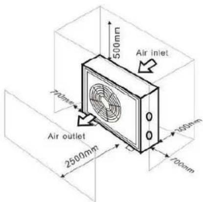
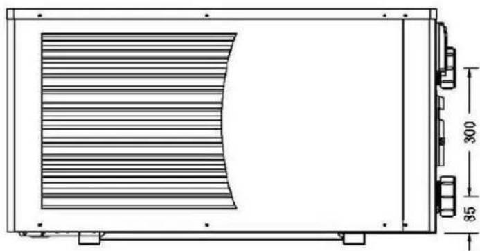
The unit may be installed in virtually any outdoor location as long as the specified minimum distances to other objects are maintained (see drawing below). Please consult your installer for installation with an indoor pool. Installation in a windy location does not present any problem at all.
ATTENTION:
Never install the unit in a closed room with a limited air volume in which the air expelled from the unit will be reused, or close to shrubbery that could block the air inlet. Such locations impair the continuous supply of fresh air, resulting in reduced efficiency and possibly preventing sufficient heat output.
See the drawing below for minimum dimensions.

5.2 Check-valve installation

NOTE
Note: If automatic dosing equipment for chlorine and acidity (pH) is used, it is essential to protect the pump against excessively high chemical concentrations which may corrode the heat exchanger. For this r equipment of this sort must always be fitted in the piping on the downstream side of the heat pump, and it is recommended to install a check-valve to prevent reverse flow in the absence of water circulation.
Damage to the heat pump caused by failure to observe this instruction is not covered by the warranty.

5.3 Typical arrangement

Note: This arrangement is only an illustrative example

NOTE
The factory supplies only the heat pump. All other components, including a bypass if necessary, must be provided by the user or the installer.
ATTENTION:
In order to heat the water in the pool (or hot tub), the filtration pump must be running to cause the water to circulate through the heat pump. The heat pump will not start up if the water is not circulating.
6. Electrical Wiring
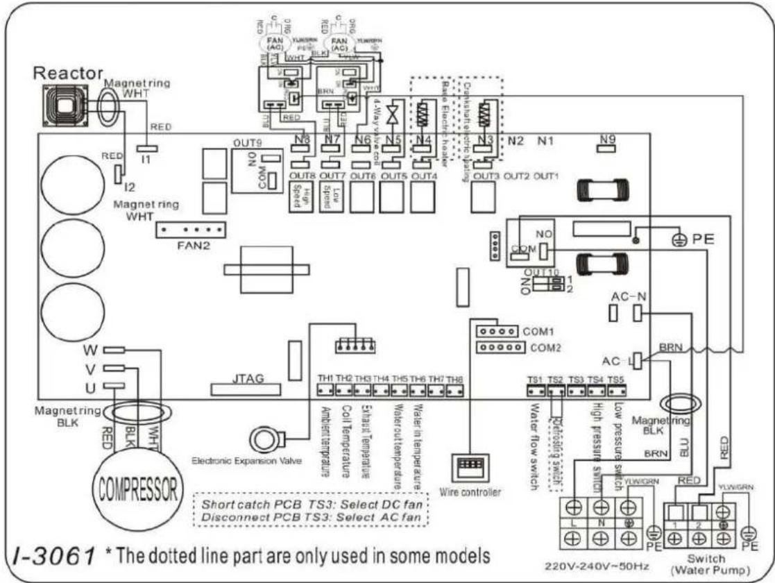
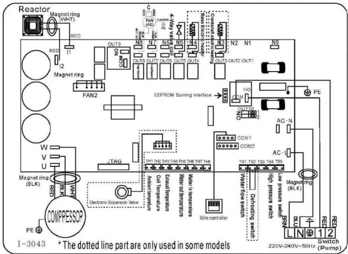
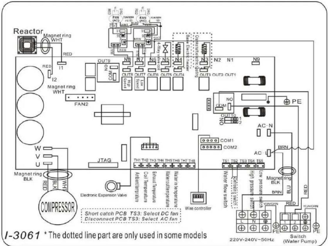
6.1 Swimming pool heat pump wiring diagram
Ref: BEXP05i/BEXP07i/BEXP09i/BEXP11i/BEXP14i/BEXP16i/BEXP18i/BEXP20i

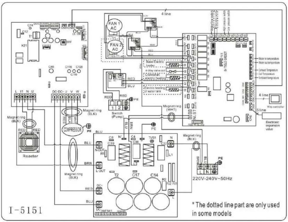
Ref: BEXP30i

NOTE:
(1) Above electrical wiring diagram only for your reference, please subject machine posted the wiring diagram.
(2) The swimming pool heat pump must be connected ground wire well, although the unit heat exchanger is electrically isolated from the rest of the unit. Grounding the unit is still required to protect you against short circuits inside the unit. Bonding is also required.
Disconnect: A disconnect means (circuit breaker, fused or un-fused switch) should be located within sight of and readily accessible from the unit. This is common practice on commercial and residential heat pumps. It prevents remotely-energizing unattended equipment and permits turning off power at the unit while the unit is being serviced.
6.2 Electrical protection
The power supply for the heat pump must come, preferably, from an exclusive circuit with regulatory protection components (30mA differential protection) and a magneto-thermal switch.
- The electrical installation must be carried out by a specialized professional (electrician) in accordance with the standards and regulations in force in the country of installation.
- The heat pump circuit must be connected to a safety earth circuit at the terminal block.
- The cables must be properly installed to prevent interference.
- The pump is intended for connection to a general power supply with earth connection.
- Section of the cable; This section is indicative and should be checked and adapted according to the needs and conditions of use.
- The tolerance of acceptable voltage variation is + / - 10% during operation.
The connections must be dimensioned according to the power of the device and the state of installation.
| Models | Circuit breaker | Maximum length of the wire | |||
| 2,5 mm² | 4 mm² | 6 mm² | 10 mm² | ||
| BEXP05i | 7A | 84m | 135m | 200m | 335m |
| BEXP07i | 7A | 84m | 135m | 200m | 335m |
| BEXP09i | 9A | 57m | 90m | 130m | 225m |
| BEXP11i | 11A | 57m | 90m | 130m | 225m |
| BEXP14i | 14A | 43m | 68m | 100m | 170m |
| BEXP16i | 16A | 34m | 54m | 80m | 135m |
| BEXP18i | 18A | 32m | 50m | 75m | 128m |
| BEXP20i | 20A | 29m | 45m | 66m | 110m |
| BEXP25i | 25A | / | 35m | 52m | 95m |
| BEXP30i | 35A | / | / | 40m | 75m |
These values are given as a guideline, only an authorised electrician can determine the value corresponding to your installation. The electric cable must be equipped with a ground connection and with a circuit breaker with difference 30mA .
6.3 Installation of the display deportee
Photo(1) Photo(2) Photo(3) Photo(4) Photo(5)
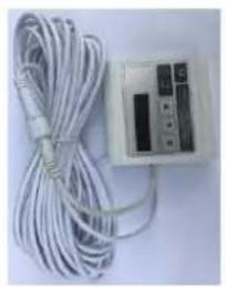


- The end with plug connects with the control panel (photo1)
- The other end of the signal wire. (photo2)
- Open the cover of the terminal boxl and pass through it the cable of the remote screen. (photo3,4)
- Insert the wiring into the designated position (code:COM 1 or COM-L) on the PC board. (photo5)
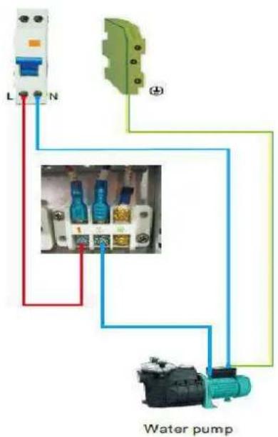
6.4 Connection to pilot the water pump
Dry contact timer connection
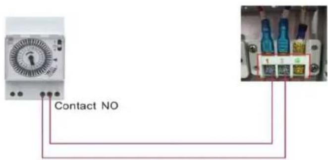
Dry contact pump connection
7. Initial operation
7.1 Initial operation
Note: In order to heat the water in the pool (or hot tub), the filter pump must be running to cause the water to circulate through the heat pump. The heat pump will not start up if the water is not circulating.
After all connections have been made and checked, carry out the following procedure:
- Switch on the filtration pump. Check for leaks and verify that water is flowing from and to the swimming pool.
- Connect power to the heat pump and press the On/Off button on the electronic control panel. The unit will start up after the time delay expires (see below).
- After a few minutes, check whether the air blowing out of the unit is cooler.
- When turn off the filtration pump, the unit should also turn off automatically, if not, then adjust the flow switch.
- Allow the heat pump and the filter pump to run 24 hours a day until the desired water temperature is reached. The heat pump will stop running at this point +1^ . After this, it will restart automatically (as long as the filtration pump is running) whenever the swimming pool water temperature drops 1 degree below the set temperature (for example, if you set the temperature 28^ , the heat pump will stop when the temperature at 29^ . While it will restart when the temperature of the water down to 27^ )
Depending on the initial temperature of the water in the swimming pool and the air temperature, it may take several days to heat the water to the desired temperature. A good swimming pool cover can dramatically reduce the required length of time.

NOTE
Water Flow Switch:
It is equipped with a flow switch for protecting the HP unit running with adequate water flow rate. It will turn on when the filtration pump runs and shut it off when the pump shuts off. If the pool w h er than 1 m above or below the heat pump's automatic adjustment knob, your dealer may need to initial startup.
1 m above or below the heat pump's automatic adjustment knob, your dealer may need to adjust its initial startup.
Time delay - The heat pump has a built-in 3-minute start-up delay to protect the circuitry and avoid excessive contact wear. The unit will restart automatically after this time delay expires. Even a brief power interruption will trigger this time delay and prevent the unit from restarting immediately. Additional power interruptions during this delay period do not affect the 3-minute duration of the delay.
7.2 Condensation
The air drawn into the heat pump is strongly cooled by the operation of the heat pump for heating the pool water which may cause condensation on the fins of the evaporator.

NOTE
The amount of condensation may be as much as several litres per hour at high relative humidity. The condensate will drain from the bottom of the heat pump. This is sometimes mistakenly regarded as a very leak.
7.3 Pressure gauge display (R32)
Examine the pressure gauge which indicates the refrigerant gas pressure of the unit, the below table shows the normal value of the gas pressure (R32) when the machine is in power off or running conditions.
| Unit Condition | Power Off | |||
| Ambient (℃) | -5~5 | 5~15 | 15~25 | 25~35 |
| Water temp (℃) | / | / | / | / |
| Pressure gauge (Mpa) | 0.59~0.85 | 0.85~1.18 | 1.18~1.59 | 1.59~2.1 |
| Unit Condition | Running | ||||
| Ambient (℃) | / | / | / | / | / |
| Water temp (℃) | 10~15 | 15~20 | 20~25 | 25~30 | 30~35 |
| Pressure gauge (Mpa) | 1.1~1.6 | 1.3~1.8 | 1.5~2.1 | 1.7~2.4 | 1.9~2.7 |
7.4 Display Controller Operation

NOTE: When the heat pump connects to the power, the LED display shows a code for 3 seconds which indicates the heat pump model.
7.4.1 button
Press to start the heat pump unit, the LED display shows the desired water temperature for 5 seconds, then shows the inlet water temperature and the operation mode.
Press to stop the heat pump unit and show "OFF"
Notice : During the parameter checking and setting, press the to quick-exit and save the current setting .
Press again to turn on/off the machine.
7.4.2 button
Automatic mode:
There are 3 modes for the unit, Heating only, Auto mode (heating and cooling switch), Cooling only.
You can switch Heating only and Auto mode by pressing for 5 seconds, no matter the unit is on or off. (default: Smart mode)
Press for 5 seconds again to exit automatic mode and switch to heating mode (default: Smart mode)
Note: Under Automatic mode, it is useless to set parameter P1.
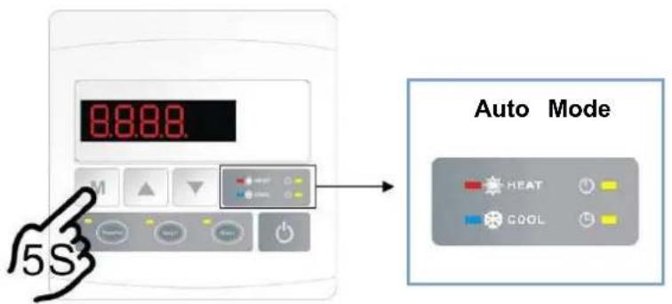

Operation logic of Auto Mode:

Lock/Unlock the display:
Hold and for 5 seconds to lock/unlock the display.
Water temperature setting:
Press or to set the water temperature directly.
Parameter checking:
Press first, then press to check the
| Code | Condition | Scope | Remark |
| d0 | IPM mould temperature | 0-120°C | Real testing value |
| d1 | Inlet water temp. | -9°C~99°C | Real testing value |
| d2 | Outlet water temp. | -9°C~99°C | Real testing value |
| d3 | Ambient temp. | -30°C~70°C | Real testing value |
| d4 | Frequency limitation code | 0,1,2,4,8,16 | Real testing value |
| d5 | Piping temp. | -30°C~70°C | Real testing value |
| d6 | Gas Discharge temperature | 0°C~C5°C (125°C) | Real testing value |
| d7 | Step of EEV | 0~99 | N*5 |
| d8 | Compressor running frequency | 0~99Hz | Real testing value |
| d9 | Compressor current | 0~30A | Real testing value |
| d10 | Current fan speed | 0-1200 (rpm) | Real testing value |
| d11 | Error code for last time | All error code |
Remark: d4: Frequency limitation code, 0: No frequency limit,
1: Coil pipe temperature limit, 2: Overheating or overcooling frequency limit,
4: Drive Current frequency limit, 8: Drive voltage frequency limit,
16: Drive high temperature frequency limit.
If needed, press second, then press or to adjust the current parameter.
(for example: Press first, then press to enter parameter P7 checking, and press second, then
press or to adjust the parameter P7 Inlet water temp. Correction from -9 to 9.)
| Code | Name | Scope | Default | Remark |
| P0 | Mandatory | 0-1 | 0 | 0: Default normal operation |
| P1 | Working mode | 0-1 | 1 | 1: Heating mode, 0: cooling mode, |
| P2 | Timer on/off | 0-1 | 0 | 1 Timer on/off is under function 0 Timer on/off is out of function (The setting of P5 and P6 won't work) |
| P3 | Water pump | 0-1 | 0 | 1: Always running; |
| P4 | Current time | HH:M | 00: 00 | 0-23:0-59 |
| P5 | Timer on | HH:M | 00: 00 | 0-23:0-59 |
| P6 | Timer off | HH:M | 00: 00 | 0-23:0-59 |
| P7 | Water temp. | -9~9 | 0 | Default setting: 0 |
NOTE: Under defrosting mode, P0 = 1 . After defrosting finished, it will be automatic enter Normal mode, P0 = 0 .
7.4.4 System reset function
Press and in 10s, the system will reset and display "0000" on the controller.
7.4.5
Symbol of heating, the light will be on when it is in operation.
When defrosting, the light will flash.
7.4.6

Symbol of cooling, the light will be on when it is in operation.
Note: When parameter P1 is on checking/adjusting,
7.4.7

Symbol of automatic stop, the light will be on when it is in operation.
7.4.8

Symbol of automatic start, the light will be on when it is in operation.
7.4.9

Press this button, the light will be flash, the heat pump will operate in 'Full output' only.
7.4.10

While you choose the Smart, the heat pump will just operate in 'Medium output' and 'Full output'
When in 'Medium output', the light of Smart will flash.
When in 'Full output', the lamp of Smart is lit, the lamp of Powerful will be flash.
7.4.11

While you choose the Silent, the heat pump will just operate in 'Medium output' and 'Small output'
When in 'Small output', the lamp of Silent will flash.
When in 'Medium output', the lamp of Silent is lit, the lamp of Smart will flash.
7.5 Heating operation logic
| Working status | Working mode | Water in temperature-T1 | For example, water in temperature-T1 | Heat pump working level | |
| 1 | Start-up of heat pump | When you select the "Smart working mode" | T1<Tset-1 | T1< 27°C | Powerful mode-frequency F |
| 2 | Tset-1≤T1 < Tset | 27°C ≤ T1 <28°C | Frequency: F9 -F8-F7,...-F2 | ||
| 3 | Tset≤ T1 <Tset+ | 28°C ≤ T1 <29°C | Silent mode-frequency F2 | ||
| 4 | T1≥Tset+1 | T1≥29°C | HP will be in Standby, s working until the water temperature drops to less 28°C. | ||
| 5 | When you select the "Silent working mode". | T1<Tset | T1< 28°C | Smart mode -frequency F5 | |
| 6 | Tset≤T1 < Tset+1 | 28°C ≤ T1 < 29°C | Silent mode-frequency F2/F1. | ||
| 7 | T1≥Tset+1 | T1≥29°C | HP will be in Standby, s working until the water temperature drops to less 28°C. | ||
| 8 | When you select the "Powerful working mode." | T1<Tset+1 | T1<29°C | Powerful mode-frequency F10/F9 | |
| 9 | T1≥ Tset+1 | T1≥29°C | HP will be in Standby, s working until the water temperature drops to less 28°C. | ||
| 10 | Re-start to heat water in standby status | When HP is working at "Smart mode" | T1≥Tset | T1≥28°C | Standby |
| 11 | Tset>T1≤Tset-1 | 28°C >T1 ≥ 27°C | Silent-frequency F2 | ||
| 12 | Tset-1> T1≥Tset-2 | 27°C >T1 ≥ 26°C | Frequency: F2-F3-F4,...-F9 | ||
| 13 | <Tset-2 | <26°C | Powerful-frequency F9 | ||
| 14 | When HP is working at "Silent mode" | ≥Tset | ≥28°C | Standby | |
| 15 | Tset>T1≤Tset-1 | 28°C >T1 ≥ 27°C | Silent mode-frequency F2/F | ||
| 16 | T1<Tset-1 | T1<27°C | Smart -frequency F5 | ||
| 17 | When HP is working at "Powerful mode" | T1<Tset-1 | T1<27°C | Powerful -frequency F10/F9 | |
7.6 Cooling operation logic
| Working status | Working mode | Water in temperature | For example, water in temperature | Heat pump working level | |
| 1 | Start-up of heat pump | When you select the "Smart working mode" | T1≤Tset-1 | T1≤27°C | Standby. |
| 2 | Tset-1<T1≤Tset | 27°C < T1 ≤ 28°C | Silent mode-frequency F2 | ||
| 3 | Tset<T1≤Tset+1 | 28< T1≤29°C | frequency: F9 -F8-F7,...,- F2 | ||
| 4 | T1≥Tset+1 | T1≥29°C | Powerful mode-F9 | ||
| 5 | When you select the "Silent working mode". | T1≤Tset-1 | ≤27°C | Standby | |
| 6 | Tset-1<T1≤Tset | 27°C < T1 ≤ 28°C | Silent mode - frequency F2/F1 | ||
| 7 | T1>Tset | T1>28°C | Smart mode -frequency F5 | ||
| 8 | When you select the "Powerful working mode." | T1>Tset-1 | T1>27°C | Powerful mode-frequency F10/F9 | |
| 9 | T1≤Tset-1 | T1≤27°C | Standby | ||
| 10 | Re-start to cool water in standby status | Smart | T1≤Tset-1 | T1≤27°C | Standby |
| 11 | Tset≤T1 <Tset+1 | 28≤T1<29C | Silent- frequency F2 | ||
| 12 | Tset+1≤T1 <Tset+2 | 29≤T1<30°C | Frequency: F2 -F3-F4,...,- F9 | ||
| 13 | T1≥Tset+2 | T1≥30°C | Powerful mode -frequency F | ||
| 14 | Silent | Tset<T1≤Tset+1 | 28< T1≤29°C | Silent mode-frequency F2/F1 | |
| 15 | T1>Tset+1 | T1>29°C | Smart mode-frequency F5 | ||
| 16 | Powerful | T1>Tset+1 | T1>29°C | Powerful mode-frequency F10/F9 | |
| 17 | T1≤Tset-1 | T1≤27°C | Standby | ||
7.7 Water pump logic
Option 1: Water pump is related to heat pump operation to start or stop.
Filtration pump starts 60s before compressor, filtration pump starts 30s and then the water flow switch detects flow. When the heat pump enters standby mode, filtration pump will stop 60s after compressor stops.
Filtration pump will restart running for 3 minutes then stop when the standby time is over 2 hours.
| Condition | Example | Water pump working logic | |
| Heating mode | T1>Tset-1, last for 30 minutes | T1>27°C, last for 30 minutes | Filtration pump will enter standby mode for 2 and will not start except after manual power restart. Heat pump will restart 3 minutes after filtration pump exit the standby mode to detect water temp. T1 again. |
| Cooling mode | T1<Tset+1, last for 30 minutes | T1<29°C, last for 30 minutes | Filtration pump will enter standby mode for 2 and will not start except after manual power restart. Heat pump will restart 3 minutes after filtration pump exit the standby mode to detect water temp. T1 again. |
Option 2:
When the heat pump is on (running or standby), filtration pump will always be on. It will run for 1 minute after manually turn off.
NOTE:
Tset = Tsetting water temperature
For example : Tset = 28°C Tsetting water temperature in your pool heat pump
Tset-1 = less 1^ C than Tsetting temperature
Tset-1 = 28-1=27°C
Tset+1= more 1^ than Tseting temperature
Tset+1=28+1=29°C
7.8 Protection of the unit
Remarks:
- In heating mode, if the water out temperature is higher than the set temperature over 7^ , LED controller
displays EE04 for water over-heating protection.
- In cooling mode, if the water out temperature is lower than the set temperature over 7^ , LED controller displays PP11 for water over-cooling protection.

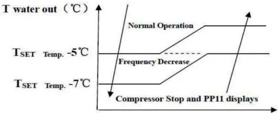
EE04 Water Overheating Protection
PP11 Water Overcooling Protection
For example as below:
| Mode | Output water temperature | Set Point temperature | Condition | Malfunction |
| Heating mode | 36°C | 29°C | Tout -Tset ≧ 7°C | EE04 Overheating protection for water temperature (T2) |
| Cooling mode | 23°C | 30°C | Tset -Tout ≧ 7°C | PP11 Too low protection for water temperature (T2) |
8.Troubleshooting
- 1 Error code display on LED wire controller
| Malfunction | Error code | Reason | Solution |
| Inlet water temperature sensor failure T1-TH6 | PP01 | 1. The sensor in open or short circ2. The wiring of sensor is loose | 1. Check or change the sensor2.Re-fix the wiring of the sensor |
| Outlet water temperature sensor failure T2-TH5 | PP02 | 1. The sensor in open or short circ2. The wiring of sensor is loose | 1. Check or change the sensor2.Re-fix the wiring of the sensor |
| Heating piping sensor failure T3-TH2 | PP03 | 1. The sensor in open or short circ2. The wiring of sensor is loose | 1. Check or change the sensor2.Re-fix the wiring of the sensor |
| Gas return sensor failure | PP04 | 1. The sensor in open or short circ2. The wiring of sensor is loose | 1. Check or change the sensor2.Re-fix the wiring of the sensor |
| Ambient temperature sensor failure T5-TH1 | PP05 | 1. The sensor in open or short circ2. The wiring of sensor is loose | 1. Check or change the sensor2.Re-fix the wiring of the sensor |
| Discharge piping sensor failure T6-TH3 | PP06 | 1. The sensor in open or short circ2. The wiring of sensor is loose | 1. Check or change the sensor2.Re-fix the wiring of the sensor |
| Antifreeze protection in Winter | PP07 | Ambient temperature or water inlet temperature is too low | Normal protection |
| Low ambient temperature protection | PP08 | 1.Beyond the scope of using environment2. Sensor abnormality | 1. Stop using, beyond the scope of using2.Change the sensor |
| Piping temperature too high protection under cooling mode T3-TH2 | PP10 | 1. Ambient temperature is too high or the water temperature is too high in cooling mode2. Refrigeration system is abnormal | 1. Check the scope of using2. Check refrigeration system |
| T2-TH5 water temp. Too low protection under cooling mode | PP11 | 1. Low water flow2. T2-TH5 temperature sensor abnormal | 1. Check filtration pump and waterway system2. Change T2-TH5 temperature sensor |
| High pressure failure TS4 | EE01 | 1. Ambient temperature is too high2. Water temperature is too high3. Water flow is too lowFan motor speed is abnormal or far motor has damaged | 1. Check the water flow or filtration pump2. Check the fan motor3. Check and repair the piping system |
| Low pressure failure TS5 | EE02 | 1. EEV has blocked or pipe system is jammed2. Motor speed is abnormal or motor has damaged3. Gas leakage | 1. Check the EEV and piping system Check the motor2. Through the high pressure gauge to check the pressure value Check refrigeration system |
| Water flow failure TS1 | EE03 Or” ON” | 1. Water flow switch is damaged2. No/ Insufficient water flow. | 1. Change the water flow switch2. Check the filtration pump or the waterway system |
| Over heating protection for water temperature (T2-TH5) in heating mode | EE04 | 1. Low water flow2. Water flow switch is stuck and the water supply is cut off3. T2-TH5 sensor is abnormal | 1. Check the water way system2. Check the filtration pump or water flow switch3. Check T2-TH5 sensor or replace |
| T6-TH3 Discharge too high protection | EE05 | 1.Lack of gas2.Low water flow3.Piping system has been blocked4.Dischargetemp. Sensor failure | 1. Check the high pressure gauge if too low, fill with some gas2. Check the waterway system an filtration pump3. Check the piping system if there was any block4. Change a new Discharge temp. sensor |
| Controller failure | EE06 | 1. Wire connection is not good, or damaged signal wire2. Controller failure | 1. Check and re-connect the signal wire2. Change a new signal wire3. Turn off electricity supply and restart machine4. Change a new controller |
| Compressor current protection | EE07 | 1. The compressor current is too large instantaneously2. Wrong connection for compressor phase sequence3.Compressor accumulations of liquid and oil lead to the current becomes larger4. Compressor or driver board damaged5. The water flow is abnormal6. Power fluctuations within a short time | 1. Check the compressor2. Check compressor phase3. Check if the power in the normal range4. Check the phase sequence connection5. Check the waterway system an filtration pump6. Check mains power input |
| Communication failure between controller and main board | EE08 | 1. Poor signal wire connection or damaged signal wire2. Controller malfunction | 1. Check and re-connect the signal wire2. Change a new signal wire3. Turn off electricity supply and restart machine4. Change controller |
| Communication failure between Main control board and Driving board | EE09 | 1. Poor connection of communication wire2. The wire is damaged | 1. Check the wire connection2. Change wire |
| VDC voltage too high protectio | EE10 | 1. Line voltage is too high2. Driver board is damaged. | 1. Check if the power is in th normal range2. Change driver board or ma board |
| IPM module protection | EE11 | 1. Data mistake2. Wrong compressor phase connection3. Compressor liquid and oil accumulation lead to the current becomes larger4. Compressor or driver board damaged | 1. Program error, turn off electricity supply and restart after 3 minutes2. Change driver board3. Check compressor sequence connection |
| VDC voltage too low protection | EE12 | 1. Mother line voltage is too low2. Driver board is damaged. | 1. Check if the power is in the normal range2. Change driver board |
| Input current over high protection. | EE13 | 1. The compressor current is too large momentary2. The water flow is abnormal3. Power fluctuations within a short time4. Wrong PFC inductor | 1. Check the compressor2. Check the waterway system3. Check if the power is in t normal range4. Check if the correct PFC inductor is used |
| IPM module thermal circuit is abnormal | EE14 | 1. Output abnormality of IPM module thermal circuit2. Fan motor is abnormal or damagedFan blade is broken | 1. Change a driver board2. Check if the motor speed too low or fan motor damaged, change it.3. Change fan blade |
| IPM module temperature too high protection | EE15 | 1. Output exception of IPM module thermal circuit2. Motor is abnormal or damaged3. Fan blade is broken | 1. Change a driver board2. Check if the fan motor speed too low or fan motor damaged, change it3. Change the fan blade |
| PFC module protection | EE16 | 1. Output exception of PFC module2. Motor is abnormal or damaged3. Fan blade is broken4. Input voltage leap, input power is abnormal | 1. Change a driver board2. Check if the motor speed is to low or fan motor damaged, change it3. Change the fan blade4. Check the input voltage |
| DC fan motor failure | EE17 | 1. DC motor is damaged2. Main board is damaged3. The fan blade is stuck | 1. Detect DC motor, replace with new one2. Change a new main board3. Find out the barrier and work out |
| PFC module thermal circuit is abnormal | EE18 | The driver board is damaged | 1. Change a new driver board2. Check if the fan motor speed too low or fan motor damaged, change it |
| PFC module high temperature protection | EE19 | 1. PFC module thermal circuit output abnormal2. Motor is abnormal or damaged3. Fan blade is broken4. The screw in the driver board is not tight | 1. Change a new driver board2. Check if the motor speed is to low or fan motor damaged, change it3. Change the fan blade4. Check if the screw is loose |
| Input power failure | EE20 | The supply voltage fluctuates too much | Check whether the voltage is stable |
| Software control exception | EE21 | 1. Compressor runs out of step 2. Wrong program 3. Impurity inside compressor causes the unstable rotate speed | 1. Check the main board or change a new one 2. Enter correct program |
| Current detection circuit failure | EE22 | 1. Voltage signal abnormal 2. Driver board is damaged | 1. Check the main board or change a new one 2. Change a new driver board |
| Compressor start failure | EE23 | 1. Main board is damaged 2. Compressor wiring error or poor contact or unconnected 3. Liquid accumulation inside 4. Wrong phase connection for compressor | 1. Check the main board or change a new one 2. Check the compressor wiring according to the circuit diagram Check the compressor or change a new one |
| Ambient Temperature device failure on Driver board | EE24 | Ambient Temperature device failure | Change driver board or main board |
| Compressor phase failure | EE25 | Compressors U, V, W are connected to one phase or two phases. | Check the actual wiring according to the circuit diagram |
| Four-way valve reversal failure | EE26 | 1. Four-way valve reversal failure 2. Lack of refrigerant (no detect when T3-TH2 or T5-TH1 malfunction) | 1. Switch to Cooling mode to check the 4-way valve if it has been reversed correctly 2. Change a new 4-way valve 3. Fill with gas |
| EEPROM data read malfunction | EE27 | 1. Wrong EEPROM data in the program or failed input of EEPROM data 2. Main board failure | 1. Re-enter correct EEPROM data 2. Change a new main board |
| The inter-chip communication failure on the main control board | EE28 | Main board failure | 1. Turn off electricity supply and restart it 2. Change a new main board |
8.2 Other Malfunctions and Solutions (No display on LED wire controller)
| Malfunctions | Observing | Reasons | Solution |
| Heat pump is not running | LED wire controller no display. | No power supply | Check cable and circuit breaker if it is connected |
| LED wire controller. Displays the actual time. | Heat pump under standby status | Startup heat pump to run. | |
| LED wire controller displays the actual water temperature. | 1. Water temperature is reaching to setting value, HP under constant temperature status. 2. Heat pump just starts to run. 3. Under defrosting. | 1. Verify water temperature setting. 2. Startup heat pump after a few minutes. 3. LED wire controller should display "Defrosting". | |
| Water temperature is cooling when HP runs under heating mode | LED wire controller displays actual water temperature and no error code displays. | 1. Choose the wrong mode. 2. Figures show defects. 3. Controller defect. | 1. Adjust the mode to proper running 2. Replace the defect LED wire controller, and then check the status after changing the running mode, verifying the water inlet and outlet temperature. 3. Replace or repair the heat pump u |
| Short running | LED displays actual water temperature, no error code displays. | 1. Fan NO running. 2. Air Fan is not enough. 3. Refrigerant is not enough. | 1. Check the cable connections between the motor and fan, if necessary, it should be replaced. 2. Check the location of heat pump u and eliminate all obstacles to make good air Fan. 3. Replace or repair the heat pump u |
| water stains | Water stains on heat pump unit. | 1. Concreting. 2. Water leakage. | 1. No action. 2. Check the titanium heat exchanger carefully if it is any defect. |
| Too much ice on evaporator | Too much ice on evaporator. | 1. Check the location of heat pump u and eliminate all obstacles to make good air Fan. 2. Replace or repair the heat pump u |
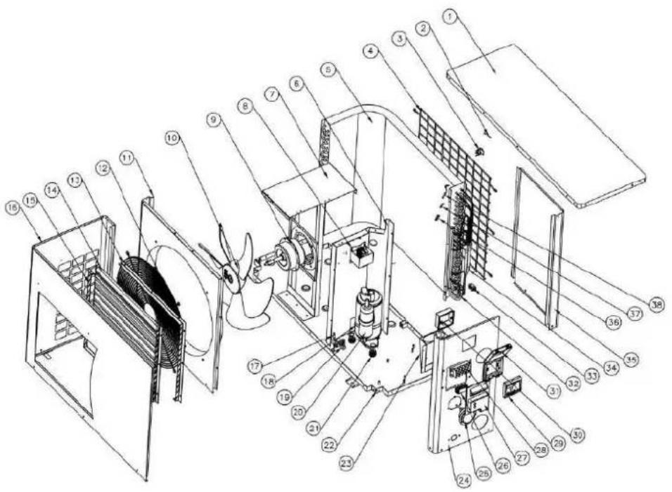
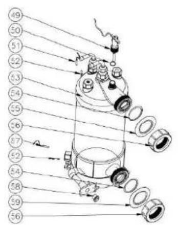
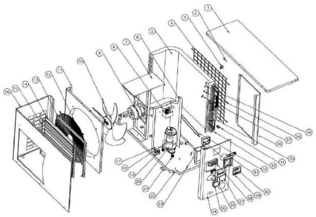
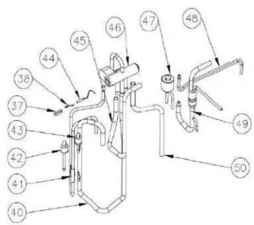
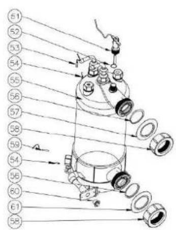
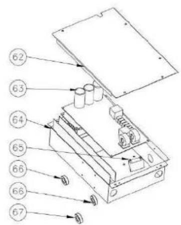
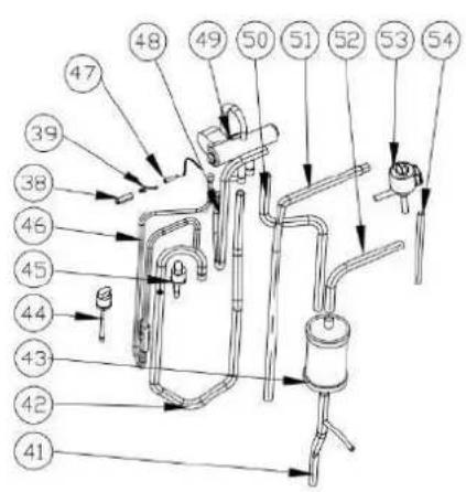
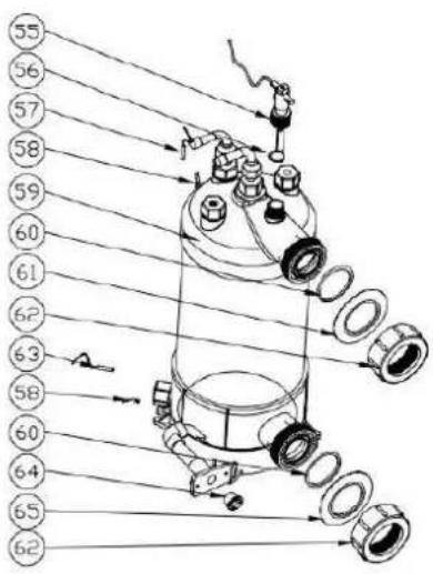
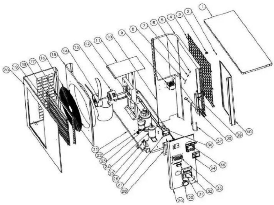
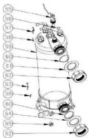
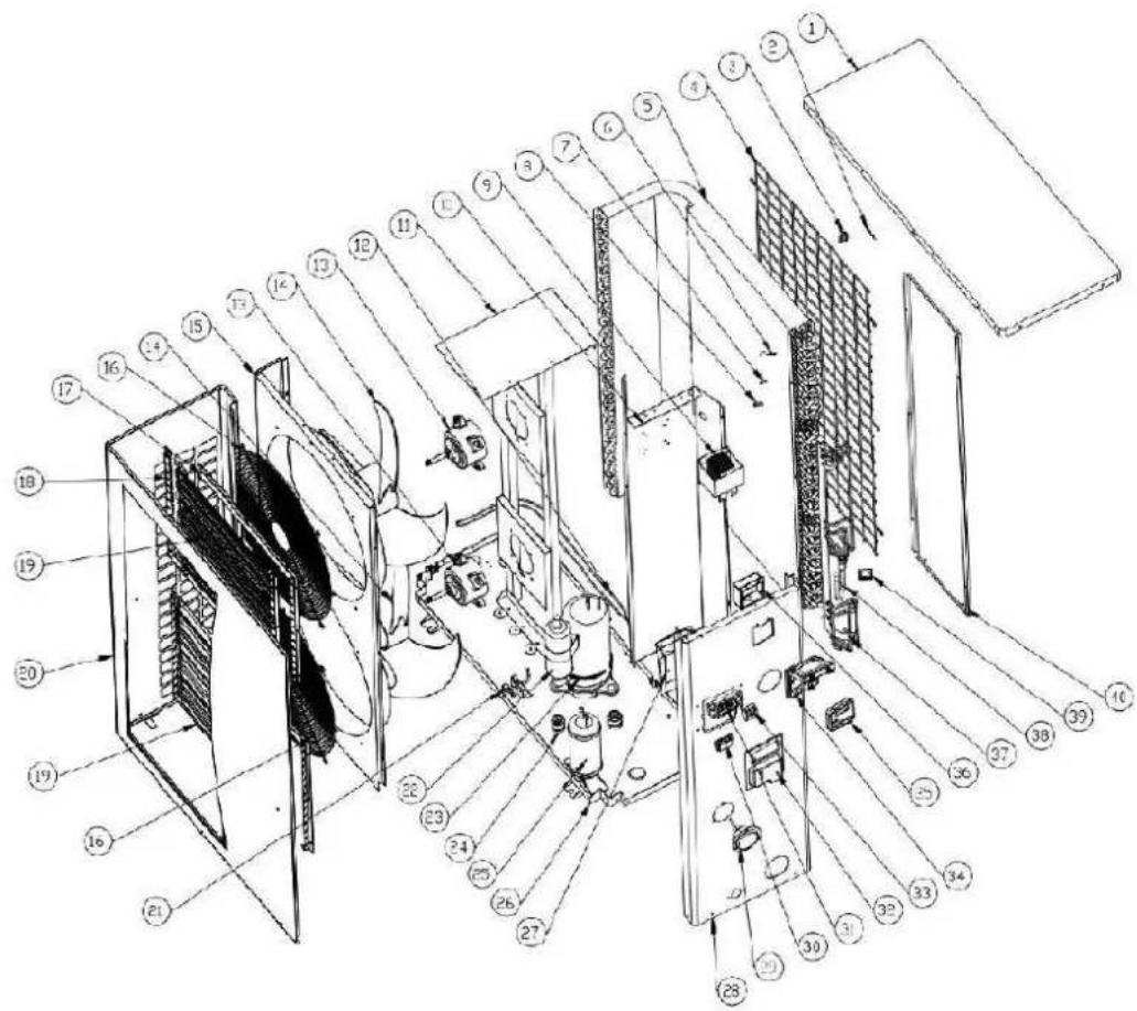
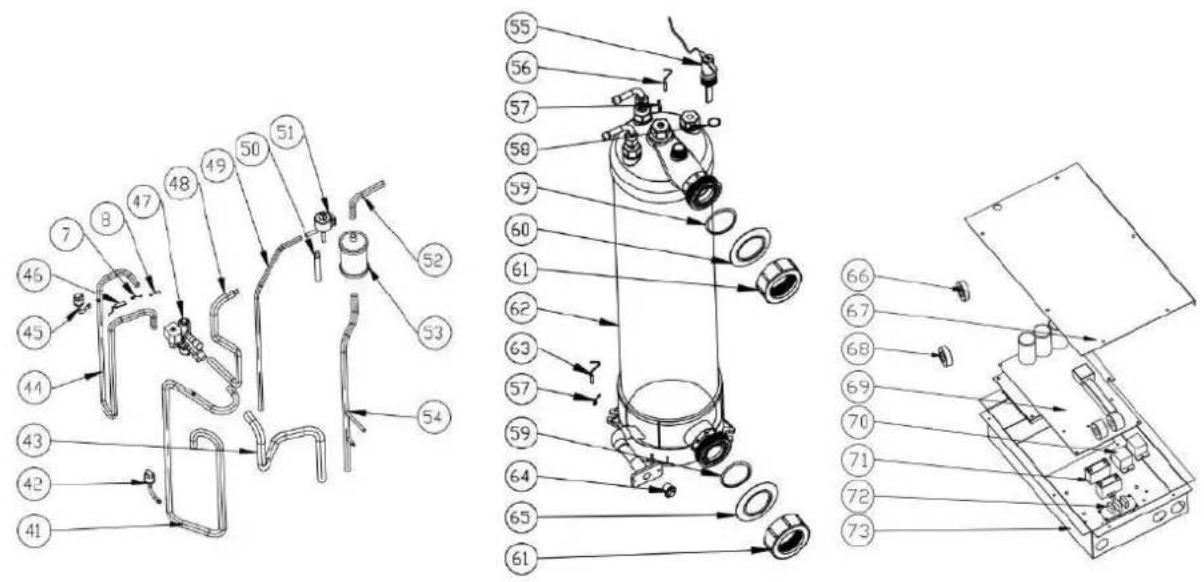
9. Exploded Diagram and spares parts list
9.1 Model :BEXP05i/BEXP07i/BEXP09i
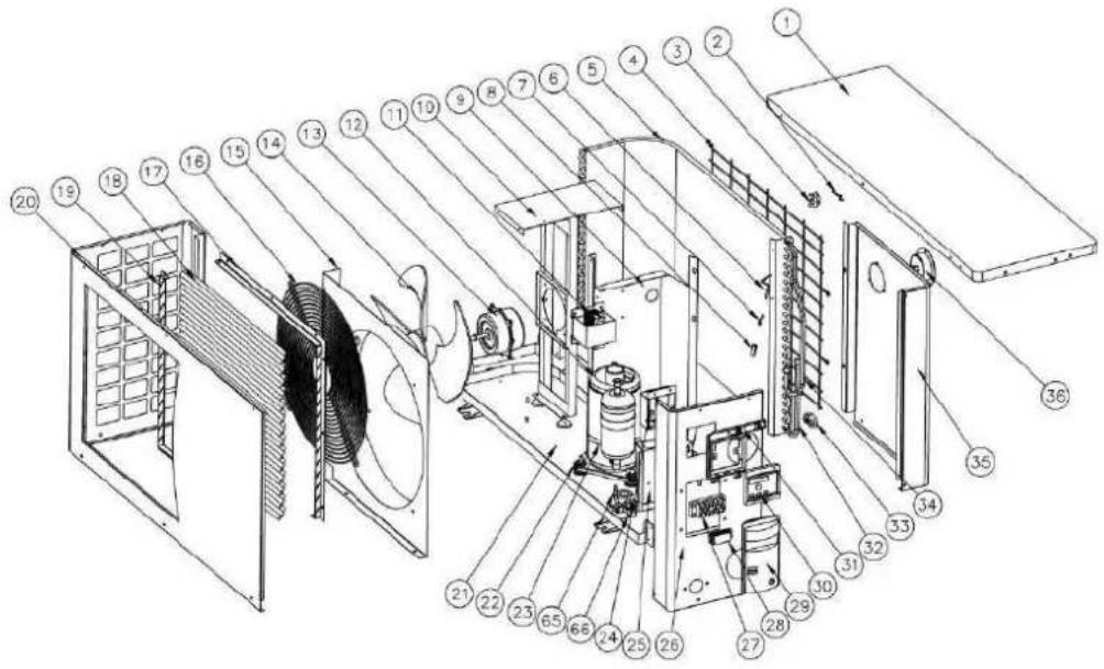


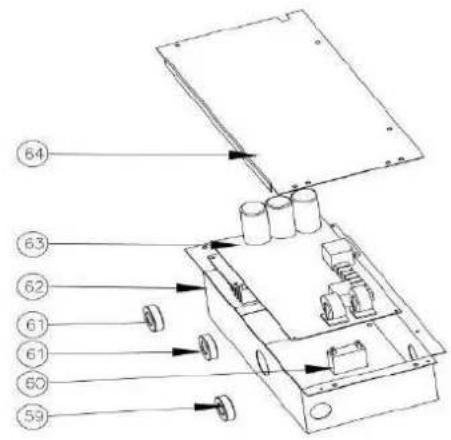
| NO | ERP | Parts name | NO | ERP | Parts name |
| 1 | 108030156 | Top cover | 34 | 103000218 | Distributor assembly |
| 2 | 117110020 | Ambient temp. sensor T5-TH1 | 35 | 108030168 | Back panel |
| 3 | 133020010 | Ambient temp. sensor clip | 36 | 106000011 | Pressure gauge |
| 4 | 108030167 | Back grill | 37 | 113090059 | Exchanger to capillaries |
| 5 | 103000218 | Evaporator | 38 | 113100010 | Coupling pipe |
| 6 | 117110004 | Evaporator temperature sensor T3-TH2 | 39 | 109000096 | Capillary |
| 7 | 113190001 | Sensor holder | 40 | 113020320 | Gas return piping |
| 8 | 113190001 | Temperature sensor casing pipe | 41 | 112100046 | Low pressure switch |
| 9 | 108030170 | Isolation panel | 42 | 113010229 | Discharge piping |
| 10 | 108030169 | Fan motor bracket | 43 | 112100030 | High pressure switch |
| 11 | 117230003 | Reactor | 44 | 113060123 | 4-way valve to collective pipe |
| 12 | 101000187 | Compressor + damping feet | 45 | 117110021 | Discharge temp. sensor T6-TH3 |
| 13 | 112000069 | Fan motor | 46 | 113030132 | 4-way valve to exchanger |
| 14 | 113600007 | Fan blade | 47 | 121000001 | 4 way valve |
| 15 | 108030158 | Front Fan board | 48 | 102050004 | Water connection sets |
| 16 | 108030045 | Fan grill | 49 | 133020011 | Blue rubber ring |
| 17 | 108030163 | Grill board support 1 | 50 | 102050006 | Drainage plug |
| 18 | 108030160 | Front grill board | 51 | 133020006 | Rubber ring on water connection |
| 19 | 108030164 | Grill board support 2 | 52 | 108010025 | Exchanger temperature sensor clip |
| 20 | 108030161 | Front panel | 53 | 117110012 | Water inlet temp. sensor TH6 |
| 21 | 108030155 | Base tray | 54 | 133020012 | Red rubber ring |
| 22 | 101000187 | Compressor + damping feet | 55 | 102040757 | Titanium heat exchanger |
| 23 | 142000072 | Compressor heatingresistor | 56 | 136020083 | Sealing ring |
| 24 | 133030011 | Wiring box | 57 | 112100021-1 | Water flow switch |
| 25 | 108010030 | Terminal Board | 58 | 117110011 | Water outlet temp. sensor T2-TH5 |
| 26 | 108030157 | Right side panel | 59 | 117240003 | Magnet ring |
| 27 | 115000004 | 5-ways terminal block | 60 | 111000002 | Fan capacitance |
| 28 | 136010004 | Clip | 61 | 117240002 | Magnet ring |
| 29 | 133020020 | Handle | 62 | 108030095 | Electric box |
| 30 | 117020150 | Controller | 63 | 117100046 | PCB |
| 31 | 113712007 | Waterproof controller box | 64 | 108030059 | Electric box cover |
| 32 | 103000218 | Evaporator pipe | 65 | 113100008 | Coupling pipe |
| 33 | 136020018 | B Type Rubber fixing block | 66 | 120000091 | Globe valve |
Spare parts list model: BEXP07i
| NO | ERP | Parts name | NO | ERP | Parts name |
| 1 | 108030156 | Top cover | 34 | 103000218 | Distributor assembly |
| 2 | 117110020 | Ambient temp. sensor T5-TH1 | 35 | 108030168 | Back panel |
| 3 | 133020010 | Ambient temp. sensor clip | 36 | 106000011 | Pressure gauge |
| 4 | 108030039 | Back grill | 37 | 113090059 | Exchanger to capillaries |
| 5 | 103000218 | Evaporator | 38 | 113100010 | Coupling pipe |
| 6 | 117110004 | Evaporator temperature sensor T3-TH2 | 39 | 109000095 | Capillary |
| 7 | 113190001 | Sensor holder | 40 | 113020320 | Gas return piping |
| 8 | 113190001 | Temperature sensor casing pipe | 41 | 116000069 | Low pressure switch |
| 9 | 108030170 | Isolation panel | 42 | 113010229 | Discharge piping |
| 10 | 108030169 | Fan motor bracket | 43 | 116000066 | High pressure switch |
| 11 | 117230003 | Reactor | 44 | 113060123 | 4-way valve to collective pipe |
| 12 | 101000187 | Compressor + damping feet | 45 | 117110021 | Discharge temp. sensor T6-TH3 |
| 13 | 112000069 | Fan motor | 46 | 113030091 | 4-way valve to exchanger |
| 14 | 113600007 | Fan blade | 47 | 121000001 | 4 way valve |
| 15 | 108030158 | Front Fan board | 48 | 113900082 | Water connection sets |
| 16 | 108030045 | Fan grill | 49 | 133020011 | Blue rubber ring |
| 17 | 108030163 | Grill board support 1 | 50 | 150000110 | Drainage plug |
| 18 | 108030160 | Front grill board | 51 | 133020026 | Rubber ring on water connection |
| 19 | 108030164 | Grill board support 2 | 52 | 108010025 | Exchanger temperature sensor clip |
| 20 | 108030161 | Front panel | 53 | 117110012 | Water inlet temp. sensor T1-TH6 |
| 21 | 108030155 | Base tray | 54 | 133020012 | Red rubber ring |
| 22 | 101000187 | Compressor + damping feet | 55 | 102040758 | Titanium heat exchanger |
| 23 | 142000072 | Compressor heatingresistor | 56 | 136020083 | Sealing ring |
| 24 | 133030011 | Wiring box | 57 | 112100021-1 | Water flow switch |
| 25 | 108010030 | Terminal Board | 58 | 117110011 | Water outlet temp. sensor T2-TH5 |
| 26 | 108030157 | Right side panel | 59 | 117240003 | Magnet ring |
| 27 | 115000004 | 5-ways terminal block | 60 | 111300002 | Fan capacitance |
| 28 | 136010004 | Clip | 61 | 117240002 | Magnet ring |
| 29 | 133020020 | Handle | 62 | 108030095 | Electric box |
| 30 | 117020150 | Controller | 63 | 117100046 | PCB |
| 31 | 108010021 | Waterproof controller box | 64 | 108030059 | Electric box cover |
| 32 | 103000218 | Evaporator pipe | 65 | 113100008 | Coupling pipe |
| 33 | 136020018 | B Type Rubber fixing block | 66 | 120000091 | Globe valve |
Spare parts list model: BEXP09i
| NO | ERP | Parts name | NO | ERP | Parts name |
| 1 | 108030156 | Top cover | 34 | 103000218 | Distributor assembly |
| 2 | 117110020 | Ambient temp. sensor T5-TH1 | 35 | 108030168 | Back panel |
| 3 | 133020010 | Ambient temp. sensor clip | 36 | 106000011 | Pressure gauge |
| 4 | 108030039 | Back grill | 37 | 113090059 | Exchanger to capillaries |
| 5 | 103000218 | Evaporator | 38 | 113100010 | Coupling pipe |
| 6 | 117110004 | Evaporator temperature sensor T3-TH2 | 39 | 109000098 | Capillary |
| 7 | 113190001 | Temperature sensor piping clip | 40 | 113020320 | Gas return piping |
| 8 | 113190001 | Temperature sensor casing pipe | 41 | 116000069 | Low pressure switch |
| 9 | 108030170 | Isolation panel | 42 | 113010229 | Discharge piping |
| 10 | 108030169 | Fan motor bracket | 43 | 116000066 | High pressure switch |
| 11 | 117230003 | Reactor | 44 | 113060123 | 4-way valve to collective pipe |
| 12 | 101000187 | Compressor + damping feet | 45 | 117110021 | Discharge temp. sensor T6-TH3 |
| 13 | 112000069 | Fan motor | 46 | 113030091 | 4-way valve to exchanger |
| 14 | 113600007 | Fan blade | 47 | 121000001 | 4 way valve |
| 15 | 108030158 | Front Fan board | 48 | 113900082 | Water connection sets |
| 16 | 108030045 | Fan grill | 49 | 133020011 | Blue rubber ring |
| 17 | 108030163 | Grill board support 1 | 50 | 150000110 | Drainage plug |
| 18 | 108030160 | Front grill board | 51 | 133020026 | Rubber ring on water connection |
| 19 | 108030164 | Grill board support 2 | 52 | 108010025 | Exchanger temperature sensor clip |
| 20 | 108030161 | Front panel | 53 | 117110012 | Water inlet temp. sensor T1-TH6 |
| 21 | 108030155 | Base tray | 54 | 133020012 | Red rubber ring |
| 22 | 101000187 | Compressor + damping feet | 55 | 102040759 | Titanium heat exchanger |
| 23 | 142000072 | Compressor heating resistor | 56 | 136020083 | Sealing ring |
| 24 | 133030011 | Wiring box | 57 | 112100021-1 | Water flow switch |
| 25 | 108010030 | Terminal Board | 58 | 117110011 | Water outlet temp. sensor T2-TH |
| 26 | 108030157 | Right side panel | 59 | 117240003 | Magnet ring |
| 27 | 115000004 | 5-ways terminal block | 60 | 111300002 | Fan capacitance |
| 28 | 136010004 | Clip | 61 | 117240002 | Magnet ring |
| 29 | 133020020 | Handle | 62 | 108030095 | Electric box |
| 30 | 117020150 | Controller | 63 | 117100046 | PCB |
| 31 | 108010021 | Waterproof controller box | 64 | 108030059 | Electric box cover |
| 32 | 103000218 | Evaporator pipe | 65 | 113100008 | Coupling pipe |
| 33 | 136020018 | B Type Rubber fixing block | 66 | 120000091 | Globe valve |
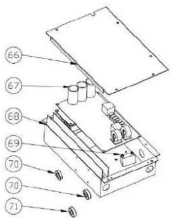
9.2 Model: BEXP11i


Spare parts list model: BEXP11i
| NO | ERP | Parts name | NO | ERP | Parts name |
| 1 | 108050103 | Top cover | 34 | 103000221 | Distributor assembly |
| 2 | 117110020 | Ambient temp. sensor T5-TH | 35 | 108050114 | Back panel |
| 3 | 133020010 | Ambient temp. sensor clip | 36 | 113190001 | Temperature sensor piping clip |
| 4 | 108050104 | Back grill | 37 | 113190001 | Temperature sensor casing pipe |
| 5 | 103000221 | Evaporator | 38 | 117110004 | Evaporator temperature sensor T3-TH2 |
| 6 | 108050105 | Isolation panel | 39 | 113020322 | Gas return piping |
| 7 | 108050106 | Fan motor bracket | 40 | 113010210 | Discharge piping |
| 8 | 117230003 | Reactor | 41 | 116000066 | High pressure switch |
| 9 | 112000070 | Fan motor | 42 | 116000069 | Low pressure switch |
| 10 | 132000013 | Fan blade | 43 | 117110021 | Discharge temp. sensor T6-TH3 |
| 11 | 108050107 | Front Fan board | 44 | 113030086 | 4-way valve to exchanger |
| 12 | 108010014 | Fan grill | 45 | 121000006 | 4 way valve |
| 13 | 108050108 | Grill board support 1 | 46 | 113090058 | 4-way valve to capillary |
| 14 | 108050109 | Front grill board | 47 | 109000044 | Capillary |
| 15 | 108050110 | Grill board support 2 | 48 | 113060084 | 4-way valve to collective pipe |
| 16 | 108050111 | Front panel | 49 | 112100021-1 | Water flow switch |
| 17 | 113100008 | Globe valve support | 50 | 136020083 | Sealing ring |
| 18 | 142000074 | Compressor heating resistor | 51 | 117110011 | Water outlet temp. sensor T2-TH |
| 19 | 120000091 | Global valve | 52 | 108010025 | Exchanger temperature sensor cli |
| 20 | 101000188 | Compressor + damping feet | 53 | 102040760 | Titanium heat exchanger |
| 21 | 101000188 | Compressor + damping feet | 54 | 133020026 | Rubber ring on water connection |
| 22 | 108050112 | Base tray | 55 | 133020012 | Red rubber ring |
| 23 | 108010016 | Terminal Board | 56 | 113900082 | Water connection sets |
| 24 | 108050113 | Right side panel | 57 | 117110012 | Water inlet temp. sensor T1-TH6 |
| 25 | 106000011 | Pressure gauge | 58 | 150000110 | Drainage plug |
| 26 | 136010004 | Clip | 59 | 133020011 | Blue rubber ring |
| 27 | 133020029 | Handle | 60 | 108050017 | Electric box cover |
| 28 | 115000004 | 5-ways terminal block | 61 | 117100046 | PCB |
| 29 | 117020150 | Controller | 62 | 108110031 | Electric box |
| 30 | 133030011 | Wiring box | 63 | 111000006 | Fan capacitance |
| 31 | 108010021 | Waterproof controller box | 64 | 117240002 | Magnet ring |
| 32 | 103000221 | Evaporator pipe | 65 | 117240003 | Magnet ring |
| 33 | 136020018 | B Type Rubber fixing block |
9.3 Model: BEXP14i/BEXP16i
Spare parts list model: BEXP14i
| NO | ERP | Parts name | NO | ERP | Parts name |
| 1 | 108050103 | Top cover | 35 | 103000182 | Distributor assembly |
| 2 | 117110020 | Ambient temp. sensor T5-TH1 | 36 | 108050114 | Back panel |
| 3 | 133020010 | Ambient temp. sensor clip | 37 | 113190001 | Temperature sensor piping clip |
| 4 | 108050104 | Back grill | 38 | 113190001 | Temperature sensor casing pipe |
| 5 | 103000182 | Evaporator | 39 | 117110004 | Evaporator temperature sensor T3-TH2 |
| 6 | 108050105 | Isolation panel | 40 | 113020322 | Gas return piping |
| 7 | 108050106 | Fan motor bracket | 41 | 113010210 | Discharge piping |
| 8 | 117230003 | Reactor | 42 | 116000066 | High pressure switch |
| 9 | 112000070 | Fan motor | 43 | 116000069 | Low pressure switch |
| 10 | 132000013 | Fan blade | 44 | 117110021 | Discharge temp. sensor T6-TH3 |
| 11 | 108050107 | Front Fan board | 45 | 113030086 | 4-way valve to exchanger |
| 12 | 108010014 | Fan grill | 46 | 121000006 | 4 way valve |
| 13 | 108050108 | Grill board support 1 | 47 | 119000017 | EEV |
| 14 | 108050109 | Front grill board | 48 | 113080054 | EEV to distribution tube |
| 15 | 108050110 | Grill board support 2 | 49 | 113070044 | TT exchanger to EEV tube |
| 16 | 108050111 | Front panel | 50 | 113060084 | 4-way valve to collective pipe |
| 17 | 113100008 | Globe valve support | 51 | 112100021-1 | Water flow switch |
| 18 | 142000074 | Compressor heating resistor | 52 | 136020083 | Sealing ring |
| 19 | 120000091 | Global valve | 53 | 117110011 | Water outlet temp. sensor T2-TH5 |
| 20 | 101000188 | Compressor + damping feet | 54 | 108010025 | Exchanger temperature sensor |
| 21 | 101000188 | Compressor + damping feet | 55 | 102040761 | Titanium heat exchanger |
| 22 | 108050112 | Base tray | 56 | 133020026 | Rubber ring on water connection |
| 23 | 108010016 | Terminal Board | 57 | 133020012 | Red rubber ring |
| 24 | 108050113 | Right side panel | 58 | 113900082 | Water connection sets |
| 25 | 106000011 | Pressure gauge | 59 | 117110012 | Water inlet temp. sensor T1-TH6 |
| 26 | 136010004 | Clip | 60 | 150000110 | Drainage plug |
| 27 | 133020029 | Handle | 61 | 133020011 | Blue rubber ring |
| 28 | 115000004 | 5-ways terminal block | 62 | 108050017 | Electric box cover |
| 29 | 117020150 | Controller | 63 | 117100047 | PCB |
| 30 | 133030011 | Wiring box | 64 | 108110045 | Electric box |
| 31 | 108010021 | Waterproof controller box | 65 | 111000006 | Fan capacitance |
| 32 | 142000142 | Evaporator heating resistor (Optional) | 66 | 117240002 | Magnet ring |
| 33 | 103000182 | Evaporator pipe | 67 | 117240003 | Magnet ring |
| 34 | 136020018 | B Type Rubber fixing block |
Spare parts list model: BEXP16i
| NO | ERP | Parts name | NO | ERP | Parts name |
| 1 | 108050103 | Top cover | 35 | 103000220 | Distributor assembly |
| 2 | 117110020 | Ambient temp. sensor T5-TH1 | 36 | 108050114 | Back panel |
| 3 | 133020010 | Ambient temp. sensor clip | 37 | 113190001 | Temperature sensor piping clip |
| 4 | 108050104 | Back grill | 38 | 113190001 | Temperature sensor casing pipe |
| 5 | 103000220 | Evaporator | 39 | 117110004 | Evaporator temperature sensor T3-TH2 |
| 6 | 108050105 | Isolation panel | 40 | 113020321 | Gas return piping |
| 7 | 108050106 | Fan motor bracket | 41 | 113010159 | Dischargepiping |
| 8 | 117230003 | Reactor | 42 | 116000066 | High pressure switch |
| 9 | 112000070 | Fan motor | 43 | 116000069 | Low pressure switch |
| 10 | 132000013 | Fan blade | 44 | 117110021 | Dischargetemp. sensor T6-TH3 |
| 11 | 108050107 | Front Fan board | 45 | 113030081 | 4-way valve to exchanger |
| 12 | 108010014 | Fan grill | 46 | 121000006 | 4 way valve |
| 13 | 108050108 | Grill board support 1 | 47 | 119000017 | EEV |
| 14 | 108050109 | Front grill board | 48 | 113080054 | EEV to distribution tube |
| 15 | 108050110 | Grill board support 2 | 49 | 113070041 | TT exchanger to EEV tube |
| 16 | 108050111 | Front panel | 50 | 113060084 | 4-way valve to collective pipe |
| 17 | 113100008 | Globe valve support | 51 | 112100021-1 | Water flow switch |
| 18 | 142000074 | Compressor heating resistor | 52 | 136020083 | Sealing ring |
| 19 | 120000091 | Global valve | 53 | 117110011 | Water out temp. sensor T2-TH5 |
| 20 | 101000181 | Compressor + damping feet | 54 | 108010025 | Exchanger temperature sensor clip |
| 21 | 101000181 | Compressor + damping feet | 55 | 102040762 | Titanium heat exchanger |
| 22 | 108050115 | Base tray | 56 | 133020026 | Rubber ring on water connection |
| 23 | 108010016 | Terminal Board | 57 | 133020012 | Red rubber ring |
| 24 | 108050113 | Right side panel | 58 | 113900082 | Water connection sets |
| 25 | 106000011 | Pressure gauge | 59 | 117110012 | Water in temp. sensor T1-TH6 |
| 26 | 136010004 | Clip | 60 | 150000110 | Drainage plug |
| 27 | 133020029 | Handle | 61 | 133020011 | Blue rubber ring |
| 28 | 115000004 | 5-ways terminal block | 62 | 108050017 | Electric box cover |
| 29 | 117020150 | Controller | 63 | 117100047 | PCB |
| 30 | 133030011 | Wiring box | 64 | 108110045 | Electric box |
| 31 | 108010021 | Waterproof controller box | 65 | 111000006 | Fan capacitance |
| 32 | 142000142 | Evaporator heating resistor (Optional) | 66 | 117240002 | Magnet ring |
| 33 | 103000220 | Evaporator pipe | 67 | 117240003 | Magnet ring |
| 34 | 136020018 | B Type Rubber fixing block |

Spare parts list model: BEXP18i
| NO | ERP | Parts name | NO | ERP | Parts name |
| 1 | 108050103 | Top cover | 37 | 108050114 | Back panel |
| 2 | 117110020 | Ambient temp. sensor T5-TH1 | 38 | 113190001 | Temperature sensor casing pipe |
| 3 | 133020010 | Ambient temp. sensor clip | 39 | 113190001 | Temperature sensor piping clip |
| 4 | 108050104 | Back grill | 40 | 117110004 | Evaporator temperature sensor T3-TH2 |
| 5 | 103000220 | Evaporator | 41 | 113130021 | Filter to Liquid storage tank |
| 6 | 108050105 | Isolation panel | 42 | 113020321 | Gas return piping |
| 7 | 108050106 | Fan motor bracket | 43 | 120000066 | Filter |
| 8 | 117230003 | Reactor | 44 | 112100030 | High pressure switch |
| 9 | 112000070 | Fan motor | 45 | 112100046 | Low pressure switch |
| 10 | 132000013 | Fan blade | 46 | 113010159 | Exhaust piping |
| 11 | 108050107 | Front grill board | 47 | 117110021 | Discharge temp. sensor T6-TH3 |
| 12 | 108010014 | Fan grill | 48 | 113030081 | 4-way valve to exchanger |
| 13 | 108050108 | Grill board support 1 | 49 | 121000006 | 4 way valve |
| 14 | 108050109 | Grill board support | 50 | 113060084 | 4-way valve to collect pipe |
| 15 | 108050110 | Grill board support 2 | 51 | 113080078 | Liquid storage tank to EEV |
| 16 | 108050111 | Front grill board | 52 | 113170021 | Exchanger to filter |
| 17 | 113100008 | Globe valve support | 53 | 119000043 | EEV |
| 18 | 142000074 | Compressor heating resistor | 54 | 113120025 | EEV to distribution piping |
| 19 | 120000091 | Globe valve | 55 | 112100021-1 | Water flow switch |
| 20 | 101000189 | Compressor + damping feet | 56 | 136020083 | Rubber fixing block |
| 21 | 101000189 | Compressor + damping feet | 57 | 117110057 | Water outlet temperature sensor T2-TH5 |
| 22 | 105000004 | Liquid storage tank | 58 | 108010025 | Exchanger temperature sensor clip |
| 23 | 108050116 | Base tray | 59 | 102040762 | Titanium heat exchanger |
| 24 | 108010016 | Terminal Board | 60 | 133020006 | Sealing ring |
| 25 | 108050113 | Right side panel | 61 | 133020012 | Red rubber ring |
| 26 | 106000011 | Pressure gauge | 62 | 102050004 | Water connection sets |
| 27 | 136010004 | Clip | 63 | 117110012 | Water inlet temperature sensor T1-TH6 |
| 28 | 133020029 | Handle | 64 | 102050006 | Drainage plug |
| 29 | 115000004 | 5-ways terminal block | 65 | 133020011 | Blue rubber ring |
| 30 | 117020150 | Controller | 66 | 108050017 | Electric box cover |
| 31 | 133030011 | Controller box | 67 | 117100047 | PCB |
| 32 | 113712007 | Waterproof controller box | 68 | 108110045 | Electric control box |
| 33 | 142000142 | Evaporator heating belt (Optional) | 69 | 111000006 | Fan capacitance |
| 34 | 103000220 | Collective assembly | 70 | 117240002 | Magnet ring |
| 35 | 136020018 | B-type rubber fixing block | 71 | 117240003 | Magnet ring |
| 36 | 103000220 | Distributor assembly |


Spare parts list model: BEXP20i
| NO | ERP | Parts name | NO | ERP | Parts name |
| 1 | 108540043 | Top cover | 37 | 103000230 | Distributor assembly |
| 2 | 117110020 | Ambient temp. sensor T5-TH1 | 38 | 136020005 | B Type Rubber fixing block |
| 3 | 133020010 | Ambient temp. sensor clip | 39 | 103000230 | Evaporator pipe |
| 4 | 108540044 | Back grill | 40 | 108540054 | Back panel |
| 5 | 103000230 | Evaporator | 41 | 116000069 | Low pressure switch |
| 6 | 113190001 | Temperature sensor casing | 42 | 113130021 | Filter to Liquid storage pot pipe |
| 7 | 113190001 | Temperature sensor piping cl | 43 | 113020325 | Gas return piping |
| 8 | 117110004 | Evaporator temperature sensor T3-TH2 | 44 | 116000066 | High pressure switch |
| 9 | 117230002 | Reactor | 45 | 113060122 | 4-way valve to collective pipe |
| 10 | 108540045 | Isolation panel | 46 | 117110021 | Discharge temp. sensor T6-TH3 |
| 11 | 108540046 | Fan motor bracket | 47 | 113010230 | Discharge piping |
| 12 | 101000189 | Compressor + damping feet | 48 | 121000006 | 4 way valve |
| 13 | 111400043 | Fan motor | 49 | 120000066 | Filter |
| 14 | 113600013 | Fan blade | 50 | 113170032 | dehydrator filter pipe |
| 15 | 108540047 | Front Fan board | 51 | 113120026 | Pipe to evaporator |
| 16 | 108010064 | Fan grill | 52 | 113030108 | 4-way valve to exchanger |
| 17 | 108540048 | Grill board support 1 | 53 | 119000043 | EEV |
| 18 | 108540049 | Front grill board | 54 | 113080079 | EEV to distribution tube |
| 19 | 108540050 | Grill board support 2 | 55 | 112100021-1 | Water flow switch |
| 20 | 108540051 | Front panel | 56 | 136020083 | Sealing ring |
| 21 | 108540052 | Base tray | 57 | 117110011 | Water outlet temp. sensor T2-TH5 |
| 22 | 101000189 | Compressor + damping feet | 58 | 108010025 | Exchanger temperature sensor clip |
| 23 | 142000074 | Compressor heating resistor | 59 | 102040763 | Titanium heating exchanger |
| 24 | 105000004 | Liquid storage pot | 60 | 133020026 | Rubber ring on water connection |
| 25 | 120000091 | Global valve | 61 | 133020012 | Red rubber ring |
| 26 | 108560034 | Global valve board | 62 | 113900082 | Water connection sets |
| 27 | 133030011 | Wiring box | 63 | 117110012 | Water inlet temp. sensor T1-TH6 |
| 28 | 108010016 | Terminal Board | 64 | 133020011 | Blue rubber ring |
| 29 | 108540053 | Right side panel | 65 | 150000110 | Drainage plug |
| 30 | 106000011 | Pressure gauge | 66 | 108540006 | Electric box cover |
| 31 | 136010004 | Clip | 67 | 117100048 | PCB |
| 32 | 133020029 | Handle | 68 | 108560012 | Electric box |
| 33 | 115000004 | 5-ways terminal block | 69 | 117240002 | Magnet ring |
| 34 | 117020150 | Controller | 70 | 117240003 | Magnet ring |
| 35 | 108010021 | Waterproof controller box | 71 | 111000006 | Fan capacitance |
| 36 | 142000144 | Evaporator heating resistor (Optional) |
Spare parts list model: BEXP25i
| NO | ERP | Parts name | NO | ERP | Parts name |
| 1 | 108470071 | Top cover | 38 | 103000233 | Distributor assembly |
| 2 | 117110020 | Ambient temp. sensor T5-TH1 | 39 | 136020005 | Rubber fixing block |
| 3 | 133020010 | Ambient temp. sensor clip | 40 | 108470082 | Back panel |
| 4 | 108470072 | Back grill | 41 | 113020326 | Gas return piping |
| 5 | 103000233 | Evaporator | 42 | 112100046 | Low pressure switch |
| 6 | 117110004 | Evaporator temperature sensor T3-TH | 43 | 113060083 | 4-way valve to collective pipe |
| 7 | 113190001 | Temperature sensor piping clip | 44 | 113010227 | Exhaust piping |
| 8 | 113190001 | Temperature sensor casing pipe | 45 | 112100030 | High pressure switch |
| 9 | 117230002 | Reactor | 46 | 117110021 | Discharge temp. sensor T6-TH3 |
| 10 | 1084700833 | Isolation panel | 47 | 121000009 | 4 way valve |
| 11 | 108470074 | Fan motor bracket | 48 | 113030087 | 4-way valve to exchanger |
| 12 | 142000079 | Evaporator heating belt (Optional) | 49 | 113120020 | Liquid storage tank to EEV |
| 13 | 112000070 | Fan motor | 50 | 113080055 | EEV to distribution piping |
| 14 | 132000013 | Fan blade | 51 | 119000021 | EEV |
| 15 | 108470075 | Front grill board | 52 | 113170028 | Exchanger to filter |
| 16 | 108010014 | Fan grill | 53 | 120000066 | Filter |
| 17 | 108470076 | Grill board support 1 | 54 | 113130020 | Filter to Liquid storage tank |
| 18 | 108470077 | Grill board support 2 | 55 | 112100021-1 | Water flow switch |
| 19 | 108470078 | Grill board support | 56 | 117110057 | Water outlet temperature sensor T2-TH5 |
| 20 | 108470079 | Front grill board | 57 | 108010025 | Exchanger temperature sensor clip |
| 21 | 120000091 | Globe valve | 58 | 136020083 | Sealing ring |
| 22 | 101000185 | Compressor + damping feet | 59 | 133020006 | Rubber ring on water connection |
| 23 | 142000077 | Compressor heating resistor | 60 | 133020012 | Red rubber ring |
| 24 | 101000185 | Compressor + damping feet | 61 | 102050004 | Water connection sets |
| 25 | 105000008 | Liquid storage tank | 62 | 102040776 | Titanium heat exchanger |
| 26 | 108470080 | Base tray | 63 | 117110012 | Water inlet temperature sensor T1-TH6 |
| 27 | 108010016 | Terminal Board | 64 | 102050006 | Drainage plug |
| 28 | 108470081 | Right side panel | 65 | 133020011 | Blue rubber ring |
| 29 | 106000011 | Pressure gauge | 66 | 117240002 | Magnet ring |
| 30 | 136010004 | Clip | 67 | 108550004 | Electric control box cover |
| 31 | 115000025 | Power supply 3-bit terminal | 68 | 117240003 | Magnet ring |
| 32 | 133020029 | Handle | 69 | 117100048 | PCB |
| 33 | 115000023 | 3-bit terminal | 70 | 142000038 | Relay |
| 34 | 113712007 | Waterproof controller box | 71 | 111000006 | Fan capacitance |
| 35 | 117020150 | Controller | 72 | N/A | N/A |
| 36 | 133030011 | Controller box | 73 | 108550003 | Electric control box |
| 37 | 103000233 | Collective assembly |
9.7 Model: BEXP30i


Spare parts list model: BEXP30i
| NO | ERP | Parts name | NO | ERP | Parts name |
| 1 | 108470071 | Top cover | 39 | 136020005 | Rubber fixing block |
| 2 | 117110020 | Ambient temp. sensor T5-TH1 | 40 | 108470082 | Back panel |
| 3 | 133020010 | Ambient temp. sensor clip | 41 | 113020326 | Gas return piping |
| 4 | 108470072 | Back grill | 42 | 112100046 | Low pressure switch |
| 5 | 103000208 | Evaporator | 43 | 113060083 | 4-way valve to collective pipe |
| 6 | 117110004 | Evaporator temperature sensor T3-TH2 | 44 | 113010227 | Exhaust piping |
| 7 | 113190001 | Temperature sensor piping clip | 45 | 112100030 | High pressure switch |
| 8 | 113190001 | Temperature sensor casing pipe | 46 | 117110021 | Discharge temp. sensor T6-TH3 |
| 9 | 117230004 | Reactor | 47 | 121000009 | 4 way valve |
| 10 | 108470073 | Isolation panel | 48 | 113030087 | 4-way valve to exchanger |
| 11 | 108470074 | Fan motor bracket | 49 | 113120020 | Liquid storage tank to EEV |
| 12 | 142000079 | Evaporator heating belt (Optional) | 50 | 113080055 | EEV to distribution piping |
| 13 | 112000070 | Fan motor | 51 | 119000022 | EEV |
| 14 | 132000013 | Fan blade | 52 | 113170028 | Exchanger to filter |
| 15 | 108470075 | Front grill board | 53 | 120000066 | Filter |
| 16 | 108010014 | Fan grill | 54 | 113130020 | Filter to Liquid storage tank |
| 17 | 108470076 | Grill board support 1 | 55 | 112100021 | Water flow switch |
| 18 | 108470077 | Grill board support 2 | 56 | 117110011 | Water outlet temperature sensor T2-TH |
| 19 | 108470078 | Grill board support | 57 | 108010025 | Exchanger temperature sensor clip |
| 20 | 108470079 | Front grill board | 58 | 136020083 | Sealing ring |
| 21 | 120000091 | Globe valve | 59 | 133020006 | Rubber ring on water connection |
| 22 | 101000185 | Compressor + damping feet | 60 | 133020012 | Red rubber ring |
| 23 | 142000077 | Compressor heating resistor | 61 | 102050004 | Water connection sets |
| 24 | 101000185 | Compressor + damping feet | 62 | 102040776 | Titanium heat exchanger |
| 25 | 105000008 | Liquid storage tank | 63 | 117110012 | Water inlet temperature sensor T1-TH6 |
| 26 | 108470080 | Base tray | 64 | 102050006 | Drainage plug |
| 27 | 108010016 | Terminal Board | 65 | 133020011 | Blue rubber ring |
| 28 | 108470081 | Right side panel | 66 | 108470006 | Electric control box cover |
| 29 | 106000011 | Pressure gauge | 67 | 117140016 | Driver board |
| 30 | 136010004 | Clip | 68 | 117240002 | Magnet ring |
| 31 | 115000025 | Power supply 3-bit terminal | 69 | 111000006 | Fan capacitance |
| 32 | 133020029 | Handle | 70 | 117260001 | Filter board |
| 33 | 115000023 | 3-bit terminal | 71 | 117250007 | Main board |
| 34 | 113712007 | Waterproof controller box | 72 | 108470028 | Scale board |
| 35 | 117020150 | Controller | 73 | 108470027 | Electric control box |
| 36 | 133030011 | Controller box | 74 | 142000038 | Relay |
| 37 | 103000208 | Collective assembly | 75 | 117240003 | Magnet ring |
| 38 | 103000208 | Distributor assembly |
10. Maintenance
(1) You should check the water supply system regularly to avoid the air entering the system and occurrence of low water flow, because it would reduce the performance and reliability of HP unit.
(2) Clean your pools and filtration system regularly to avoid the damage of the unit.
(3) Only a qualified technician is authorized to operate the cooling system pressure.
(4) In another way, you should check the unit is water fully before the unit starts to run again.
(5) Check the water levels before the unit starts after a long break in usage.
(6) When the unit is running, there is all the time a little water discharge under the unit. This is normal.
(7) Please fill the R32 gas from the globe valve inside machine.
BEXP05i/BEXP07i/BEXP09i


BEXP20i


BEXP25i/BEXP30i
2. Condition de transport

Patin caoutchouc anti-vibration, qt4
Ref: BEXP05i/BEXP07i/BEXP09i/BEXP11i/BEXP14i/BEXP16i/BEXP18i/BEXP20i
Ref: BEXP25i
Tset-1 = 28-1 = 27°C
Tset +1 = plus de 1^ de la tempereature de consigne
Tset+1=28+1=29°C
7.8 Protection de la machine
Remarques :
BEXP05i/BEXP07i/BEXP09i


BEXP20i


BEXP25i/BEXP30i


2. Transport en opslag
2.1 Transport

CE-norm, R32, ABS-kast
| Model | BEXP05i | BEXP07i | BEXP09i | BEXP11i | BEXP14i | |
| * Prestaties bij Air 28 °C, het water 28 °C, luchtvochtigheid 80% | ||||||
| Verwarmingscapacitei | kW | 5-3.2 | 7-3.3 | 9-3.5 | 11-4.8 | 14-5 |
| Energieverbruik | kW | 0.98-0.43 | 1.32-0.43 | 1.61-0.43 | 1.96-0.6 | 2.5-0.63 |
| C.O.P. | 7.4-5.1 | 7.7-5.3 | 8.5-5.6 | 8.5-5.6 | 8.5-5.6 | |
| * Prestaties bij Air 15 °C, het water 26 °C, luchtvochtigheid 70% | ||||||
| Verwarmingscapacitei | kW | 3.7-2.3 | 4.7-2.4 | 6.6-2.5 | 7.9-3.5 | 9.5-3.6 |
| Energieverbruik | kW | 0.93-0.43 | 1.18-0.43 | 1.65-0.43 | 1.98-0.6 | 2.38-0.62 |
| C.O.P. | 5.4-4 | 5.6-4 | 5.8-4 | 5.8-4 | 5.8-4 | |
| * Prestaties bij Air 0°C, het water 26 °C, luchtvochtigheid 78% | ||||||
| Verwarmingscapacitei | kW | 2.76-1.7 | 3.5-2.0 | 4.50-2.3 | 5.5-3.0 | 7-3.2 |
| Energieverbruik | kW | 0.99-0.40 | 1.25-0.48 | 1.61-0.55 | 1.96-0.71 | 2.5-0.76 |
| C.O.P. | 4.2-2.8 | 4.2-2.8 | 4.2-2.8 | 4.2-2.8 | 4.2-2.8 | |
| Compressor | MITSUBISHI INVERTER COMPRESSOR | |||||
| Spanning | V | 220~240V / 50Hz or 60Hz /1PH | ||||
| Nominale stroom | A | 4.40 | 5.90 | 7.20 | 8.70 | 11.00 |
| Minimale zekering | A | 7.00 | 9.00 | 11.00 | 13.00 | 17.00 |
| Aanbevolen | m³ | 0-15 | 10-25 | 15-30 | 20-60 | 20-66 |
| Geadviseerde | m³/h | 2.50 | 2.50 | 2.80 | 3.70 | 4.00 |
| Waterdrukval | Kpa | 12 | 12 | 12 | 14 | 15 |
| Warmtewisselaar | Twist-titanium tube in PVC | |||||
| Wateraansluiting | mm | 50 | ||||
| Fan hoeveelheid | 1 | |||||
| Ventilator snelheid | RPM | 650-870 | 650-850 | |||
| Ingangsvermögen van | W | 80 | 200 | |||
| Geluidsniveau (10m) | dB(A) | 36-42 | 37-42 | 37-43 | 39-45 | 40-46 |
| Geluidsniveau (1m) | dB(A) | 44-51 | 45-52 | 45-52 | 46-54 | 47-56 |
| Koelmiddel (R32) | g | 400 | 500 | 650 | 750 | 950 |
| CO2 gelijkwaardig | Tonne | 0.27 | 0.34 | 0.44 | 0.51 | 0.64 |
| Netto gewicht | kg | 52.00 | 54.00 | 56.00 | 68.00 | 73.00 |
| Bruto gewicht | kg | 64.00 | 66.00 | 68.00 | 73.00 | 78.00 |
| Net dimensie | mm | 1049*375*551 | 1086*450*693 | |||
| Verpakking dimensie | mm | 1110*430*705 | 1140*495*855 | |||
| Model | BEXP16i | BEXP18i | BEXP20i | BEXP25i | BEXP30i | |
| * Prestaties bij Air 28 °C, het water 28 °C, luchtvochtigheid 80% | ||||||
| Verwarmingscapaciteit | kW | 16-5.3 | 17.5-5.3 | 19-4.7 | 24-5.9 | 28.5-6.8 |
| Energieverbruik | kW | 2.85-0.66 | 3.21-0.66 | 3.39-0.59 | 4.29-0.74 | 5.09-0.85 |
| C.O.P. | 8.5-5.6 | 8.5-5.6 | 8.5-5.6 | 8.5-5.6 | 8.5-5.6 | |
| * Prestaties bij Air 15 °C, het water 26 °C, luchtvochtigheid 70% | ||||||
| Verwarmingscapaciteit | kW | 11.2-3.8 | 12.5-3.8 | 14-3.9 | 17.2-4.7 | 22.8-5.6 |
| Energieverbruik | kW | 2.8-0.66 | 3.12-0.66 | 3.5-0.67 | 4.3-0.81 | 5.7-0.97 |
| C.O.P. | 5.8-4 | 5.8-4 | 5.8-4 | 5.8-4 | 5.8-4 | |
| * Prestaties bij Air 0°C, het water 26 °C, luchtvochtigheid 78% | ||||||
| Verwarmingscapaciteit | kW | 7.11-4.1 | 8.15-4.45 | 9.3-4.8 | 12-6.7 | 15.1-8.5 |
| Energieverbruik | kW | 2.54-0.95 | 2.91-1.03 | 3.32-1.09 | 4.29-1.53 | 5.34-1.95 |
| C.O.P. | 4.3-2.8 | 4.3-2.8 | 4.4-2.8 | 4.4-2.8 | 4.4-2.8 | |
| Compressor | MITSUBISHI INVERTER COMPRESSOR | |||||
| Spanning | V | 220~240V / 50Hz or 60Hz /1PH | ||||
| Nominate stroom | A | 11.90 | 14.30 | 15.00 | 19.00 | 22.60 |
| Minimale zekering | A | 18.00 | 22.00 | 23.00 | 29.00 | 34.00 |
| Aanbevolen poolvolume | m³ | 30-85 | 30-90 | 55-120 | 65-130 | 75-180 |
| Geadviseerde waterflux | m³/h | 4.60 | 5.00 | 5.00 | 8.00 | 10.00 |
| Waterdrukval | Kpa | 15 | 15 | 18 | 20 | 25 |
| Warmtewisselaar | Twist-titanium tube in PVC | |||||
| Wateraansluiting | mm | 50 | ||||
| Fan hoeveelheid | 1 | 2 | ||||
| Ventilator snelheid | RPM | 650-850 | 450-650 | (650-850)*2 | ||
| Ingangsvermögen van Fan | W | 200 | 150 | 200*2 | ||
| Geluidsniveau (10m) | dB(A) | 40-46 | 40-46 | 42-48 | 42-49 | 42-51 |
| Geluidsniveau (1m) | dB(A) | 47-56 | 47-56 | 49-58 | 49-59 | 50-60 |
| Koelmiddel (R32) | g | 1100 | 1300 | 1500 | 1800 | 2300 |
| CO2 gelijkwaardig | Tonne | 0.74 | 0.88 | 1.01 | 1.22 | 1.55 |
| Netto gewicht | kg | 78.00 | 80.00 | 98.00 | 117.00 | 128.00 |
| Bruto gewicht | kg | 83.00 | 85.00 | 113.00 | 135.00 | 146.00 |
| Net dimensie | mm | 1086*450*693 | 1118*455*860 | 1100*452*1280 | ||
| Verpakking dimensie | mm | 1140*495*855 | 1215*510*1015 | 1156*500*1425 | ||
4.Toebehoren lijst
4.1 Toebehoren
Ref: BEXP05i/BEXP07i/BEXP09i/BEXP11i/BEXP14i/BEXP16i/BEXP18i/BEXP20i
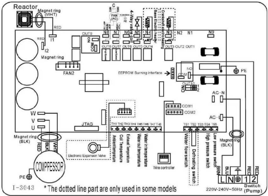
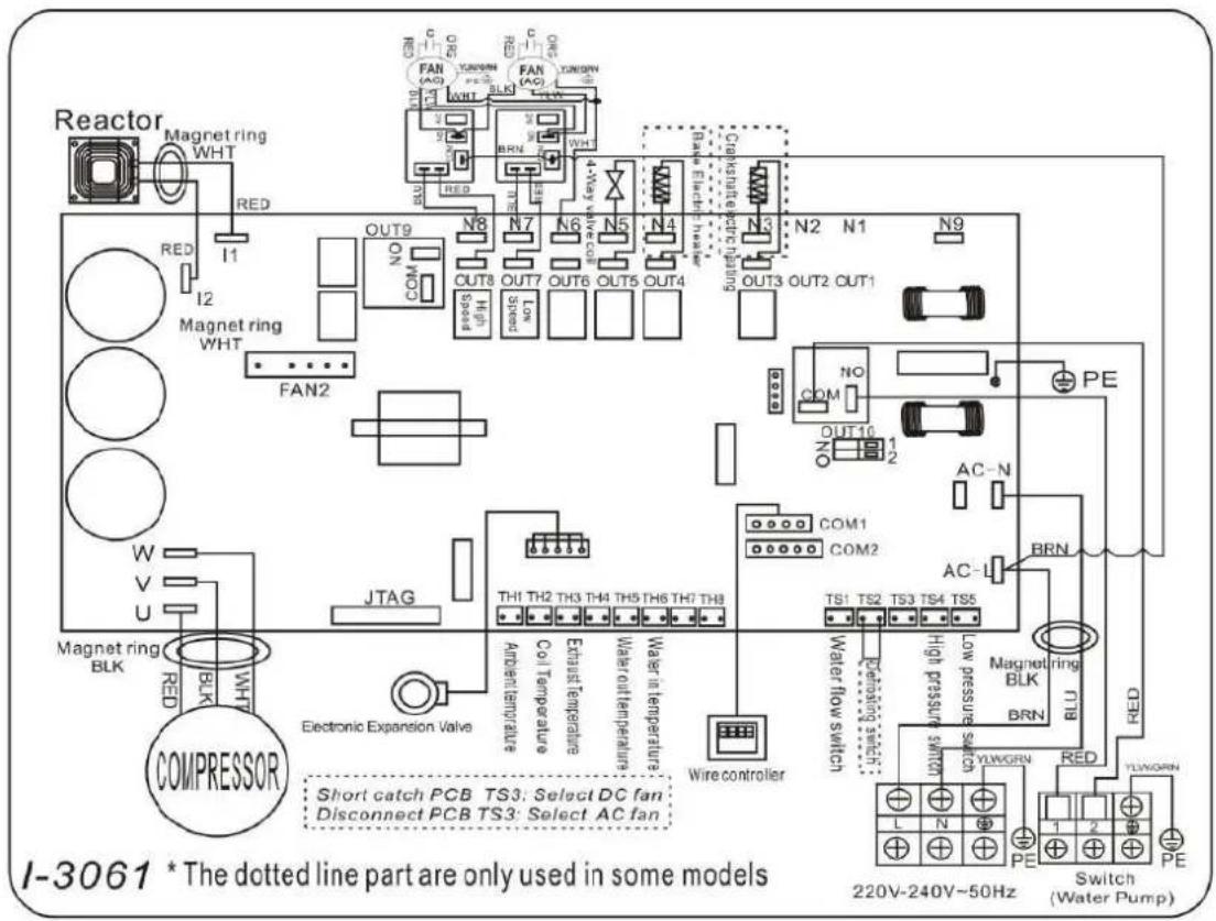
Ref: BEXP25i
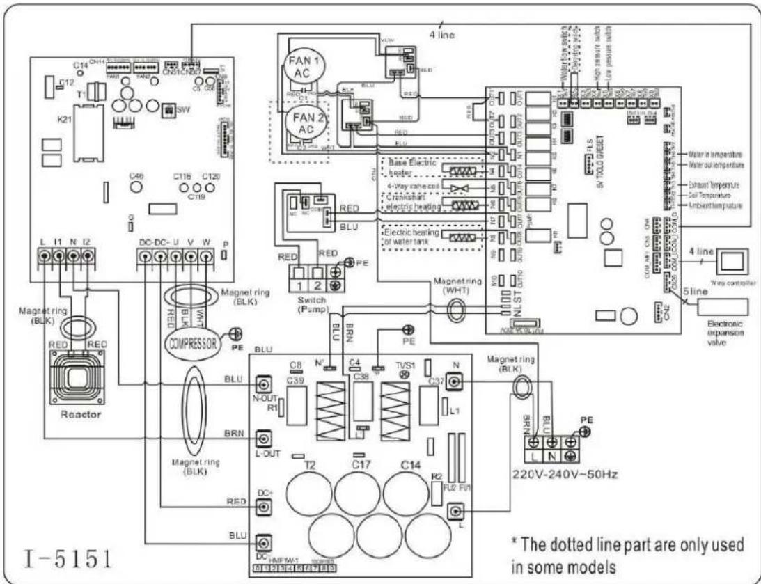
OPMERKING:
BEXP05i/BEXP07i/BEXP09i
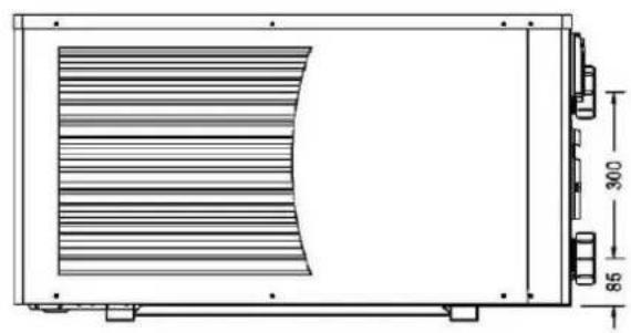

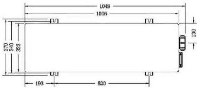


BEXP20i
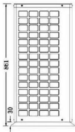
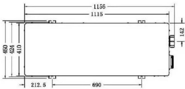

BEXP25i/BEXP30i


Norma CE, R32, Steel Cabinet
| Model | BEXP05i | BEXP07i | BEXP09i | BEXP11i | BEXP14i | |
| * Rendimiento en aire 28 °C, agua 28 °C, humedad 80% | ||||||
| Potencia Calor | kW | 5-3.2 | 7-3.3 | 9-3.5 | 11-4.8 | 14-5 |
| Consumo de energia | kW | 0.98-0.43 | 1.32-0.43 | 1.61-0.43 | 1.96-0.6 | 2.5-0.63 |
| C.O.P. | 7.4-5.1 | 7.7-5.3 | 8.5-5.6 | 8.5-5.6 | 8.5-5.6 | |
| * Rendimiento en aire 15 °C, agua 26 °C, humedad 70% | ||||||
| Potencia Calor | kW | 3.7-2.3 | 4.7-2.4 | 6.6-2.5 | 7.9-3.5 | 9.5-3.6 |
| Consumo de energia | kW | 0.93-0.43 | 1.18-0.43 | 1.65-0.43 | 1.98-0.6 | 2.38-0.62 |
| C.O.P. | 5.4-4 | 5.6-4 | 5.8-4 | 5.8-4 | 5.8-4 | |
| * Rendimiento en aire 0 °C, agua 26 °C, humedad 78% | ||||||
| Potencia Calor | kW | 2.76-1.7 | 3.5-2.0 | 4.50-2.3 | 5.5-3.0 | 7-3.2 |
| Consumo de energia | kW | 0.99-0.40 | 1.25-0.48 | 1.61-0.55 | 1.96-0.71 | 2.5-0.76 |
| C.O.P. | 4.2-2.8 | 4.2-2.8 | 4.2-2.8 | 4.2-2.8 | 4.2-2.8 | |
| Tipo de comprasor | MITSUBISHI INVERTER COMPRESSOR | |||||
| Voltaje | V | 220~240V / 50Hz or 60Hz /1PH | ||||
| Corriente nominal | A | 4.40 | 5.90 | 7.20 | 8.70 | 11.00 |
| Fusible minimo | A | 7.00 | 9.00 | 11.00 | 13.00 | 17.00 |
| Volumen de piscina | m³ | 0-15 | 10-25 | 15-30 | 20-60 | 20-66 |
| Caudal de aguaoptimo | m³/h | 2.50 | 2.50 | 2.80 | 3.70 | 4.00 |
| Caía de presión de agua | Kpa | 12 | 12 | 12 | 14 | 15 |
| Intercambiador de calor | Twist-titanium tube in PVC | |||||
| Conexión de agua | mm | 50 | ||||
| No de ventiladores | 1 | |||||
| Velocidad del ventilador | RPM | 650-870 | 650-850 | |||
| Consumo de ventilador | W | 80 | 200 | |||
| Nivel de ruido (10m) | dB(A) | 36-42 | 37-42 | 37-43 | 39-45 | 40-46 |
| Nivel de ruido (1m) | dB(A) | 44-51 | 45-52 | 45-52 | 46-54 | 47-56 |
| Refrigerante (R32) | g | 400 | 500 | 650 | 750 | 950 |
| CO2 equivalente | Tonne | 0.27 | 0.34 | 0.44 | 0.51 | 0.64 |
| Peso neto | kg | 52.00 | 54.00 | 56.00 | 68.00 | 73.00 |
| Peso bruto | kg | 64.00 | 66.00 | 68.00 | 73.00 | 78.00 |
| Dimisión neta | mm | 1049*375*551 | 1086*450*693 | |||
| Dimisión de embalaje | mm | 1110*430*705 | 1140*495*855 | |||
Norma CE, R32, Steel Cabinet
| Model | BEXP16i | BEXP18i | BEXP20i | BEXP25i | BEXP30i | |
| * Rendimiento en aire 28 °C, agua 28 °C, humedad 80% | ||||||
| Potencia Calor | kW | 16-5.3 | 17.5-5.3 | 19-4.7 | 24-5.9 | 28.5-6.8 |
| Consumo de energia | kW | 2.85-0.66 | 3.21-0.6 | 3.39-0.59 | 4.29-0.74 | 5.09-0.85 |
| C.O.P. | 8.5-5.6 | 8.5-5.6 | 8.5-5.6 | 8.5-5.6 | 8.5-5.6 | |
| * Rendimiento en aire 15 °C, agua 26 °C, humedad 70% | ||||||
| Potencia Calor | kW | 11.2-3.8 | 12.5-3.8 | 14-3.9 | 17.2-4.7 | 22.8-5.6 |
| Consumo de energia | kW | 2.8-0.66 | 3.12-0.6 | 3.5-0.67 | 4.3-0.81 | 5.7-0.97 |
| C.O.P. | 5.8-4 | 5.8-4 | 5.8-4 | 5.8-4 | 5.8-4 | |
| * Rendimiento en aire 0 °C, agua 26 °C, humedad 78% | ||||||
| Potencia Calor | kW | 7.11-4.1 | 8.15-4.4 | 9.3-4.8 | 12-6.7 | 15.1-8.5 |
| Consumo de energia | kW | 2.54-0.95 | 2.91-1.0 | 3.32-1.09 | 4.29-1.53 | 5.34-1.95 |
| C.O.P. | 4.3-2.8 | 4.3-2.8 | 4.4-2.8 | 4.4-2.8 | 4.4-2.8 | |
| Tipo de compresor | MITSUBISHI INVERTER COMPRESSOR | |||||
| Voltaje | V | 220~240V / 50Hz or 60Hz /1PH | ||||
| Corriente nominal | A | 11.90 | 14.30 | 15.00 | 19.00 | 22.60 |
| Fusible minimo | A | 18.00 | 22.00 | 23.00 | 29.00 | 34.00 |
| Volumen de piscina | m³ | 30-85 | 30-90 | 55-120 | 65-130 | 75-180 |
| Caudal de aguaoptimo | m³/h | 4.60 | 5.00 | 5.00 | 8.00 | 10.00 |
| Caía de presión de agua | Kpa | 15 | 15 | 18 | 20 | 25 |
| Intercambiador de calor | Twist-titanium tube in PVC | |||||
| Conexión de agua | mm | 50 | ||||
| N° de ventiladores | 1 | 2 | ||||
| Velocidad del ventilador | RPM | 650-850 | 450-650 | (650-850)*2 | ||
| Consumo de ventilador | W | 200 | 150 | 200*2 | ||
| Nivel de ruido (10m) | dB(A) | 40-46 | 40-46 | 42-48 | 42-49 | 42-51 |
| Nivel de ruido (1m) | dB(A) | 47-56 | 47-56 | 49-58 | 49-59 | 50-60 |
| Refrigerante (R32) | g | 1100 | 1300 | 1500 | 1800 | 2300 |
| CO2 equivalente | Tonne | 0.74 | 0.88 | 1.01 | 1.22 | 1.55 |
| Peso neto | kg | 78.00 | 80.00 | 98.00 | 117.00 | 128.00 |
| Peso bruto | kg | 83.00 | 85.00 | 113.00 | 135.00 | 146.00 |
| Dimisión neta | mm | 1086*450*693 | 1118*455*860 | 1100*452*1280 | ||
| Dimisión de embalaje | mm | 1140*495*855 | 1215*510*1015 | 1156*500*1425 | ||
Tset-1 = 28-1 = 27 °C
Tset +1 = 28 + 1 = 29
BEXP05i/BEXP07i/BEXP09i


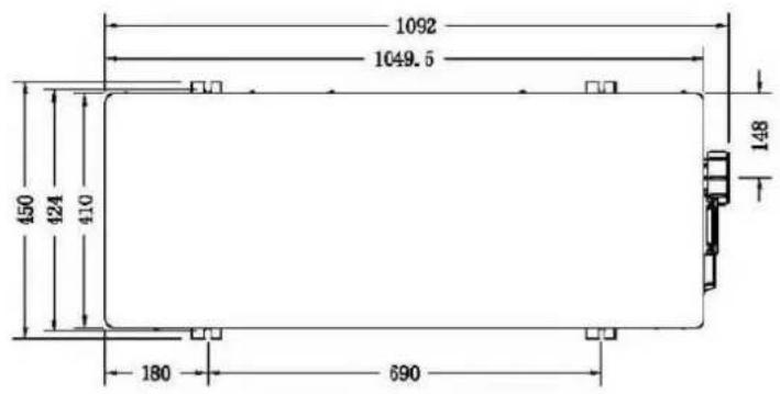
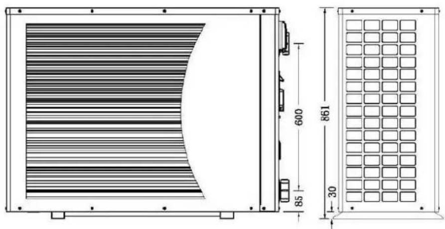
BEXP20i

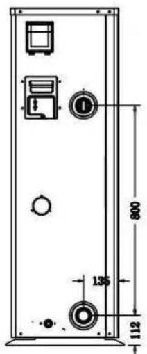
BEXP25i/BEXP30i
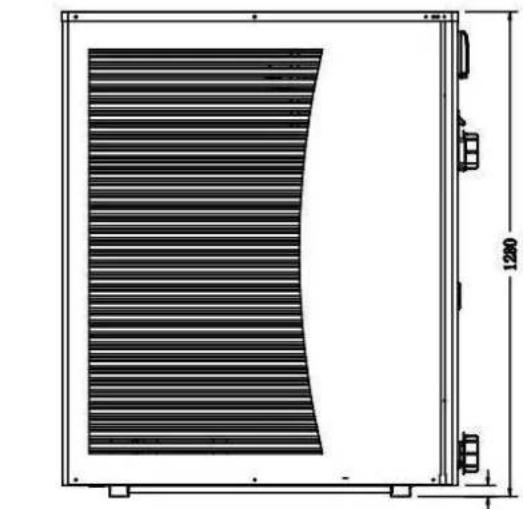
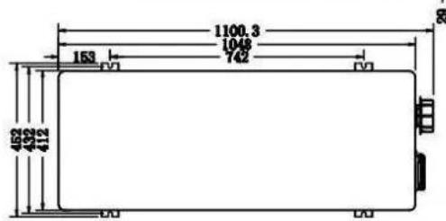
2. Transportinformationen
Ref: BEXP05i/BEXP07i/BEXP09i/BEXP11i/BEXP14i/BEXP16i/BEXP18i/BEXP20i

Ref: BEXP25i
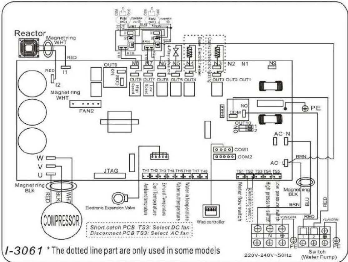
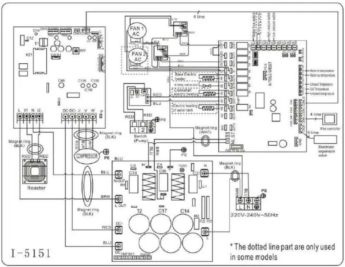
Tset = Tsetting Wassertemperature
Tset-1 = less 1^ than Tsetting temperatur
Tset-1 = 28 - 1 = 27^
Tset+1= more 1^ than Tsetting temperatur
Tset+1=28+1=29°C
8.2 Heizungsglogik
BEXP05i/BEXP07i/BEXP09i


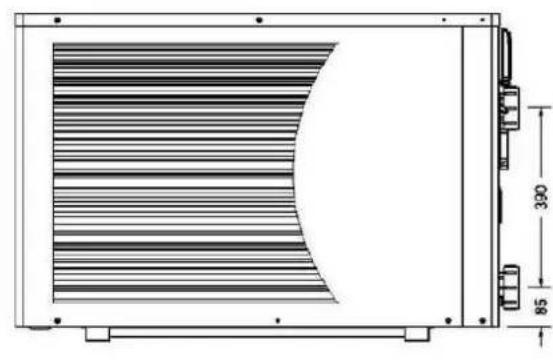
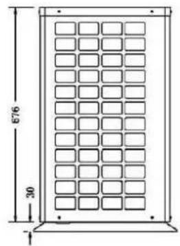
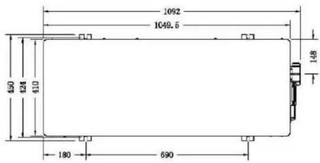

BEXP20i
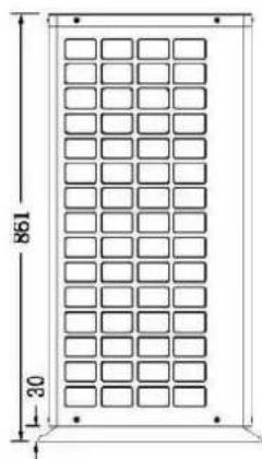
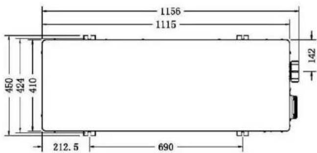
BEXP25i/BEXP30i

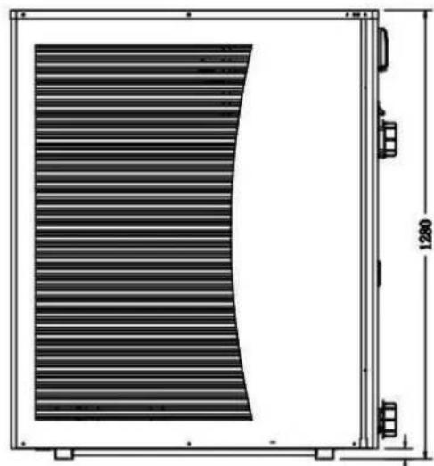

Ref: BEXP05i/BEXP07i/BEXP09i/BEXP11i/BEXP14i/BEXP16i/BEXP18i/BEXP20i

Ref: BEXP25i
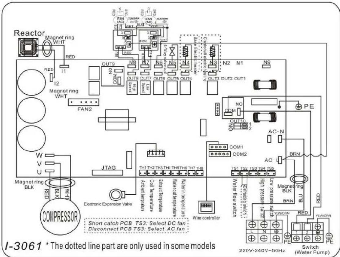

NOTA:
BEXP05i/BEXP07i/BEXP09i
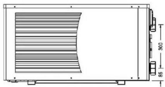
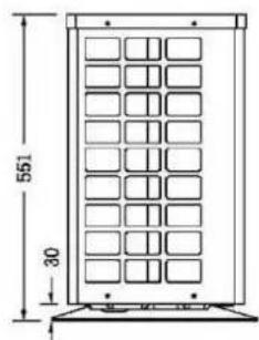
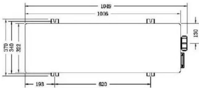
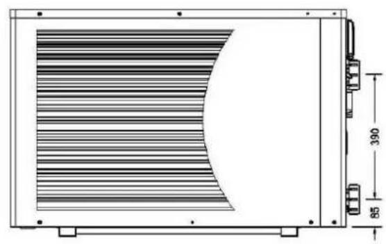


BEXP20i

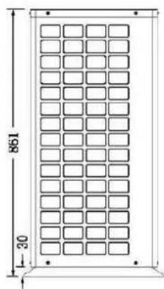
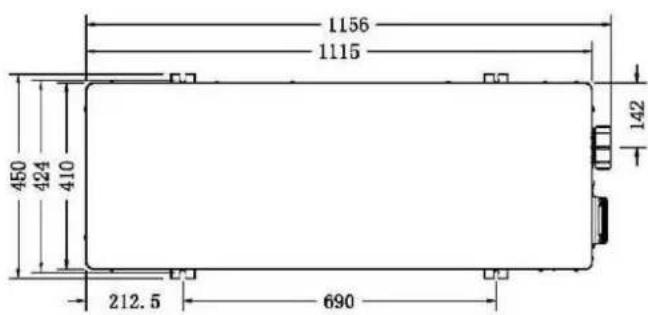
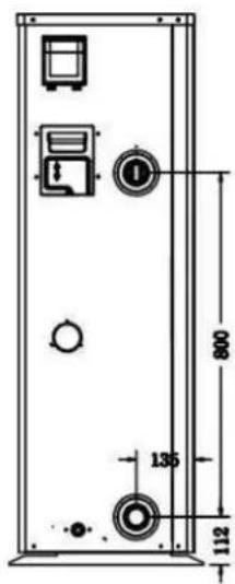
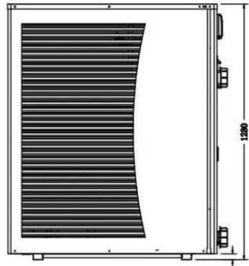

2. Publicidade de transporte
CE Standard, R32, Steel Cabinet
| Model | BEXP16i | BEXP18i | BEXP20i | BEXP25i | BEXP30i | |
| * Desempenho no ar 28 °C, água 28 °C, umidade 80% | ||||||
| Saía de calor | kW | 16-5.3 | 17.5-5.3 | 19-4.7 | 24-5.9 | 28.5-6.8 |
| Entrada de energia | kW | 2.85-0.66 | 3.21-0.66 | 3.39-0.59 | 4.29-0.74 | 5.09-0.85 |
| C.O.P. | 8.5-5.6 | 8.5-5.6 | 8.5-5.6 | 8.5-5.6 | 8.5-5.6 | |
| * Desempenho no ar 15 °C, agua 26 °C, umidade 70% | ||||||
| Saía de calor | kW | 11.2-3.8 | 12.5-3.8 | 14-3.9 | 17.2-4.7 | 22.8-5.6 |
| Entrada de energia | kW | 2.8-0.66 | 3.12-0.66 | 3.5-0.67 | 4.3-0.81 | 5.7-0.97 |
| C.O.P. | 5.8-4 | 5.8-4 | 5.8-4 | 5.8-4 | 5.8-4 | |
| *Desempenho no ar 0 °C, agua 26 °C, umidade 78% | ||||||
| Saía de calor | kW | 7.11-4.1 | 8.15-4.45 | 9.3-4.8 | 12-6.7 | 15.1-8.5 |
| Entrada de energia | kW | 2.54-0.95 | 2.91-1.03 | 3.32-1.09 | 4.29-1.53 | 5.34-1.95 |
| C.O.P. | 4.3-2.8 | 4.3-2.8 | 4.4-2.8 | 4.4-2.8 | 4.4-2.8 | |
| Compressor type | MITSUBISHI INVERTER COMPRESSOR | |||||
| Voltagem | V | 220~240V / 50Hz or 60Hz /1PH | ||||
| Corrente nominal | A | 11.90 | 14.30 | 15.00 | 19.00 | 22.60 |
| Fusível minimo | A | 18.00 | 22.00 | 23.00 | 29.00 | 34.00 |
| Volume de pool recommendado | m³ | 30-85 | 30-90 | 55-120 | 65-130 | 75-180 |
| Aconselhou o fluxo de água | m³/h | 4.60 | 5.00 | 5.00 | 8.00 | 10.00 |
| Queda de pressão de água | Kpa | 15 | 15 | 18 | 20 | 25 |
| Troçador de calor | Twist-titanium tube in PVC | |||||
| Conexão de água | mm | 50 | ||||
| No. de fã | 1 | 2 | ||||
| Velocidade do ventilador | RPM | 650-850 | 450-650 | (650-850)*2 | ||
| Entrada de energia do | W | 200 | 150 | 200*2 | ||
| Nível de ruído (10m) | dB(A) | 40-46 | 40-46 | 42-48 | 42-49 | 42-51 |
| Nível de ruído (1 m) | dB(A) | 47-56 | 47-56 | 49-58 | 49-59 | 50-60 |
| Refrigerante (R32) | g | 1100 | 1300 | 1500 | 1800 | 2300 |
| EQUIVALEnte de CO2 | Tonne | 0.74 | 0.88 | 1.01 | 1.22 | 1.55 |
| Peso líquido | kg | 78.00 | 80.00 | 98.00 | 117.00 | 128.00 |
| Peso bruto | kg | 83.00 | 85.00 | 113.00 | 135.00 | 146.00 |
| Dimensão net | mm | 1086*450*693 | 1118*455*860 | 1100*452*1280 | ||
| Dimensão da embalagem | mm | 1140*495*855 | 1215*510*1015 | 1156*500*1425 | ||
4.3 Accessories Installation
Ref: BEXP05i/BEXP07i/BEXP09i/BEXP11i/BEXP14i/BEXP16i/BEXP18i/BEXP20i

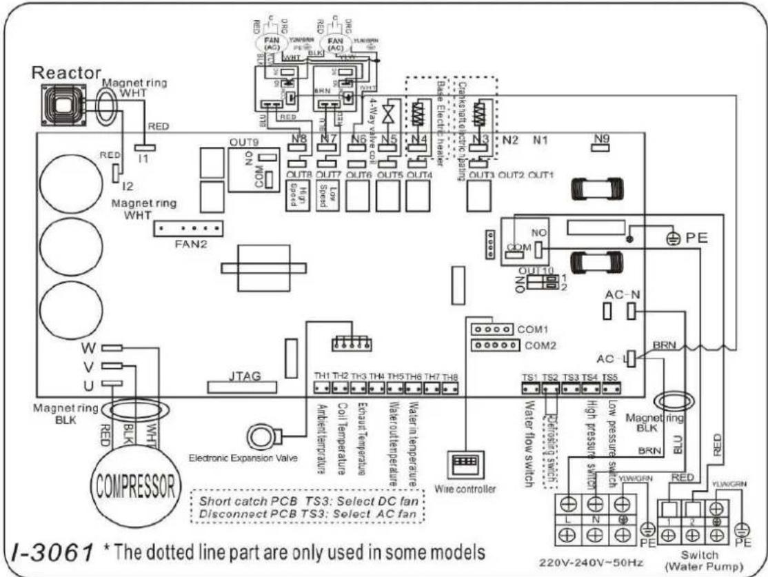
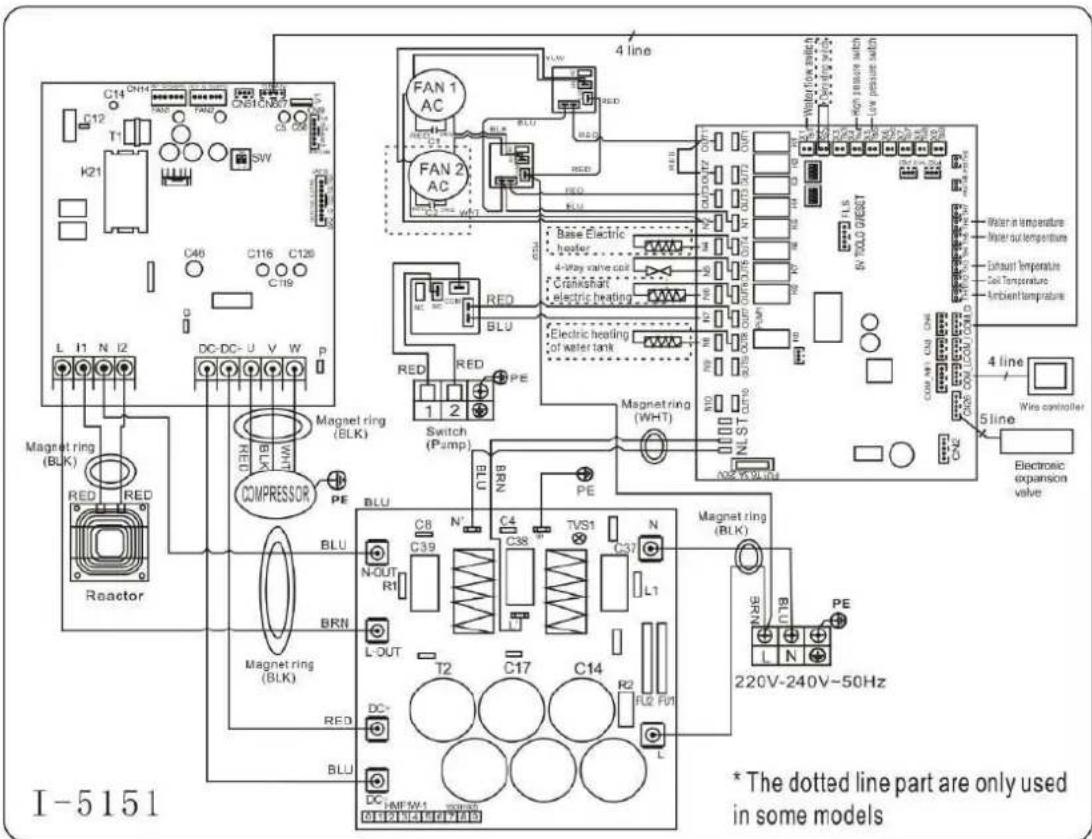
Ref: BEXP30i
NOTA:
Tset-1 = less 1^ than Tsetting temperatura
Tset-1=28-1=27°C
Tset+1= more 1^ than Tseting temperatura
Tset+1=28+1=29°C
1.1 In accordance with these provisions, the seller guarantees that the product corresponding to guarantee ("the Product") is in perfect condition at the time of delivery.
1.2 The Guarantee Term for the Product is two (2) years from the time it is delivered to the purchaser.
1.3 In the event of any defect in the Product that is notified by the purchaser to the seller Guarantee Term, the seller will be obliged to repair or replace the Product, at his own cost and wherever he deems suitable, unless this is impossible or unreasonable.
1.4If it is not possible to repair or replace the Product, the purchaser may ask for a proportion of reduction in the price or, if the defect is sufficiently significant, the termination of the sales contract. 1.5The replaced or repaired parts under this guarantee, will not extend the guarantee period of the original Product, but will have a separate guarantee.
1.6In order for this guarantee to come into effect, the purchaser must provide proof of the date purchase and delivery of the Product.
1.7 If, after six months from the delivery of the Product to the purchaser, he notifies a defect Product, the purchaser must provide proof of the origin and existence of the alleged defect.
1.8 This Guarantee Certificate is issued without prejudice to the rights corresponding to consumer under national regulations.
2 INDIVIDUAL TERMS
2.1 This guarantee covers the products referred to in this manual.
2.2 This Guarantee Certificate will only be applicable in European Union countries.
2.3 For this guarantee to be effective, the purchaser must strictly follow the Manufacturer's instructions included in the documentation provided with the Product, in cases where it is applicable according to the range and model of the Product.
2.4 When a time schedule is specified for the replacement, maintenance or cleaning of certain or components of the Product, the guarantee will only be valid if this time schedule has been followed.
3 LIMITATIONS
3.1 This guarantee will only be applicable to sales made to consumers, understanding by "consumer", a person who purchases the Product for purposes not related to his professional acti
3.2 The normal wear resulting from using the product is not guaranteed. With respect to expen or consumable parts, components and/or materials, such as batteries, light bulbs, etc. the stipulations in the documentation provided with the Product, will apply.
3.3 The guarantee does not cover those cases when the Product; (I) has been handled incorrect has been repaired, serviced or handled by non- authorised people or (III) has been repaired or not using original parts. In cases where the defect of the Product is a result of incorrect instal start-up, this guarantee will only apply when said installation or start-up is included in the sales contract of the Product and has been conducted by the seller or under his responsibility.
ES-CERTIFICADO DE
GARANTÍA 1 ASPECTOS
GENERALES
1.1 In order to reduce the amount of waste of electric and electronic apparatus, to reduce the of components, to encourage the reuse of apparatus, to assess waste and to set up a suitable v treatment system, with the aim of improving the efficiency of environmental protection, a set of has been established applicable to the manufacture of the product and other rules regarding the environmental treatment when these products become waste.
1.2 It is also intended to improve the environmental practices of all agents involved in electronic electronic goods, including manufacturers, distributors, users and particularly those directly involved in the treatment of waste derived from these apparatus.
1.3 From 13th August 2005, there are two ways of disposing of this apparatus:
1.4 If you purchase a new equivalent apparatus or which has the same functions as the one you to dispose of, you can hand it over, free of charge, to the distributor when making your purchase, or
1.5 You can take it to local collection points.
1.6 We shall cover waste treatment costs.
1.7 The apparatus are labelled with a symbol of a "crossed-out waste container". This symbol means that the apparatus is subject to selected waste collection, different from general waste collection.
1.8 Our products are designed and manufactured with top-quality, environmental-friendly materials and components, which can be reused and recycled. In spite of this, several parts of this product not biodegradable and therefore it should not be left in the environment. For the correct recycling of this product, please completely detach the electrical motor from the rest of the filtration equipment.

ES - CONTENEDOR DE BASURA CON RUEdas TACHADO
-The products listed above are in compliance with the safety prescriptions:
2014/30/EU Electromagnetic compatibility Directive (EMC)
2014/35/EU Low voltage Directive (LVD)
2011/65/EU European Directive (RoHS)
EU REACH regulation 1907/2006.
2012/19/EU WEEE
2006/42/EC Machine directice
-Los produits arriba enumerados se hallan conformes con:
- Directa de compatibilidad electromagnética 2014/30/EU (EMC)
- Direcva de equipos de baja tension 2014/35/EU (LVD)
- Directa Europea 2011/65/EU (RoHS)
- Reglamento REACH 1907/2006.
2012/19/EU WEEE
2006/42/CE Directiva de maquinas