DD0203 - Detector IFM - Free user manual and instructions
Find the device manual for free DD0203 IFM in PDF.

User questions about DD0203 IFM
0 question about this device. Answer the ones you know or ask your own.
Ask a new question about this device
Download the instructions for your Detector in PDF format for free! Find your manual DD0203 - IFM and take your electronic device back in hand. On this page are published all the documents necessary for the use of your device. DD0203 by IFM.
USER MANUAL DD0203 IFM
natural_image
Abstract geometric icon with stylized white lines and a circular background (no text or symbols)CE
natural_image
Pure technical diagram of a vertical panel with circular components and mounting brackets (no text or symbols)Inhalt
flowchart
graph TD
    A["D200"] --> B["Motor"]
    A --> C["Terminal Block 1"]
    A --> D["Terminal Block 2"]
    A --> E["Terminal Block 3"]
    A --> F["Terminal Block 4"]
    A --> G["Terminal Block 5"]
    H["Control Unit ①"] --> A
    I["Control Unit ②"] --> A
    J["Control Unit ③"] --> A
    K["Control Unit ④"] --> A
    L["Control Unit ⑤"] --> A
DE
natural_image
Pure technical diagram of a mechanical component with no text, numbers, or symbols
natural_image
Technical line drawing of a structural frame with mounting bracket and wall detail (no text or symbols)natural_image
Technical diagram showing a mechanical assembly with a tool and directional arrow (no text or symbols)text_image
BN BK BU + - 几 5 6 7text_image
BN BU 5 6
BN = braun (brown) BK = schwarz (black) BU = blau (blue) WH = weiß (white)

1 Preliminary note ....4
1.1 Symbols used ....4
1.2 Warning signs used ....4
2 Safety instructions ....5
2.1 General 5
2.2 Target group....5
2.3 Electrical connection ....5
2.4 Handling 6
2.5 Installation location 6
2.6 Housing temperature 6
2.7 Tampering with the device 6
3 Functions and features ....7
4 Operating and display elements ....8
4.1 LEDs 8
4.2 Potentiometer 9
5 Installation....10
5.1 Installation of the device ....10
5.1.1 Remove the device ....10
5.2 Mounting of the sensors ....10
6 Electrical connection 11
6.1 Connection accessories 11
6.2 Terminal connection 11
6.3 Voltage supply (power) 12
6.3.1 AC supply 12
6.3.2 DC supply 12
6.4 Inputs 12
6.4.1 Connection of the sensor 12
6.4.2 Enable input....13
6.5 Outputs ....13
6.5.1 Relay output 13
6.5.2 Transistor output 13
7 Settings....14
7.1 Frequency range and switching function (function) .....14
2
7.1.1 Frequency range (SPx1/SPx100) 14
7.1.2 Switching function I...IV 14
7.2 Switch point (SP) 15
7.3 Hysteresis 15
7.4 Start-up delay 16
7.5 Switching diagram 17
7.5.1 With start-up delay and coupled voltage supplies .....17
7.5.2 With start-up delay and enable signal coupled to the motor .....18
8 Scale drawing 19
9 Technical data ....1
9.1 Approvals/standards ......20
10 Troubleshooting 21
11 Maintenance, repair, disposal ....21
11.1 Maintenance 21
11.2 Cleaning the housing surface 21
11.3 Repair 21
11.4 Disposal 21
This document is the original instructions.
1 Preliminary note
This document applies to devices of the type "speed monitor D200".
The devices differ in the following points:
setting range of the switch point SP [Hz] ( 4 Operating and display elements).
This document is intended for specialists. These specialists are people who are qualified by their training and their experience to see risks and to avoid possible hazards that may be caused during operation, installation or maintenance of the device.
Read this document before use to familiarise yourself with operating conditions, installation and operation. Keep this document during the entire duration of use of the device.

WARNING
Adhere to the warning notes and safety instructions (→ 2 Safety instructions).
1.1 Symbols used
▶ Instructions
Reaction, result
[...] Designation of keys, buttons or indications
→ Cross-reference

Important note
Non-compliance can result in malfunction or interference.

Information
Supplementary note.
1.2 Warning signs used

WARNING
Warning of serious personal injury.
Death or serious irreversible injuries may result.

CAUTION
Warning of personal injury.
Slight reversible injuries may result.
NOTE
Warning of damage to property.
2 Safety instructions
2.1 General
Follow the operating instructions. Non-observance of the instructions, operation which is not in accordance with use as prescribed below, wrong installation or incorrect handling can affect the safety of operators and machinery.
The installation and connection must comply with the applicable national and international standards. Responsibility lies with the person installing the device.
The system installer is responsible for the safety of the system into which the device is integrated.
2.2 Target group
The device must only be installed, connected and put into operation by a qualified electrician.
2.3 Electrical connection
Disconnect the unit externally before handling it. Also disconnect any independently supplied relay load circuits.
Make sure that the external voltage is generated and supplied according to the requirements for safety extra-low voltage (SELV) since this voltage is supplied without further measures near the operating elements and at the terminals for the supply of connected sensors.
The wiring of all signals in connection with the SELV circuit of the device must also comply with the SELV criteria (safety extra-low voltage, safe electrical isolation from other electric circuits).
If the externally supplied or internally generated SELV voltage is externally grounded, the responsibility lies with the user in accordance with the applicable national installation regulations. All statements in these operating instructions refer to the unit the SELV voltage of which is not grounded.
It is not allowed to supply external voltage to the terminals for the pulse pick-up supply. The consumption of current which exceeds the value given in the technical data is not allowed.
An external main switch must be installed for the unit which can switch off the unit and all related circuits. This main switch must be clearly assigned to the unit.
2.4 Handling
Be careful when handling the unit once power is applied. This is only allowed by qualified personnel due to the protection rating IP 20.
2.5 Installation location
For the correct operation the device must be mounted in a housing which can only be opened using a tool or in a locked control cabinet (both protection rating IP 54 or higher) as an enclosure in accordance with EN 61010.
2.6 Housing temperature
As described in the technical specifications below the device can be operated in a wide ambient temperature range. Because of the additional internal heating the operating elements and the housing walls can have high perceptible temperatures when touched in hot environments.
2.7 Tampering with the device
In case of malfunction of the unit or queries please contact the manufacturer. Any tampering with the device can seriously affect the safety of operators and machinery. This is not permitted and leads to the exclusion of any liability and warranty claims.
3 Functions and features
The D200 speed monitor is a pulse evaluation system. It monitors rotating, linear, vibrating or oscillating movements.
It receives the pulses from external sensors, measures the pulse interval and calculates the input frequency. This value is compared with the set switch points; the outputs are switched in accordance with the set parameters.
flowchart
graph TD
    A["D200 Device"] -->|①| B["Control Unit"]
    A -->|②| C["Motor"]
    A -->|③| D["Inductors"]
    A -->|④| E["Inductors"]
    A -->|⑤| F["Inductors"]
    style A fill:#f9f,stroke:#333
    style B fill:#ccf,stroke:#333
    style C fill:#cfc,stroke:#333
    style D fill:#fcc,stroke:#333
    style E fill:#cff,stroke:#333
    style F fill:#ffc,stroke:#333
Example: speed monitoring of a motor shaft on a conveyor belt
1: Conveyor belt
2: Pulse pick-up on the motor shaft
3: Relay output
4: Transistor output
5: Signals depending on the selected switching function

WARNING
The device is not approved for safety-related tasks in the field of operator protection.
4 Operating and display elements
text_image
Power Input Output Enable SPx1 IV I II SPx100 I II IV 1 0,110 50 1 -100 5 10 0,1 -15 SPDelayFunction (Hz) Hysteresis (%) (sec)Example: device with switch point range 0.1...10 Hz and 10...1000 Hz
1: LEDs
2: Potentiometer
3: Panel for labelling
4.1 LEDs
| LED Colour | Status Description | tion | |
| Power Green | On Voltage supply | OK | |
| Flashing Potentiometer "Function" in invalid setting zone (→7.1) | |||
| Input Yellow | Flashing Input pulses | ||
| Output | Green On Relay energised | Transistor switched | |
| Enable | Yellow | On Enable input | switched (+24 V DC is applied to the enable input) Start-up delay active |
Error signals and diagnosis ( 10 Troubleshooting)
4.2 Potentiometer
| Potentiometer Setting | ||
| Function Frequency | range [SPx1/SPx100] (→ 7.1.1) | |
| Switching function [I...IV] (→ 7.1.2) | ||
| SP Switch point [Hz]The adjustable frequency value depends on the potentiometer position "Function". | (→ 7.2) | |
| Hysteresis Hysteresis [%] (→ 7.3) | ||
| Delay Start-up delay [s] (→ 7.4) | ||
UK
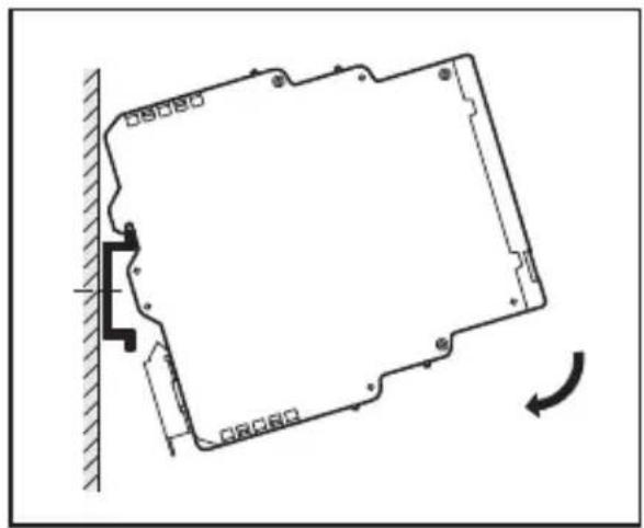
5 Installation
5.1 Installation of the device
▶ Install the device on a 35 mm DIN rail.
natural_image
Pure technical diagram of a mechanical component with no text, numbers, or symbols
natural_image
Technical line drawing of a structural frame with mounting brackets and a wall corner (no text or symbols)Leave enough space between the unit and the top and bottom of the control cabinet to enable air circulation and to avoid excessive heating.
▶ Take into account the internal heating of all units when mounting several units side by side. The environmental conditions must be observed for every unit.
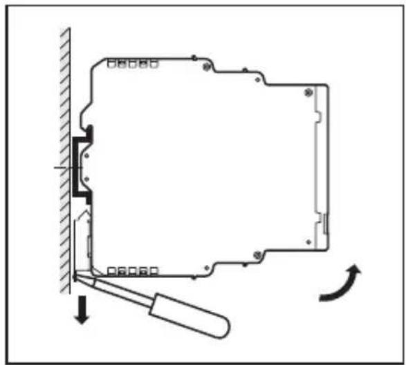
5.1.1 Remove the device
natural_image
Diagram of a mechanical assembly with a tool and directional arrows indicating motion (no text or symbols)5.2 Mounting of the sensors
Follow the manufacturer's installation instructions.
6 Electrical connection
6.1 Connection accessories
The unit is supplied including the connector.
You can find more information about the available accessories at: www.ifm.com → Data sheet search → Article number → Accessories
6.2 Terminal connection
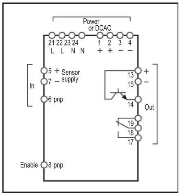
flowchart
graph TD
    A["Power or DCAC"] --> B["In"]
    B --> C["5 + Sensor supply"]
    B --> D["7 - supply"]
    B --> E["6 pnp"]
    B --> F["Enable"]
    A --> G["Out"]
    G --> H["13 +"]
    G --> I["15 -"]
    G --> J["14"]
    G --> K["19"]
    G --> L["18"]
    G --> M["17"]
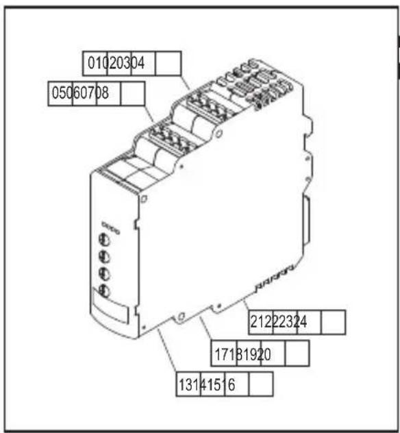
text_image
010 203 04 050 607 08 212 223 24 171 319 20 131 415 16UK
Terminal connection

WARNING
Only the supplied or technically identical connectors may be used on the terminals blocks for the AC supply (21...24) and the relay output (17...20) ( 9 Technical data).
To ensure protection rating IP 20 for the housing and the terminals, fully tighten the screws of the unused connector contacts.

WARNING
Do not use unconnected terminals which are not shown in the drawing such as terminal 20 as support point terminal.
6.3 Voltage supply (power)
▶ Voltage supply see type label.
▶ Connect the device only to one of the possible voltage connections, i.e. either to terminals 21/22 and 23/24 (AC) or to terminals 1/2 and 3/4 (24 V DC).
▶ Lay all supply and signal cables separately. Use a screened cable if required in the application.
6.3.1 AC supply

WARNING
The AC supply cable must be protected according to the cross-section used (max. 10 A).
If the unit is supplied on AC, the low voltage provided for the sensor supply meets the SELV criteria according to EN 61010, overvoltage category II, soiling degree 2.
6.3.2 DC supply
▶ The SELV criteria (safety extra-low voltage) must be met for the DC supply.
The DC supply cable L+ (terminals 1/2) must be protected externally with a 315 mA time-lag fuse (5 x 20 mm or similar).
The DC supply terminals are directly connected to the sensor supply terminals.
6.4 Inputs
6.4.1 Connection of the sensor
3-wire DC PNP 2-wire DC
quadronorm
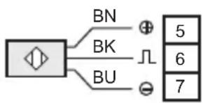
text_image
BN BK BU + - 几 5 6 72-wire AC/DC Mechanical
switch
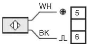
text_image
WH BK 5 6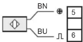
text_image
BN BU 5 6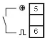
BN = brown
BK = black
BU = blue
WH = white

The connection of mechanical switch contacts is not recommended since they tend to bounce and produce faulty pulses.
The terminals 5 and 7 can be used for the sensor supply or for the enable input.
6.4.2 Enable input
Using the enable input (terminal 8) the start-up delay can be started.
▶ To do so, connect the internal +24 V DC voltage (terminal 5) or an external +24 V DC voltage to terminal 8 via a closing contact.
▶ If an external voltage is used, connect the negative reference point of this voltage to terminal 3 or 4 of the device.

When the contact is open (+24 V DC no longer applied) and the set start-up delay has elapsed monitoring starts.

A +24 V DC continuous signal results in a permanent deactivation of the monitoring. The same state as during the start-up delay is indicated.
UK
6.5 Outputs
6.5.1 Relay output
▶ To prevent excessive wear and to comply with the EMC standards, interference suppression of the contacts is required for switching inductive loads.

WARNING
If the device is operated on an AC supply (terminals 21/22 and 23/24) this must use the same supply cable (phase) as the voltage supply to switch an AC voltage via the relay output.

If the relay output is used to switch very small currents (e.g. PLC input), considerable contact resistance can arise. For this purpose use the transistor output.
6.5.2 Transistor output
The transistor output needs an external +24 V DC supply on terminal 13. Protect this +24 V DC supply cable externally with a 315 mA time-lag fuse (5 x 20 mm or similar).
▶ Connect the reference point (GND) of the external power supply with terminal 15 or 3/4 of the device. Otherwise no switching operation is possible.
The SELV criteria (safety extra-low voltage) must be met for the DC supply of the transistor outputs.
7 Settings
▶ Set the continuously adjustable potentiometers using a suitable screwdriver.
7.1 Frequency range and switching function (function)
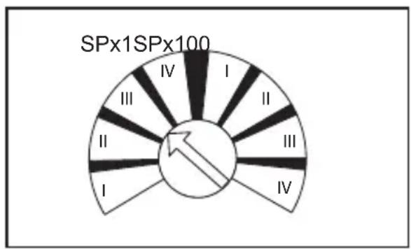
pie
SPx1SPx100 | Category | Value | |---|---| | I | 1 | | II | 2 | | III | 3 | | IV | 4 |□ = valid setting zone
■ = invalid setting zone
Potentiometer "Function"
▶ Note that the setting of the potentiometer is within a valid zone.
If the setting is outside a valid zone, [POWER] flashes.
7.1.1 Frequency range (SPx1/SPx100)
| SPx1 SPx100 | |
| corresponds to the marking on the device corresponds to the marking on device x 100 | |
7.1.2 Switching function I...IV
| I Status signal: minimum speed reached / standstill | |
| II Error signal: underspeed / blocked | |
| III Status signal: speed reached | |
| IV Error signal: overspeed | |
Switching function in combination with switch point, hysteresis and start-up delay ( 7.5 Switching diagram)
7.2 Switch point (SP)
| Value at which the output changes its switching status according to the switching function. | |
| Value according to the marking on the device, e.g. 0.1...10 Hz or 10...1000 Hz (depending on the potentiometer position SPx1/SPx100) |
7.3 Hysteresis
| The hysteresis value determines the difference between the reset point and the switch point SP.If the distance between cams is not the same, different pulse sequence times are measured. They may be alternately above or below the switch point so that the output changes its switching status continuously and rapidly. This behaviour can be prevented by increasing the hysteresis factor. | |
| Value 1...1 | 00 % |
7.4 Start-up delay
Enables the suppression of error signals when a plant is started.
After power on the start-up delay is active only once.
- If the motor is often switched on and off, it is useful to couple the supply voltages of the motor and speed monitor. By doing so, the start-up delay is active every time the motor is turned on.
- If a coupled connection of the voltage supplies is not possible, use the enable input (→ 6.4.2 Enable input).
Value 0.1...15 s
7.5 Switching diagram
7.5.1 With start-up delay and coupled voltage supplies
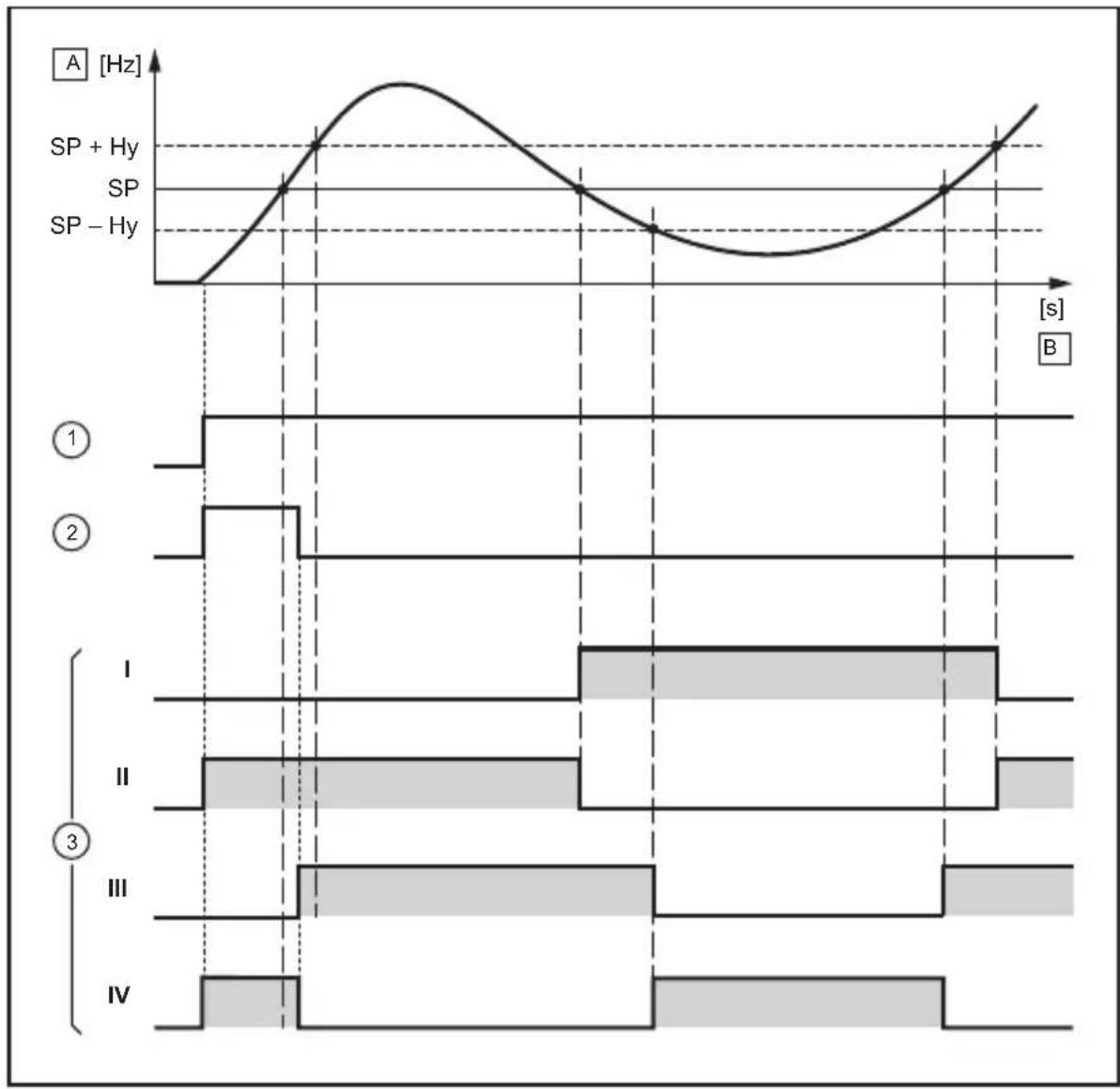
line
| Time Segment | Signal Type | Value Label | | ------------ | ----------- | ----------- | | I | SP | SP + Hy | | II | SP | SP - Hy | | III | SP | SP + Hy | | IV | SP | SP - Hy |1: Voltage supply speed monitor (coupled to the motor)
2: Start-up delay
3: Switching functions
A Input frequency as an indication of speed
B Time
= relay energised, i.e. switched (transistor output switched)
7.5.2 With start-up delay and enable signal coupled to the motor
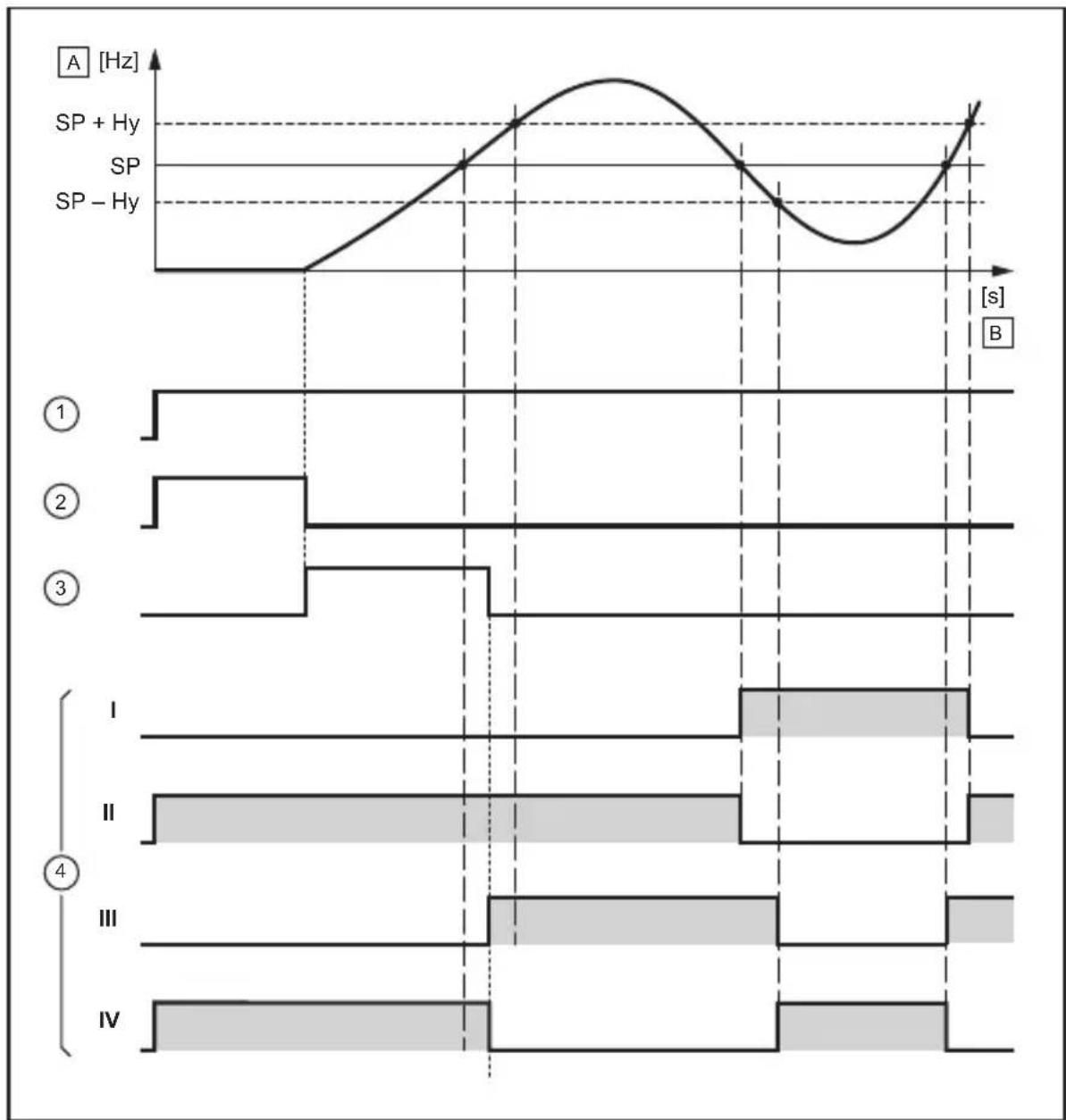
line
| Time Segment | Signal Type | Value Label | | ------------ | ----------- | ----------- | | 1 | SP | SP + Hy | | 2 | SP | SP | | 3 | SP | SP - Hy | | 4 | I | | | 4 | II | | | 4 | III | | | 4 | IV | |1: Voltage supply speed monitor
2: +24 V DC signal at the enable input (coupled to the motor)
3: Start-up delay
4: Switching functions
A: Input frequency as an indication of speed
B: Time
= relay energised, i.e. switched (transistor output switched)
8 Scale drawing
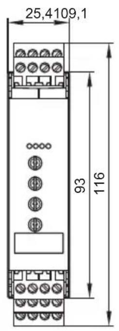
text_image
25,4109,1 93 116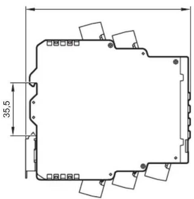
text_image
35,5UK
9 Technical data
| Speed monitor type D200 | ||
| Nominal voltage AC [V] 110....240 | ||
| Nominal frequency [Hz] 50...60 | ||
| Voltage tolerance [%] -20/+10 | ||
| Power consumption [W] 6 | ||
| Alternatively | ||
| Nominal voltage DC [V] 27 (typ. 24) | ||
| Voltage tolerance [%] -20/+10 | ||
| Power consumption [W] 4 | ||
| Auxiliary energy for sensors | [V] | 18.5...30 DC SELV, ≤ 100 mA |
| Sensor type (pulse input) | PNP (type 2 to IEC 61131-2) | |
| Input frequency | [Hz] ≤ 5000 | |
| Relay contact rating [A] 4 | Resistive load (240 V AC or 24 V DC)Electrically isolatedReinforced insulation to EN 61010Overvoltage category II,Degree of soiling 2 to 240 V AC nominal voltage | |
| Transistor switching voltage [V] | 10...30 | DC SELV |
| Transistor current rating [mA] ≤ | 100 | |
| Protection housing / terminals IP | 20 / IP | 20 |
| Ambient temperature [°C] -25... | 60 | |
| Storage temperature [°C] -25... | 70 | |
| Max. perm. relative humidity [%] | 80 (31 °C) | Linearly decreasing to 50 (40 °C)Non condensing |
| Maximum operating altitude [m] | 2000 above sea level | |
| Connection | ||
| Device | 4-pole terminal blocks with 5.0 mm pitch | |
| Connector | 4 poles with screw connection(supplied with the unit) | |
| Type | Phoenix Contact MSTBT 2,5/4-ST BK0.2...2.5 mm^2 (AWG 30...12) | |
Data sheets are available at:
www.ifm.com → Data sheet search → Article number
9.1 Approvals/standards
EC declarations of conformity, approvals etc. can be downloaded at:
www.ifm.com → Data sheet search → Article number → More information
10 Troubleshooting
| LED Error Troubleshooting | |||||
| Power | Input | Output | Enable | ||
| ✕ | --- | ○ | Potentiometer "Function" in invalid setting zone | Correct potentiometer position (→7.1) | |
| Short circuit at sensor supply Remove short circuit | |||||
| Overspeed Check whether the input frequency is outside the permissible frequency range (→9) | |||||
| ✕ | --- | ● | Short circuit at transistor output Remove short circuit | ||
| ○ | -- Internal device error Contact service | ||||
Legend:

off
on

--
any

11 Maintenance, repair, disposal
11.1 Maintenance
The unit is maintenance-free.
11.2 Cleaning the housing surface
▶ Disconnect the device.
▶ Clean the device from dirt using a soft, chemically untreated and dry cloth.

Micro-fibre cloths without chemical additives are recommended.
11.3 Repair
▶ The device must only be repaired by the manufacturer.
Observe the safety instructions.
11.4 Disposal
▶ Dispose of the device in accordance with the national environmental regulations.
Contenu
9.1 Homologations/normes .....21
natural_image
Pure mechanical diagram showing a rectangular frame mounted on a wall, with no text or symbols present.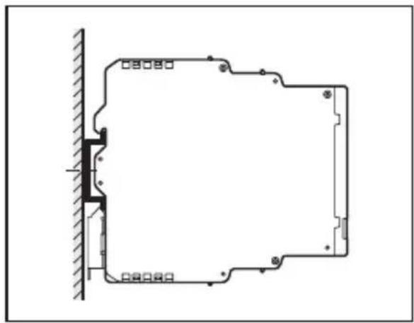
natural_image
Architectural or engineering diagram showing a structural frame with hatched walls and corner brackets (no text or symbols)natural_image
Technical diagram showing a mechanical assembly with a tool and directional arrows, no readable text or symbols present.text_image
BN BU 5 6
BN = brun (brown)
BK = noir (black)
BU = bleu (blue)
WH = blanc (white)