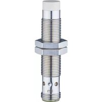
IFP201 - Detector IFM - Free user manual and instructions
Find the device manual for free IFP201 IFM in PDF.


User questions about IFP201 IFM
0 question about this device. Answer the ones you know or ask your own.
Ask a new question about this device
Download the instructions for your Detector in PDF format for free! Find your manual IFP201 - IFM and take your electronic device back in hand. On this page are published all the documents necessary for the use of your device. IFP201 by IFM.
USER MANUAL IFP201 IFM
Operating instructions Performance sensor
IxP20x
1 Preliminary note
You will find instructions, technical data, approvals, accessories and further information using the QR code on the unit / packaging or at www.ifm.com.
1.1 Symbols used
√ Requirement
Instructions
Reaction, result
[...] Designation of keys, buttons or indications
→ Cross-reference

Important note
Non-compliance may result in malfunction or interference.

Information
Supplementary note
2 Safety instructions
- The unit described is a subcomponent for integration into a system.
- The system architect is responsible for the safety of the system.
-
The system architect undertakes to perform a risk assessment and to create documentation in accordance with legal and normative requirements to be provided to the operator and user of the system. This documentation must contain all necessary information and safety instructions for the operator, the user and, if applicable, for any service personnel authorised by the architect of the system.
-
Read this document before setting up the product and keep it during the entire service life.
- The product must be suitable for the corresponding applications and environmental conditions without any restrictions.
- Only use the product for its intended purpose (→ Intended use).
- If the operating instructions or the technical data are not adhered to, personal injury and/or damage to property may occur.
- The manufacturer assumes no liability or warranty for any consequences caused by tampering with the product or incorrect use by the operator.
- Installation, electrical connection, set-up, operation and maintenance of the product must be carried out by qualified personnel authorised by the machine operator.
- Protect units and cables against damage.
3 Intended use
The device detects metal without contact and outputs the distance value in micrometres ( µ m) via IO-Link.
4 Function
The PCB coil and the capacitor form an LC resonant circuit, also known as a basic sensor.
If a target is brought into the sensor field, the inductance changes. The change in inductance is analysed by the external electronics, and a process value is output depending on the distance. Since there is no ferrite core, the devices are insensitive to interference from strong magnetic fields. To equalise material properties and target sizes as well as the installation situation, the device offers two options for an application configuration ( → Application configuration ☐ 12).

The device achieves the accuracies specified in the data sheet after a warm-up time of 15 minutes.

1: Connection
2: Housing
3: External electronics
4: Capacitor
5: Coil
6: Alternating electromagnetic field = active zone
7: Target = electrically conductive material
8: Ideal direction of movement of the target
4.1 Switching function with switch point
A switching signal can be provided for process value monitoring. OUT1 will change its switching status according to the parameter settings as a function of the distance to the object.
You can choose between the following switch point modes according to the IO-Link smart sensor profile:
- Single point mode
- Two point mode
- Window mode
| Term | Explanation |
| H | Hysteresis, can be set via the parameter [HY] |
| High active | Switch-point logic:switching output is switched on object detection = NO (normally open) |
| Low active | Switch-point logic:switching output is not switched on object detection = NC (normally closed) |
| PDV (Process data variable) | Process data value |
| SP | Switch point (SP1 must be greater than SP2) |
| SSC (Switching Signal Channel) | Switching signal channel |
| SSC1 | Switching signal channel 1 |
| SSC2 | Switching signal channel 2 |
| Single point mode | Single switch point mode |
| Two point mode | Two switch point mode |
| Window mode | Window mode |
Tab. 1: definition of terms
Single point mode
Only one switch point (SP1) is manually set or taught. The switch-off point results from the switch point and the set hysteresis (H).

Single point mode – low active
SP1+H: switch-on point
SP1: switch-off point
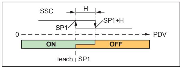
Single point mode – high active
SP1: switch-on point
SP1+H: switch-off point
Two point mode
A switch point (SP1) and a switch-off point (SP2) are manually set or taught.
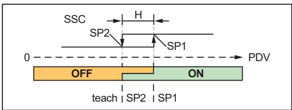
Two point mode – low active
SP2: switch-off point
SP1: switch-on point

Two point mode – high active
SP1: switch-off point
SP2: switch-on point
Window mode
Two switch points (SP1) and (SP2) are manually set or taught. The two switch points delimit a window area.

Window mode – low active
- The output switches off (low active) within the switching limits SP1 and SP2.
- The output switches on (high active) when the process value leaves the window area and the set hysteresis is exceeded: SP1+H or SP2-H.

Window mode – high active
- The output switches on (high active) within the switching limits SP1 and SP2.
- The output switches off (low active) when the process value leaves the window area and the set hysteresis is exceeded: SP1+H or SP2-H.
Conditions for switching points:
• SP1, SP2 between 2xMBA and MBE -3%
- SP1+H, SP2+H < MBE
• H between 3...15%
Diagnostic IO-Link data:
• Upper limit MBE +5 µ m
• Lower limit MBE -5 µ m
4.2 IO-Link
IO-Link is a communication system for connecting intelligent sensors and actuators to automation systems. IO-Link is standardised in the IEC 61131-9 standard.

General information on IO-Link at io-link.ifm

Input Output Device Description (IODD) with all parameters, process data and detailed descriptions of the device at documentation.ifm.com
IO-Link offers the following advantages:
• Interference-free transmission of all data and process values
• Parameter setting in the running process or presetting outside the application
- Parameters for identifying the connected devices in the system
• Additional parameters and diagnostic functions
• Automatic backup and restore of parameter sets in case of device replacement (data storage)
- Logging of parameter sets, process values and events
• Device description file (IODD - Input Output Device Description) for easy project planning
• Standardised electrical connection
- Remote maintenance
5 Installation
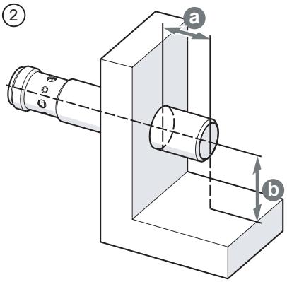
5.1 Installation conditions IFP20x
①

②
③

④

⑥

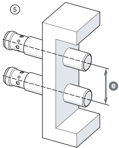
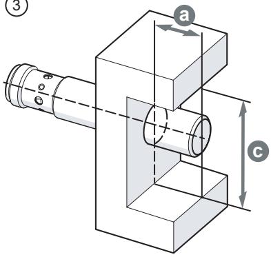
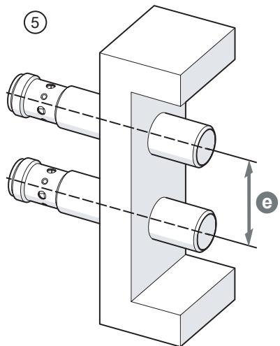
Fig. 1: Installation distances in millimetres
| Application configuration | Target | Type | Installation | a | b | c | d | e | f |
| Factory calibration | aluminium 24x24 | M12 | flush | 6 | 12 | 36 | 24 | - | 8xSn |
| aluminium 36x36 | non-flush | 24 | 18 | 48 | - | 36 | |||
| 1-point calibration | aluminium 24x24 | M12 | flush | 6 | 12 | 36 | 24 | - | |
| aluminium 36x36 | non-flush | 24 | 18 | 48 | - | 36 | |||
| 3-point calibration | steel 12x12 | M12 | flush | 0 | 6 | - | 24 | - | |
| steel 24x24 | non-flush | 10 | 12 | 36 | - | 24 |

Even if the installation situation described is adhered to, an application configuration may be necessary in order to achieve the performance specified in the data sheet.
5.2 Installation conditions IGP20x


③
④

⑥

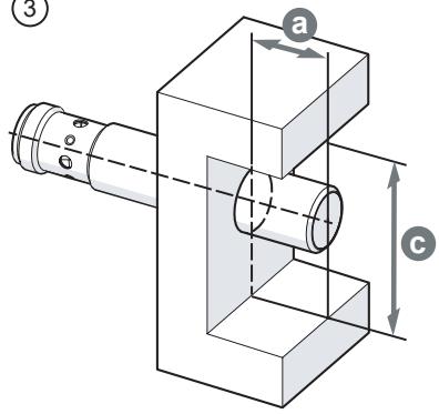
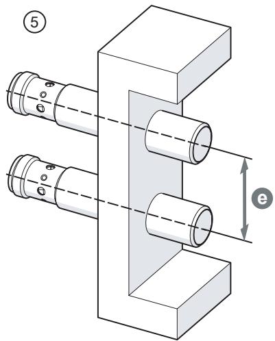
Fig. 2: Installation distances in millimetres
| Application configuration | Target | Type | Installation | a | b | c | d | e | f |
| Factory calibration | aluminium 36x36 | M18 | flush | 9 | 18 | 54 | 36 | - | 8xSn |
| aluminium 54x54 | non-flush | 36 | 27 | 72 | - | 54 | |||
| 1-point calibration | aluminium 36x36 | M18 | flush | 9 | 18 | 54 | 36 | - | |
| aluminium 54x54 | non-flush | 36 | 27 | 72 | - | 54 | |||
| 3-point calibration | steel 18x18 | M18 | flush | 0 | 9 | - | 36 | - | |
| steel 36x36 | non-flush | 15 | 18 | 54 | - | 36 |

Even if the installation situation described is adhered to, an application configuration may be necessary in order to achieve the performance specified in the data sheet.
5.3 Installation conditions IIP20x

③
④

⑥

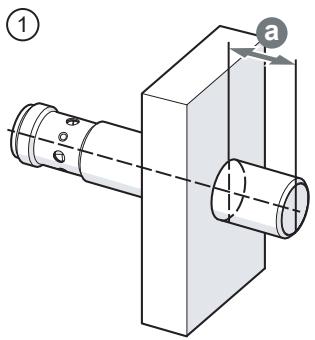
Fig. 3: Installation distances in millimetres
| Application configuration | Target | Type | Installation | a | b | c | d | e | f |
| Factory calibration | aluminium 60x60 | M30 | flush | 15 | 30 | 90 | 60 | - | 8xSn |
| aluminium 120x120 | non-flush | 33 | 60 | 120 | - | 120 | |||
| 1-point calibration | steel 60x60 | M30 | flush | 15 | 30 | 90 | 60 | - | |
| steel 120x120 | non-flush | 33 | 45 | 120 | - | 120 | |||
| 3-point calibration | steel 30x30 | M30 | flush | 0 | 15 | - | 60 | - | |
| steel 60x60 | non-flush | 22.5 | 30 | 90 | - | 60 |

Even if the installation situation described is adhered to, an application configuration may be necessary in order to achieve the performance specified in the data sheet.
6 Electrical connection

The unit must be connected by a qualified electrician.
▶ Observe the national and international regulations for the installation of electrical equipment.
▶ Disconnect power.
▶ Connect the unit as follows:


Fig. 4: Wiring diagram (colours to DIN EN60947-5-2)
BN: Brown
BK: black, OUT / IO-Link
BU: Blue
7 Parameter setting
Parameters can be set before installation or during operation.

If you change parameters during operation, this will influence the function of the plant.
▶ Ensure that there will be no malfunctions in your plant.
During parameter setting the unit remains in the operating mode. It continues to monitor with the existing parameter until the parameter setting has been completed.

Depending on the parameter setting, the parameters available in the menu may change.
Requirements for parameter setting via the IO-Link interface:
√ A suitable parameter setting software, e.g. ifm moneo|configure
√ The Input Output Device Description (IODD) for the device, see documentation.ifm.com
√ One IO-Link master
▶ Connect the IO-Link master to a parameter setting software.
▶ Set the port of the master to the IO-Link operating mode.
▶ Connect the device to a free port of the IO-Link master.
▷ The unit switches to IO-Link mode.
▶ Change parameter settings in the software.
▶ Write parameter settings to the unit.

Notes on parameter setting → Manual of the parameter setting software
7.1 Adjustable parameters
7.1.1 Application configuration
If the device is used with the factory settings, the distance will be monitored by outputting a switching signal and a process value.
The device was calibrated to aluminium with the target sizes defined in the data sheet.
The process values for the distance are available via the IO-Link interface regardless of the configuration of the output.
The device offers options for application configuration to take into account material properties, target sizes and installation situation.
7.1.1.1 1-point calibration
With 1-point calibration, the characteristic curve is linearised using a distance value.
This calibration is suitable for large targets and all materials different from aluminium.
▶ Call up [Parameter] > [Application configuration] > [Linearity adjustment].
▶ Set [1 point calibration].
▶ Position the object to be detected directly on the sensing face of the sensor.
▶ Execute command: [Execute 1 Point calibration].

Fig. 5: 1-point calibration
1: Measuring range
2: Target flat on the sensing face.
7.1.1.2 3-point calibration
With 3-point calibration, the characteristic curve is linearised using three distance values.
This calibration is suitable for small, non-uniform targets (e.g. screw heads) and all materials.

Fig. 6: 3-point calibration
1: Measuring range
2: Initial value of the measuring range (MBA)
3: Mean value of the mesauring range (MBM)
4: Final value of the measuring range (MBE)
Initial value of the measuring range (MBA)
▶ Call up [Parameter] > [Application configuration] > [Linearity adjustment].
▶ Set [3 point calibration].
▶ Position the object to be detected at the initial value of the measuring range (distance value → IODD).
▶ Execute command: [MBA].
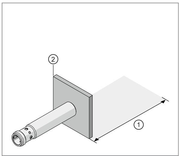
Fig. 7: MBA
1: Measuring range
2: Initial value of the measuring range (MBA)
Mean value of the mesauring range (MBM)
▶ Position the object to be detected at the mean value of the measuring range (distance value → IODD).
▶ Execute command: [MBM].

Fig. 8: MBM
1: Measuring range
2: Mean value of the mesauring range (MBM)
Final value of the measuring range (MBE)
▶ Position the object to be detected at the mean value of the measuring range (distance value → IODD).
▶ Execute command: [MBE].

Fig. 9: MBE
1: Measuring range
2: Final value of the measuring range (MBE)
For final calibration:
▶ Execute command: [Execute 3 Point calibration].
The sequence of the three calibrations is not relevant.
7.1.1.3 Factory calibration
This calibration is suitable for large aluminium targets.
▶ Call up [Parameter] > [Application configuration] > [Linearity adjustment].
▶ Set [Factory settings].
▶ Execute command: [Execute factory calibration.]
8 Maintenance, repair and disposal
▶ It is not possible to repair the unit.
▶ After use, dispose of the unit in an environmentally friendly way in accordance with the applicable national regulations.
▶ In case of return shipment, ensure that the unit is free from soiling, especially from dangerous and toxic substances.
9 Factory settings
| Parameter | Factory setting |
| P-n | 0 (PnP) |
| SSC1.1 Param. SP1 | 81% if MBE |
| SSC1.1 Config. Logic | High active |
| SSC1.1 Config. Mode | Single point |
| SSC1.1 Config. Hyst | 7% |
| SSC1.1 Switch-On delay | 0 s |
| SSC1.1 Switch-Off delay | 0 s |
| SSC1.2 Param. SP1 | 50% of MBE |
| SSC1.2 Config. Logic | High active |
| SSC1.2 Config. Mode | Single point |
| SSC1.2 Config. Hyst | 7% |
| SSC1.2 Switch-On delay | 0 s |
| SSC1.2 Switch-Off delay | 0 s |
| Factory calibration | active |
| dAP | 0 |
Glossary
Aktive Schaltzone / Aktive Zone
Area above the sensing face in which the sensor reacts to the approach of the target.
Ausgangsfunktion
Normally open: Object within the active zone - output stage supplied with current. Normally closed: Object within the active zone - output stage not supplied with current. Programmable: Choice between normally closed or normally open. Positive switching: Positive output signal (to L-). Negative switching: Negative output signal (to L+).
Current consumption
The current for self-supply of DC appliances without load.
Hysteresis
Difference between switch-on and switch-off point.
Operating voltage
Voltage range in which the sensor operates reliably. A stabilised and smoothed direct voltage should be used! Take into account the residual ripple.
Power-on delay time
The time the sensor needs to be ready for operation after application of the operating voltage (in the millisecond range).
Product standard
IEC 60947-5-2
Standard target
Square-shaped steel plate (e.g. S235JR) of a thickness of 1 mm with a side length equal to the diameter of the sensing face or 3 x Sn, depending on which value is the highest.
Switch point drift
The shifting of the switch point due to changes in the ambient temperature.
Switching frequency
Damping with standard target (a x a) at half Sn. The ratio of damped to undamped (tooth to gap) is 2:1.
- 1 PRELIMINARY NOTE
- 1.1 SYMBOLS USED
- 2 SAFETY INSTRUCTIONS
- 3 INTENDED USE
- 4 FUNCTION
- 4.1 SWITCHING FUNCTION WITH SWITCH POINT
- SINGLE POINT MODE
- TWO POINT MODE
- WINDOW MODE
- CONDITIONS FOR SWITCHING POINTS
- 4.2 IO-LINK
- 5 INSTALLATION
- 5.1 INSTALLATION CONDITIONS IFP20X
- 5.2 INSTALLATION CONDITIONS IGP20X
- 5.3 INSTALLATION CONDITIONS IIP20X
- 6 ELECTRICAL CONNECTION
- 7 PARAMETER SETTING
- 7.1 ADJUSTABLE PARAMETERS
- 7.1.1 APPLICATION CONFIGURATION
- 7.1.1.1 1-POINT CALIBRATION
- 7.1.1.2 3-POINT CALIBRATION
- INITIAL VALUE OF THE MEASURING RANGE (MBA)
- MEAN VALUE OF THE MESAURING RANGE (MBM)
- FINAL VALUE OF THE MEASURING RANGE (MBE)
- FOR FINAL CALIBRATION
- 7.1.1.3 FACTORY CALIBRATION
- 8 MAINTENANCE, REPAIR AND DISPOSAL
- GLOSSARY
- AKTIVE SCHALTZONE / AKTIVE ZONE
- AUSGANGSFUNKTION
- CURRENT CONSUMPTION
- HYSTERESIS
- OPERATING VOLTAGE
- POWER-ON DELAY TIME
- PRODUCT STANDARD
- STANDARD TARGET
- SWITCH POINT DRIFT
- SWITCHING FREQUENCY
Brand : IFM
Model : IFP201
Category : Detector