ZIBTS350 - Breaker Zipper - Free user manual and instructions
Find the device manual for free ZIBTS350 Zipper in PDF.

| Product type | Breaker (concrete saw) |
| Brand | Zipper |
| Model | ZIBTS350 |
| Engine | 1 cylinder, 2-stroke, air-cooled, 65 cm³, 3 kW |
| Fuel supply | Mixture gasoline/oil 40:1, tank 1.5 L |
| Blade diameter | 300 to 350 mm |
| Blade bore | 20 / 25.4 mm |
| Max cutting depth | 115 mm (350 mm blade) |
| Rotation speed | 4850 rpm |
| Starting | By cable |
| Sound level | 114 dB(A) |
| Net weight | 13 kg |
| Dimensions (L × W × H) | 750 × 420 × 320 mm |
| Main functions | Cutting concrete and asphalt; water cooling; adjustable blade guard |
| Safety | ON/OFF switch, throttle lock, blade guard, engine stop |
| Maintenance | Cleanable air filter, spark plug (0.7-0.8 mm gap), V-belt tension, bearing lubrication |
| Cleaning | Water or mild detergent; do not use solvents |
| Spare parts | Available at dealer or Zipper; use original parts |
| Warranty | 2 years (DIY use) / 1 year (professional use) |
| Included accessories | Blade mounting wrench, belt guard |
Frequently Asked Questions - ZIBTS350 Zipper
User questions about ZIBTS350 Zipper
0 question about this device. Answer the ones you know or ask your own.
Ask a new question about this device
Download the instructions for your Breaker in PDF format for free! Find your manual ZIBTS350 - Zipper and take your electronic device back in hand. On this page are published all the documents necessary for the use of your device. ZIBTS350 by Zipper.
USER MANUAL ZIBTS350 Zipper
SRB UPUTSTVO ZA UPOTRBU
CONCRETE CUTTER
natural_image
Green and silver industrial cutting tool with a white base, showing blade and cutting edge (no text or symbols visible)ZI-BTS350
EAN: 9120039230733
CE

1 INHALT / INDEX
11.1 Main Components and Controls 26
11.2 Technical Data.... 27
12 SAFETY 27
12.1 Intended Use.... 27
12.2 Safety 27
12.3 Specific risks and hazards when working with concrete cutter 29
13 GETTING STARTED 31
13.1 During the initial commissioning 31
13.1.1 Fitting the cutting blade 31
13.1.2 Protection cover set.... 31
13.1.3 Adjust V-belt tension: 32
13.1.4 Refuelling.... 32
14 OPERATION 33
14.1 Engine Start....33
14.1.1 Cold start: 33
14.1.2 Warm start.... 34
14.1.3 Switch off.... 34
14.1.4 Water supply 34
15 MAINTENANCE 35
15.1 Maintenance activities....35
15.2 Spark plug (every 50h) ...... 35
15.3 Cleaning 35
15.4 Storage....35
15.5 Disposal....36
16 TROUBLESHOOTING 36
17 PREFACIO (ES) 37
18 CARACTERÍSTICAS TÉCNICAS 38
18.1 Controles y componentes .... 38
18.2 Datos técnicos 39
19 SEGURIDAD 39
EN EC-CONFORM - This product complies with the EC-directives.
EN READ THE MANUAL! Read the user and maintenance manual carefully and get familiar with the controls in order to use the machine correctly and to avoid injuries and machine defects.
EN ATTENTION! Ignoring the safety signs and warnings applied on the machine as well as ignoring the security and operating instructions can cause serious injuries are even lead to death.
EN Protective clothing!
EN Solid Objects can be thrown away!
EN Warning about cut injuries!
EN Keep safe distance!
EN Only trained staff!
EN Stop before any break and engine maintenance!
text_image
Technical diagram of a mechanical device with numbered components for identification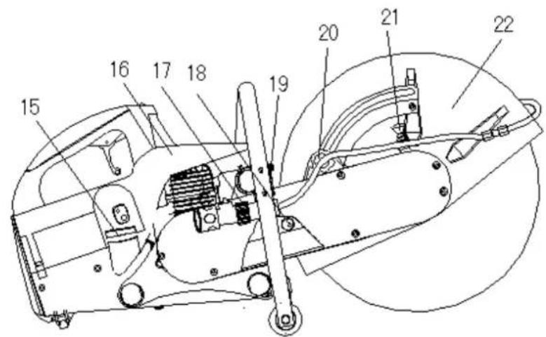
text_image
Technical diagram of a mechanical device with numbered components for identificationZI-BTS350
natural_image
Vertical sequence of blue circular icons representing safety and engineering symbols (no text or labels)text_image
Technical diagram of a mechanical device with numbered components and directional arrows indicating motion or flow.
text_image
Drehknopf 1text_image
Technical diagram of a mechanical device with numbered components and labeled partsnatural_image
Technical line drawing of a mechanical assembly with no visible text or symbols
text_image
EIN AUS Schalter 5 3 4 2natural_image
Illustration of a spark plug with a handle and screw base (no text or symbols)(Picture 18)
text_image
0.7-0.8(Picture 19)
8.3 Reinigung
HIN WEI S
This manual contains important information and advice for the correct and safe use and maintenance of the concrete cutter ZI-BTS350.
Following the usual commercial name of the device (see cover) is substituted in this manual with the name "machine".
The manual is part of the machine and may not be stored separately. Read it profoundly before first use of the machine and keep it for later reference. When the machine is handed to other persons always put the manual to the machine.
Please follow the security instructions!
Please read the entire manual, to prevent misunderstandings, machine damage or even injuries!

Due to continuous development of our products illustrations, pictures might differ slightly.
If you however find errors in this manual, please inform us.
Technical changes excepted!
Copyright law
© 2015
This manual is protected by copyright law – all rights reserved. Especially the reprinting as well as the translation and depiction of pictures will be prosecuted by law. Court of jurisdiction is the Landesgericht Linz or the competent court for 4707 Schlüsslberg, AUSTRIA.
Customer Support
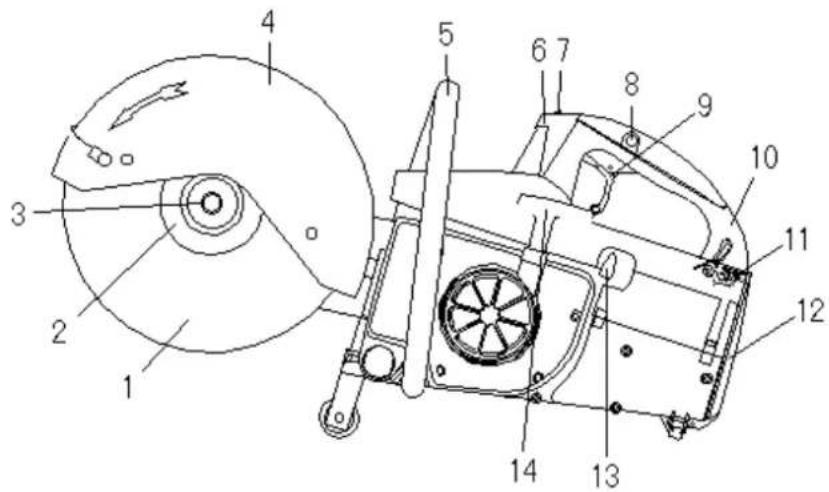
11.1 Main Components and Controls
text_image
Technical diagram of a mechanical device with numbered components and a magnified view of the front view.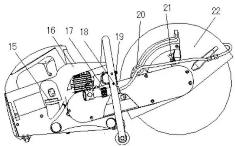
text_image
Technical diagram of a mechanical device with numbered components for identification| ZI-BTS350 | |||
| 1 | Cutting disc | 12 | Air filter |
| 2 | Flange | 13 | Choke lever |
| 3 | Hexagon screw | 14 | reversing starter |
| 4 | Cover | 15 | Fuel tank |
| 5 | Front bracket | 16 | decompression |
| 6 | Spark plug | 17 | Water supply |
| 7 | ON OFF Switch | 18 | V-belt tension |
| 8 | Throttle lock button | 19 | Sound absorber |
| 9 | Throttle | 20 | Knob protective cover |
| 10 | Handle back | 21 | Locking blade |
| 11 | Switch air filter | 22 | Protective cover |
11.2 Technical Data
| ZI-BTS350 | ||
| Motor / Drive | Spec. | 2-stroke, 1-cylinder, air-cooled |
| Displacement | cm^3 | 65 |
| power | kW | 3 |
| Fuel / oil ratio | 40:1 | |
| Fuel tank | Liter | 1,5 |
| ∅ Cutting disc | mm | 300-350 |
| ∅ bore Cutting disc | mm | 20 / 25,4 |
| Max. depth of cut | mm | 92 / 115 |
| Max. speed whell | U/min | 4850 |
| Starter | Spec. | cable |
| Sound power level L_WA | dB(A) | 114 |
| Weight | kg | 13 |
| Dimensions (LxWxH) | mm | 750x420x320 |
12 SAFETY
12.1 Intended Use
The ZIPPER ZI-BTS350 is approved for the following stated activities in compliance with the safety instructions described in this operating and maintenance instructions:
Asphalt and concrete cutting in compliance with all technical limits and all safety regulations.
The improper use or failure to comply with the provisions and instructions detailed in this manual will void all claims for damages against the ZIPPER GmbH result.
Unauthorized modifications and manipulations of the machine also immediately invalidate all warranty and damage claims.
12.2 Safety
Warning signs and / or labels on the machine that are illegible or have been removed are to be replaced immediately!
The most important factor for adequate security at work is common sense. Care and good judgment are the best protection against injury. This list of general safety information does not purport to include all possible sources of danger, but we have tried to highlight some of the important details. Individuals should look for caution, warning and danger signs that are marked on the device and displayed at work and read the safety, understand and heed.

During refueling the fire, naked flame and smoking prohibited.
Refuel with the engine running or when engine parts are still hot, is strictly prohibited.
Refuel only outdoors or in well-ventilated areas.
Wipe off spilled fuel immediately.
Fuel is highly flammable!
With fatigue, lack of concentration or under the influence of medicines, alcohol or drugs that work on the machine is prohibited!
Before each use, check machine in perfect condition! Oil level, blade condition, tightness screws etc ...
The regular maintenance and inspection is safety critical.

The machine may only be operated by qualified personnel enrolled. Unauthorized persons, especially children, and people are not trained to keep away from the machine! Operation of the machine just over 18 years.


If you work on the machine, you do not wear loose jewelry, loose clothing, ties, long, loose hair, etc ...
Loose objects can become entangled in moving parts of the machine and cause injury!

natural_image
Four blue circular icons representing safety symbols: tool, hand, foot, and person (no text or numbers)When working on the machine zertifizerte appropriate protective equipment (gloves, work shoes with steel inserts, safety glasses, hearing protection, ...) wear!
Engine emissions contain toxic gases, which have a negative impact on personal health. Therefore, they work with the machine in a well ventilated area or outdoors!
NEVER touch the carburetor, spark plug, air filter. Motor unit during and immediately after the operation! Risk of burns!
Allow the engine to cool before adding fuel perform maintenance etc. ...

The running machine should never be left unattended! Turn off the machine before leaving the work area and wait until the engine is at a standstill!
12.3 Specific risks and hazards when working with concrete cutter
Concrete cutters are heavy units and should be positioned by two people with appropriate force, the machine-mounted lifting handles are to be used, furthermore, make sure that a proper lifting techniques.
Bruises
Minimize the risk of crushing her foot by wearing work boots with steel toes.
Make sure that the machine and the operator on level ground are both stable when setting up and the machine will not tip over during operation, slipping or falling.
Injury by diamond saw blade
Contact with the rotating diamond saw blade will result in serious injury.
The machine is to maneuver with the mounting brackets, with secure stand BEHIND the machine.
Within 15m No 2 Person.
Flying asphalt concrete fragments
NEVER remove splash guard lip. Damaged immediately renew. Use break-resistant certified goggles.
Hazards of the work environment
Make sure that the walls of a trench are stable and not collapse because of the vibration.
Make sure that the area to stomping does not "live" electrical wires, gas pipes, or water pipes, which can be damaged by vibration.
Be careful when working near unprotected wells or pits. The operation of the machine is its own discretion and at your own risk.
Risk of burns
Touching the carburetor, the engine, the spark plug and other heatable machine components can cause serious burns, after prolonged continuous operation.
Fire and Explosion Hazards
Fuel is highly flammable and explosive under certain conditions.
NEVER use fuel or engine oil while the machine is in operation or still hot.
Refueled places where fuel is stored, not smoke or allow open flames or sparks.
Do not overfill the fuel tank and avoid the spillage of gasoline during refueling. If any fuel is spilled, make sure that this area is dry / cleaned before starting the engine.
Refuel only with the filter.
Make sure that the fuel tank cap is tightly closed after refueling again safely.
Chemical hazards
Never operate or refuel a gasoline or diesel engine in a closed area without adequate ventilation
Carbon monoxide emissions from the internal combustion engine of the drive units can cause damage to health by inhalation in confined spaces and death. Therefore, the engine take in a well ventilated area or outdoors in operation.
Noise hazards
Working with the concrete release cutter without hearing protection certified to cause hearing damage and temporary or permanent hearing loss. Wear a certified health and safety regulations after hearing protection to limit noise pollution.
Special protective clothing
Apart from the general safety instructions listed in the guidelines for the wearing of protective clothing special protective clothing and safety shoes must be worn with steel inserts.
Maintenance
Make sure that repairs to the motor and the machine are carried out by qualified personnel.
Make sure that the red engine switch is in the OFF position and the ignition wire is disconnected from the spark plug before you remove the protection, perform service, adjust belt or make adjustments.
13 GETTING STARTED
On the device are only few of them serviceable components. It is not allowed to disassemble the machine. Repairs must only be performed by an expert!
Accessories: Use only recommended by your dealer or by ZIPPER Accessories!
If you have any questions or problems, contact our customer service.
13.1 During the initial commissioning
The machine is delivered pre-assembled, you only need to mount the blade and possibly the retaining bracket.
13.1.1 Fitting the cutting blade

text_image
Technical diagram of a mechanical device with numbered components and directional arrows indicating motion or flow.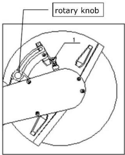
text_image
rotary knob 1ON OFF Switch to the OFF switch
• Press the lock (1) of the blade at a slight rotation of the blade to the spindle.
- With the supplied wrench, unscrew the nut (2) from the spindle.
- Remove the washer (3) and the outer flange (4).
- Place the blade on the spindle renewed. Replace the flange and the right case-washer and tighten the nut. Tightening torque 22 Nm.
The mother herself is tightening the screw in the direction of rotation.
13.1.2 Protection cover set
Use the rotary knob (1) You can change the position of guard.
Make sure that there is as little dust from the operator of the machine directed.
13.1.3 Adjust V-belt tension:
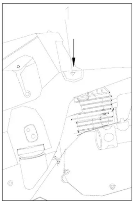
- Remove the screws (1) on the drive housing and remove the belt guard (2).
- Loosen the three screws (3) on the belt guide.
- Turn the block plug (4) set in the clockwise direction about the optimum tension of the V-belt.
- Tighten the mounting screws (3) firmly.
- Attach the belt cover with the screws (1)

text_image
Technical diagram of a mechanical assembly with numbered components and directional arrows indicating motion or movement.Adjust belt tension after 5 minutes of idling.
During the first day in operation, you should frequently check the belt tension. Belts are correctly tensioned when it does not just slip under full load. Excessive tension reduces the life of the belt.
13.1.4 Refuelling
The concrete cutting cutter is powered by a gasoline-oil mixture.
For the 2-stroke engine, you need a gasoline-oil mixture with a mixing ratio of 40:1.
When refueling sure that no foreign particles get into the tank.

During refueling the fire, naked flame and smoking prohibited.
Refuel with the engine running or when engine parts are still hot, is strictly prohibited.
Refuel only outdoors or in well-ventilated areas.
Wipe off spilled fuel immediately.
Fuel is highly flammable!
Use high-quality synthetic oil for heavy-duty two-stroke engines, if you want to make your mixture itself. Synthetic oil reduces soot and deposits on spark plug in the cylinder, the piston and the exhaust what the engine lubrication increases, and thus the life of the engine. Ge self-made mixtures are to consume within 4 weeks.
ZIPPER Maschinen recommends the use of high-quality finished mixtures specifically for heavy-duty two-stroke engines.
HINWEI S
Before each use, shake the tank properly! Otherwise, the risk of damage to the motor consists of seizures, because it is lubricated at the beginning too little.
Before each operation:
- Check the tightness of the blade, the fixing nut and all other threaded fasteners.
- Check the fuel level and refill if necessary (fuel mixture ratio 40:1)
14 OPERATION
14.1 Engine Start
Place the concrete release cutter safely on the ground. The blade must not be to the ground or other objects together.
Before the blade, no persons are allowed to stay there.
NOTE: Remove at least 3m from the refueling.
14.1.1 Cold start:
- Press the ON-OFF switch to the "ON" position
- Adjust the combi-switch (2) the corresponding position.
- At restart the combination switch (2) in to be adjusted to the "Choke" Position.
- On a warm start of the "Choke" is not used. The combi-switch remains in the Position.
- Press with your hand on the handle above the switch (3) of the throttle lever (4). Then push the throttle lever (4) up.
- Press with your thumb throttle-lock button (5) and leave at the same time the throttle lever to the lock button can lock.
natural_image
Technical line drawing of a mechanical component with no visible text or symbols
text_image
ON-OFF switch 5 3 4 2- Press the the decompression (1) button.
- Hold the front hand lever with one hand and press with your foot to the lateral pedal to the floor.
- Start Cable: Cable tighten until resistance can roll back and then forcefully put in a train. If the engine according to the third Tightening does not start, open the choke slightly.
- Falls der Motor nach dem 3. Anziehen nicht anspringt, Choke etwas öffnen.
- The combi-switch after the first engine noises flammable placed in the position.
- If the engine is running throttle lever (4) Press briefly to dislodge the lock button and the full throttle position is changed to idle.
- Leave for a few minutes without engine load.
- When a load is always at max throttle. Hold speed!
14.1.2 Warm start
- Press the ON-OFF switch to the ON position.
• Combination switch (2) in the OPEN position on the right. Do not choke on a warm start.
• Engine with pull starter start
14.1.3 Switch off
For a longer life of your engine you let the engine to idle for 3-5 minutes before turning off idle.
- ON OFF switch to OFF position switch.
NOTE:
The length of the starter pull rope is 1.15 meters. Do not pull with great force. When all the rope has been pulled, the rope is pulled with further train. In addition, it can also mean that the parts are damaged.
Once you have pulled the rope, should you let it go immediately. One should continue to hold the hand lever of the starter pull rope and lead it back down.
The rope should be straight up or down to reduce wear.
After the train of the starter pull cord you can roll it slowly.
At this time, when the gasoline engine is not started successfully, it is necessary to press the button of the decompression valve again to restart.
14.1.4 Water supply
The water connection, you can connect a water supply.
This allows you to achieve a uniform cooling of the blade and reduce the formation of dust strongly.
Operation
- Review safe working environment, safe work clothing, machine before putting on faultless and operational condition.
- Saw at Max., align top position, fold down section markers (linkage with red roller) to cut line. Align the saw blade to cut line.
- gate valve at the bottom of the water tank open.
- Start the engine
- blade wind down slowly deepen the cut until the desired depth of cut is reached.
• Cut only as fast as it allows the material. If the blade lifts the feed, you slow down the feed! - If desired cutting depth of more than 90mm, this should be achieved through two steps.
- The proper sense of the proper feed speed is important. Please slide the machine fast enough that the blade can work into the material, but once they realize that the speed decreases, reduce the feed.
- No lateral pressure on the blade.
- Can not operate without blade guard mounted!
- Do not force the blade into the material. Let the wheel going into the material alone.
- Do not perform long continuous cuts.
- No Dry cutting saw blades are suitable for wet cutting.
- No curves intersect. Not inclined to fix blade material.
15 MAINTENANCE
15.1 Maintenance activities
- Check the engine oil level before each use
- Check the belt tension and adjust as required
- Lubricate the bearings of the diamond saw blade axis daily
- Before each use, the blade is in good condition and tight fit
- Before each use the air filter is clean.
-
Before each use screw connections for tightness
• Air filter (every 100 hours) -
Remove the air filter.
- Clean it in a solution.
- Drops of engine oil on the air filter.
- Waste engine oil to remove from the air filter by wring it out.
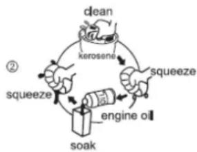
flowchart
graph TD
    A["clean"] --> B["kerosene"]
    B --> C["squeeze"]
    C --> D["engine oil"]
    D --> E["soak"]
    E --> F["squeeze"]
    F --> G["②"]
CAUTION: NEVER WITHOUT ENGINE AIR FILTER OR MAINTAINED AIR FILTER WITH NOT OPERATE
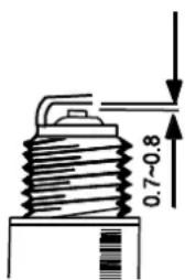
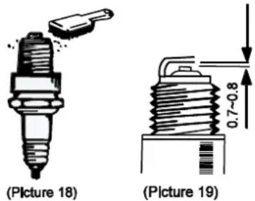
15.2 Spark plug (every 50h)
- Remove the spark plug contact.
- Remove any debris with a brush.
- Inspect the spark plug for discoloration.
- Check the contact gap. Standard: 0.7 0.8mm
text_image
(Picture 18) (Picture 19)15.3 Cleaning
NOTE
Cleaning: The use of paint thinners, gasoline, corrosive chemicals or abrasive cleaners will result in damage to the surface!
Therefore:
When cleaning, use only mild detergent
15.4 Storage
If the machine more than a month is not used, please follow these instructions:
- Entire remove fuel from the tank, fuel cock and carburetor.
• Water from the tap and remove line (this is to do in cold weather after each use) - Remove spark plug, pour about 1 tablespoon of engine oil into spark plug hole
• Engine switch to the OFF - Operate starter rope several times
- Spark plug insert
- Generator in a dry, well ventilated place, cover.
15.5 Disposal
Do not dispose of your waste in the ZI-BTS350. Contact your local authorities for information regarding the available disposal options. Improper disposal can lead to contamination of soil, ground water soil seepage of hazardous and noxious substances, and thus reach finally through contaminated water into your food supply and your health. Replace your old unit with a new one at your local dealer, is obligated to take back your old equipment free of charge for the purpose of proper disposal.

16 TROUBLESHOOTING
| Trouble | Possible Cause | Solution |
| Engine will not start | ON OFF switch to OFFFuel filter cloggedGreat power tank emptySpark plug is defective or looseSpark plug gap set wrong | Switch in the On positionFuel filter changeFill the fuel tankClean or replace spark plugCheck the correct setting |
| Engine stops after starting | Idle speed too lowClogged fuel filterThe fuel tank is empty | Adjust idle speedChange the fuel filteradd fuel |
| Less engine power | Dirty air filter | Clean or replace air filter |
| Bade does not run | V-belt is defectivedefective clutch | Change beltsmachine repair |
| Blade runs bad | cutting wheel shaft | Check ball bearings, shaft, flange and nut.Replace if defective |
17 PREFACIO (ES)
Estimado Cliente,
text_image
Technical diagram of a mechanical device with numbered components for identification
text_image
Technical diagram of a mechanical device with numbered components for identificationZI-BTS350
natural_image
Blue circular icons representing safety symbols including hand gesture, walking, boot, hand tools, and tool (no text or labels)text_image
Technical diagram of a mechanical device with numbered components labeled 2 through 5
text_image
Perilla 1text_image
Technical diagram of a mechanical assembly with numbered parts labeled 1 to 420.1.4 Repostaje
natural_image
Technical line drawing of a mechanical assembly with no visible text or symbols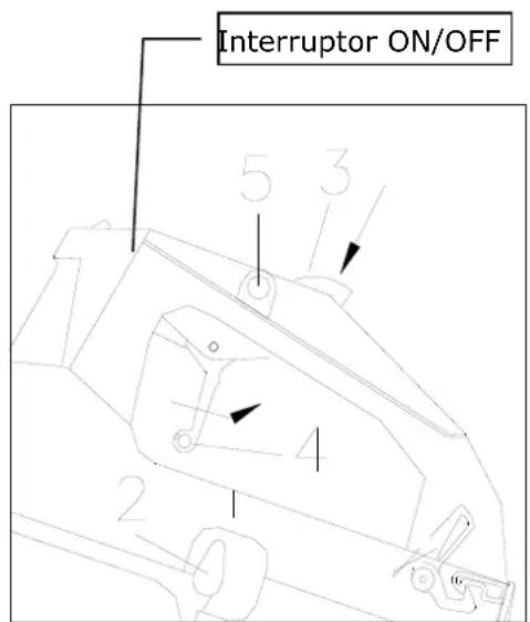
text_image
Interruptor ON/OFF 5 3 4 2- Pulse
natural_image
Symbol of a trash bin crossed out by two diagonal lines (no text or numbers present)text_image
Technical diagram of a mechanical device with numbered components for identification
text_image
Technical diagram of a mechanical device with numbered components for identificationZI-BTS350
natural_image
Blue circular icons representing various safety and engineering symbols (no text or labels)text_image
Technical diagram of a mechanical device with numbered components labeled 2 through 5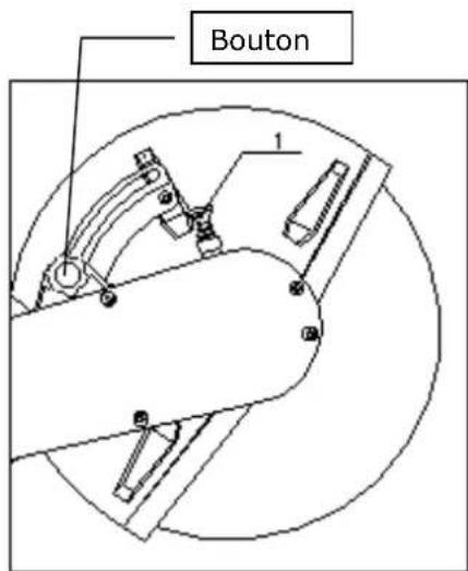
text_image
Bouton 1text_image
Technical diagram of a mechanical device with numbered parts labeled 1 to 427.1.4 Remplissage
natural_image
Technical line drawing of a mechanical assembly with no visible text or symbols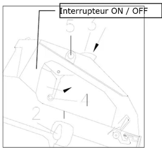
text_image
Symbol of a trash bin crossed out by a diagonal line, indicating no waste or disposal.30 DEPANNAGE
text_image
Technical diagram of a mechanical device with numbered components for identification
text_image
Technical diagram of a mechanical device with numbered components for identificationZI-BTS350
natural_image
Blue circular icons representing various safety and equipment symbols (no text or labels)text_image
Technical diagram of a mechanical device with numbered components and directional arrows indicating motion or flow.
text_image
Růžice 1text_image
Technical diagram of a mechanical assembly with numbered components labeled 1 to 4natural_image
Technical line drawing of a mechanical component with no visible text or symbols
text_image
EIN AUS vypínač 5 3 4 2text_image
Technical diagram of a mechanical device with numbered components and an inset view showing a circular component.
text_image
Technical diagram of a mechanical device with numbered components for identificationnatural_image
Vertical sequence of blue circular icons representing various safety and hazard symbols (no text or labels)text_image
Technical diagram of a mechanical device with numbered components and directional arrows indicating motion or flow.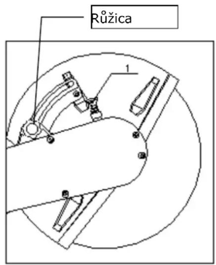
text_image
Růžica 1Vypínač stroja nastavte do polohy AUS.
text_image
Technical diagram of a mechanical assembly with numbered components labeled 1 to 4natural_image
Technical line drawing of mechanical components with no visible text or symbols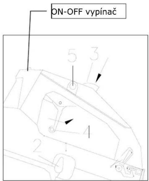
natural_image
Symbol of a trash bin crossed out by two diagonal lines (no text or numbers present)
44 ODSTRÁNENIE ZÁVAD
text_image
Technical diagram of a mechanical device with numbered components for identification
text_image
Technical diagram of a mechanical device with numbered components for identificationnatural_image
Vertical sequence of blue circular icons representing safety symbols (no text or numbers)text_image
Technical diagram of a mechanical device with numbered components and directional arrows indicating motion or flow.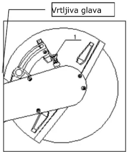
text_image
Vrtljiva glava 1Stikalo za vklop in izklop naj bo v položaju IZKLOP.
- Pritisnite na zaporo (1) rezalne plošče, tako da lahno obrnete rezalno ploščo v vreteno.
• S priloženim viličnim ključem odvijte matico (2) iz vretena. - Snemite podložko (3) in zunanjo prirobnico (4).
- Postavite novo rezalno ploščo na vreteno. Prirobnico in podložko pravilno položite nazaj in ponovno privijte matico. Pritezni vrtilni moment 22 Nm.
text_image
Technical diagram of a mechanical assembly with numbered components labeled 1 to 4natural_image
Technical line drawing of a mechanical component with no visible text or symbols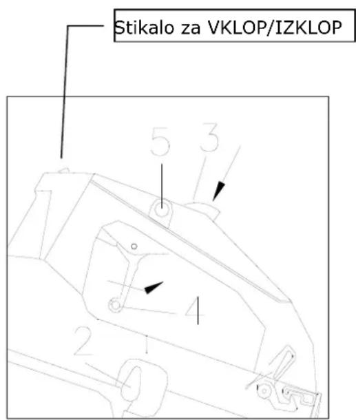
text_image
Stikalo za VKLOP/IZKLOP 5 3 4 2natural_image
Symbol of a trash bin crossed with no text or numbers, representing waste sorting or disposal (no text present)51 ODPRAVLJANJE NAPAK
text_image
Technical diagram of a mechanical device with numbered components and an inset view showing a circular component.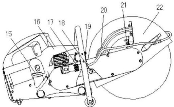
text_image
Technical diagram of a mechanical device with numbered components for identification| ZI-BTS350 | |||
| 1 | Rezna ploča | 12 | Filtar za zrak |
| 2 | Prirubnica | 13 | Ručica "čoka" |
| 3 | 6-kutni vijak | 14 | Pokretač s užetom |
| 4 | Zaštitni poklopac | 15 | Spremnik goriva |
| 5 | Prednji stremen za držanje | 16 | Dekompresijski ventil |
| 6 | Utikač za svjećicu | 17 | Priključak za vodu |
| 7 | Prekidač za uključivanje/isključivanje | 18 | Zatezanje V-remena |
| 8 | Tipka za zaključavanje ručice gasa | 19 | Prigušivač buke |
| 9 | Ručica gasa | 20 | Okretna tipka za zaštitni poklopac |
| 10 | Stražnja drška | 21 | Mehanizam za zaključavanje rezne ploče |
| 11 | Sklopka filtra za zrak | 22 | Zaštitni poklopac |
53.2 Tehnički podaci
| ZI-BTS350 | ||
| Motor / pogon | Spec. | 2-taktni motor s 1 cilindrom, hlađen zrakom |
| Zapremina | cm^3 | 65 |
| Snaga motora | kW | 3 |
| Omjer gorivo / ulje | 40:1 | |
| Spremnik goriva | litara | 1,5 |
| ∅ rezne ploče | mm | 300-350 |
| ∅ provrta rezne ploče | mm | 20 / 25,4 |
| maks. dubina reza | mm | 92 / 115 |
| maks. broj okretaja ploče | o/min | 4850 |
| Pokretač | Spec. | Potezno uže |
| Razina zvučne snage L_WA | dB(A) | 114 |
| Težina | kg | 13 |
| Dimenzije (DxŠxV) | mm | 750x420x320 |
54 SIGURNOST
natural_image
Vertical sequence of blue circular icons representing various safety and equipment symbols (no text or labels)Za vrijeme radova na stroju nosite prikladnu certificiranu zaštitnu opremu(zaštitne rukavice, radnu obuću s čeličnim umecima, zaštitne naočale, zaštitu za uši, ...)!
text_image
Technical diagram of a mechanical device with numbered components and directional arrows indicating motion or flow.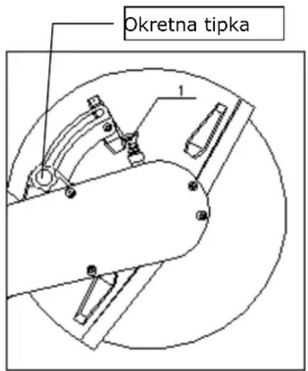
text_image
Okretna tipka 1text_image
Technical diagram of a mechanical assembly with numbered components labeled 1 to 4natural_image
Technical line drawing of mechanical components with no visible text or symbols
text_image
(Picture 19)(Picture 18)
57.3 Čišćenje
NAPOMENA
Čišćenje: Upotreba razrjeđivača za boju, benzina, agresivnih kemikalija ili abrazivnih sredstava dovodi do materijalnih šteta na površinama!
natural_image
Symbol of a trash bin crossed with no text or labels, accompanied by a black rectangular block below (no readable text or symbols)58 UKLANJANJE POGREŠAKA
text_image
Technical diagram of a mechanical device with numbered components, including a close-up view and detailed cross-sections.
text_image
Technical diagram of a mechanical device with numbered components for identification| ZI-BTS350 | |||
| 1 | Rezna ploča | 12 | Filter za vazduh |
| 2 | Prirubnica | 13 | Ručica "čoka" |
| 3 | 6-ugaoni vijak | 14 | Pokretač s užetom |
| 4 | Zaštitni poklopac | 15 | Rezervoar goriva goriva |
| 5 | Prednji stremen za držanje | 16 | Dekompresioni ventil |
| 6 | Utikač za svećicu | 17 | Priključak za vodu |
| 7 | Prekidač za uključivanje/isključivanje | 18 | Zatezanje V-kaiša |
| 8 | Tipka za zaključavanje ručice gasa | 19 | Prigušivač buke |
| 9 | Ručica gasa | 20 | Okretna dirka za zaštitni poklopac |
| 10 | Stražnja drška | 21 | Mehanizam za zaključavanje rezne ploče |
| 11 | Sklopka filtera za vazduh | 22 | Zaštitni poklopac |
text_image
Vertical sequence of blue circular icons with white safety symbols, likely representing a safety or hazard warning.text_image
Technical diagram of a mechanical device with numbered components and directional arrows indicating motion or flow.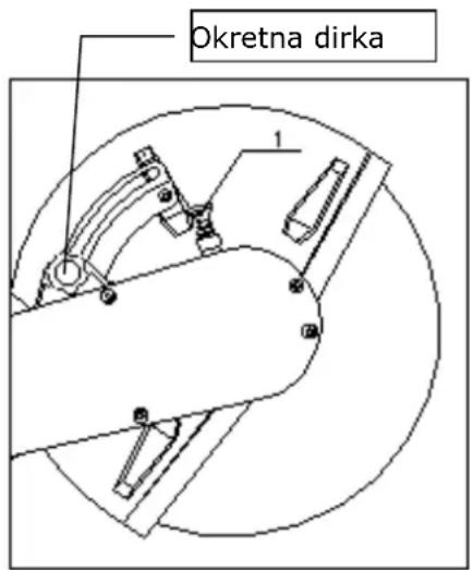
text_image
Okretna dirka 1text_image
Technical diagram of a mechanical assembly with numbered components labeled 1 to 4Zategnutost kaiša podesite nakon 5-minutnog praznog hoda. Toekom prvog dana rada često trebate proveravati zategnutost remena. Remeni su ispravno zategnuti tek kad pod punim opterećenjem ne klize. Prejako zatezanje smanjuje životni vek kaiša.
62.1.4 Sipanje goriva
natural_image
Technical line drawing of a mechanical component with no visible text or symbols
text_image
(Picture 19)(Picture 18)
64.3 Čišćenje
NAPOMENA
Čišćenje: Upotreba razređivača za boju, benzina, agresivnih hemikalija ili abrazivnih sredstava dovodi do materijalnih šteta na površinama!
Zato, prilikom čišćenja koristite samo blaga sredstva za čišćenje!
64.4 Skladištenje
With original ZIPPER spare parts you use parts that are attuned to each other shorten the installation time and elongate your machines lifespan.
IMP OR TAN T
The installation of other than original spare parts voids the warranty!
So you always have to use original spare parts
When you place a spare parts order please use the service formular you can find in the last chapter of this manual. Always take a note of the machine type, spare parts number and partname. We recommend to copy the spare parts diagram and mark the spare part you need.
You find the order address in the preface of this operation manual.
text_image
Technical diagram of a mechanical assembly with numbered components for identificationtext_image
Exploded view diagram of a mechanical assembly with numbered components for identificationtext_image
Exploded view diagram of a mechanical assembly with numbered parts for identificationtext_image
Exploded view diagram of a mechanical assembly with numbered parts for identificationtext_image
Exploded view diagram of a mechanical assembly with numbered components for identificationtext_image
Technical diagram of a mechanical assembly with numbered components for identificationtext_image
Exploded view diagram of a device assembly with numbered parts for identificationtext_image
Exploded view diagram of a device with numbered parts for identificationtext_image
Technical diagram of a mechanical device with numbered components for identificationHereby we declare that the above mentioned machines meet the essential safety and health requirements of the above stated EC directives. Any manipulation or change of the machine not being explicitly authorized by us in advance renders this document null and void.
Company ZIPPER Maschinen GmbH grants for mechanical and electrical components a warranty period of 2 years for amateur use; and warranty period of 1 year for professional use, starting with the purchase of the final consumer. In case of defects during this period, which are not excluded by paragraph 3, ZIPPER will repair or replace the machine at its own discretion.
2.) Report:
In order to check the legitimacy of warranty claims, the final consumer must contact his dealer. The dealer has to report in written form the occurred defect to ZIPPER. If the warranty claim is legitimate, ZIPPER will pick up the defective machine from the dealer. Returned shippings by dealers which have not been coordinated with ZIPPER, will not be accepted and refused.
3.) Regulations:
a) Warranty claims will only be accepted, when a copy of the original invoice or cash voucher from the trading partner of ZIPPER is enclosed to the machine. The warranty claim expires if the accessories belonging to the machine are missing.
b) The warranty does not include free checking, maintenance, inspection or service works on the machine. Defects due to incorrect usage of the final consumer or his dealer will not be accepted as warranty claims either. Some examples: usage of wrong fuel, frost damages in water tanks, leaving fuel in the tank during the winter, etc.
c) Defects on wear parts are excluded, e.g. carbon brushes, collection bags, knives, cylinders, cutting blades, clutches, sealings, wheels, saw blades, splitting crosses, riving knives, riving knife extensions, hydraulic oils, oil/air/fuel filters, chains, spark plugs, sliding blocks, etc.
d) Also excluded are damages on the machine caused by incorrect or inappropriate usage, if it was used for a purpose which the machine is not supposed to, ignoring the user manual, force majeure, repairs or technical manipulations by not authorized workshops or by the customer himself, usage of non-original ZIPPER spare parts or accessories.
e) After inspection by our qualified personnel, resulted costs (like freight charges) and expenses for not legitimated warranty claims will be charged to the final customer or dealer.
f) In case of defective machines outside the warranty period, we will only repair after advance payment or dealer's invoice according to the cost estimate (incl. freight costs) of ZIPPER.
g) Warranty claims can only be granted for customers of an authorized ZIPPER dealer who directly purchased the machine from ZIPPER. These claims are not transferable in case of multiple sales of the machine.
4.) Claims for compensation and other liabilities:
The liability of company ZIPPER is limited to the value of goods in all cases. Claims for compensation because of poor performance, lacks, damages or loss of earnings due to defects during the warranty period will not be accepted. ZIPPER insists on its right to subsequent improvement of the machine.
Product experience form
We observe the quality of our delivered products in the frame of a Quality Management policy.
Your opinion is essential for further product development and product choice. Please let us know about your:
- Impressions and suggestions for improvement.
- experiences that may be useful for other users and for product design
- Experiences with malfunctions that occur in specific operation modes
We would like to ask you to note down your experiences and observations and send them to us via FAX, E-Mail or by post:
Please describe amongst others in the problem: What has cause the problem/defect, what was the last activity before you noticed the problem/defect? For electrical problems: Have you had checked you electric supply and the machine already by a certified electrician?
3. Bitte beachten
/ Additional information
INCOMPLETELY FILLED SERVICE FORMS CANNOT BE PROCESSED! FOR GUARANTEE CLAIMS PLEASE ADD A COPY OF YOUR ORIGINAL SALES / DELIVERY RECEIPT OTHERWISE IT CANNOT BE ACCEPTED. FOR SPARE PART ORDERS PLEASE ADD TO THIS SERVICE FORM A COPY OF THE RESPECTIVE EXPLODED DRAWING WITH THE REQUIRED SPARE PARTS BEING MARKED CLEARLY AND UNMISTAKABLE. THIS HELPS US TO IDENTIFY THE REQUIRED SPARE PARTS FASTLY AND ACCEL- LERATES THE HANDLING OF YOUR INQUIRY.