
ZIKGS210DS - Saw Zipper - Free user manual and instructions
Find the device manual for free ZIKGS210DS Zipper in PDF.

| Brand | Zipper |
| Model | ZIKGS210DS |
| Product type | Compound miter saw |
| Blade diameter | 210 mm |
| Blade bore | 30 mm |
| No-load speed | 3200 / 4500 min⁻¹ (2 speeds) |
| Supply voltage | 220-240 V ~ 50 Hz |
| Miter angle | -45° to 45° (locking positions at 0°, 15°, 22.5°, 31.6°, 45°) |
| Bevel angle | 0° to 45° left and right |
| Laser | Yes, adjustable |
| Chip collection bag | Yes (with zipper) |
| Dust extraction system | Connection possible |
| Safety devices | Blade guard, workpiece clamp, start lock, emergency stop |
| Maintenance | Regular cleaning, check and replace carbon brushes, replace blade |
| Spare parts | Available from Zipper (order online or by email) |
| Warranty | 2 years non-commercial use, 1 year commercial use |
| Intended use | Wood and materials with similar physical properties |
Frequently Asked Questions - ZIKGS210DS Zipper
User questions about ZIKGS210DS Zipper
0 question about this device. Answer the ones you know or ask your own.
Ask a new question about this device
Download the instructions for your Saw in PDF format for free! Find your manual ZIKGS210DS - Zipper and take your electronic device back in hand. On this page are published all the documents necessary for the use of your device. ZIKGS210DS by Zipper.
USER MANUAL ZIKGS210DS Zipper
natural_image
Product photo of a green and black cutting machine with a blade, no visible text or symbols1 INHALT / INDEX
1 INHALT/INDEX 2
2 SICHERHEITSZEICHEN / SAFETY SIGNS / SYMBOLES DE SÉCURITÉ....5
12.1 Intended use of the machine....29
12.1.1 Technical restrictions....29
12.1.2 Prohibited applications / Dangerous misuse....29
12.2 User Requirements 29
12.3 Safety devices 30
12.4 General safety instructions....30
12.5 Electrical safety 31
12.6 Special safety instructions for this machine 31
12.7 Hazard warnings....32
12.7.1 Residual risks....32
12.7.2 Hazardous situations....32
13 TRANSPORT....33
Locking / unlocking the machine head....33
14 ASSEMBLY....34
14.1 Preparation....34
14.1.1 Checking delivery content....34
14.1.2 Requirements for the installation site 34
14.2 Assemble 34
14.3 Electrical connection....35
14.4 Settings....36
14.4.1 Fine adjustment fence 36
14.4.2 Fine adjustment of the angular position 90^ (by means of stop angle)....37
14.4.3 Fine adjustment of the angular position 45^ (by means of stop angle)....37
15 OPERATION....38
15.1 Initial check before start....38
15.2 Operation....38
15.2.1 Setting the angular position of the worktable 38
15.2.2 Setting the angular position of the machine head....39
15.23 Setting the fences....39
15.24 Setting cutting depth / cutting depth limiting 39
15.2.5 Connection to a dust collection system 40
15.2.6 Switch machine ON-OFF 40
15.2.7 Setting the speed....40
15.2.8 Switch Laser ON-OFF 40
15.3 Operation modes....40
16.2 Maintenance....42
16.2.1 Maintenance plan....42
16.2.2 Saw blade change 42
16.23 Setting the Laser 44
16.2.4 Emptying/changing the sawdust bag....44
16.2.5 Check / change carbon brushes 44
16.2.6 Exchange table insert 44
16.3 Storage....45
16.4 Disposal 45
17 TROUBLESHOOTING 45
18 AVANT-PROPOS (FR) 46
19 SECURITE 47
19.1.1 Restrictions techniques....47
19.12 Applications interdites / Mauvaises applications dangereuses....47
23.2 Maintenance....61
23.21 Plan de maintenance....62
23.4 Élimination....64
24 RESOLUTION DE PANNE 65
25 SCHALTPLAN / WIRING DIAGRAM / SCHEMA ELECTRIQUE 65
26 ERSATZTEILE / SPARE PARTS / PIÈCES DE RECHANGE.... 66
EN READ THE MANUAL: Read the user and maintenance carefully and get familiar with the controls in order to use the machine correctly and to avoid injuries and machine defects.
| # | Beschreibung / Description | Qty. |
| 1 | Maschine inkl. Sägeblatt / machine incl. saw blade / Machine, lame de scie incl. | 1 |
| 2 | Spänefangsack / sawdust bag / Sac de collecte des copeaux | 1 |
| 3 | Inbusschlüssel 6 mm / allen key 6 mm / Clef six pans 6 mm | 1 |
| 4 | Werkstückaufleger / workpiece support / Support de pièce à usiner | 2 |
| 5 | Betriebsanleitung / user manual / Mode d'emploi | 1 |
| 6 | Niederhalter / down holder / Serre-flan | 1 |
| 7 | Sägeblätter / saw blades / Lames de scie | 2 |
3.2 Komponenten / Components / Composants

| Beschreibung / Description | Beschreibung / Description | ||
| 1 | Bediengriff / handle / Poignée de commande | 15 | Gehrungswinkelindikator / mitre angle indicator / Indicateur d'angle d'onglet |
| 2 | EIN-AUS-Schalter / ON-OFF-switch / Interrupteur MARCHE-ARRÊT | 16 | Gehrungswinkelskala / mitre angle scale / Échelle d'angle à onglet |
| 3 | Sägeblattschutz (beweglich) / saw blade guard (moveable) / Protection de la lame de scie (mobile) | 17 | Drehtisch / rotary table (moveable) / Table tournante |
| 4 | Sägeblatt / saw blade / Lame de scie | 18 | Anschlag (einstellbar) / fence (adjustable) / Butée (réglable) |
| 5 | Laser / Laser / Laser | 19 | Niederhalter / downholder / Serre-flan |
| 6 | Zeiger Neigungswinkel / pointer vertical angle / Aiguille de l'angle d'inclinaison | 20 | Zugverriegelung / drag lock / Verrouillage de traction |
| 7 | Neigungswinkelskala / vertical angle scale / Échelle d'angle d'inclinaison | 21 | Spänefangsack / sawdust bag / Sac de collecte des copeaux |
| 8 | Anschlag (abnehmbar) / fence (removable) / Butée (amovible) | 22 | Transportgriff / transport handle / Poignée de transport |
| 9 | Anschlag / fence / Butée | 23 | Laser EIN-AUS-Schalter / laser ON-OFF-switch / Commutateur marche-arrêt du laser |
| 10 | Werkstückaufleger / workpiece support / Support de pièce à usiner | 24 | Drehzahl-Wahlschalter / speed selector switch / Commutateur de sélection de la vitesse de rotation |
| 11 | Fixer Tisch / fixed table / Table fixe | 25 | Motor / motor / Moteur |
| 12 | Gehrungswinkelverriegelung / mitre lock / Verrouillage de l'équerre à onglet | 26 | Führungsschienen / guide rails / Rails de guidage |
| 13 | Kippsicherung / tilt lock / Sécurité anti basculement | 27 | Verriegelungshebel / locking lever / Levier de verrouillage |
| 14 | Tischeinlage / table insert / Plaque de platine | 28 | Verriegelungsbolzen / locking bolt / Boulon de blocage |
3.3 Technische Daten / Technical data / Données techniques
| Spezifikation / Specification | |
| Netzspannung / Voltage / Tension | 220-240V / 50Hz |
| Motorleistung / engine power / Puissance du moteur | S1: 1700WS6: 25% 2000W |
| Schutzklasse / protection class / Classe de protection | II |
| Schutzart / protection mode / Classe | IPX0 |
| Leerlaufdrehzahl / saw blade speed / Régime à vide | 3200 min ^1 (I)4500 min ^1 (II) |
| Sägeblatt / saw blade / Lame de scie | ∅ 210 x ∅ 30 x 2,6 mm (24 / 40 Z) |
| Bohrung / bore / Alésage | ∅ 30 mm |
| Sägeblatt Winkel / saw blade angle / Angle de lame de scie | -45° / O° / +45° |
| Arbeitstisch Winkel / horizontal swing / Angle de la table de travail | -47° / O° / +47° |
| Max. Schnitt / max. cut / Coupe max. | 0° × 45°(L): 38 × 310 mm(R): 20 × 310 mm |
| Max. Schnitt / max. cut / Coupe max. | 0° × 90°65 x 310 mm |
| Max. Schnitt / max. cut / Coupe max. | 45° × 45°(L): 38 × 210 mm(R): 20 × 210 mm |
| Max. Schnitt / max. cut / Coupe max. | 45°×90°65 × 210 mm |
| Werkstückmindestlänge / workpiece min. length / Longueur minimale de la pièce à usiner | 160 mm |
| Absauganschlussdurchmesser / dust collection port diameter / Diamètre du raccord d'aspiration | innerer Durchmesser / internal diameter / Diamètre intérieur: ∅ 35 mmäußerer Durchmesser / external diameter / Diamètre extérieur: ∅ 42.5 mm |
| Schall-Druckpegel LPA / sound pressure level LPA / Niveau de pression acoustique LPA | 96,5 dB(A) K: 3 dB(A) |
| Schall-Leistungspegel LWA / sound power level LWA / Niveau de puissance acoustique LWA | 109,5 dB(A) K: 3 dB(A) |
| Gewicht Brutto / weight gross / Poids brute | 12,7 kg |
| Gewicht Netto / weight net / Poids net | 9,9 kg |
| Maschinenmaße (LxBxH) / machine dimensions (LxWxH) / Dimensions de la machine (LxlxH) | Maschinenkopf obere Position 0° x 0°:730×650×360mm / Tête de machine position supérieure 0° x 0°: 730×650×360mmMaschinenkopf untere Position 0° x 0°:715×650×560mm / Tête de machine position inférieure 0° x 0°: 715×650×560mm |
| Laser | |
| Laserklasse / laser class / Laser classe 2 | |
| Norm / standard / Norme | EN 60825-1:2014 |
| Laserwellenlänge / wavelength of laser / Longueur d'onde laser | 650 nm |
| Laserleistung / laser output / Puissance du laser | ≤1 mW |
natural_image
Mechanical assembly diagram showing a cutting tool with yellow alignment lines (no text or symbols)natural_image
Close-up of a hand holding a screwdriver inserted into a mechanical component, with numbered arrows indicating parts (no text or symbols present)natural_image
Mechanical cutting machine with yellow tool and labeled component (no readable text or symbols)natural_image
Mechanical assembly diagram showing a vehicle's frame and suspension components (no text or labels visible)natural_image
Close-up of mechanical components with no visible text or symbolsnatural_image
Close-up of mechanical components with a numbered label '3' pointing to a tool (no readable text or symbols)natural_image
Mechanical assembly diagram showing a cutting machine with labeled parts (1 and 2), no readable text or symbols present.Rückseite

natural_image
Mechanical assembly diagram showing gear and motor components with numbered annotations (no readable text or symbols)natural_image
Mechanical component diagram showing a clamping mechanism with labeled parts 1 and 2 (no text or symbols beyond labels)natural_image
Close-up of a mechanical device with a close-up inset showing a component labeled 1 and 2 (no visible text or symbols on the device itself)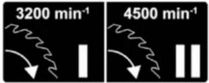
natural_image
Close-up of a mechanical device with a yellow arrow pointing to a component labeled '1' (no visible text or symbols beyond the label)natural_image
Mechanical assembly diagram showing a cutting tool and workpiece with numbered components (no text or symbols)natural_image
Mechanical assembly diagram showing a cutting tool and workpiece with numbered components (no text or symbols)natural_image
Mechanical assembly diagram showing two views of a saw cutting tool with labeled parts (no text or symbols present)natural_image
Close-up of a black industrial electrical shaver with yellow annotation arrows indicating parts of the component (no text or symbols present)natural_image
Close-up of a mechanical device with yellow annotations pointing to components (no readable text or symbols)This manual contains information and important notes for safe commissioning and handling of the ZIPPER mitre saw ZI-KGS210DS, hereinafter referred to as “machine” in this document.

This manual is part of the machine and must not be removed. Save it for later reference and if you let other people use the machine, add this manual to the machine.
Please read and note the safety instructions!
Before first use read this manual carefully. It eases the correct use of the machine and prevents misunderstanding and damages of machine.
Due to constant advancements in product design, construction, illustrations and contents may deviate slightly. If you notice any errors, please inform us.
We reserve the right to make technical changes!
Check the goods immediately after receipt and note any complaints on the consignment note when taking over the goods from the deliverer!
Transport damage must be reported to us separately to us within 24 hours.
ZIPPER MASCHINEN GmbH cannot accept any liability for transport damage that has not been reported.
Copyright
© 2022
This documentation is protected by copyright. All rights reserved! In particular, the reprint, translation and extraction of photos and illustrations will be prosecuted.
The place of jurisdiction is the regional court Linz or the court responsible for 4707 Schlüsslberg is valid.
Customer service contact
This section contains information and important notes on the safe commissioning and handling of the machine.

For your safety, read this manual carefully before commissioning. This will enable you to handle the machine safely and thus prevent misunderstandings as well as personal injury and damage to property. Pay special attention to the symbols and pictograms used on the machine as well as the safety information and danger warnings!
12.1 Intended use of the machine
The machine is intended exclusively for the following activities:
Cross-cut and mitre cutting of wood and materials with similar physical properties to wood within the specified technical limits.
NOTE

ZIPPER MASCHINEN assumes no responsibility or warranty for any other use or use beyond this and for any resulting damage to property or injury.
12.1 Technical restrictions
The machine is designed for the work under the following conditions:
Relative humidity: max. 65 %
Temperature (for operation): +5°C to +40°C
Temperature (Storage, Transport): -20^ C to +55^ C
12.1.2 Prohibited applications / Dangerous misuse
- Operating the machine without adequate physical and mental fitness.
- Operating the machine without knowledge of the manual.
• Modifying the machine design. - Operating the machine in a potentially explosive environment (machine can generate ignition sparks during operation).
• Operation of the machine in closed rooms without chip and dust extraction. - Operating the machine outside the technical limits specified in this manual.
- Removing of the safety markings attached to the machine.
- Modifying, circumventing or disabling the safety devices of the machine.
• Cutting of materials with dimensions outside the limits specified in this manual. - Use of tools which do not meet the safety requirements of the standard for machine tools for woodworking (EN847-1).
• Use of saw blades made of HSS steel.
• Use of saw blades with a lower permitted speed than the machine.
The non-intended use or the disregard of the explanations and instructions described in this manual will result in the expiration of all warranty claims and compensation claims for damages against ZIPPER MASCHINEN GmbH.
12.2 User Requirements
The machine is designed to be operated by one person. The prerequisites for operating the machine are physical and mental fitness as well as knowledge and understanding of the operating instructions. Persons
who, due to their physical, sensory or mental capabilities, inexperience or lack of knowledge, are unable to operate the machine safely must not use the machine without supervision or instruction by a responsible person.
Please note that locally applicable laws and regulations determine the minimum age of the operator and may restrict the use of this machine!
Work on electrical components or equipment may only be carried out by a qualified electrician or under the guidance and supervision of a qualified electrician.
Put on your personal protective equipment before working on the machine.
12.3 Safety devices
The machine is equipped with the following safety devices:
 | Separating protective device: blade guard |
 | Workpiece down holder and fence |
 | Locking button motor start |
12.4 General safety instructions
To avoid malfunctions, damage and health impairments when working with the machine, the following points must be observed in addition to the general rules for safe working:
- Check the machine for completeness and function before starting. Only use the machine if the separating and other non-separating protective devices required for machining have are fitted.
• Make sure that the guards are in good working order and properly maintained.
- Select a level, vibration-free surface and non-slip as the installation area.
- Anchor the machine to the ground to prevent it from lifting off or falling over when cutting.
- Ensure sufficient space around the machine!
- Ensure sufficient lighting conditions at the workplace to avoid stroboscopic effects.
- Ensure a clean working environment.
- Only use tools that are in perfect condition and free of cracks and other defects (e.g. deformations).
- Remove tool keys and other setting tools before switching on the machine.
- Keep the area around the machine free of obstacles (e.g. dust, chips, cut-off workpiece parts, etc.).
- Check the machine's connections for strength before each use.
- Never leave the running machine unattended. Switch off the machine before leaving the working area and secure it against unintentional or unauthorized restarting.
- The machine may only be operated, maintained or repaired by persons who are familiar and who have been informed about the dangers arising from this work.
- Ensure that unauthorized persons keep a safety distance from the machine and keep children away from the machine.
- Hide long hair under hair protection.
- Wear close fitting protective work clothing and suitable protective equipment (eye protection, dust mask, ear protection and work gloves only when handling tools).
• Never wear loose jewellery, loose clothing or accessories (e.g. tie, scarf).
• Always work with care and the necessary caution and never use excessive force.
- Do not remove any sections or other parts of the workpiece from the cutting area while the machine is running!
- Do not overload the machine!
- Do not work on the machine if you are tired, not concentrated or under the influence of medication, alcohol or drugs!
- Do not use the machine in areas where vapours of paints, solvents or flammable liquids represent a potential danger (danger of fire or explosion!).
- Do not smoke in the immediate vicinity of the machine (fire hazard)!
- Shut down the machine and disconnect it from the power supply, before adjustment, changeover, cleaning, maintenance or repair work, etc. Before starting work on the machine, wait until all tools or machine parts have come to a complete standstill and secure the machine against unintentional restart.
- Warning signs and/or stickers on the machine that are illegible or have been removed must be replaced immediately!
12.5 Electrical safety
• Only use suitable extension cables (cross-section 1.5mm ^2 for length up to 25m; H05VV-F).
- A damaged or tangled cable increases the risk of electric shock. Handle the cable with care. Never use the cable to carry, pull or disconnect the power tool. Keep the cable away from heat, oil, sharp edges or moving parts.
• Proper plugs and outlets reduce the risk of electric shock.
- Water entry into the machine increases the risk of electric shock. Do not expose the machine to rain or moisture.
- The machine may only be used if the power supply is protected by a residual current circuit breaker.
• Use the machine only when the ON-OFF switch is in good working order.
• Before connecting the machine always make sure that it is switches off.
- Avoid contact of the body with grounded surfaces such as pipes, radiators, ovens and refrigerators. There is an increased risk of electric shock if the body is earthed.
12.6 Special safety instructions for this machine
- During operation of the machine wood dust is generated. Therefore, connect the machine to a suitable dust collection system for dust and chips during installation!
• Always switch on the dust collection system before you start machining the workpiece!
- Never remove sections or other parts of the workpiece from the cutting area while the machine is running.
- When using milling tools with a diameter of ≥ 16 mm and circular saw blades, these must comply with EN 847-1:2013 and EN 847-2:2013; tool carriers must comply with EN 847-3:2013;
- Excessive noise can cause hearing damage and temporary or permanent hearing loss. Wear hearing protection certified to health and safety regulations to limit noise exposure.
- Replace cracked and deformed saw blades immediately, they cannot be repaired.
- Use clean and sharpened saw blades, which are less sensitive to malfunctions and easier to guide.
- If possible, use clamps to hold/fix the workpiece. If you hold the workpiece by hand, always hold your hand at least 100 mm from both sides of the saw blade. Do not use this saw to cut parts that are too small to be securely clamped or held by hand.
- Never cross the intended cutting line in front of or behind the saw blade.
- Check your workpiece before cutting. If the workpiece is bent or warped, clamp it with the outside bent surface against the stop. Always make sure that there is no gap between the workpiece, stop and table along the cutting line. Bent or warped workpieces can twist or move
and can cause jamming of the circular saw blade during cutting. There must also be no nails or foreign objects in the workpiece.
• Cut only one workpiece at the same time.
- Whenever you change the mitre angle setting, make sure that the adjustable stop for supporting the workpiece is set correctly and does not disturb the saw blade or the protective system. Without switching the machine "ON", check without moving the workpiece by moving the saw blade (completely simulated cut) that there are no disturbances or dangers when cutting at the stop.
- For a workpiece that is wider or longer than the supporting table, sufficient support such as table extensions, saw blocks, etc. must be provided.
• Always use a clamp or fixture designed to accept round material such as rods or tubes properly.
- Allow the saw blade to reach full speed before touching the workpiece.
- If the workpiece or saw blades become jammed, turn off the mitre saw immediately. Wait until all moving parts have come to a standstill and disconnect the plug from the power source, then start removing the jammed material.
- After you have finished cutting, release the switch, hold the machine head down and wait for the blade to stop before removing the cut part.
- Hold the handle firmly if you make an incomplete cut or release the switch before the machine head is fully in the down position.
Instructions for the use of the LASER:
- Do not look directly into the laser beam with unprotected eyes.
- Never point the laser beam at reflective surfaces or persons or animals. Even a low-power laser beam can cause eye damage.
• Never open the laser module. Unexpected exposure to the beam may occur. - Do not replace the laser with another type of laser.
- Do not modify the laser to increase its power.
- Repairs to the laser may only be carried out by the laser manufacturer or an authorized representative.
12.7 Hazard warnings
127.1 Residual risks
Despite intended use, certain residual risk factors remain.
- Touching the saw blade in the uncovered sawing area.
• Injuries caused by touching the running saw blade. - Kickback of workpieces and workpiece parts due to insufficient fastening.
- Saw blade breakage or throwing out parts of the saw blade.
- Hearing loss / damage to health due to wood dust if protective equipment and dust collection systems are not used in closed rooms.
1272 Hazardous situations
Due to the structure and construction of the machine, hazardous situations may occur which are identified in these operating instructions as follows:
DANGER

A safety instruction designed in this way indicates an imminently hazardous situation which, if not avoided, will result in death or serious injury.
WARNING

Such a safety instruction indicates a potentially hazardous situation which, if not avoided, may result in serious injury or even death.
CAUTION

A safety instruction designed in this way indicates a potentially hazardous situation which, if not avoided, may result in minor or moderate injury.
NOTE

A safety note designed in this way indicates a potentially dangerous situation which, if not avoided, may result in property damage.
Regardless of all safety regulations, your common sense and your appropriate technical aptitude/training are and remain the most important safety factor in the error-free operation of the machine. Safe working depends on you!
13 TRANSPORT
For proper transport, also observe the instructions and information on the transport packaging regarding centre of gravity, lifting points, weight, means of transport to be used as well as the prescribed transport position etc. Ensure the correct body posture when lifting, carrying and setting down the load.
Lifting / Setting down
- When lifting/setting down, ensure that you are standing firmly (legs hip-width apart).
- Lift/set down load with knees bent and back straight.
• Do not lift/set down load with a jerk.
Carrying
- Carry load with both hands as close to body as possible.
- Carry load with straight back.
NOTE: Transport of the unpacked machine only in transport position = saw unit in the lower position and locked by means of bolt as well as drag lock locked.
Transport of the assembled machine
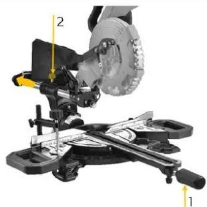
natural_image
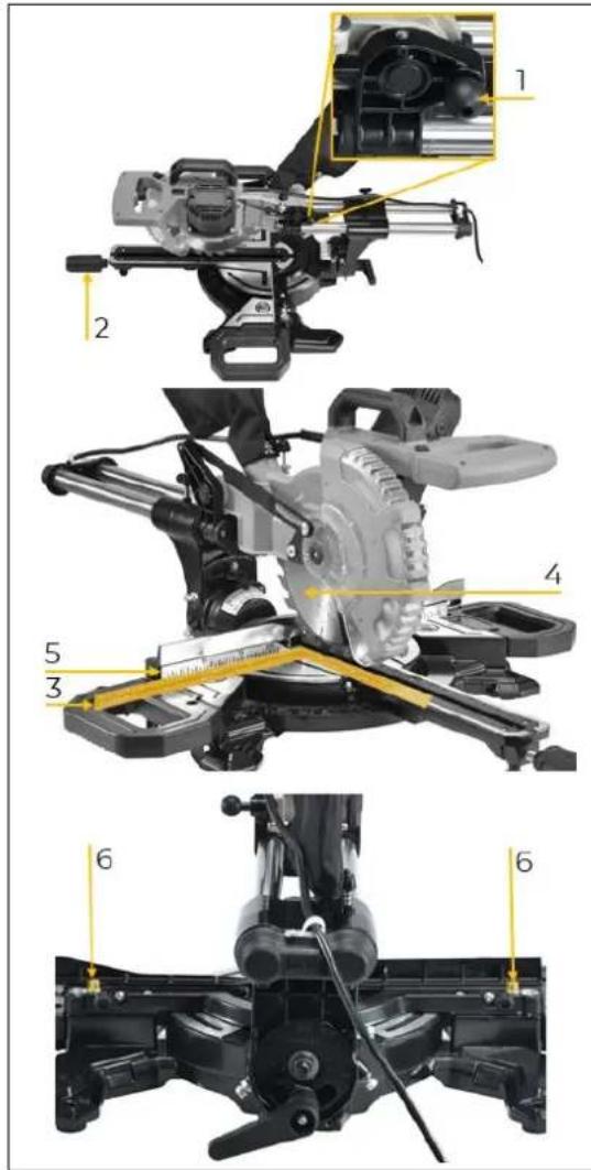
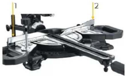
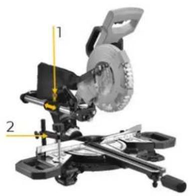
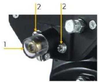
Mechanical assembly diagram showing a cutting tool and workpiece with labeled parts (no readable text or symbols)- Tighten the mitre lock (1) to fix the rotary table.
- Fix the machine head in the rear position using the drag lock (2).
natural_image
Mechanical assembly diagram showing a motor and gear assembly with no visible text or symbolsLocking / unlocking the machine head
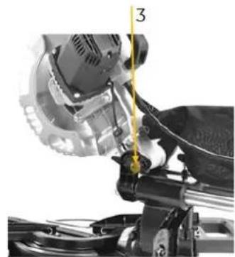
- By slightly pressing down the machine head and simultaneously removing the locking bolt (3) from the motor holder, the saw is released from the lowest / transport position.
NOTE: Please hold the handle and guide the machine head slowly upwards until it reaches the uppermost position. If the handle is released, the machine head will jump up due to the spring preload.
- Press the machine head downwards and fix it by inserting the locking bolt (3).
natural_image
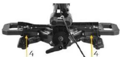
Mechanical assembly with black components and yellow directional arrows indicating force or movement (no text or symbols)- The machine can be carried at both sides of the fixed work table (4).
14 ASSEMBLY
14.1 Preparation
14.1.1 Checking delivery content
Check the delivery immediately for transport damage and missing parts. Report any damage or missing parts to your dealer or the shipping company immediately. Visible transport damage must also be noted immediately on the delivery note in accordance with the provisions of the warranty, otherwise the goods are deemed to have been properly accepted.
14.12 Requirements for the installation site
The selected installation site must ensure a suitable connection to the electrical mains, as well as a connection to an extraction system. Observe the safety requirements and the dimensions of the machine.
Place the machine on a level, solid surface. The chosen installation site of the machine must comply with the local safety regulations as well as the ergonomic requirements for a workplace with sufficient lighting conditions.
Ensure that the selected workplace (machine stand, worktop,...) can bear the load of the machine and that the machine can be attached to it using screws.
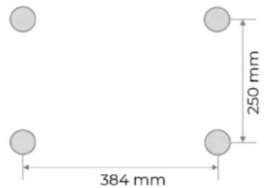
The base of the machine has fixing holes by means of which the machine is firmly connected to the floor. This prevents movement of the machine during operation and possible damage or injury. The machine must be levelled at all support points at the same time. In addition, a distance of at least 0.8 m around the machine must be secured all around. The necessary space for feeding long workpieces must be provided.
NOTE

Required mounting material is not included in the scope of delivery.
natural_image
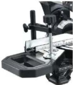
Mechanical assembly diagram showing a cutting tool with yellow measurement lines (no text or symbols)Hole pattern for machine mounting:
Anchoring to the ground
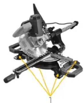
- Anchor both sides of the machine (1) to the floor of the installation site using appropriate fixing bolts.
14.2 Assemble
The machine has been disassembled for transport and must be reassembled before use. Follow the instructions below:
 | Assembly mitre lockScrew the mitre lock (1) into the bore hole on the rotary table (2). |
 | Assembly workpiece supportAttach the two workpiece supports (1) to the left and right of the fixed table of the machine.Use in each case two hexagon socket screws (2) and the Allen key 6 mm (3). |
 | Fasten the sawdust bagPress the metal ring (2) of the sawdust bag (1) together and slide it over the chip collection outlet.After releasing the metal ring (2), the sawdust bag is fixed to the machine. |
 | Assembly downholderThe downholder (1) can be placed to the left or right of the saw blade.To do this, place the downholder (1) in the hole (2) on the machine. |
14.3 Electrical connection
WARNING

Dangerous electrical voltage!
→ The machine may only be connected to the mains supply and the associated checks carried out by a qualified electrician or under the instruction and supervision of a qualified electrician!
- Check, whether the neutral connection and the protective grounding function properly.
- Check, whether the supply voltage and the frequency correspond to the specifications of the machine.
NOTE

Deviation of the supply voltage and frequency!
A deviation from the value of the supply voltage of ± 5% is permissible. A short-circuit fuse must be provided in the power supply system of the machine!
- Use a supply cable of type H07RN (WDE282) or take the required cross-section of the supply cable from a current carrying capacity table. Pay attention to the measures for protection against mechanical damage.
• Make sure that the power source is protected by a residual current circuit breaker. - Connect the device only to a properly grounded outlet.
- When using an extension cable, make sure that the dimension matches the connected load of the machine. The connection power can be found in the technical data, the correlation of cable cross-section and cable lengths can be found in the technical literature or obtain information from a specialist electrician.
• A damaged cable must be replaced immediately.
14.4 Settings
1441 Fine adjustment fence
- Press the machine head downwards and fix it by inserting the locking bolt (1).
- Fix the rotary table in the 0^ -position with the mitre lock (2).
- Place a 90° stop angle (3) on the saw blade (4) and against the fence (5).
- Loosen the screws (6) at both sides with an Allen key and align the fence at an angle of 90^ to the saw blade.
• After adjustment, retighten the screws (6).
14.4.2 Fine adjustment of the angular position 90° (by means of stop angle)

- Fix the rotary table in the 0^ -position with the mitre lock.
- Release the locking lever (1) and set the machine head with the handle to the 0°-position (2).
- Secure the machine head with the locking lever (1) again.
- Place a 90° stop angle (2) between the saw blade and the rotary table.
- Use the adjusting screw (4) to set the angle between the saw blade and the turntable to 90°.
- Then check the position of the angle indicator (3, 5).
- If necessary y, loosen the screw (6) with a Phillips screwdriver and move the pointer (3) to the exact position 0^ on the vertical angle scale (5) and then fix it again.
14.43 Fine adjustment of the angular position 45^ (by means of stop angle)
- Lower the machine head and fix it with the locking bolt.
- Fix the rotary table in the 0^ -position with the mitre lock.
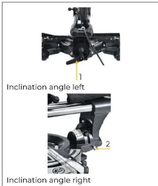
- Adjusting the 45° angle on the left: Release the locking lever (1) and tilt the machine head with the handle to the left into the 45° position then secure it again with the locking lever (1).
- Place a 45^ stop angle (2) between the saw blade and the rotary table.
- With the adjusting screw (2) the saw blade is set at an angle of 45^ to the turntable.
- Adjusting the 45° angle on the right: Release the locking lever (1) and tilt the machine head with the handle to the
natural_image
Close-up of a mechanical device with a ruler and pointer, no visible text or symbolsright into the 45^ position then secure it again with the locking lever (1).
- Place a 45° stop angle (2) between the saw blade and the rotary table.
- With the adjusting screw (3) the saw blade is set at an angle of 45^ to the turntable.
15 OPERATION
Only operate the machine when it is in a perfect condition. Before each operation, a visual inspection of the machine must be carried out. Safety devices and operating elements must be checked carefully. Check screw connections for damage and tight fit.
15.1 Initial check before start
- Check that the speed of the machine is lower than the max. permissible speed of the saw blade used.
- Check saw blade rotation and saw blade dimensions to match the machine.
- Check that the saw blade guard works properly.
- Check whether the connection to a dust collection system is installed.
- Check whether the stops/fences are set correctly and the saw blade is tightened.
- Check whether the machine is fixed on the working plate or a machine stand.
- Check whether the saw blade can run freely.
15.2 Operation
15.21 Setting the angular position of the worktable

- Loosen the mitre lock (1) to set the rotary table to the desired angle.
- At the locking positions, in angles -45^ , -31.6^ , -22.5^ , -15^ , 0^ , 15^ , 22.5^ , 31.6^ and 45^ , the turntable audibly engages.
- The angular position is indicated at the mitre angle scale (3) by means of the indicator (2).
• Fix the rotary table again with the mitre lock (1).
1522 Setting the angular position of the machine head

- Release the locking lever (1) and tilt the machine head to the left or right with the handle (2) until the desired angle is achieved.
- NOTE: To swivel the machine head to the right side (R), proceed as follows:
o Tilt the machine head approx. 10^ to the left. - Press the locking button (6)
- Then swivel the machine head over the 0° line to the right.
- Now you can release the locking button (6) again.
- The pointer (3) indicates the angle of inclination on the scale (4).
• After the desired angle is set, fix the machine head with the locking lever (1).
- To ensure that the machine is standing securely, adjust the tilt lock (5) by turning it so that the machine is stable.
1523 Setting the fences
Front view
natural_image
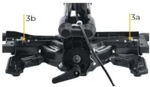
Mechanical device with labeled parts, showing a caliper and lever mechanism (no text or symbols visible)Back side
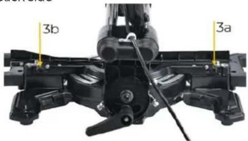
- The two adjustable fences (1 and 2) must be adjusted after changing the machine head angle.
- To do this, loosen the fixing screws (3a and 3a) and adjust the fences so that there is a gap of max. 8 mm between the saw blade and fence.
- Then retighten the fixing screws (3a and 3a) to fix the fences (1 and 2).
NOTE: For a machine head angle of O°-45° to the right, the removable fence (2) must be removed. In this case, the maximum permissible workpiece height is also reduced (see technical data). - Loosen the fixing screw (3b) sufficiently to be able to take off the removable fence (2) upwards.
- After finishing the cut, the removable fence (2) must be refitted.
CAUTION

Before cutting, check that the fences and the saw blade cannot collide (simulated cut with switch-off machine).
1524 Setting cutting depth / cutting depth limiting

natural_image
Mechanical assembly diagram showing a motor and gear assembly with labeled parts (no readable text or symbols)- The cutting depth can be adjusted continuously by turning the screw (1).
• To do this, loosen the knurled nut (2) on the screw (1). - Turn the screw (1) on or off to set the desired cutting depth. Then retighten the knurled nut (2).
NOTE

Check the setting by performing a test cut.
1525 Connection to a dust collection system
For dust extraction in closed rooms, connect a suction hose to the dust extraction nozzle and fix it with a hose clamp. Connection dimensions according to technical data.
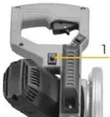
1526 Switch machine ON-OFF
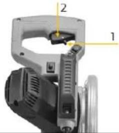
- Switch the machine ON: Press the locking button (1) and then press and hold the ON-OFF switch (2) on the handle.
- Switch the machine OFF: Release the ON-OFF switch (2)
1527 Setting the speed
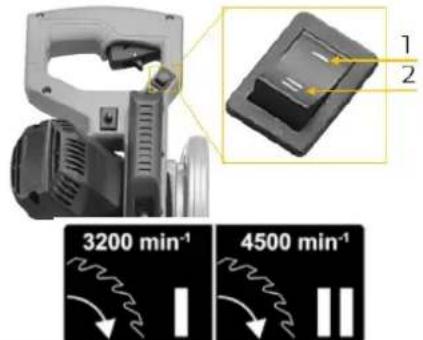
Set the speed-selector switch to the desired speed:
- Pos 1:3200 min ^-1
- Pos II 4500 min ^-1
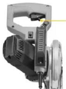
152.8 Switch Laser ON-OFF
natural_image
Close-up of a mechanical device with a yellow arrow pointing to a component labeled '1' (no readable text or symbols beyond the label)- Switch the laser on/off with switch (1).
- The laser indicates the exact cutting line on the workpiece.
15.3 Operation modes
153.1 Mitre cuts
Mitre are particularly suitable for cutting small workpieces (approx. 100 mm) to length.

natural_image
Mechanical cutting machine with labeled parts (1 and 2), no visible text or symbols beyond labels- For mitre cuts, the sliding mechanism is fixed in the rear position by the drag lock (1) so that the machine head cannot slide forwards or backwards during the cut.
- Adjust the angle setting according to the desired operation and adjust the fences accordingly.
• Mark the cutting line (by laser). - Place the workpiece against the fence and table and fix it with the clamp device (2).
- Move the machine head to its uppermost position.
- Switch on the machine and wait until the saw blade has reached full speed.
- Make the mitre cut (move the machine head downwards) until it has reached the lowest position.
- Move the machine head to the uppermost position.
NOTE

Machine head is spring loaded, do not simply release the machine head, instead move the handle upwards until the uppermost position is reached (rest position).
- Release the ON-OFF switch and wait until saw blade comes to stand still.
- Remove workpiece.
1532 Sliding cuts
Sliding cuts are suitable for cutting longer workpieces.
natural_image
Mechanical assembly diagram showing a cutting tool and workpiece with labeled parts (1 and 2), no readable text or symbols present.- For that kind of cuts, the sliding mechanism is unlocked by releasing the drag lock (1) so that the machine head can slide forwards or backwards during the cut.
- Adjust the angle setting according to the desired operation and adjust the fences accordingly.
• Mark the cutting line (by laser). - Place the workpiece against the fence and table and fix it with the clamp device (2).
- Move the machine head to its uppermost position.
- Switch on the machine and wait until the saw blade has reached full speed.
- Perform a sliding cut: To do this, push the machine head forward, then move it downward evenly with light pressure until it reaches the lowest position. Then push the machine head slowly and evenly backward to process the entire length of the workpiece.
- Move the machine head to the uppermost position.
NOTE

Machine head is spring loaded, do not simply release the machine head, instead move the handle upwards until the uppermost position is reached (rest position).
- Release the ON-OFF switch and wait until saw blade comes to stand still.
- Remove workpiece.
15.33 Slot cuts
Set the depth stop for slot cuts so that the desired cutting depth is obtained at the selected angle. Make the mitre or sliding cuts as described in the respective chapter with the difference that the workpiece is not completely cut through.
16 CLEANING, MAINTENANCE, STORAGE, DISPOSAL
WARNING

Dangerous electrical voltage!
→ The machine may only be connected to the mains supply and the associated checks carried out by a qualified electrician or under the instruction and supervision of a qualified electrician!
16.1 Cleaning
Regular cleaning guarantees the long service life of your machine and is a prerequisite for its safe operation.
NOTE

Incorrect cleaning products can attack the finish of the machine. Do not use any solvents, nitro thinners or other cleaning products that could damage the machine's finish. Observe the specifications and instructions of the cleaning agent manufacturer.
- Keep all safety devices, ventilation slots and the motor housing free of dust.
- Therefore, clean the machine after each use and remove any sawdust with a brush, broom or vacuum cleaner.
16.2 Maintenance
The machine is low-maintenance and only a few parts need to be serviced. Malfunctions or defects that could affect your safety must be repaired immediately!
• Before each operation, check the perfect condition of the safety devices.
- Regularly check the perfect and legible condition of the warning and safety labels of the machine.
• Use only proper and suitable tools.
• Use only original spare parts recommended by the manufacturer.
1621 Maintenance plan
The type and degree of machine wear depends to a large extent on the operating conditions. The following intervals apply when the machine is used within the technical limits:
| Interval Components Action | ||
| Before usage | Saw blade Check for damage and replace if necessary. | |
| Saw blade guard | Check function (see function check saw blade protection) | |
| Table inlet | Check for damage and replace if necessary. | |
| Cable Check for damage and repair if necessary. | ||
| After usage | Maschine | Remove dust/wood splinters and dirt |
| Saw blade guard | ||
| Chip bag | ||
| After 50h (/10h) | Carbon brush | Check and replace if necessary. |
| When required Saw balde | Check sharpness of saw blade and replace when necessary | |
1622 Saw blade change
CAUTION

Risk of injury! Wear protective gloves when changing the saw blade.
- Swing the machine head upwards.
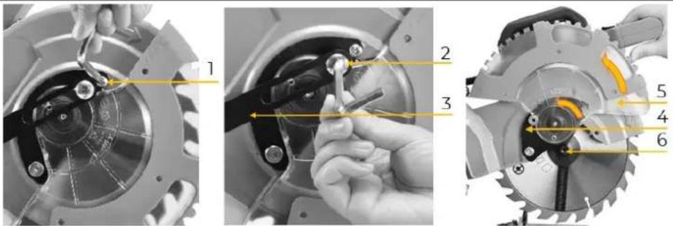
- Loosen the screw (1).
- Loosen the screw (2) and dismantle the support (3).
- Slide the plate (4) and the movable saw blade guard (5) upwards until the flange screw (6) is accessible.
natural_image
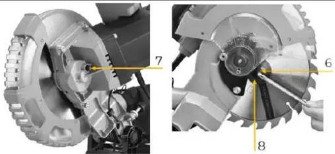
Mechanical assembly diagram showing two views of a robotic arm with labeled parts (no text or symbols present)- Press the spindle lock button (7) with one hand while placing the 6 mm Allen key on the flange screw (6) with the other hand.
• Turn the saw blade until the spindle lock engages. - Now loosen the flange screw (6) with a little more pressure.
NOTE: Left-hand thread!
- Remove the flange screw (6) and the outer flange disc (8).
- Remove the saw blade from the spindle.
- Clean the flange screw (6), the outer flange disc (8) and the inner flange disc.
- Put a new saw blade on the spindle.
NOTE: Ensure the correct direction of rotation!
- P lace the flange screw (6) and the outer flange disc (8) on the spindle and tighten it.
- Return the plate (4) and the movable saw blade guard (5) in their original position.
• Fix the plate (4) again with the screw (1).
• Fix the support (3) and the movable saw blade guard (5) with the screw (2). - Check that the saw blade guard works properly and moves up and down when the machine head is moved (Machine head position up saw blade guard covers the saw.
CAUTION

Pay attention to correct direction of rotation and dimension of the saw blade.
Limits for dimension: Max. Diameter of 210mm and max. thickness of 2.6mm, as well as mounting diameter of 30mm.
- Before continuing with your work, make sure that all safety devices are in good operating condition (Saw blade protection check).
- Important! Whenever changing the saw blade, check that it rotates freely in the table insert, both at vertical and 45° angle settings.
- Important! The work for changing and aligning the saw blade must be carried out correctly.
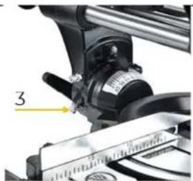
1623 Setting the Laser
- If the laser (1) does not show the correct cutting line any more, you can adjust the laser with the screws (2).
- The laser beam should hit the teeth of the saw blade.
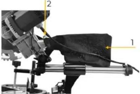
1624 Emptying/changing the sawdust bag
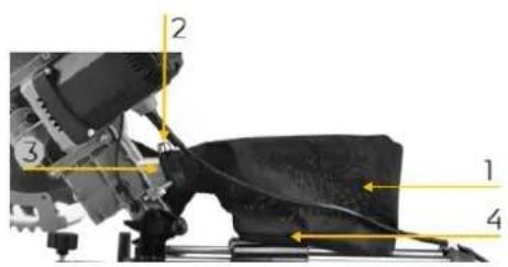
The saw is equipped with a sawdust bag (1).
NOTE: The sawdust bag (1) may only be used for cutting wood and wood-like materials!
- Press the metal ring (2) on the sawdust bag (1) together and fit it to the dust outlet (3).
- After releasing the metal ring (2), the sawdust bag is fixed to the dust outlet.
- The sawdust bag can be emptied by means of a zipper (4).
162.5 Check / change carbon brushes
natural_image
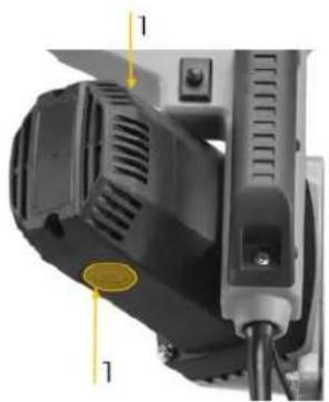
Close-up of a black industrial lamp with ventilation grilles and a yellow circular highlight on the base (no text or symbols visible)- Check the carbon brushes after the first 50 hours of operation with a new machine or when new brushes are fitted. After carrying out the first check, repeat the check every 10 hours of operation.
- If the carbon is worn down to a length of 6 mm, or if the spring or contact wire is burnt or damaged, it is necessary to replace both brushes. If it turns out that the brushes can be used after removal, it is possible to remount them.
- When servicing the carbon brushes, open the two locks (1). Then remove the carbon brushes. Replace the carbon brushes in reverse order.
162.6 Exchange table insert
CAUTION

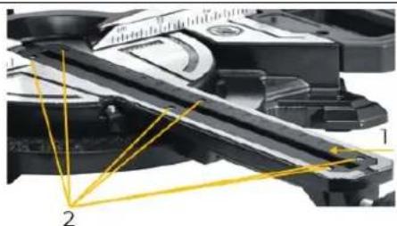
If the table insert (1) is damaged, there is a risk that small parts may become stucked between the table insert and the saw blade and block the saw blade
natural_image
Close-up of a mechanical device with yellow alignment lines and numbered components (no visible text or symbols)- Remove screws (2) from the table insert (1). If necessary, turn the rotary table and machine head to reach the screws.
- Remove the table insert (1).
• Install the new table insert (1). - Tighten the screws (2) on the table insert (1).
16.3 Storage
Store the machine in a dry, frost-proof and lockable place when not in use. Make sure that unauthorised persons and especially children do not have access to the machine.
NOTE

Improper storage can damage and destroy important components. Only store packed or already unpacked parts under the intended ambient conditions!
16.4 Disposal

Observe the national waste disposal regulations. Never dispose of the machine, machine components or operating equipment in the residual waste. If necessary, contact your local authorities for information regarding available disposal options.
If you purchase a new machine or equivalent equipment from your specialist dealer, he is obliged in certain countries to dispose of your old machine properly.
17 TROUBLESHOOTING
WARNING

Dangerous electrical voltage!
→ The mach ine may only be connected to the mains supply and the associated checks carried out by a qualified electrician or under the instruction and supervision of a qualified electrician!
Many possible sources of error can be eliminated in advance if the machine is properly connected to the mains. If you are unable to carry out the necessary repairs properly and/or do not have the required training, always consult a specialist to solve the problem.
| Trouble | Possible cause | Solution |
| Machine doesn’t start | No power supply | Connect to mains |
| Carbon brushes defect | Contact the service team | |
| Motor defect | Contact the service team | |
| ON-OFF-switch defect | Contact the service team | |
| Workpiece kick-back | Dull saw blade | Replace saw blade |
| Wrong assembled saw blade | Check direction / assembly | |
| Wrong cutting angle | Angular position not correct | Adjust the angular position |
18 AVANT-PROPOS (FR)
Cher client, chère cliente !
19.1.1 Restrictions techniques
natural_image
Mechanical assembly diagram showing a cutting tool and workpiece with labeled parts (no text or symbols present)natural_image
Mechanical assembly diagram showing a cam or tool with yellow measurement lines and numbered reference points (no text or symbols present)natural_image
Close-up of a hand holding a tool with numbered arrows pointing to a mechanical component (no text or symbols visible)natural_image
Mechanical tool with a cutting cutter and blade assembly, labeled with number 2 (no text or symbols on the tool itself)natural_image
Mechanical assembly diagram showing a vehicle's frame and suspension components (no text or labels visible)natural_image
Close-up of mechanical components with no visible text or symbolsnatural_image
Close-up of a mechanical device with a lever and scale, no visible text or symbolsnatural_image
Mechanical assembly diagram showing a cutting tool and workpiece with labeled parts (no text or symbols present)Verso
natural_image
Mechanical assembly diagram showing gear and motor components with numbered annotations (no readable text or symbols)natural_image
Close-up of a mechanical device with a highlighted component and a close-up view of a labeled component (no text or symbols visible)natural_image
Close-up of a mechanical power tool with a yellow indicator line and label '1' (no readable text or symbols beyond the label)natural_image
Mechanical assembly diagram showing a cutting tool and workpiece with numbered components (no text or symbols visible)natural_image
Mechanical cutting tool with labeled parts (1 and 2), no visible text or symbols beyond labelsnatural_image
Mechanical assembly diagram showing two views of a motor or gear assembly with numbered components (no text or symbols present)natural_image
Close-up of a black industrial sewing machine with visible exhaust pipes and mounting bracket (no text or symbols)natural_image
Close-up of a mechanical device with yellow laser lines and numbered components (no visible text or symbols)(EN) With original ZIPPER spare parts you use parts that are attuned to each other shorten the installation time and elongate your products lifespan.
NOTE

The installation of parts other than original spare parts leads to the loss of the guarantee! Therefore: When replacing components/parts, only use spare parts recommended by the manufacturer.
Order the spare parts directly on our homepage – category SPARE PARTS or contact our customer service
• via our Homepage – category SERVICE/NEWS - SPARE PARTS REQUEST,
• by e-mail to eg01@zipper-maschinen.at.
Always state the machine type, spare part number and designation. To prevent misunderstandings, we recommend that you add a copy of the spare parts drawing with the spare parts order, on which the required spare parts are clearly marked, especially when not using the online-spare-part catalogue.
| No. | Description |
| 1 Base | |
| 2 Cross pan head three combination M5×30 | |
| 4 Disc positioning spring | |
| 5 Steel ball φ8 | |
| 6 Hexagon headed bolt M8×20 | |
| 7 Plum blossom rubber foot | |
| 8 Left movable support | |
| 9 Small knob 6×28 | |
| 10 | Hexagon socket head screw triple combination M6X30 |
| 11 Positioning frame | |
| 12 Cross pan head screw M6X16 | |
| 13 | Right movable support |
| 14 Rear locking handwheel assembly | |
| 14-1 Cross pan head tapping screw ST4.8X25 | |
| 14-2 Chamfered handwheel spring | |
| 14-3 Rear locking wrench | |
| 14-4 Rear locking insert | |
| 15 Butterfly screw M6*30 | |
| 16 Pull rod locking spring | |
| 17 | Type 2 non-metallic hexagon lock nut M10 |
| 18 | Shim Φ10×Φ25×2 |
| 19 Connecting seat | |
| 20 Hexagon socket head cap screw M6*30 | |
| 21 Hexagon socket head cap screw M6*25 | |
| 22 NUT M6 | |
| 23 Angle conversion screw | |
| 24 | Angle conversion torsion spring |
| 25 Angle block | |
| 26 Hexagon socket flat end screw M10 × 40 | |
| 27 Connecting base ruler | |
| 28 | Cross pan head screw triple combination M4×10 |
| 29 Cutting paving | |
| 30 Disc pointer | |
| 31 Friction block | |
| 32 | Disc locking rod |
| 33 Knob M6*18 | |
| 34 Side handle | |
| 35 Linear bearingΦ25×Φ40×35 | |
| 36 Linear bearing end cap | |
| 37 | Cross recessed countersunk head screw M5*12 |
| 38 Miter pointer | |
| No. | Description |
| 75 Outer pressing plate | |
| 76 Saw blade | |
| 77 Inner pressing plate | |
| 78 | Cross pan head screw triple combination M5*16 |
| 79 Front cover | |
| 80 Rolling bearing 6003 | |
| 81 | Cross recessed countersunk head screw M4*10 |
| 82 Bearing pressing plate | |
| 83 Output shaft | |
| 84 Flat key 4*12 | |
| 85 Big gear wheel | |
| 86 | Shaft bearing retainer 15 |
| 87 Needle roller bearing hk1010 | |
| 88 Gear lock pin | |
| 89 O-ring | |
| 90 Gear box | |
| 91 | Hexagon socket head cap screw triple combination M6*25 |
| 92 Button spring | |
| 93 Gear lock pin cap | |
| 94 Rolling bearing 6001z3 | |
| 95 | Bearing pressing plate |
| 96 | Cross recessed countersunk head screw M5*18 |
| 97 Shaft bearing retainer 12 | |
| 98 Rotor | |
| 99 Cross pan head tapping screw ST4.2*65 | |
| 100 Stator | |
| 101 Rolling bearing 608z3 | |
| 103 Wind shield | |
| 104 Brush holder assembly | |
| 105 Carbon brush | |
| 106 Casing | |
| 107 Cross pan head screw triple combination M5*40 | |
| 108 Speed regulation module | |
| 109 Casing rear cover | |
| 110 Cross pan head tapping screw ST4.2*16 | |
| 111 Cross pan head tapping screw ST4.8*25 | |
| 112 Handle | |
| 113 Ejector rod | |
| 114 Ejector seat | |
| 115 Governor switch | |
| 116 Cross pan head tapping screw ST4.8x35 | |
| 39 | Hexagon socket cylinder head three combination M8 * 25 |
| 40 | Angle conversion ejector rod |
| 41 | Angle conversion ejector rod type 2 non-metallic hexagon lock nut M8 |
| 42 | Flat pad 8 (Φ sixteen × 1.2) |
| 43 | Disk |
| 44 | Cross pan head tapping screw ST4.2*10 |
| 45 | Thread buckle |
| 46 | Pull rod rear cover |
| 47 | Pull rod |
| 48 | Large pan head screw M5*16 |
| 49 | Connecting rod |
| 50 | Hexagon socket flat end screw M6*8 |
| 51 | LED lamp holder |
| 52 | Cross recessed countersunk head screw M4*14 |
| 53 | Bracket |
| 54 | Bolt M6*18 |
| 55 | Self locking pin |
| 56 | O-ring 8×1.5 |
| 57 | Ball nut |
| 58 | Connecting shaft |
| 59 | Large torsion spring |
| 60 | Connecting shaft cover |
| 61 | Transparent coat |
| 62 | Type 2 non-metallic hexagon lock nut M5 |
| 63 | Transparent cover pressing plate |
| 64 | Transparent cover |
| 65 | Transparent cover torsion spring |
| 66 | Inner triangular screw 10 car 6 × 7 large flat head |
| 67 | Cross recessed pan head screw M6*10 |
| 68 | Large cover |
| 69 | Cross pan head screw M5*10 |
| 70 | Small knob M6*40 |
| 71 | Khurled thin NUT M6 |
| 72 | Skull |
| 73 | Plastic thread buckle |
| 74 | Saw blade fixing screw (M8) × 20 left-handed |
| 117 | Upper handle |
| 118 | Capacitance 0.22μF |
| 119 | Circuit board |
| 120 | Microswitch |
| 121 | Wiring block (2 rows) |
| 122 | Switch trigger spring |
| 123 | Trigger as-switch |
| 123-1 | Semicircular head rivet 2 * 18 |
| 123-2 | Self locking torsion spring |
| 123-3 | Self locking piece |
| 123-4 | Switch trigger |
| 124 | Crimping plate |
| 125 | Lower handle |
| 126 | Cable sheath |
| 127 | Cable |
| Laser | |
| 135 | Laser seat |
| 136 | Cross recessed pan head screw triple combination M4x14 |
| 119 | Laser circuit board |
| 137 | Cross recessed countersunk head tapping screw ST3x6 |
| 138 | Laser transparent cover |
| Clamping block assembly | |
| 141 | Fixed rod cover |
| 142 | Handwheel |
| 143 | Fixed rod |
| 144 | Clamping block |
| 145 | Butterfly screw M6x15 |
| 146 | Jaw iron |
| 147 | Non standard screw 6-car M5x7 |
| Plastic wing guard | |
| 148 | Left wing guard |
| 149 | Right wing guard |
| Accessories | |
| 151 | Dust bag |
| 152 | Inner hexagon spanner |
Company ZIPPER Maschinen GmbH grants for mechanical and electrical components a warranty period of 2 years for amateur use; and warranty period of 1 year for professional use, starting with the purchase of the final consumer. In case of defects during this period, which are not excluded by paragraph 3, ZIPPER will repair or replace the machine at its own discretion.
2.) Report:
In order to check the legitimacy of warranty claims, the final consumer must contact his dealer. The dealer has to report in written form the occurred defect to ZIPPER. If the warranty claim is legitimate, ZIPPER will pick up the defective machine from the dealer. Returned shippings by dealers which have not been coordinated with ZIPPER, will not be accepted and refused.
3.) Regulations:
a) Warranty claims will only be accepted, when a copy of the original invoice or cash voucher from the trading partner of ZIPPER is enclosed to the machine. The warranty claim expires if the accessories belonging to the machine are missing.
b) The warranty does not include free checking, maintenance, inspection or service works on the machine. Defects due to incorrect usage of the final consumer or his dealer will not be accepted as warranty claims either. Some examples: usage of wrong fuel, frost damages in water tanks, leaving fuel in the tank during the winter, etc.
c) Defects on wear parts are excluded, e.g. carbon brushes, collection bags, knives, cylinders, cutting blades, clutches, sealings, wheels, saw blades, splitting crosses, riving knives, riving knife extensions, hydraulic oils, oil/air/fuel filters, chains, spark plugs, sliding blocks, etc.
d) Also excluded are damages on the machine caused by incorrect or inappropriate usage, if it was used for a purpose which the machine is not supposed to, ignoring the user manual, force majeure, repairs or technical manipulations by not authorized workshops or by the customer himself, usage of non-original ZIPPER spare parts or accessories.
e) After inspection by our qualified personnel, resulted costs (like freight charges) and expenses for not legitimated warranty claims will be charged to the final customer or dealer.
f) In case of defective machines outside the warranty period, we will only repair after advance payment or dealer's invoice according to the cost estimate (incl. freight costs) of ZIPPER.
g) Warranty claims can only be granted for customers of an authorized ZIPPER dealer who directly purchased the machine from ZIPPER. These claims are not transferable in case of multiple sales of the machine.
4.) Claims for compensation and other liabilities:
The liability of company ZIPPER is limited to the value of goods in all cases. Claims for compensation because of poor performance, lacks, damages or loss of earnings due to defects during the warranty period will not be accepted. ZIPPER insists on its right to subsequent improvement of the machine.
SERVICE
After Guarantee and warranty expiration specialist repair shops can perform maintenance and repair jobs. But we are still at your service as well with spare parts and/or product service. Place your spare part/repair service cost inquiry by
- Mail to service@zipper-maschinen.at.
- Or use the online complaint order formula provided on our homepage – category service/news.
30 DÉCLARATION DE GARANTIE (FR)
1.) Garantie
(EN) We monitor the quality of our delivered products in the frame of a Quality Management policy.
Your opinion is essential for further product development and product choice. Please let us know about your:
- Impressions and suggestions for improvement.
- Experiences that may be useful for other users and for product design
- Experiences with malfunctions that occur in specific operation modes
We would like to ask you to note down your experiences and observations and send them to us via E-Mail or by post:


- INHALT / INDEX
- Komponenten / Components / Composants
- Technische Daten / Technical data / Données techniques
- Please read and note the safety instructions!
- Check the goods immediately after receipt and note any complaints on the consignment note when taking over the goods from the deliverer!
- Copyright
- Customer service contact
- Intended use of the machine
- NOTE
- Technical restrictions
- Prohibited applications / Dangerous misuse
- User Requirements
- Safety devices
- General safety instructions
- Electrical safety
- Special safety instructions for this machine
- Instructions for the use of the LASER:
- Hazard warnings
- Residual risks
- Hazardous situations
- DANGER
- WARNING
- CAUTION
- TRANSPORT
- Lifting / Setting down
- Carrying
- Transport of the assembled machine
- Locking / unlocking the machine head
- ASSEMBLY
- Preparation
- Checking delivery content
- Requirements for the installation site
- Anchoring to the ground
- Assemble
- Electrical connection
- Dangerous electrical voltage!
- Deviation of the supply voltage and frequency!
- Settings
- Fine adjustment fence
- Fine adjustment of the angular position 90° (by means of stop angle)
- Fine adjustment of the angular position 45° (by means of stop angle)
- OPERATION
- Initial check before start
- Operation
- Setting the angular position of the worktable
- Setting the angular position of the machine head
- Setting the fences
- Setting cutting depth / cutting depth limiting
- Connection to a dust collection system
- Switch machine ON-OFF
- Setting the speed
- Switch Laser ON-OFF
- Operation modes
- Mitre cuts
- Sliding cuts
- Slot cuts
- CLEANING, MAINTENANCE, STORAGE, DISPOSAL
- Cleaning
- Maintenance
- Maintenance plan
- Saw blade change
- NOTE: Left-hand thread!
- NOTE: Ensure the correct direction of rotation!
- Setting the Laser
- Emptying/changing the sawdust bag
- Check / change carbon brushes
- Exchange table insert
- Storage
- Disposal
- TROUBLESHOOTING
- AVANT-PROPOS (FR)
- Cher client, chère cliente !
- Restrictions techniques
- 2.) Report:
- 3.) Regulations:
- 4.) Claims for compensation and other liabilities:
- SERVICE
- DÉCLARATION DE GARANTIE (FR)
- 1.) Garantie
Brand : Zipper
Model : ZIKGS210DS
Category : Saw