
ZIBAS205 - Saw Zipper - Free user manual and instructions
Find the device manual for free ZIBAS205 Zipper in PDF.
| Product type | Band saw |
| Brand | Zipper |
| Model | ZIBAS205 |
| Category | Saw |
| Power supply | 230 V ~ 50 Hz, fuse 20 A, mandatory grounding |
| Main functions | Longitudinal, cross, diagonal, curved, circular cuts; cutting of dowels and wedges |
| Safety devices | Adjustable saw blade guard (max. 3 mm), safety switch on front doors, push stick, parallel stop |
| Adjustments | Guard height, table tilt (0-45°), blade tension and tracking, upper/lower guides, parallel stop |
| Working techniques | Longitudinal cut with stop, diagonal cut with accessories, curved cut with narrow blade, circular cut with device |
| Cleaning | After each use: remove chips and sawdust; do not use solvents; lubricate bare parts with acid-free oil |
| Regular maintenance | Before each use: check safety, nuts, belt, blade condition; monthly: belt, stickers, throat plate, bearings |
| Blade replacement | Unplug, open doors, release tension, remove old blade, thread new blade respecting cutting direction, tension with handwheel |
| Drive belt replacement | Only for ZI-BAS250 (not applicable to ZIBAS205) |
| Throat plate | Replace if damaged or worn: remove by pressing from below, insert new one |
| Dust extraction connection | Mandatory; air speed ≥ 20 m/s (dry wood) or ≥ 28 m/s (wet); antistatic hoses |
| Ambient conditions | Humidity max. 65%, operating temperature +5 to +40 °C, storage -20 to +55 °C |
| Allowed materials | Wood and materials with similar physical properties |
| Prohibited use | Cutting firewood, metal materials, humid or explosive environment |
| Warranty | 2 years non-commercial use, 1 year commercial; wear parts excluded |
| Spare parts | Available on order via form with machine type and part number |
| User manual | 131 pages, available in FR, DE, EN, ES; translations on request |
Frequently Asked Questions - ZIBAS205 Zipper
User questions about ZIBAS205 Zipper
0 question about this device. Answer the ones you know or ask your own.
Ask a new question about this device
Download the instructions for your Saw in PDF format for free! Find your manual ZIBAS205 - Zipper and take your electronic device back in hand. On this page are published all the documents necessary for the use of your device. ZIBAS205 by Zipper.
USER MANUAL ZIBAS205 Zipper
natural_image
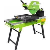
Green ZIPPER ZI-BAS205 industrial machine with mechanical components and control panel (no visible text or symbols on the machine body)
natural_image
Green ZIPPER ZI-DA5250 industrial milling machine with control panel and base plate (no visible text or symbols on main body)ZI-BAS205
EAN: 9120039233529
ZI-BAS250
EAN: 9120039233536
1 INHALT /INDEX / ÍNDICE
1 INHALT /INDEX / ÍNDICE 2
2 SICHERHEITSZEICHEN / SAFETY SIGNS / SEÑALES DE SEGURIDAD / SYMBOLES DE SÉCURITÉ / ZNAKOVI ZA SIGURNOST 8
3 TECHNIK / TECHNICS / TÉCNICA / TECHNIQUE / TEHNIKA 10
3.1 Lieferumfang / Delivery content / Volumen de suministro / Contenu de la livraison / Opseg isporuke.... 10
3.2 Komponenten / Components / Componentes / Composants / Komponente . 11
3.3 Technische Daten / Technical date / Datos técnicos / Données techniques / Tehnički podaci....12
4 VORWORT (DE) 14
5 SICHERHEIT 15
13.1 Intended use of the machine.... 36
13.1.1 Technical Restrictions 36
13.1.2 Prohibited Use / Forseeable Misuse....36
13.2 User Requirements.... 36
13.3 Safety Devices.... 37
13.4 General safety instructions.... 37
13.5 Electrical Safety 38
13.6 Safety instructions for wood band saws 38
13.7 Hazard warnings 38
14 TRANSPORT 39
15 ASSEMBLY 39
15.1 Preparatory activities.... 39
15.1.1 Delivery content....39
15.1.2 Workplace requirements ....39
15.2 Secure the bandsaw to the floor.... 40
15.3 Assembly 40
15.4 Power Supply 41
15.5 Connecting to a dust collection system 42
16 ADJUSTMENTS 42
16.1 Open and close the front doors.... 43
16.2 Selection of saw bands.... 43
16.3 Tensioning/changing the saw blade.... 44
16.4 Adjusting band saw blade tracking.... 45
16.5 Adjusting the saw band guide 45
16.5.1 Adjusting upper saw band guide 45
16.5.2 Adjusting lower saw band guide....46
16.6 Height-adjustment of the blade guard 47
16.7 Adjusting the tilt of the worktable.... 47
16.8 Adjusting the work table at right angles to the saw blade.... 48
16.9 Adjusting the saw table lateral alignment.... 48
16.10Adjusting the rip fence 48
17 OPERATION 49
17.1 Important operating instructions 49
17.1.1 Before you start working....49
17.1.2 Before each work step 49
17.1.3 After work....49
17.2 Switching On and Off 49
17.3 Working techniques.... 50
17.3.1 Longitudinal cutting of narrow (thin) workpieces....50
17.3.2 Diagonal cut....50
17.3.3 Cutting tenons....50
17.3.4 Cutting wedges....50
17.3.5 Cutting Curves....51
17.3.6 Cutting with a template, handling shaped work....51
17.3.7 Cutting circular work ....51
17.3.8 Fixtures 51
18 CLEANING, MAINTENANCE, STORGE, DISPOSAL 52
18.1 Cleaning 52
18.2 Maintenance....52
18.2.1 Replacement of the V-belt (only for ZI-BAS250) 53
18.2.2 Replacement of the table insert....53
19 DISPOSAL 53
20 TROUBLESHOOTING 54
21 PRÓLOGO (ES) 55
22 SEGURIDAD 56
natural_image
Four blue circular icons representing different workplace safety symbols: walking, boot, helmet, and helmet (no text or labels)DE Persönliche Schutzausrüstung tragen! EN Wear personal protective equipment! ES iUse el equipo de protección individual! FR Porter un équipement de protection individuelle! HR Nosite osobnu zaštitnu opremu!


DE Warnung vor spitzem (scharfem) Werkzeug. EN Warning of pointed (sharp) tool. ES Advertencia de herramientas puntiagudas (afiladas) FR Avertissement contre les outils pointus (tranchants) HR Upozorenje na šiljaste (oštre) alate. DE Sicherheitsabstand halten. EN Keep safety distance. ES Mantener la distancia de seguridad. FR Respecter une distance de sécurité. HR Održavajte sigurnosni razmak.
DE Achtung Verletzungsgefahr! EN Caution risk of injury! ES Atención iRiesgo de sufrir lesiones! FR Attention, risque de blessure! HR Oprez, opasnost od ozljede!

EN Push the door to close to the machine with one hand, and rotat the knob counter clockwise with the other hand
EN Warning signs and/or stickers on the machine which are illegible or have been removed must be replaced immediately!
| N° | Bezeichnung / Description | Qty | N° | Bezeichnung / Description | Qty |
| 1 | Maschine / Machine / Máquina / Machine / Stroj | 1 | 5 | Tischeinlage / Table insert / Suplemento de la mesa / Plaque de platine / Uložak za stol | 1 |
| 2 | Schiebestock / Push stick / Bastón de corredera / Bâton d'insertion Štap za guranje | 1 | 6 | Bedienungsanleitung / Operator's manual / Instrucciones de uso / Mode d'emploi / Uputa za uporabu | 1 |
| 3 | Arbeitstisch / Work table / Mesa de trabajo / Table de travail / Radni stol | 1 | 7 | Werkzeug-Set / Tool kit / Juego de herramientas / Set d'outils / Komplet alata | 1 |
| 4 | Parallelanschlag / Rip fence / Tope paralelo / Guide longitudinal Paralelni graničnik | 1 |
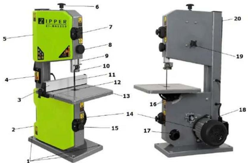
3.2 Komponenten / Components / Componentes / Composants / Komponente
ZI-BAS205

ZI-BAS250
ZI-BAS250 / ZI-BAS205
| 1 | Befestigungspunkte / Fastening points / Puntos de sujeción / Points de fixation / Točke za pričvršćivanje | 11 | Sägeblatt / Saw blade / Hoja de la sierra / Lame de scie / List pile |
| 2 | Untere Fronttür / Lower front door / Puerta frontal inferior / Porte avant inférieure / Donja prednja vrata | 12 | Tischeinlage / Table insert / Suplemento de la mesa / Plaque de platine / Uložak za stol |
| 3 | Parallelanschlag / Rip fence / Tope paralelo / Guide longitudinal / Paralelni graničnik | 13 | Arbeitstisch / Work table / Mesa de trabajo / Table de travail / Radni stol |
| 4 | EIN-AUS-Schalter / ON-OFF-Switch / Interruptor On/Off / Interrupteur MARCHE-ARRÊT / Prekidač za uključivanje/isključivanje | 14 | Motor / Motor / Motor / Moteur / Motor |
| 5 | Obere Fronttür / Upper front door / Puerta frontal superior / Porte avant supérieure / Gornja prednja vrata | 15 | Klemmrad - Fronttür / Clamping wheel - wheel cover door / Rueda de fijación -Puerta frontal / Molette de serrage de porte avant / Kotačić za zatezanje prednjih vrata |
| 6 | Handrad für Sägeblattspannung / Hand wheel for blade tension / Volante manual para tensar la hoja de la sierra / Volant de serrage de lame de scie / Kotačić za zatezanje lista za piljenje | 16 | Tisch-Winkelmesser Arbeitstisch / Bench angle gauge for work table / Goniómetro para la mesa de trabajo / Goniomètre de la table de travail / Kutomjer za mjerenje nagiba radnog stola |
| 7 | Klemmrad - Fronttür /Clamping wheel - wheel cover door / Rueda de fijación-Puerta frontal / Molette de serrage de porte avant / Kotačić za zatezanje prednjih vrata | 17 | Absaugstutzen / Dust collector port /Tubuladuras de aspiración / Tubulured'aspiration / Usisni nastavak |
| 8 | Handrad zur Einstellung der Sägebandabdeckung/Hand wheel for blade guard / Volante manual para ajustar la inclinación de la hoja de la sierra / Volant de réglage du capot de la scie à ruban / Kotačić zapodešavanje poklopca trake za piljenje | 18 | Netzkabel und Stecker /Power cord and Plug / Cables y enchufes /Câble d'alimentation et fiche / Strujni kabel i utikač |
| 9 | Verstellbare Sägebandabdeckung /Adjustable saw blade guard / Cubierta ajustable para la hoja de la sierra / Capot réglable de scie à rubant / Podesivi poklopac trake za piljenje | 19 | Handrad zur Einstellung der Sägebandlauf /Hand wheel for saw blade trackingadjustment / Volante manual para ajustar lamarcha de la hoja de la sierra / Volant deréglage de la course de la scie à ruban /Kotačić za podešavanje hoda trake zapiljenje |
| 10 | Obere Sägeblattführung /Upper saw blade guide / Guía superior de la hoja de lasierra / Guidage supérieur de la scie à ruban / Gornjavodilica trake za piljenje | 20 | Schiebestock / Push stick / Bastón decorredera / Bâton d'insertion / Štap zaguranje |
3.3 Technische Daten / Technical date / Datos técnicos / Données techniques / Tehnički podaci
| Spez. | ZI-BAS205 ZI-BAS250 | ||
| Motor / motor / Motor / Moteur / Motor | |||
| Spannung / Voltage / Tensión / Napon | V/Hz | 230-240 / 50 | 230-240 / 50 |
| Motorleistung / Motor power / Potencia del motor / Puissance du moteur / Snage motora | W 250 S2(15min) 500 S1 | ||
| Motordrehzahl / Speed / Régimen de revoluciones del motor / Vitesse de rotation du moteur Broj okretaja motora | min-1 1487 2982 | ||
| Schutzart / IP-rating / Grado de protección / Classe Vrsta zaštite | IP | 20 | 20 |
| Ausladung - max. Schnittbreite / Throat - max. cutting width / Descarga - Ancho máx. de corte / Longueur - largeur max. de l'objet à découper / Maks. Širina rezanja | mm | 195 | 245 |
| Schnitthöhe bei 90° / Cutting height at 90° / Altura de corte a 90° / Hauteur de coupe à 90° / Visina reza pri 90° | mm | 80 | 115 |
| Schnitthöhe bei 45° / Cutting height at 45° / Altura de corte a 45° / Hauteur de coupe à 45° / Visina reza pri 45° | mm | 45 | 65 |
| Schnittgeschwindigkeit / Cutting speed / Velocidad de corte / Vitesse de coupe / Brzina rezanja | m/min | 950 | 800 |
| Bandsägerollen ∅ / Band saw roll ∅ / ∅ rollos de cinta de sierra / ∅ du rouleau de la scie à ruban / ∅ kola tračne pile | mm | 205 | 255 |
| Sägebandlänge / Sawband length / Longitud de la cinta de la sierra / Longueur de la scie à ruban / Dužina trake za piljenje | mm | 1400 | 1712 |
| Sägebandbreite / Sawband width / Anchura de la cinta de la sierra / Largeur de la scie à ruban / Širina trake za piljenje | mm | 3.5-12 | 3.5-12 |
| Dimensionen des Arbeitstisches / Worktable dimensions / Dimensiones de la mesa de trabajo / Dimensions de la table de travail / Dimenzije radnog stola | mm | 302 x 304 | 302 x 304 |
| Arbeitstischneigung / Worktable tilt angle / Inclinación de la mesa de trabajo / Inclinaison de la table de travail / Nagib radnog stola | ° | 90°-45° | 90°-45° |
| Tischhöhe / Height from ground / Altura de la mesa / Hauteur de table / Visina stola | mm 268.5 338.5 | |
| Gesamthöhe / Total height / Altura total / Hauteur totale / Ukupna visina | mm 640 792 | |
| Absaug-Anschluss ∅ (innerer Durchmesser) / Dust collector port ∅ (inner diameter) / ∅ conexión de aspiración (diámetro interior) / Raccord d'aspiration ∅ (diamètre intérieur) / ∅ (unutarnji promjer) usisnog priključka | mm 34 34 | |
| notwendiger Luft-Volumenstrom (bei 20 m s-1) / required air flow rate (at 20 m s-1) / Caudal volumétrico de aire necesario (con 20 m s-1) / Volume de débit d'air nécessaire (à 20 m s-1) Potrebni volumenski protok zraka (pri 20 m s-1) | m^3 h^-1 565 565 | |
| Nettogewicht / Net weight / Peso neto / Poids net Neto težina | kg 16.9 24 | |
| Bruttogewicht / Gross weight / Peso bruto / Poids brut / Bruto težina | kg 18.3 25.9 | |
| Verpackungsmaße / Packaging dimensions / Dimensiones del embalaje / Dimensions d'emballage / Dimenzije ambalaže | mm 727 x 30 x 390 | 880 x 352 x 450 |
| Schalldruckpegel LPA (ISO 11203) * / Sound pressure level LPA (ISO 11203) * / Nivel de presión sonora LPA (ISO 11203) * / Niveau de pression acoustique LPA (ISO 11203) * / Niveau de pression acoustique LPA (ISO 11203) * Razina zvučnoq tlaka LPA (ISO 11203) * | dB (A) 82.6 k=3 82.3 k=3 | |
| Schallleitungspegel LWA (ISO3744) * / Sound power level LWA (ISO3744) * / Nivel de potencia sonora LWA (ISO3744) * / Niveau de puissance sonore LWA (ISO3744) * Razina zvučne snage LWA (ISO3744) * | dB (A) 93.6 k=3 94.4 k=3 |
* (DE) Hinweis Geräuschangaben: Die angegebenen Werte sind Emissionswerte und müssen damit nicht zugleich auch sichere Arbeitsplatzwerte darstellen. Obwohl es eine Korrelation zwischen Emissions- und Immissionspegeln gibt, kann daraus nicht zuverlässig abgeleitet werden, ob zusätzliche Vorsichtsmaßnahmen notwendig sind oder nicht. Faktoren, welche den am Arbeitsplatz tatsächlich vorhandenen Immissionspegel beeinflussen, beinhalten die Eigenart des Arbeitsraumes und andere Geräuschquellen, d. h. die Zahl der Maschinen und anderer benachbarter Arbeitsvorgänge. Die zulässigen Arbeitsplatzwerte können ebenso von Land zu Land variieren. Diese Information soll jedoch den Anwender befähigen, eine bessere Abschätzung von Gefährdung und Risiko vorzunehmen.
* (EN) Notice noise emission: The values given are emission values and therefore do not have to represent safe workplace values at the same time. Although there is a correlation between emission and immission levels, it cannot be reliably deduced whether additional precautions are necessary or not. Factors influencing the actual immission level at the workplace include the nature of the workspace and other noise sources, i.e. the number of machines and other adjacent operations. The permissible workplace values may also vary from country to country. However, this information should enable the user to make a better assessment of hazard and risk
* (ES) Aviso sobre los valores de ruido: Los valores indicados son valores de emisión y, por lo tanto, no representan necesariamente al mismo tiempo valores seguros en el lugar de trabajo. Aunque hay una correlación entre los niveles de emisión y los de inmisión, no se puede deducir con certeza si es necesario adoptar medidas de precaución adicionales o no. Entre los factores que influyen en el nivel de inmisión real en el lugar de trabajo, se encuentran la naturaleza del espacio de trabajo y otras fuentes de ruido, es decir, el número de máquinas y otros procesos de trabajo adyacentes. Asimismo, los valores admisibles en el lugar de trabajo pueden variar de un país a otro. No obstante, esta información debe capacitar al usuario a evaluar mejor los peligros y los riesgos.
* (FR) Avis Données sur le bruit : Les valeurs indiquées sont des valeurs d'émission et ne représentent donc pas nécessairement des valeurs de sécurité sur le lieu de travail. Bien qu'il existe une corrélation entre les niveaux d'émission et d'immission, il est impossible de déduire de manière fiable si des mesures de précaution supplémentaires sont nécessaires ou non. Les facteurs influençant le niveau d'immission réellement présent sur le lieu de travail comprennent les caractéristiques de la salle de travail et d'autres sources de bruit, c'est-à-dire le nombre de machines et d'autres processus de travail adjacents. Les valeurs autorisées sur le lieu de travail peuvent également varier d'un pays à l'autre. Toutefois, ces informations devraient permettre à l'utilisateur de mieux évaluer le danger et le risque.
* (HR) Napomena o emisiji buke: navedene vrijednosti su vrijednosti emisije i ne moraju istovremeno predstavljati i sigurne vrijednosti na radnom mjestu. Iako postoji korelacija između razina emisije i imisije, iz toga se ne može pouzdano zaključiti jesu li ili nisu potrebne dodatne mjere opreza. Čimbenici koji utječu na stvarnu razinu imisije na radnom mjestu obuhvaćaju specifičnost radnog prostora i druge izvore buke, tj. broj strojeva i drugih radnih procesa u blizini. Dopuštene vrijednosti na radnom mjestu mogu se razlikovati i u različitim državama. Ali ove bi informacije korisniku trebale omogućiti da izvrši procjenu opasnosti i rizika.
4 VORWORT (DE)
natural_image
3D diagram of a mechanical component with labeled point B (no text or symbols present)4. Montage des Parallelanschlags
HINWEIS

natural_image
Diagram of a pulley system with a belt and wheel, no text or symbols present
Vorgehensweise:
Vorgehensweise:
natural_image
Two technical line drawings showing hands operating a mechanical device with no visible text or symbolsnatural_image
Line drawings of two laboratory setups: one with a person operating a mechanical device, the other with a wooden frame (no text or symbols)natural_image
Two technical line drawings showing a 3D printer on a base and a hand operating a mechanical device (no text or symbols present)natural_image
Two technical line drawings showing a worker operating machinery on a workbench, with no visible text or symbols.natural_image
Mechanical device with labeled parts M and S, no visible text or symbols beyond labelsThis user manual contains information and important notes for safe start-up and handling of the wood band saw model ZI-BAS250, ZI-BAS205 for simplification purposes hereinafter referred to as "machine".

The manual is part of the machine and must not be removed. Keep it for later use in a suitable place, easily accessible to users (operators), protected from dust and moisture, and enclose it with the machine if it is passed on to third parties!
Pay special attention to the chapter Safety!
Due to the constant further development of our products, illustrations and contents may differ slightly. If you notice any errors, please inform us.
Technical changes reserved!
Check the goods immediately after receipt and note any complaints on the consignment note when taking over the goods from the deliverer!
Transport damage must be reported separately to us within 24 hours.
ZIPPER-MASCHINEN cannot accept any liability for unnoticed transport damage.
Copyright
© 2020
This documentation is protected by copyright. All rights reserved! Especially the reprint, the translation and the extraction of photos and illustrations will be prosecuted.
The place of jurisdiction shall be the Regional Court of Linz or the court responsible for 4707 Schlüsselberg.
Customer service contact
This section contains information and important notes on safe commissioning and handling of the machine.

For your own safety, read these operating instructions carefully before putting the machine into operation. This will enable you to handle the machine safely and prevent misunderstandings as well as personal injury and damage to property. In addition, observe the symbols and pictograms used on the machine as well as the safety and hazard information!
13.1 Intended use of the machine
The machinery is intended exclusively for the following operations:
For longitudinal and cross cuts of wood and materials with similar physical properties as wood within the given technical limits.
ZIPPER-MASCHINEN assumes no responsibility or warranty for any other use or use beyond this and for any resulting damage to property or injury.
13.1.1 Technical Restrictions
The machine is intended for use under the following ambient conditions:
Relative humidity: max. 65 %
Temperature (for operation) +5°C bis +40°C
Temperature (for storage and/or transport) -20^ C bis +55^ C
13.1.2 Prohibited Use / Forseeable Misuse
- Operating the machine without adequate physical and mental aptitude.
- Operating the machine without knowledge of the operating instructions
- Operating the machine outside the technical limits specified in this manual.
• Changes in the design of the machine. - Modify, circumvent or disable the safety devices of the machine.
- Remove the safety markings attached to the machine.
- Operating the machine in wet and rainy conditions.
- Operating the machine in a potentially explosive environment (machine can generate ignition sparks during operation)
The improper use or disregard of the versions and instructions described in this manual will result in the voiding of all warranty and compensation claims against Zipper Maschinen GmbH.
13.2 User Requirements
The machine is designed for operation by one person. The physical and mental aptitude as well as knowledge and understanding of the operating instructions are prerequisites for operating the machine. Persons who, because of their physical, sensory or mental abilities or their inexperience or ignorance, are unable to operate the machinery safely must not use it without supervision or instruction from a responsible person.
Please note that local laws and regulations may determine the minimum age of the operator and restrict the use of this machine!
Put on your personal protective equipment before working on the machine.
Work on electrical components or equipment may only be carried out by a qualified electrician or under the instruction and supervision of a qualified electrician.
13.3 Safety Devices
The machine is equipped with the following safety devices:
 | The saw blade guard protects against accidental contact with the saw blade and from flying chips.In order to provide adequate protection, the upper saw blade cover must always be placed as close as possible to the workpiece (max. distance 3 mm). |
| Door safety switch: one safety switch each on the inside of the covering of the upper and lower wood band saw roll. | |
| Push stick | Use a push stick to prevent the hands from being too close to the saw blade when working! |
13.4 General safety instructions
To avoid malfunctions, damage and health hazards when working with the machine, the following points must be observed in addition to the general rules for safe working:
- Before start-up, check the machine for completeness and function. Only use the machine if the guards and other non-parting guards required for machining have been fitted, are in good operating condition and have been properly maintained.
- Choose a level, vibration-free, non-slip surface for the installation location.
- Ensure sufficient space around the machine!
- Ensure sufficient lighting conditions at the workplace to avoid stroboscopic effects.
- Ensure a clean working environment.
- Only use perfect tools that are free of cracks and other defects (e.g. deformations).
- Remove tool keys and other adjustment tools before switching on the machine.
- Keep the area around the machine free of obstacles (e.g. dust, chips, cut parts, etc.).
- Check the strength of the machine connections before each use.
- Never leave the running machine unattended. Switch off the machine before leaving the working area and secure it against unintentional or unauthorised recommissioning.
- The machine may only be operated, serviced or repaired by persons who are familiar with it and who have been informed of the hazards arising from this work.
- Ensure that unauthorised persons maintain a safe distance from the machine and keep children away from the machine.
- When working on the machine, never wear loose jewellery, loose clothing, ties or long, open hair.
- Hide long hair under hair protection.
- Wear close-fitting protective clothing and suitable protective equipment (eye protection, dust mask, ear protection; gloves only when handling tools).
- Work on the machine should only be carried out in well-ventilated rooms. If necessary, use dust protection.
- If there are connections for dust extraction, make sure that they are properly connected and in working order.
• Always work with care and the necessary caution and never use excessive force.
- Do not overload the machine!
- Shut down the machine and disconnect it from the power supply before carrying out any adjustment, conversion, cleaning, maintenance or repair work. Before starting any work on the machine, wait until all tools or machine parts have come to a complete standstill and secure the machine against unintentional restarting.
- Do not remove any sections or other parts of the workpiece from the cutting area while the machine is running!
- Do not remove splinters and chips by hand! Use a sliding stick for this purpose!
- Use a push stick for cutting operations!
- Do not work on the machine if it is tired, not concentrated or under the influence of medication, alcohol or drugs!
- Do not use the machine in areas where vapours from paints, solvents or flammable liquids represent a potential danger (danger of fire or explosion!).
- Do not smoke in the immediate vicinity of the machine (fire hazard)!
13.5 Electrical Safety
- Make sure that the ON/OFF switch is in the "OFF" position before connecting the machine to the power source.
- Do not use the power tool if it cannot be switched on and off with the ON/OFF switch.
• Proper plugs and matching sockets reduce the risk of electric shock. - Ensure that the unit is earthed.
- There is an increased risk of electric shock if your body is in ground contact. Avoid physical contact with earthed objects, such as pipes, radiators, etc.
- Water that penetrates power tools increases the risk of electric shock. Do not expose the power tools to rain or moisture.
• Only use suitable extension cords. - A damaged or tangled cable increases the risk of electric shock. Handle the cable carefully. Never use the cable to carry, pull or disconnect the power tool. Keep the cable away from heat, oil, sharp edges or moving parts.
- Use of the power tool in a humid environment is only permitted if the power source is protected by a residual current circuit breaker.
- Always shut down the machine before carrying out any conversion, adjustment, measuring, cleaning, maintenance or repair work and always disconnect it from the power supply for maintenance or repair work. Before starting any work on the machine, wait until all tools or machine parts have come to a complete standstill and secure the machine against unintentional restarting.
13.6 Safety instructions for wood band saws
• Work with gloves on rotating parts is not permitted!
- Replace torn and deformed saw blades immediately, they cannot be repaired.
- Never clean the band saw blade or the wood band saw rollers of the machine while running with a brush or scraper held in the hand.
- Only use sharpened tools.
- Never remove parts of the workpiece from the cutting area while the machine is running.
- Do not use the machine to cut fire wood.
- When cutting boards in upright position, use aids to prevent kick-back.
- When cutting round or irregularly shaped wood, use a device to stop the workpiece from twisting.
• Risk of injury to hands/fingers from the saw blade during operation.
• Risk of injury/cutting hazard due to deburred cutting edges.
• Risk of injury due to contact with live components.
- Risk of injury due to breakage or ejection of the saw blade or parts thereof, especially in the event of overloading or incorrect running direction of the saw blade.
- Excessive noise can cause hearing damage and temporary or permanent hearing loss. Wear hearing protection certified to health and safety regulations to limit noise exposure.
- Risk to the respiratory tract from harmful emissions of wood dust.
• Risk of injury to the eye from flying parts, also with protective goggles.
- During operation of the machine wood dust is generated. Therefore, connect the machine to a suitable dust collection system during installation!
• Always switch on the dust collection system before you start machining the workpiece!
13.7 Hazard warnings
Despite their intended use, certain residual risks remain. Due to the design and construction of the machine, hazardous situations may occur when handling the machines, which are identified as follows in these operating instructions:
DANGER

A safety instruction designed in this way indicates an imminently hazardous situation which, if not avoided, will result in death or serious injury.
WARNING

Such a safety instruction indicates a potentially hazardous situation which, if not avoided, may result in serious injury or even death.
CAUTION

A safety instruction designed in this way indicates a potentially hazardous situation which, if not avoided, may result in minor or moderate injury.
NOTICE

A safety notice designed in this way indicates a potentially hazardous situation which, if not avoided, may result in property damage.
Irrespective of all safety regulations, your common sense and appropriate technical suitability/training are and will remain the most important safety factor for error-free operation of the machine. Safe working depends primarily on you!
14 TRANSPORT
WARNING

When handling the machine, ensure the correct posture or respectively use suitable means of transport (such as forklift trucks, pallet trucks, etc.).
Observe any instructions and information on the transport packaging with regard to centre of gravity, attachment points, weight, means of transport to be used and prescribed transport position, etc.
Two persons are recommended for transport and installation.
If you transport the machine with a vehicle, ensure that it is protected against slipping, shocks and vibration.
Never lift the machine by the worktable or by the hand wheels, but only by the frame or by the base where the holes for fixing the machine to the ground are located. Make sure, that the blade guard is in lower position when the machine is being transported.
When lifting, carrying and depositing the load, make sure that you are in the correct posture:
• Lifting, Depositing:
Ensure stability when lifting / setting down (legs hip width).
Lift / lower load with bent knees and straight back (like weightlifter).
Do not lift / lower the load jerkily.
- Carrying:
Carry load with both hands as close to body as possible.
Carry load with straight back.
15 ASSEMBLY
15.1 Preparatory activities
15.1.1 Delivery content
Please check the product contents immediately after receipt for any eventual transport damage or missing parts. Claims from transport damage or missing parts must be placed immediately after initial machine receipt and unpacking before putting the machine into operation. Please understand that later claims cannot be accepted anymore.
15.1.2 Workplace requirements
The workplace has to fulfill the requirements. Please consider the safety requirements. The worktop has to be even, in level and vibration-resistant. It must be suitable at least to weight it with double weight per square meter than the machines net weight.
The chosen workplace must have access to a suitable electric supply net hat complies with the machines requirements. A distance of at least 0.8 m round the machine must be guaranteed.
An adequate distance must be provided for the feeding of long workpieces in front of and behind the machine.
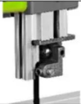
15.2 Secure the bandsaw to the floor

natural_image
3D mechanical component with green and gray parts, labeled B (no text or symbols on the object itself)Secure the wood band saw to the floor at the place of installation using screws to prevent the machine from tipping over during operation. The machine base has a total of four through holes (B) for this purpose - see illustration on the left.
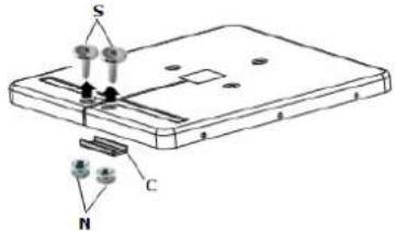
15.3 Assembly
The machine is delivered almost ready for operation. Prior to operation, the machine must only be secured against tipping over and the following components must be attached or mounted:
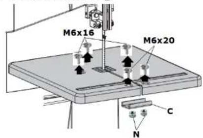
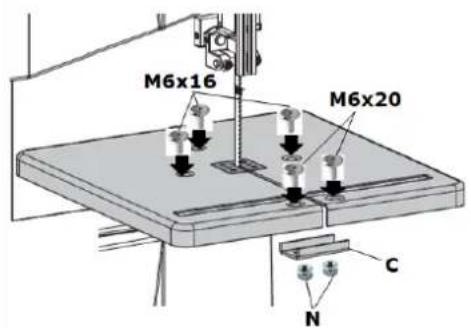
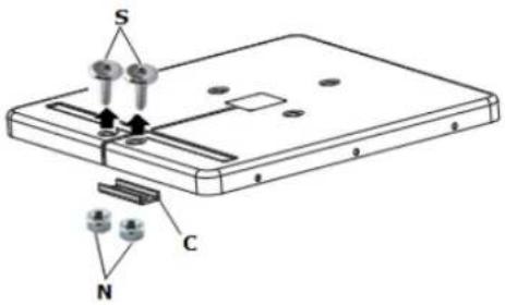 | Assembly of the worktableDismantle the two screws M6x20 (S), the two nuts (N) and the clamp (C) from the worktable. |
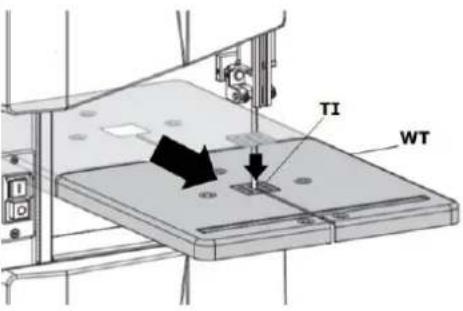  | Lift the work table (WT) to the mounting position on the bench angle gauge (B). Thread the saw blade into the work table (WT).Position the table inlay (TI) on the work table properly.NOTICECheck that the table inlay is at the same height as the machine table. |
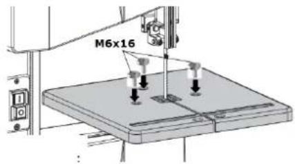 | Fasten the worktable to the bench angle gauge (B) using three screws (M6x16), three washers and three nuts (M6). |
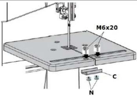 | 2. Assembly of the clampMount the clamp (C) using two screws (M6x20) and two nuts (N). |
 | 3. Assembly of the push stickFix the screw (M6x35) with the nut (M6) onto the machine.Only tighten the screw with the nut on the machine to a point where a secure hold is guaranteed and the push stick (PS) can be hung on it. |
 | 4. Assembly of the rip fencePosition the rip fence (RF) on the worktable.The rip fence is fixed by turning the locking lever (LL) downwards.To release the fixation, the locking device has to be turned upwards.The rip fence can be applied to both sides of the saw blade. |
 | 5. Machine assembly completed |
15.4 Power Supply
WARNING

Dangerous electrical voltage! Connection of the machine as well as electrical inspections, maintenance and repair may only be carried out by qualified personnel or under the supervision and supervision of a qualified electrician!
WARNING

When working with non-grounded machines: Severe injury or even death may arise though electrocution!
Therefore: The machine must be operated at a grounded power socket.
The connection of the machine to the electric power supply and the following checks have to be carried out by a respectively trained electrician only.
- The electronic connection of the machine is designated for operation with a grounded power socket (Mains voltage 230 V)!
• The connector plug may not be manipulated.
• The grounding wire should be held in green-yellow.
• The mains supply must be secured with 20A. - Check that the mains voltage complies with the requirements of the machine.
- In case of repair or replacement, the grounding conductor must not be connected to a live box!
- Make sure that a possible extension cord is in good condition and suitable for the transmission of power. An undersized cord reduces the transmission of power and heats up.
• A damaged cable must be replaced immediately
NOTICE

Operation is only allowed with safety switch against stray current (RCD max. stray current of 30mA).
NOTICE

Use only permitted extension cable with cross-section the one in the following table declared.

| Voltage | Extension | Cross-section |
| 220 V-240 V50 Hz | <27 m | 1,5 mm^2 |
| <44 m | 2,5 mm^2 | |
| <70 m | 4,0 mm^2 | |
| <105 m | 6,0 mm^2 |
15.5 Connecting to a dust collection system
NOTE

The machine must be connected to dust collection system. The system must start up at the same time as the motor of the wood band saw starts. For materials with a humidity < 12% , the air velocity at the dust collector port and in the hoses must be at least 20~m / s (for moist chips with a humidity >12% , at least 28~m / s ). The suction hoses used must be flame-retardant (DIN4102 B1), permanently antistatic (or grounded on both sides) and comply with the relevant safety regulations.
Information on the dust collection System:
Refer to technical data
16 ADJUSTMENTS
WARNING

Dangerous electrical voltage! Always disconnect the machine from the power source before carrying out any adjustment work and secure it against unintentional restarting!
In order to ensure the desired precision of the machine, certain basic settings must be made before commissioning, which are described below.
16.1 Open and close the front doors
ZI-BAS205
ZI-BAS250
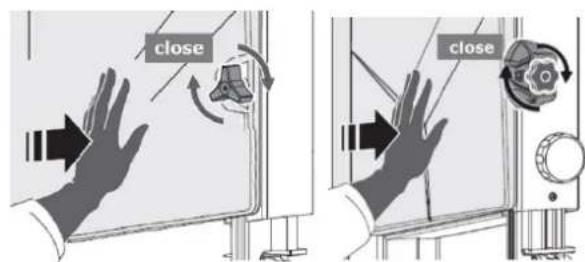
ZI-BAS205
ZI-BAS250
Open the front door:
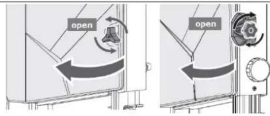
- ZI-BAS205: Rotate the hand wheel counterclockwise to open the front door.
- ZI-BAS250: Rotate the hand wheel clockwise to open the front door.
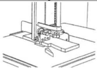
Close the front door:
- ZI-BAS205: Push the front door with one hand to the wheel housing, and rotate the hand wheel clockwise with the other hand.
- ZI-BAS250: Push the front door with one hand to the wheel housing, and rotate the hand wheel counterclockwise with the other hand.
16.2 Selection of saw bands
CAUTION

Always wear gloves when handling wood band saw blades. Handle the wood band saw blades carefully to prevent damage. Unused, untensioned band saw blades should be folded and stored securely in a (child-) safe, dry place. Always check saw blades for damaged teeth and cracks before use!
Select the band saw blade according to the material to be cut. Narrow band saw blades are suitable for curved and circular cuts, wide band saw blades for straight cuts. For hard wood you need finer toothed band saw blades, for soft wood you should use coarser toothed band saw blades.

natural_image
Three line drawings showing hands holding a circular object, a twisted rope, and a ring-like structure (no text or symbols)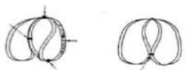
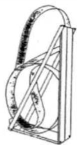
Correct winding of saw bands
natural_image
Simple line drawing of a mechanical device with a curved handle and internal components (no text or symbols)Band saw blade transport device
Dimensions of the saw bands
Refer to technical data
16.3 Tensioning/changing the saw blade
Procedure for exchanging the saw blade:
 | Disconnect machine from the power supply.Loosen the two screws M6x20 (S) and nuts (N).Remove the u-shaped clamp (C) from the worktable.Open the upper and lower front door (F). |
 | Release the saw blade tension with the hand wheel (H).Turn the hand wheel counter-clockwise: the band saw blade tension is reduced.Turn hand wheel clockwise: the band saw blade tension is increased.Unthread the old band saw blade through the work table and the table insert.ATTENTION: For this purpose use cut-proof gloves! |
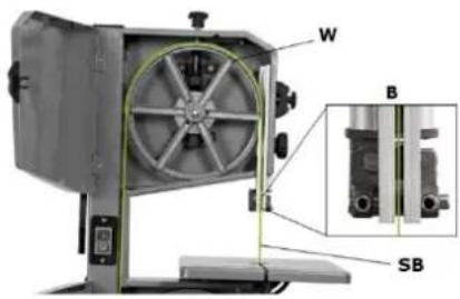 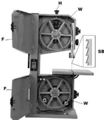 | Thread the new saw blade (SB) into the work table and into the table insert.In the next step, place new saw band (SB) in the bearings (B) of the saw band guide, then place it in the middle of the rubber tracks of the two band saw wheels (W).ATTENTION: note the cutting direction! The teeth of the band saw blade must point downwards in the cutting direction and towards the front of the machine.Tension the band saw blade with the hand wheel (H).NOTICEThe saw band tension must be adjusted according to the saw band width.Close the upper and lower front door (F).Mount the clamp (K) back on the worktable using two M6x20 screws (S) and two nuts (M).To check whether the band saw blade is correctly positioned in the rubber bands of the two band saw wheels (W), let the machine run for at least one minute; stop the machine, open the upper and lower front doors and check the settings and, if necessary, readjust the band saw blade run using the hand wheel for band saw blade tracking adjustment (see paragraph 16.4).Adjust the saw band guide. |
NOTICE
- Close the upper and lower front door (F).
- Mount the clamp (K) back on the worktable using two M6x20 screws (S) and two nuts (M).
- To check whether the band saw blade is correctly positioned in the rubber bands of the two band saw wheels (W), let the machine run for at least one minute; stop the machine, open the upper and lower front doors and check the settings and, if necessary, readjust the band saw blade run using the hand wheel for band saw blade tracking adjustment (see paragraph 16.4).
- Adjust the saw band guide.
CAUTION

If the tension is too high, the saw band may tear - risk of injury! If the tension is too low, the driven band saw roller may spin and the band saw blade may stop. Therefore check the saw band tension before each start-up!
A correct saw blade tension is essential for a long service life of the saw blade and to ensure the quality of sawing.
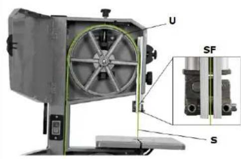
16.4 Adjusting band saw blade tracking
If the band saw blade tracking does not run properly (centred), the band saw blade tracking must be readjusted.

Procedure:
- Clamping screw (CS) must be loosened.
- The hand wheel (HW) must be tilted either forwards or backwards.
- Turn the hand wheel clockwise: the upper wheel is tilted towards the front door.
- Turn hand wheel counter clockwise: the upper wheel is tilted backwards.
- Tighten the clamping screw (CS).
- Check the saw blade tracking again.
This procedure may have to be repeated several times to ensure correct running.
16.5 Adjusting the saw band guide
NOTE

Adjust the saw band guide only after the blade tension and the running of the saw band have been adjusted and checked. Correct adjustment of the saw blade guide is important. The saw band becomes unusable if the teeth touch the guides while the saw band is running.
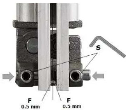
16.5.1 Adjusting upper saw band guide
The upper saw band guide consists of the following components:
- Rear thrust bearing
- Lateral guide discs
Rear thrust bearing
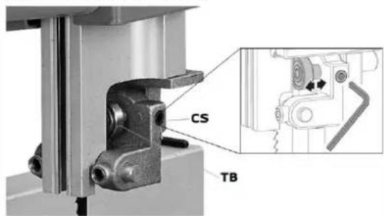
The thrust bearing (TB) prevents the saw blade from being pushed back strongly during the cut.
Procedure:
- To adjust, loosen the clamping screw (CS) and position the rear thrust bearing (TB) at a distance of about 0.5 mm from the saw band back.
- Then tighten the clamping screw (CS) again.
Lateral guide discs

The lateral guide pins should slightly strip the saw band to obtain a vibration-free and straight cut.
Procedure:
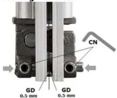
- To a djust, loosen the clamping nuts (CN) and press the lateral guide discs (GD) up to 0.5 mm to the saw band.
- Then retighten the clamping nuts (CN).
16.5.2 Adjusting lower saw band guide
The upper saw band guide consists of the following components:
- Rear thrust bearing
- Lateral guide discs
Rear thrust bearing

Procedure:
- Loosen the two screws (M6x20) and nuts (N). Remove the u-shaped clamp (C) from the worktable.
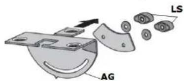
- To disassemble the worktable from the bench angle gauge (AG), loosen the three screws (M6x16), washers and nuts (N).
- Raise the upper blade guide fully (see 16.6).
- Loosen the two locking screws (LS) and remove the bench angle gauge (AG).
- Open the lower front door (F).
- To adjust, loosen the clamping screw (CS) and position the rear thrust bearing (TB) at a distance of about 0.5 mm from the saw band back.
- Then tighten the clamping screw (SC) again.
Lateral guide discs
Procedure:
- To adjust, loos en the clamping nuts (CN) and press the lateral guide discs (GD) up to 0.5 mm to the saw band.
- Then retighten the clamping nuts (CN).
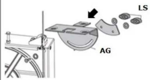
- Mount the bench angle gauge (AG) with the two locking screws (LS).
- Close the lower front door (F).
- Fix the worktable with three screws M6x16, three washers and three nuts (M6) to the bench angle gauge (AG).
- Fix the u-shaped clamp (K) with two screws (M6x20) and two nuts (M).
16.6 Height-adjustment of the blade guard

ZI-BAS205

The blade guard protects against unintentional contact with the saw blade and against flying chips.
- ZI-BAS205: loosen the locking screw (LS) by turning it counter clockwise.
- To adjust the height between blade guard and workpiece, turn the hand wheel (H) until the desired height is reached.
ATTENTION: Always lower the upper saw band guide as close as possible (max. 3 mm) to the workpiece.
- ZI-BAS205: retighten the locking screw (LS) by turning it clockwise.
16.7 Adjusting the tilt of the worktable
The following steps are necessary to adjust the cutting angle:
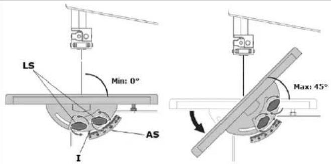
- After loosening both locking screws (LS), the work table tilts steplessly through 45° to the blade.
- By means of the angle scale (AS) the inclination angle can be read off the indicator (I).
- Retighten the locking screws (LS) after adjusting the inclination of the worktable.
16.8 Adjusting the work table at right angles to the saw blade
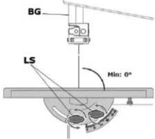 | Raise upper blade guide (BG) fully.Loosen the two locking screws (LS) on bench angle gauge. |
 | Using a try square (TS), set the table at right angle to the blade and tighten the locking screws (LS) again. |
 | Loosen locking nut (LN) and adjust the limit stop screw (SS) until it touches the work table (WT).Tighten locking nut (LN) again. |
16.9 Adjusting the saw table lateral alignment
 | Procedure:To disassemble the worktable from the bench angle gauge, loosen the three screws (M6x16), washers and nuts.Align the work table in a position where the saw band runs through the middle of the table insert (T).Tighten the three screws (M6x16) again. |
16.10 Adjusting the rip fence
The rip fence is clamped to the front and can be used on both sides of the blade.
17 OPERATION
17.1 Important operating instructions
Device to be operated in a perfect state only. Inspect the device visually every time it is to be used. Check in particular the safety equipment, electrical controls, electric cables, operating components and screwed connection for damage and if tightened properly. Replace any damaged parts before operating the device.
17.1.1 Before you start working
- Check the workpiece for foreign objects, cracks and loose knots.
• General technical condition of the machine.
• Safety equipment available and in working order.
• All the components for correct fit and function. - Moving parts are not blocked.
• If all tools have been removed from the machine for service / maintenance.
• Use only sharp, crack-free and sufficiently set saw blades. - Check that the saw blade on the band saw wheel is correctly tensioned and aligned.
- Check the saw blade guide for correct adjustment.
• Have any necessary aids (e.g.: rip fence, push stick, etc.) ready.
• If gloves are required for workpiece handling, they must be finger-free.
17.1.2 Before each work step
- Wait until the sawband has reached full speed – then performing the cut!
• Never switch the machine on while pressing the blade against the material! - Move the adjustable guard for the band saw blade as close as possible to the workpiece.
-
When feeding the workpiece, do not place your hands on the workpiece in the area of the cutting plane.
• Feed the workpiece at a constant speed and constant pressure.
• Use aids for safe workpiece guidance: -
When cutting workpieces standing on edge, secure them against tilting (e.g. by means of rip fence).
- Secure round workpieces against twisting with a wedge support.
- For long or wide workpieces, ensure good workpiece support (e.g. by widening or lengthening the table).
- Never remove splinters or chips by hand while the saw blade is running.
17.1.3 After work
- Switch machine off, wait for standstill.
- Remove wood chips and splinters from cutting area and table insert.
• Lower the saw blade cover onto the work table. - To protect the running surfaces of the wheels, detension the band saw blade and attach a warning sign to the machine reminding you that the saw blade tension must be reset before the next use.
17.2 Switching On and Off

ON-switch (I): starting the machine
OFF-switch(0): stopping the machine
17.3 Working techniques
CAUTION

When cross-cutting a round or irregularly shaped workpiece, it is necessary to secure the workpiece with a suitable template or holding device and to use a suitable band saw blade (for cross section)!
17.3.1 Longitudinal cutting of narrow (thin) workpieces

natural_image
Line drawing of hands using a tool to adjust or install a mechanical component (no text or symbols present)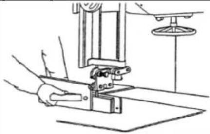
natural_image
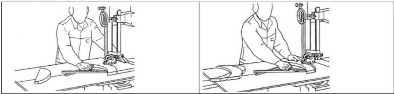
Line drawing of a hand operating a mechanical device with a lever and base plate (no text or symbols)Longitudinal cutting is sawing parallel to the wood fibre. For rectangular cuts (table at right angles to the saw blade), place the rip fence to the left of the saw blade to guide the workpiece safely along the fence with your right hand. For longitudinal mitre cuts with an inclined table, attach the parallel stop to the right of the saw band on the downward side (if the width of the workpiece permits this) in order to secure the workpiece against slipping.
Use a sliding stick to prevent the hands from being too close to the band saw blade!
17.3.2 Diagonal cut

natural_image
Line drawing of a person operating a lathe machine in a lab setting (no text or symbols)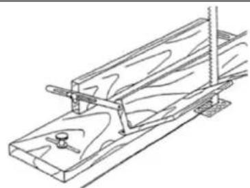
natural_image
Line drawing of a wooden plank with a clamping tool (no text or symbols)For diagonal cuts, use auxiliary devices as shown in the illustrations above.
17.3.3 Cutting tenons
natural_image
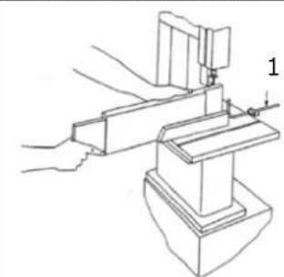
Technical line drawing of a mechanical assembly with hands and a numbered component (no text or symbols)1 Stop, fixed to the table
17.3.4 Cutting wedges

natural_image
Technical line drawing of a mechanical assembly or mounting bracket (no text or symbols)
natural_image
Line drawing of a person using a mechanical device to adjust or install a component (no text or symbols visible)17.3.5 Cutting Curves

natural_image
Two technical line drawings showing a person operating machinery on a workbench, no text or symbols present.When cutting curves, pay particular attention to the width of the saw blade. Choose a narrow band saw blade with which you can cut even the smallest radii in your workpiece. Work at a low feed rate so that you do not push the workpiece sideways out of the cutting line.
17.3.6 Cutting with a template, handling shaped work
| Working with a template | Correct handling of moulded parts |
17.3.7 Cutting circular work
| To cut round slices, use a circular cutting device as shown in the illustrations on the left and below! |
17.3.8 Fixtures
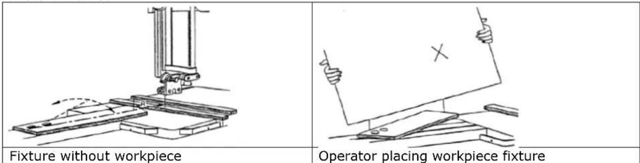
18 CLEANING, MAINTENANCE, STORGE, DISPOSAL
WARNING

Handling the machine with the power supply on, may lead to serious injuries or even death. Always disconnect the machine from the power supply before cleaning, servicing or maintenance work and secure it against unintentional reconnection!
18.1 Cleaning
CAUTION

Never clean the band saw blade or the band saw rollers with a brush held in the hand or with a scraper while the machine is running. Always wait until the machine has come to a complete standstill!
NOTE

Wrong cleaning agents can attack the varnish of the machine. Do not use solvents, nitro thinners, or other cleaning agents that could damage the machine's paint. Observe the information and instructions of the cleaning agent manufacturer!
Prepare the surfaces and lubricate the bare machine parts with an acid-free lubricating oil. Subsequently, regular cleaning is a prerequisite for the safe operation of the machine and its long service life. Therefore, clean the device after each use of chips and dirt particles.
18.2 Maintenance
WARNING

Danger due to electrical voltage! Handling the machine with the power supply up may result in serious injury or death. Always disconnect the machine from the power supply before servicing or maintenance work and secure it against unintentional restart!
The machine is low-maintenance and only a few parts have to be serviced. Nevertheless, malfunctions or defects which could impair the safety of the user must be rectified immediately!
| Intervall | Component | Measure |
| Before operating the machine | Safety devices | Check the condition |
| Nuts, Bolts Check if securely tightened | ||
| Drive belt | Check the condition. If necessary tension it. | |
| Saw band | Check the condition. If necessary replace it. | |
| After every use of the machine | Machine | Clean the machine from chips and sawdust. |
| Wheel housings Vacuum off chips and sawdust | ||
| Saw band guide | Lubricate the saw blade guide slightly with acid-free lubricating oil | |
| Thrust bearing Guide discs | Keep guide discs and the thrust bearing free from deposits | |
| Saw band Slacken the saw blade | ||
| Monthly | Drive belt | Check the condition. If necessary replace it. |
| Security stickers | Check the condition. If necessary replace them. | |
| Table insert | Check the condition. If necessary replace it. | |
| Thrust bearing Guide discs | Check the condition and replace them replace if they are worn out. | |
18.2.1 Replacement of the V-belt (only for ZI-BAS250)
NOTE

Always keep the V-belt correctly tensioned. A belt that is too loose weakens the power transmission (drive and braking effect), too much tension leads to excessive stress on the belt (heating).
natural_image
Mechanical device with labeled parts M and S, no visible text or symbols beyond labelsAt the back

Front

natural_image
Close-up of a mechanical device with labeled parts (S, M) and no visible text or symbols beyond labelsLoose V-Belt tension
- Disconnect the machine from the power supply.
- Remove the saw b lade. Proceed as described in section 0.
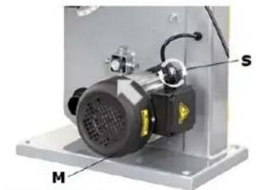
- Loosen the screw (S) which fixes the motor (M) to the exterior of the housing.
- Reduce the tension of the V-belt (AR) by pushing the motor (M) upwards.
Change the V- belt
- Loosen the shaft circlip (SC).
- To remove the drive belt (DB), push the saw wheel (SW) with the motor pulley (MP) off the shaft.
- Replace the old drive belt with a new one.
- Reinstall lower saw wheel (SW) with the motor pulley (MP) by sliding it back onto the shaft.
- Secure with the shaft circlip (SC).
- Place the new drive belt (DB) partially around the motor pulley (MP), then turn the wheel by hand until the drive belt (DB) is completely seated on the motor pulley (MP).
Tension the V- belt
- Tension the drive belt by moving the motor (M) downwards.
To check the drive belt tension, press inwards in the middle of the belt with a force of three to four kilograms. The tension is correct if the drive belt does not yield more than 1.2 cm.
- When the tension of the belt is at the desired level, retighten the screw (S) that was previously loosened.
- To reattach the saw blade, proceed as described in section 0.
18.2.2 Replacement of the table insert
The table insert needs to be replaced when its slot has become enlarged or damaged.
Procedure:
- Remove the table insert from the work table by pushing up from underneath.
• Fit a new table insert.
19 DISPOSAL
Observe the national waste disposal regulations. Never dispose of the machine, machine components or equipment in residual waste. If necessary, contact your local authorities for information on the disposal options available.
If you buy a new machine or an equivalent device from your specialist dealer, he is obliged in certain countries to dispose of your old machine properly.
20 TROUBLESHOOTING
WARNING

Danger due to electrical voltage! Handling the machine with the power supply up can lead to serious injuries or even death. Always disconnect the machine from the power supply before servicing or maintenance work and secure it against unintentional or unauthorised reconnection!
Many possible sources of error can be excluded in advance if the machine is properly connected to the mains.
If you are unable to carry out necessary repairs properly and/or do not have the required training, always consult a specialist to solve the problem.
| Trouble | Possible cause | Solution |
| Motor does not work | 1. Front doors open (limit switch)2. Motor, cable or plug defective3. Fuses burned | 1. Close front doors exactly2. Contact an electrician3. Contact an electrician |
| The motor starts up slowly and does not reach operating speed | 1. Voltage too low2. Coils damaged3. Capacitor burned | 1. Contact an electrician2. Contact an electrician3. Replacement of the capacitor by a qualified electrician |
| Motor makes excessive noise | Motor defect | Replacement of the motor by a qualified electrician |
| Motor does not reach its full power | Circuits in the network are overloaded (other motors, etc.) | Do not use any other equipment or motors on the same circuit |
| Motor overheats easily | 1. Overloading of the motor2. Insufficient cooling of the motor | 1. Avoid overloading the motor while cutting.2. Remove dust from the motor in order to ensure optimal cooling of the motor |
| Saw cut is rough or wavy | 1. Saw blade is dull2. Tooth shape is not appropriate for the material thickness | 1. Resharpen the saw blade2. Use a suitable saw blade |
| Workpiece pulls away and/or splinters | Excessive cutting pressure and/or the saw blade is not suitable for use | Insert a suitable saw blade |
| Saw blade is not running straight | 1. Saw band guide has been wrongly set2. Wrong saw band | 1. Set the saw blade guide according to the operating instructions2. Select a saw blade according to the operating instructions |
| Burn marks appear on the wood during the cutting work | 1. Blunt saw blade2. Wrong saw blade | 1. Change the saw blade2. Select a saw blade according to the operating instructions |
| Saw blade jams during cutting work | 1. Blunt saw blade2. Deposits on the saw blade3. Saw band guide has been set poorly | 1. Change the saw blade2. Clean the saw blade3. Set the saw blade guide according to the operating instructions |
21 PRÓLOGO (ES)
iEstimado cliente!:
natural_image
3D mechanical component with green and gray parts, labeled B (no text or symbols on the part itself)AVISO

natural_image
Mechanical assembly diagram showing a component with labeled parts S and H, no readable text or symbols present.
natural_image
Mechanical diagram showing two configurations of pulley systems with rotating wheels and rotational links (no text or labels)Procedimiento:
natural_image
Mechanical assembly diagram showing a bracket with labeled components V and D, and an inset view of a mechanical component (no text or symbols present)Procedimiento:
natural_image
Two technical line drawings showing hands operating a mechanical device with a base plate (no text or symbols present)natural_image
Line drawings of two laboratory setups: one with a person operating a bench, the other with a wooden frame (no text or symbols)natural_image
Line drawings of a sewing machine and a hand operating a workbench (no text or symbols)26.3.5 Cortes en curva
natural_image
Two technical line drawings showing a worker operating machinery on a workbench, with no visible text or symbols.Cher client, chère cliente,
30.1.1 Restrictions techniques
natural_image
3D mechanical component with a green highlighted section and labeled point B (no text or symbols beyond labels)Procédure :
Procédure :
natural_image
Two technical line drawings showing hands operating a mechanical device with no visible text or symbolsnatural_image
Line drawings of two laboratory apparatus setups: a person using a vertical tool and a wooden bench with a handle (no text or symbols)natural_image
Two technical line drawings showing a printer and a hand operating a mechanical device (no text or symbols present)natural_image
Two technical line drawings showing a person operating machinery on a workbench, with no visible text or symbols.natural_image
3D diagram of a mechanical component with labeled point B (no text or symbols present)6. Montaža kopče
- Kopču (K) montirajte s pomoću dvaju vijaka (M6x20) i dviju matica (M).

7. Montaža štapa za guranje
8. Montaža paralelnog graničnika
- Paralelni graničnik (P) postavite na radni stol. - Paralelni graničnik pričvršćuje se zakretanjem mehanizma za zaključavanje (V) prema dolje. - Za otpuštanje mehanizam za zaključavanje (V) zakreće se prema gore. - Paralelni graničnik može se postaviti na obje strane trake za piljenje.
natural_image
Pure mechanical diagram of a frame structure without any text, numbers, or symbols- Stroj odvojite od strujne mreže.
- Uklanjanje kopče (K) s radnog stola: demontirajte dva vijka M6x20 (S) i dvije matice (M).
- Otvorite gornja i donja prednja vrata (F).
- Otpustite traku za piljenje s pomoću kotačića (H).
- Okretanje kotačića suprotno od kazaljke na satu: smanjuje se zategnutost trake za piljenje.

natural_image
Mechanical assembly with labeled component S and H, no readable text or symbols presentPostupak:
- U tu svrhu treba najprije otpustiti sigurnosni vijak (S) na kotačiću (H).
- Gornje se kolo kotačićem može nagnuti unaprijed ili unatrag.
natural_image
Mechanical diagram showing two configurations of pulley systems with rotating gears and a belt (no text or labels)- Okretanje kotačića suprotno od kazaljke na satu: kolo se naginje natrag.
Stražnji potisni ležaj (D) sprečava jako potiskivanje trake unatrag za vrijeme rezanja.
Postupak:
- Za podešavanje otpustite zaporni svornjak (V), a stražnji potisni ležaj (D) postavite na udaljenost od oko 0,5 mm od trake za piljenje.
- Nakon toga opet pritegnite zaporni svornjak (V).
Bočni vodeći ležaj
Bočni vodeći ležajevi trebaju lagano dodirivati traku za piljenje kako bi se dobio revni rez bez vibracija.
Postupak:
- Za podešavanje otpustite sigurnosne matice (S), a vodeći ležaj (F) približite traci za piljenje do 0,5 mm.
- Ponovno pritegnite sigurnosne matice (S).
41.5.2 Donja vodilica trake za piljenje
natural_image
Two technical line drawings showing hands operating a mechanical device with no visible text or symbols.natural_image
Line drawing of a person operating a lathe machine in a lab setting (no text or symbols)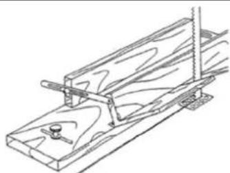
natural_image
Technical line drawing of a wooden clamp or clamping device with no visible text or symbolsnatural_image
Technical line drawing of a mechanical assembly with no visible text or symbols1 graničnik, pričvršćen za stol
42.3.4 Rezanje klinova
natural_image
Technical line drawing of a mechanical assembly or mounting bracket (no text or symbols)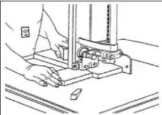
natural_image
Line drawing of a hand using a mechanical device to press or install components (no text or symbols visible)natural_image
Line drawing of a person operating a workbench with tools and equipment (no text or symbols)
natural_image
Line drawing of a person operating machinery on a workbench (no text or symbols)Kod zaobljenih rezova posebno pazite na širinu trake za piljenje. Izaberite usku traku za piljenje kojom ćete moći izrezati i najmanje radijuse koji se javljaju na vašem obratku. Obradak pomičite malom brzinom kako ga ne biste bočno izgurali iz crte reza.
42.3.6 Šablone / oblikovani dijelovi
ZI-BAS250
flowchart
graph TD
    A["230-240V~ 50Hz"] --> B["Power Supply Cord"]
    B --> C["Crown"]
    C --> D["Close-End Wire Connector"]
    D --> E["Crown"]
    E --> F["Crown"]
    F --> G["Motor"]
    H["Micro Switch (Lower Housing Door)"] --> I["Crown"]
    J["Micro Switch (Upper Housing Door)"] --> K["Crown"]
    L["Crown"] --> M["Close-End Wire Connector"]
    N["Crown"] --> O["Crown"]
    P["Crown"] --> Q["Kc"]
    R["Crown"] --> S["Crown"]
    T["Crown"] --> U["Crown"]
    V["Crown"] --> W["Crown"]
    X["Crown"] --> Y["Crown"]
    Z["Crown"] --> AA["Crown"]
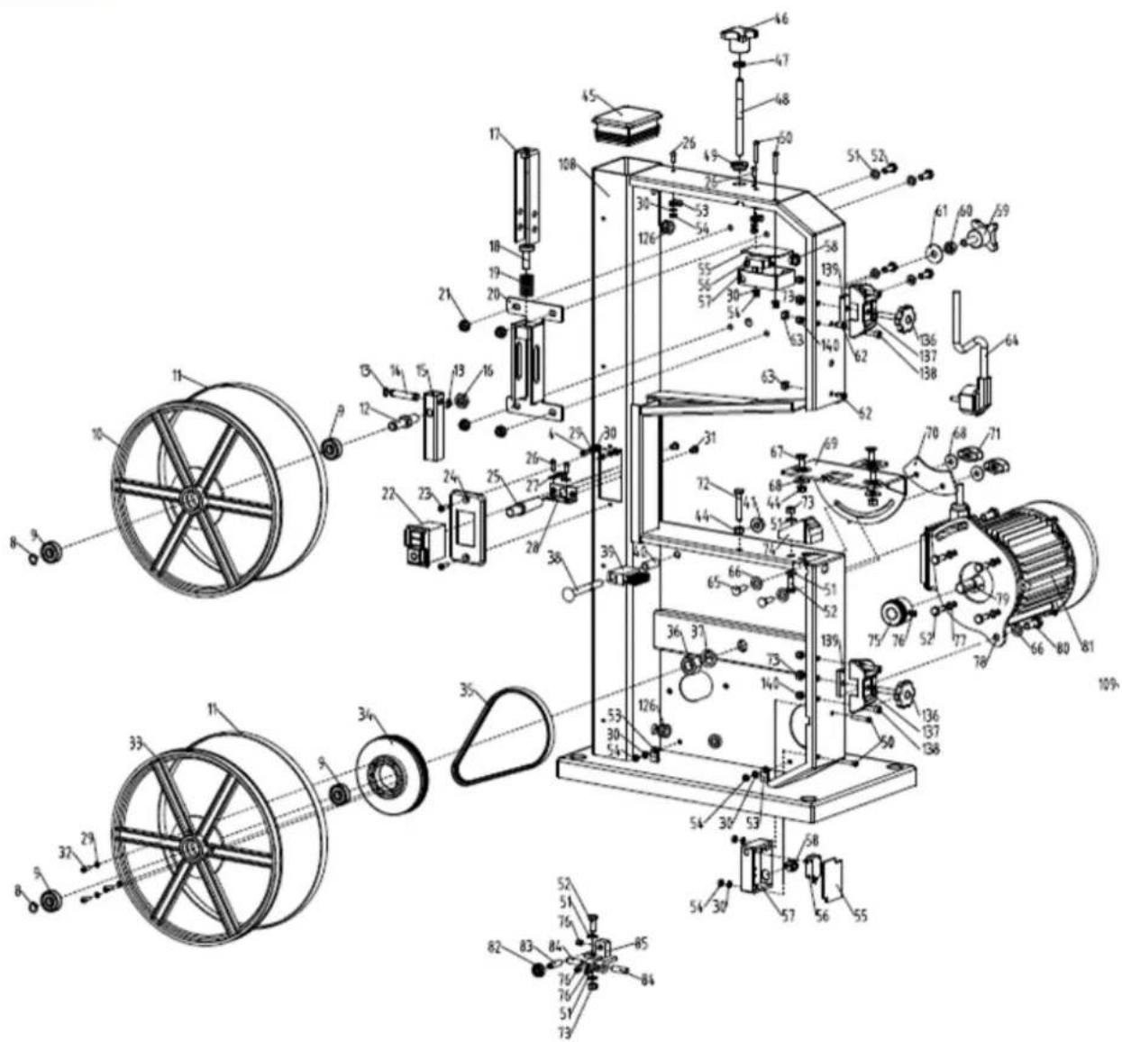
46 ERSATZTEILE / SPARE PARTS / PIEZAS DE RECAMBIO / PIECES DE RECHANGE / REZERVNI DIJELOVI
(EN) With ZIPPER spare parts you use spare parts that are ideally matched to each other. The fitting accuracy of the parts shortens their installation time and increases the service life of the machine.
NOTICE

The installation of parts other than original spare parts leads to the loss of the guarantee! Therefore: When replacing components/parts, only use spare parts recommended by the manufacturer.
Please use the service form at the end of this manual to order spare parts. Always state machine type, spare part number and designation. In order to avoid misunderstandings, we recommend that you enclose a copy of the spare parts drawing with your spare parts order, on which the required spare parts are clearly marked.
You find the order address in the preface of this operation manual.
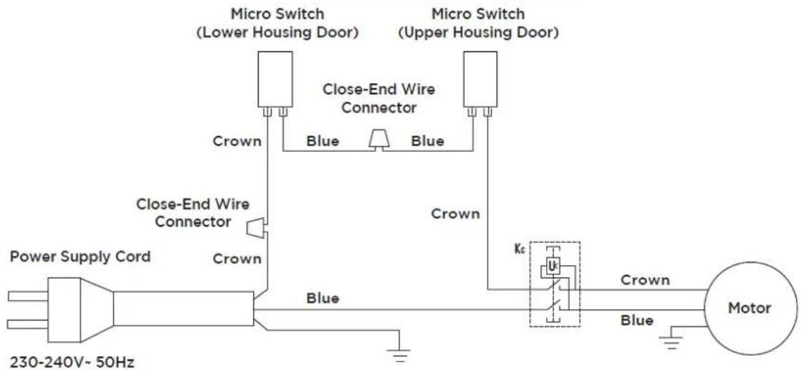
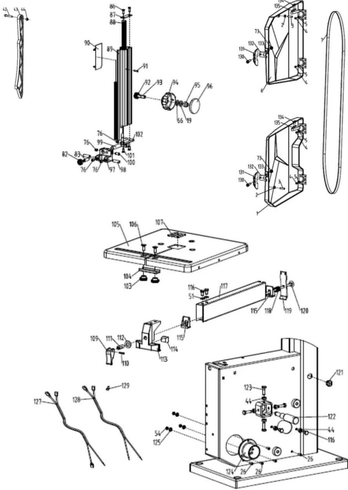
47.1 Spare parts list ZI-BAS205
| No. | Beschreibung / Description | Qty. | No. | Beschreibung / Description | Qty. |
| 1 | Lower Housing Door | 1 | 62 | Wing Cap | 1 |
| 2 | 2Door Locker M6×26 | 2 | 63 | Locking Knob | 3 |
| 3 | Lock Nut M6 | 4 | 64 | Bolt M6×16 | 3 |
| 4 | Screw M5×25 | 2 | 65 | Bench Angle Gauge | 1 |
| 5 | Nut M5 | 2 | 66 | Lock Plate | 1 |
| 6 | Flat Washer 4 | 4 | 67 | Lower Blade Guard | 1 |
| 7 | Screw M4×8 | 6 | 68 | Plug & Power Cord | 1 |
| 8 | Upper Housing Door | 1 | 69 | Motor | 1 |
| 9 | Push Stick | 1 | 70 | Bolt M8×65 | 1 |
| 10 | Screw M6×35 | 1 | 71 | Brush | 1 |
| 11 | Nut M6 | 5 | 72 | Bushing | 1 |
| 12 | Blade | 1 | 73 | Nut M8 | 1 |
| 13 | Circlip for Shaft 10 | 1 | 74 | Bolt M5×10 | 4 |
| 14 | Bearing 6000-2Z | 2 | 75 | Bolt M6×35 | 1 |
| 15 | Circlip for Hole | 1 | 76 | Bolt M6×20 | 2 |
| 16 | Band Saw Wheel-Upper | 1 | 77 | Flat Washer 8 | 2 |
| 17 | Rubber Tyre 2 | 2 | 78 | Table Insert | 1 |
| 18 | Upper Pulley Shaft | 1 | 79 | Work Table | 1 |
| 19 | Circlip for Shaft 8 | 2 | 80 | Bolt M6×20 | 2 |
| 20 | Horizontal Shaft | 1 | 81 | 81 U-Shaped Blocker 1 | 1 |
| 21 | Upper Wheel Shaft Seat | 1 | 82 | Knurled Nut | 2 |
| 22 | Thin Nut M10 | 1 | 83 | Rip Fence Locker | 1 |
| 23 | U-Shaped Bracket | 1 | 84 | Pin 3×16 | 1 |
| 24 | Central Spindle | 1 | 85 | Connecting Bushing | 1 |
| 25 | Wing Spring | 8 | 86 | Flat Washer 10 | 1 |
| 26 | Guide Plate Assembly | 1 | 87 | Rip Fence Holder | 1 |
| 27 | Nut M6 | 4 | 88 | Stop Block | 1 |
| 28 | ON-OFF-Switch | 1 | 89 | Clamping Block | 2 |
| 29 | Screw M4×12 | 2 | 90 | Rip Fence | 1 |
| 30 | Switch Plate | 1 | 91 | Bolt M6×10 | 3 |
| 31 | Cable Sheath | 1 | 92 | Rip Fence Spring | 1 |
| 32 | 32 Cable Fixing Plate | 1 | 93 | Clamping Press Plate | 1 |
| 33 | Cable Pressing Plate | 1 | 94 | Clamping Screw Rod | 1 |
| 34 | Screw M4×10 | 7 | 95 | Suction Connector | 1 |
| 35 | Spring Washer 4 | 2 | 96 | Lock Washer 5 | 3 |
| 36 | Lock Washer 4 | 10 | 97 | Machine Body Weldment | 1 |
| 37 | Bolt M6×12 | 6 | 98 | Circlip 14 | 1 |
| 38 | Spring Washer 6 | 6 | 99 | Sliding Plate | 1 |
| 39 | Big Flat Washer 6 | 6 | 100 | Screw ST3.5×9.5 | 4 |
| 40 | Key 5×14 | 1 | 101 | Dust Cap | 1 |
| 41 | Band Saw Wheel-Lower | 1 | 102 | Rack | 1 |
| 42 | Column Plug | 1 | 103 | Upper Blade Guard | 1 |
| 43 | Setting Knob for Blade Tension | 1 | 104 | Bolt M6×60 | 1 |
| 44 | Thin Nut M8 | 1 | 105 | Gear | 1 |
| 45 | Adjusting Rod | 1 | 106 | Guide Block | 1 |
| 46 | Support Bushing | 1 | 107 | Fixing Rod | 1 |
| 47 | Screw M4×25 | 4 | 108 | Upper Blade Guide Seat | 1 |
| 48 | Microswitch Box Cover | 2 | 109 | Screw M6×6 | 7 |
| 49 | Microswitch | 2 | 110 | Upper Blade Guide | 1 |
| 50 | Microswitch Box | 2 | 111 | Upper Guide Pin | 2 |
| 51 | Nut M4 | 11 | 112 | 112 Bearing Shaft 2 | 2 |
| 52 | Power Cord Buckle | 2 | 113 | Bearing 625-2Z | 2 |
| 53 | Cable Clip | 4 | 114 | Screw M6×12 | 1 |
| 54 | Hood | 2 | 115 | Pin 2.5×12 | 1 |
| 55 | Bolt M6×16 | 6 | 116 | Lower Blade Guide | 1 |
| 56 | Flat Washer 6 | 16 | 117 | Lower Guide Pin | 2 |
| 57 | Big Flat Washer 8 | 1 | 118 | Upper Microswitch Cable | 1 |
| 58 | Nut M8 | 1 | 119 | Lower Microswitch Cable | 1 |
| 59 | Setting Knob for Blade Tracking Adjustment | 1 | 120 | End Wire Connector | 2 |
| 60 | Setting Knob for Blade Guard | 1 | 121 | Cable Gland Strain Relief Connector | 1 |
| 61 | Pressing Spring | 1 |
ZI-BAS250
47.2 Spare parts list ZI-BAS250
| No. | Beschreibung/ Description | Qty. | No. | Beschreibung/ Description | Qty. |
| 1 | Lower Housing Door | 1 | 71 | Lock Knob | 2 |
| 2 | Nut M5 | 2 | 72 | Bolt M6x35 | 1 |
| 3 | Screw M5x25 | 2 | 73 | Locknut M6 | 6 |
| 4 | Screw M4x8 | 6 | 74 | Blade Guard | 1 |
| 5 | Flat Washer 4 | 4 | 75 | Motor Pulley | 1 |
| 6 | Upper Housing Door | 1 | 76 | Screw M6x6 | 8 |
| 7 | Blade | 1 | 77 | Spring Washer 6 | 4 |
| 8 | Shalt Circlip 10 | 2 | 78 | Motor Connecting Plate | 1 |
| 9 | Bearing 6000-2Z | 4 | 79 | Flat Key 5x25 | 1 |
| 10 | Band Saw Wheel-Upper | 1 | 80 | Bolt M8x20 | 2 |
| 11 | Rubber Tyre | 2 | 81 | Motor | 1 |
| 12 | Upper Pulley Shaft | 1 | 82 | Bearing 625-2Z | 2 |
| 13 | Shaft Circlip 8 | 2 | 83 | Bearing Shaft | 2 |
| 14 | Horizontal Shaft | 1 | 84 | Lower Guide Pin | 2 |
| 15 | Upper Wheel Shaft Seat | 1 | 85 | Lower Blade Guide | 1 |
| 16 | Thin Nut M10 | 1 | 86 | Screw ST3.5*9.5 | 2 |
| 17 | U Shaped Bracket | 1 | 87 | Top cover plate for Upper Blade Guard | 1 |
| 18 | Central Spindle | 1 | 88 | Rack | 1 |
| 19 | Wing Spring | 9 | 89 | Upper Blade Guard | 1 |
| 20 | Guide Plate Assembly | 1 | 90 | Sliding Plate | 1 |
| 21 | Nut M6 | 4 | 91 | Pin 2.5x12 | 1 |
| 22 | ON/OFF Switch | 1 | 92 | Gear | 1 |
| 23 | Screw M4x12 | 2 | 93 | Gear Shaft | 1 |
| 24 | Switch Plate | 1 | 94 | Adjusting Knob Seat | 1 |
| 25 | Cable Sheath | 1 | 95 | Locknut M8 | 1 |
| 26 | Screw M4x10 | 7 | 96 | Adjusting Knob Cover | 1 |
| 27 | Cable Pressing Plate | 1 | 97 | Upper Blade Guide | 1 |
| 28 | Cable Fixing Plate | 1 | 98 | Upper Guide Pin | 2 |
| 29 | Spring Washer 4 | 5 | 99 | Fixing Rod | 1 |
| 30 | Lock Washer 4 | 10 | 100 | Screw M6x12 | 1 |
| 31 | Screw M5x10 | 4 | 101 | Screw ST4.2*13 | 2 |
| 32 | Screw M4x16 | 3 | 102 | Upper Blade Guide Seat | 1 |
| 33 | Band Saw Wheel-Lower | 1 | 103 | Locknut | 2 |
| 34 | Pulley-Lower | 1 | 104 | U Shaped Blocker | 1 |
| 35 | Belt | 1 | 105 | Work Table | 1 |
| 36 | Nut M14x1.5 | 1 | 106 | Bolt M6x20 | 2 |
| 37 | Spring Washer 14 | 1 | 107 | Table Insert | 1 |
| 38 | Bolt M8x70 | 1 | 108 | Machine Body Weldment | 1 |
| 39 | Brush | 1 | 109 | Rip Fence Locker | 1 |
| 40 | Bushing | 1 | 110 | Pin 3x16 | 1 |
| 41 | Nut M8 | 1 | 111 | Connecting Bushing | 1 |
| 42 | Screw M6x35 | 1 | 112 | Flat Washer 10 | 1 |
| 43 | Push Stick | 1 | 113 | Rip Fence Holder | 1 |
| 44 | Nut M6 | 15 | 114 | Stop Block | 1 |
| 45 | Column Plug | 1 | 115 | Clamping Block | 2 |
| 46 | Nut M8 | 1 | 116 | Bolt M6x10 | 4 |
| 47 | Thin Nut M8 | 1 | 117 | Rip Fence | 1 |
| 48 | Adjusting Rod | 1 | 118 | Rip Fence Spring | 1 |
| 49 | Support Bushing | 1 | 119 | Clamping Press Plate | 1 |
| 50 | Screw M4x25 | 4 | 120 | Clamping Screw Rod | 1 |
| 51 | Flat Washer 6 | 14 | 121 | Cable Gland Strain Relief Connector | 1 |
| 52 | Bolt M6x16 | 14 | 122 | Lower Pulley Shaft | 1 |
| 53 | Cable Clip | 4 | 123 | Bolt M6x20 | 4 |
| 54 | Nut M4 | 11 | 124 | Suction Connector | 1 |
| 55 | Microswitch Box Cover | 2 | 125 | Lock Washer 5 | 3 |
| 56 | Microswitch | 2 | 126 | Hood | 2 |
| 57 | Microswitch Box | 2 | 127 | Upper Microswitch Cable | 1 |
| 58 | Power Cord Buckle | 2 | 128 | Lower Microswitch Cable | 1 |
| 59 | Knob Bolt M8x25 | 1 | 129 | End Wire Connector | 2 |
| 60 | Nut M8 | 1 | 130 | Screw M6x20 | 2 |
| 61 | Big Flat Washer 8 | 1 | 131 | Inserter Seat | 2 |
| 62 | Screw ST4.2*13 | 2 | 132 | Inserter | 2 |
| 63 | Guide Block | 2 | 133 | Subplate | 2 |
| 64 | Plug& Power Cord | 1 | 134 | Self-plugging Rivet 4x8 | 4 |
| 65 | Bolt M6x20 | 2 | 135 | Leaf-spring | 2 |
| 66 | Flat Washer 8 | 29 | 136 | Knob Bolt M6x32 | 2 |
| 67 | Bolt M6x16 | 3 | 137 | Fixing Seat of Door Locker | 2 |
| 68 | Big Flat Washer 6 | 5 | 138 | Screw M5x16 | 4 |
| 69 | Bench Angle Gauge | 1 | 139 | Inserter | 2 |
| 70 | Lock Plate | 1 | 140 | Locknut M5 | 4 |
Company ZIPPER Maschinen GmbH grants for mechanical and electrical components a warranty period of 2 years for amateur use; and warranty period of 1 year for professional use, starting with the purchase of the final consumer. In case of defects during this period, which are not excluded by paragraph 3, ZIPPER will repair or replace the machine at its own discretion.
2.) Report:
In order to check the legitimacy of warranty claims, the final consumer must contact his dealer. The dealer has to report in written form the occurred defect to ZIPPER. If the warranty claim is legitimate, ZIPPER will pick up the defective machine from the dealer. Returned shippings by dealers which have not been coordinated with ZIPPER, will not be accepted and refused.
3.) Regulations:
a) Warranty claims will only be accepted, when a copy of the original invoice or cash voucher from the trading partner of ZIPPER is enclosed to the machine. The warranty claim expires if the accessories belonging to the machine are missing.
b) The warranty does not include free checking, maintenance, inspection or service works on the machine. Defects due to incorrect usage of the final consumer or his dealer will not be accepted as warranty claims either. Some examples: usage of wrong fuel, frost damages in water tanks, leaving fuel in the tank during the winter, etc.
c) Defects on wear parts are excluded, e.g. carbon brushes, collection bags, knives, cylinders, cutting blades, clutches, sealings, wheels, saw blades, splitting crosses, riving knives, riving knife extensions, hydraulic oils, oil/air/fuel filters, chains, spark plugs, sliding blocks, etc.
d) Also excluded are damages on the machine caused by incorrect or inappropriate usage, if it was used for a purpose which the machine is not supposed to, ignoring the user manual, force majeure, repairs or technical manipulations by not authorized workshops or by the customer himself, usage of non-original ZIPPER spare parts or accessories.
e) After inspection by our qualified personnel, resulted costs (like freight charges) and expenses for not legitimated warranty claims will be charged to the final customer or dealer.
f) In case of defective machines outside the warranty period, we will only repair after advance payment or dealer's invoice according to the cost estimate (incl. freight costs) of ZIPPER.
g) Warranty claims can only be granted for customers of an authorized ZIPPER dealer who directly purchased the machine from ZIPPER. These claims are not transferable in case of multiple sales of the machine.
4.) Claims for compensation and other liabilities:
The liability of company ZIPPER is limited to the value of goods in all cases. Claims for compensation because of poor performance, lacks, damages or loss of earnings due to defects during the warranty period will not be accepted. ZIPPER insists on its right to subsequent improvement of the machine.
51 GARANTÍA (ES)
1.) Garantía:
We monitor the quality of our delivered products in the frame of a Quality Management policy.
Your opinion is essential for further product development and product choice. Please let us know about your:
- Impressions and suggestions for improvement.
- experiences that may be useful for other users and for product design
- Experiences with malfunctions that occur in specific operation modes
We would like to ask you to note down your experiences and observations and send them to us via FAX, E-Mail or by post
Erworben von / purchased from:
E-Mail/ e-mail:
service inquiry spare part inquiry guarantee claim
Please describe amongst others in the problem: What has cause the problem/defect, what was the last activity before you noticed the problem/defect? For electrical problems: Have you had checked you electric supply and the machine already by a certified electrician?
3. Bitte beachten
/ Additional information
INCOMPLETELY FILLED SERVICE FORMS CANNOT BE PROCESSED! FOR GUARANTEE CLAIMS PLEASE ADD A COPY OF YOUR ORIGINAL SALES / DELIVERY RECEIPT OTHERWISE IT CANNOT BE ACCEPTED. FOR SPARE PART ORDERS PLEASE ADD TO THIS SERVICE FORM A COPY OF THE RESPECTIVE EXPLODED DRAWING WITH THE REQUIRED SPARE PARTS BEING MARKED CLEARLY AND UNMISTAKABLE. THIS HELPS US TO IDENTIFY THE REQUIRED SPARE PARTS FASTLY AND ACCEL- LERATES THE HANDLING OF YOUR INQUIRY.


- INHALT /INDEX / ÍNDICE
- TRANSPORT 39
- ASSEMBLY 39
- ADJUSTMENTS 42
- OPERATION 49
- CLEANING, MAINTENANCE, STORGE, DISPOSAL 52
- DISPOSAL 53
- Komponenten / Components / Componentes / Composants / Komponente
- Technische Daten / Technical date / Datos técnicos / Données techniques / Tehnički podaci
- VORWORT (DE)
- Montage des Parallelanschlags
- HINWEIS
- Vorgehensweise:
- Pay special attention to the chapter Safety!
- Copyright
- Customer service contact
- Intended use of the machine
- ZIPPER-MASCHINEN assumes no responsibility or warranty for any other use or use beyond this and for any resulting damage to property or injury.
- Technical Restrictions
- Prohibited Use / Forseeable Misuse
- User Requirements
- Please note that local laws and regulations may determine the minimum age of the operator and restrict the use of this machine!
- Safety Devices
- General safety instructions
- Electrical Safety
- Safety instructions for wood band saws
- Hazard warnings
- DANGER
- WARNING
- CAUTION
- NOTICE
- TRANSPORT
- • Lifting, Depositing:
- - Carrying:
- ASSEMBLY
- Preparatory activities
- Delivery content
- Workplace requirements
- Secure the bandsaw to the floor
- Assembly
- Power Supply
- Connecting to a dust collection system
- NOTE
- ADJUSTMENTS
- Open and close the front doors
- Open the front door:
- Close the front door:
- Selection of saw bands
- Dimensions of the saw bands
- Tensioning/changing the saw blade
- Procedure for exchanging the saw blade:
- Adjusting band saw blade tracking
- Procedure:
- Adjusting the saw band guide
- Adjusting upper saw band guide
- Adjusting lower saw band guide
- Height-adjustment of the blade guard
- Adjusting the tilt of the worktable
- Adjusting the work table at right angles to the saw blade
- Adjusting the saw table lateral alignment
- Adjusting the rip fence
- OPERATION
- Important operating instructions
- Before you start working
- Before each work step
- After work
- Switching On and Off
- Working techniques
- Longitudinal cutting of narrow (thin) workpieces
- Diagonal cut
- Cutting tenons
- Cutting wedges
- Cutting Curves
- Cutting with a template, handling shaped work
- Cutting circular work
- Fixtures
- CLEANING, MAINTENANCE, STORGE, DISPOSAL
- Cleaning
- Maintenance
- Replacement of the V-belt (only for ZI-BAS250)
- Loose V-Belt tension
- Change the V- belt
- Tension the V- belt
- Replacement of the table insert
- DISPOSAL
- TROUBLESHOOTING
- PRÓLOGO (ES)
- iEstimado cliente!:
- AVISO
- Procedimiento:
- Cortes en curva
- Cher client, chère cliente,
- Restrictions techniques
- Procédure :
- Montaža kopče
- Montaža štapa za guranje
- Montaža paralelnog graničnika
- Postupak:
- Bočni vodeći ležaj
- Donja vodilica trake za piljenje
- Rezanje klinova
- Šablone / oblikovani dijelovi
- ERSATZTEILE / SPARE PARTS / PIEZAS DE RECAMBIO / PIECES DE RECHANGE / REZERVNI DIJELOVI
- 2.) Report:
- 3.) Regulations:
- 4.) Claims for compensation and other liabilities:
- GARANTÍA (ES)
- 1.) Garantía:
- Bitte beachten
- / Additional information
Brand : Zipper
Model : ZIBAS205
Category : Saw