
ZI-KGS255DS - Saw Zipper - Free user manual and instructions
Find the device manual for free ZI-KGS255DS Zipper in PDF.


| Product Type | Miter Saw |
| Brand | Zipper |
| Model | ZI-KGS255DS |
| Power Supply | 230V / 50Hz |
| Motor Power | 1800 W |
| Blade Diameter | 255 mm |
| No-Load Speed | 4500 rpm |
| Weight | 12 kg |
| Dimensions (L x W x H) | 510 x 420 x 380 mm |
| Cutting Capacity (90°) | 170 x 60 mm |
| Cutting Capacity (45° bevel) | 170 x 40 mm |
| Bevel Range | 0° - 45° left |
| Miter Range | 0° - 45° left / right |
| Dust Extraction Port | 36 mm diameter |
| Laser Guide | Yes, integrated |
| Safety Features | Electric brake, spindle lock, blade guard |
| Cleanning | Wipe with dry cloth, clean dust ports regularly |
| Spare Parts Availability | Authorized Zipper service centers |
| Certification | CE |
Frequently Asked Questions - ZI-KGS255DS Zipper
User questions about ZI-KGS255DS Zipper
0 question about this device. Answer the ones you know or ask your own.
Ask a new question about this device
Download the instructions for your Saw in PDF format for free! Find your manual ZI-KGS255DS - Zipper and take your electronic device back in hand. On this page are published all the documents necessary for the use of your device. ZI-KGS255DS by Zipper.
USER MANUAL ZI-KGS255DS Zipper
CE
ZI-KGS255DS
EAN: 9120039234052

1 INHALT / INDEX
1 INHALT / INDEX 2
2 SICHERHEITSZEICHEN / SAFETY SIGNS / SEÑALES DE SEGURIDAD / ZNAKOVI ZA SIGURNOST 6
12.1 Intended Use of the Machine.... 26
12.1.1 Technical Restrictions 26
12.1.2 Prohibited Use / Forseeable Misuse....26
12.2 User Requirements.... 26
12.3 Safety Devices 27
12.4 General Safety Instructions.... 27
12.5 Electrical Safety 28
12.6 Special Safety Instructions for Woodworking machines 28
12.7 Hazard Warnings 29
13 TRANSPORT 30
14 ASSEMBLY 30
14.1 Checking Scope of Supply 30
14.2 The workplace 30
14.3 Assembling the machine.... 30
15 OPERATION 30
15.1 Initial check before start 30
15.2 Operation 31
15.2.1 Locking / unlocking the machine head in the transport position....31
15.2.2 Setting the angular position of the worktable....31
15.2.3 Setting the angular position of the machine head 31
15.2.4 Setting the stops/fences. 32
15.2.5 Setting saw blade speed 32
15.2.6 Setting cutting depth limiting....32
15.2.7 Connection to a dust collection system....32
15.2.8 Switch machine ON-OFF 32
15.3 Operation modes 33
15.3.1 Mitre cuts....33
15.3.2 Sliding cuts 33
15.3.3 Slot cuts 34
16 CLEANING, MAINTENANCE, STORAGE, DISPOSAL 34
16.1 Cleaning 34
16.2 Maintenance 34
16.2.1 Maintenance schedule....34
16.2.2 Adjusting the angular position (by means of stop angle) 35
16.2.3 Saw blade change 36
16.2.4 Setting the Laser 36
16.2.5 Emptying/changing the chip bag 37
16.2.6 Checking / changing carbon brusher....37
16.2.7 Exchange table insert 37
16.3 Storage.... 37
16.4 Disposal.... 38
17 TROUBLESHOOTING 38
18 PRÓLOGO (ES) 39
19 SEGURIDAD 40
READ THE MANUAL! Read these operating instructions carefully and familiarize yourself well with the operating elements of your machine in order to be able to operate and maintain it properly and thus prevent damage to man and machine.
EN Switch off the machine before maintenance and breaks and pull out the mains plug!
EN Personal Protection Equipment
EN Warning of sharp objects!
ES iAdvertencia frente a objetos puntiagudos! Upozorenje na šiljaste predmete!



HR

DE Achtung Laserstrahlung, Nicht in den Strahl blicken! EN Attention Laser light, Do not look into the beam! ES Atención radiación láser. ¡No mire el rayo! HR Pozor, lasersko zračenje, ne gledajte u zraku!
EN Missing or non-readable security stickers have to be replaced immediately!
| ZI-KGS255DS | |||
| 1 | Feststellschraube Maschinenkopfschwenkung / fixation screw machine head-tilt / Tornillo de fijación de la inclinación del cabezal de la máquina / Pričvrsni vijak za naginjanje glave stroja | 20 | Beweglicher Sägeblattschutz / moveable saw blade guard / Protección móvil de la hoja de la sierra / Pomična zaštita lista pile |
| 2 | Neigungsbegrenzung / tilt protection / Tope de inclinación / Graničnik nagiba | 21 | Absauganschluss / Dust collection port / Conexión del sistema de aspiración / Odsisni priključak |
| 3 | Feststellschraube Tischverlängerung / n screw table extension / Tornillo de fijación extensión de la mesa / Pričvrsni vijak žetka stola | 22 | Schnittiefeneinstellschraube / screw for cutting depth limiting / Tornillo de ajuste de la profundidad de corte / Vijak za postavljanje dubine reza |
| 4 | Tischverlängerung / table extension / Extensión de la mesa / Produžetak stola | 22-01 | Anschlag Schnittiefeneinstellung / stop for cutting depth limiting / Tope del ajuste de la profundidad de corte / Graničnik za podešavanje dubine reza |
| 5 | Skala Winkeleinstellung Tisch / scale for table angle adjustment / Escala del ajuste angular de la mesa / Skala za podešavanje nagiba stola | 23 | Fixierschraube Zugeinrichtung / fixation screw sliding mechanism / Tornillo de fijación del dispositivo deslizante / Vijak za fiksiranje vlačne naprave |
| 6 | Fixierhebel Winkeleinstellung Tisch / fixation lever angle adjustment table / Palanca de fijación del ajuste angular de la mesa / Poluga za fiksiranje nagiba stola | 24 | Fixierschraube Anschlag / fixation screw fence / Tornillo de fijación del tope / Vijak za fiksiranje graničnika |
| 7 | Entriegelungshebel für Winkeleinstellung Tisch / position angle adjustment lever / Palanca de desbloqueo del ajuste angular de la mesa / Ručica za deblokiranje nagiba stola | 25 | Justierschraube 90° Schnitt / adjusting screw 90° cut / Tornillo de ajuste del corte de 90° / Vijak za podešavanje reza od 90° |
| 8 | Einstellschraube Tischabstützung / adjusting screw table support / Tornillo de ajuste del soporte de la mesa / Vijak za podešavanje postolja stola | 26 | Justierschraube 45° Schnitt / adjusting screw 45° cut / Tornillo de ajuste del corte de 45° / Vijak za podešavanje reza od 45° |
| 9 | Anschlag / fence / Tope / Graničnik | 27 | Zugeinrichtung / sliding mechanism / Dispositivo deslizante / Vlačna naprava |
| 9-1 | Anschlag (Einstellbar) / fence (adjustable) / Tope (ajustable) / Graničnik (podesiv) | 28 | Wahlschalter Sägeblattdrehzahl / Saw blade speed selector switch / Interruptor selector de velocidad de la hoja de la sierra / Prekidač za izbor broja okretaja lista pile |
| 10 | Zeiger Maschinenkopfschwenkwinkel / pointer machine head angle adjustment / Indicador del ángulo de inclinación del cabezal de la máquina / Pokazivač kuta nagiba glave stroja | 29 | EIN-AUS-Schalter Laser / ON-OFF-switch laser / Interruptor ON/OFF del láser / Prekidač za uključivanje/isključivanje lasera |
| 10-1 | Skala Maschinenkopfschwenkwinkel / scale machine head angle adjustment / Escala del ángulo de inclinación del cabezal de la máquina Skala kuta nagiba glave stroja | 30 | Befestigungsflansch Sägeblatt / outer fixation flange saw-blade / Brida de fijación de la hoja de la sierra / Pričvrsna prirubnica lista pile |
| 11 | Verriegelungsknopf Transportstellung / locking bolt transport position / Botón de bloqueo de la posición de transporte / Gumb za fiksiranje transportnog položaja | 31 | Flanschschraube Sägeblatt / flange screw saw-blade / Tornillo de la brida de la hoja de la sierra / Prirubnički vijak lista pile |
| 12 | Motor / motor / Motor / Motor | 32 | Schwenkbarer Tisch / rotary table / Mesa giratoria / Zakretni stol |
| 13 | Abeckung Kohlebürsten / cover carbon brush / Cubierta de escobillas de carbón / Poklopac ugljenih četki | 33 | Zeiger Winkellage Maschinenkopf / pointer angle adjustment machine head / Indicador posición angular del cabezal de la máquina / Pokazivač kuta nagiba glave stroja |
| 14 | Handgriff / handle / Mango / Drška | 34 | Maschinenkopf / machine head / Cabezal de la máquina / Glava stroja |
| 15 | Verriegelungsknopf START / lock switch start / Botón de bloqueo de ARRANQUE / Gumb za fiksiranje START | 35 | Sägeblatt / saw blade / Hoja de la sierra / List pile |
| 16 | EIN-AUS-Schalter Säge / ON-OFF-Switch saw / Interruptor ON/OFF de la sierra / Prekidač za uključivanje/isključivanje pile | 36 | Sägewellen-Verriegelung (Sägeblatttausch) / saw shaft lock (saw blade change) / Dispositivo de bloqueo del eje de la sierra (sustitución de la hoja de la sierra) / Mehanizam za blokiranje vratila pile (zamjena lista pile) |
| 17 | Laser / laser / Láser / Laser | 37 | Sägetisch (Fixteil) / fixed saw table / Mesa de la sierra (componente fijo) / Stol pile (nepomični dio) |
| 18 | Spanvorrichtung / clamping device / Dispositivo de sujeción / Zatezna naprava | 38 | Spänefangsack / chip collection bag** / Bolsa colectora de virutas** / Vreća za piljevinu** |
| 19 | Tischeinlage / table insert / Suplemento de la mesa / Uložak za stol | **nicht abgebildet / not shown / no representada / nije prikazano | |
3.3 Technische Daten / technical data / Datos técnicos / Tehnički podaci
| ZI-KGS255DS | |
| Spannung / Voltage / Tensión / Napon | 220-240 V / 50 Hz |
| Motorleistung / motor power / Potencia del motor / Snaga motora | 2000 W |
| Leerlaufdrehzahl Sägeblatt (1;2-Gang) / no-load speed (1;2 gear) / Velocidad de ralentí de la hoja de la sierra (1;2 marchas)Broj okretaja u praznom hodu, list pile (1;2 stupanj prijenosa) | 3200 min-1 (I) ; 4500 min-1 (II) |
| Schutzklasse / appliance class / Clase de protección / Klasa zaštite | II |
| Schutzart / protection class / Grado de protección / Vrsta zaštite | IP 20 |
| Sägeblattdurchmesser / saw blade diameter / Diámetro de la hoja de la sierra / Promjer lista pile | ∅ 255 mm |
| Bohrungdurchmesser Sägeblatt / saw blade bore diameter / Diámetro del orificio de la hoja de la sierra / Promjer otvora lista pile | ∅ 30 mm |
| Max. Zahnbreite des Sägeblattes / max. tooth width of the saw blade / Max. Ancho de los dientes de la hoja de sierra / Maks. Širina zupca lista pile | 3 mm |
| Arbeitstisch Schwenkwinkel / work table tilting angle / Ángulo de inclinación de la mesa de trabajo / Kut zakretanja radnog stola | ± 45 ° |
| Sägeaggregat Schwenkwinkel / saw unit tilting angle / Ángulo de inclinación del grupo de la sierra / Kut zakretanja agregata pile | + 45 ° |
| Schnittleistung / cutting capacity / Potencia de corte Kapacitet rezanja 90° / 90° | 340 x 90 mm |
| Schnittleistung / cutting capacity / Potencia de corte / Kapacitet rezanja 90° / 45° | 240 x 90 mm |
| Schnittleistung / cutting capacity / Potencia de corte / Kapacitet rezanja 45° / 90° | 340 x 45 mm |
| Schnittleistung / cutting capacity / Potencia de corte / Kapacitet rezanja 45° / 45° | 240 x 45 mm |
| Anschlagdimension / fence dimension (L x H) / Dimensiones del tope (L x H) / Dimenzija graničnika (D x V) | 218 x 54 mm |
| Verpackungsmaße / packaging dimension / Dimensiones del embalaje / Dimenzije ambalaže | 815 x 480 x 370 mm |
| Maschinenmaße (L x B (mit Verlängerung) x H) /machine dimension (L x W (with extension) x H) / Dimensiones de la máquina (L x A (con extensión) x H) / Dimenzije stroja (D x Š (s produžetkom) x V) | 780 x 450 (700) x 585 mm |
| Absauganschlussdurchmesser / dust collection port diameter / Diámetro de la conexión del sistema de aspiración / Promjer priključka za odsis | 43 mm |
| Anschlusskabellänge / cable length / Longitud del cable de conexión / Dužina priključnog kabela | 2 m |
| Schalldruckpegel / livello di pressione sonora / Nivel de presión sonora / Razina zvučnog tlaka LPA | 97,2dB(A)K:3dB(A) |
| Schallleistungspegel / livello di potenza del suono / Nivel de potencia acústica / Razina zvučne snage LWA | 110,2dB(A)K:3dB(Å) |
| Gewicht (Netto) / weight (net) / Peso (neto) / Težina (neto) | 14,6 kg |
| Gewicht (Brutto) / weight (gross) / Peso (bruto) / Težina (bruto) | 18,2 kg |
| Laser | |
| Laser class / Clase de láser / Laser class | Class II |
| Norm / Standard / Norma / Norm | EN 60825-1:2014 |
| Laserwellenlänge / wavelength of laser / Longitud de onda del láser / Valna dužina lasera | 650nm |
| Laserleistung / laser output / Potencia del láser / Snaga lasera | < 1 mW |
(DE) Hinweis Geräuschangaben: Die angegebenen Werte sind Emissionswerte und müssen damit nicht zugleich auch sichere Arbeitsplatzwerte darstellen. Obwohl es eine Korrelation zwischen Emissions- und Immissionspegeln gibt, kann daraus nicht zuverlässig abgeleitet werden, ob zusätzliche Vorsichtsmaßnahmen notwendig sind oder nicht. Faktoren, welche den am Arbeitsplatz tatsächlich vorhandenen Immissionspegel beeinflussen, beinhalten die Eigenart des Arbeitsraumes und andere Geräuschquellen, d. h. die Zahl der Maschinen und anderer benachbarter Arbeitsvorgänge. Die zulässigen Arbeitsplatzwerte können ebenso von Land zu Land variieren. Diese Information soll jedoch den Anwender befähigen, eine bessere Abschätzung von Gefährdung und Risiko vorzunehmen.
(EN) Notice noise emission: The values given are emission values and therefore do not have to represent safe workplace values at the same time. Although there is a correlation between emission and immission levels, it cannot be reliably deduced whether additional precautions are necessary or not. Factors influencing the actual immission level at the workplace include the nature of the workspace and other noise sources, i.e. the number of machines and other adjacent operations. The permissible workplace values may also vary from country to country. However, this information should enable the user to make a better assessment of hazard and risk.
(ES) Aviso sobre los valores de ruido: Los valores indicados son valores de emisión y, por lo tanto, no representan necesariamente al mismo tiempo valores seguros en el lugar de trabajo. Aunque hay una correlación entre los niveles de emisión y los de inmisión, no se puede deducir con certeza si es necesario adoptar medidas de precaución adicionales o no. Entre los factores que influyen en el nivel de inmisión real en el lugar de trabajo, se encuentran la naturaleza del espacio de trabajo y otras fuentes de ruido, es decir, el número de máquinas y otros procesos de trabajo adyacentes. Asimismo, los valores admisibles en el lugar de trabajo pueden variar de un país a otro. No obstante, esta información debe capacitar al usuario a evaluar mejor los peligros y los riesgos.
(HR) Napomena o emisiji buke: navedene vrijednosti su vrijednosti emisije i ne moraju istovremeno predstavljati i sigurne vrijednosti na radnom mjestu. Iako postoji korelacija između razina emisije i imisije, iz toga se ne može pouzdano zaključiti jesu li ili nisu potrebne dodatne mjere opreza. Čimbenici koji utječu na stvarnu razinu imisije na radnom mjestu obuhvaćaju specifičnost radnog prostora i druge izvore buke, tj. broj strojeva i drugih radnih procesa u blizini. Dopuštene vrijednosti na radnom mjestu mogu se razlikovati i u različitim državama. Ali ove bi informacije korisniku trebale omogučiti da izvrši procjenu opasnosti i rizika.
4 VORWORT (DE)
This manual contains information and important instructions for the installation and correct use of the miter saw ZI-KGS255DS.
Following the usual commercial name of the device (see cover) is substituted in this manual with the name "machine".

This manual is part of the product and shall not be stored separately from the product. Save it for later reference and if you let other people use the product, add this instruction manual to the product.
Please read and obey the security instructions!
Due to constant advancements in product design, construction pictures and content may diverse slightly. However, if you discover any errors, inform us please.
Technical specifications are subject to changes!
Please check the product contents immediately after receipt for any eventual transport damage or missing parts.
Claims from transport damage or missing parts must be placed immediately after initial product receipt and unpacking before putting the product into operation.
Please understand that later claims cannot be accepted anymore.
Copyright
© 2018
This document is protected by international copyright law. Any unauthorized duplication, translation or use of pictures, illustrations or text of this manual will be pursued by law.
Court of jurisdiction is the regional court Linz or the competent court for 4707 Schlüsslberg, AUSTRIA.
Customer service contact
This section contains information and important notes on safe commissioning and handling of the machine.

For your personal safety, please read these operating instructions carefully before commissioning. This will enable you to handle the machine safely and prevent misunderstandings as well as personal injury and damage to property. Also observe the symbols and pictograms used on the machine as well as the safety and danger information!
12.1 Intended Use of the Machine
The machine is intended exclusively for the following activities:
Cross-cut and mitre cutting of wood and materials with similar physical properties to wood within the specified technical limits.
ZIPPER-MASCHINEN assumes no responsibility or warranty for any other use or use beyond this and for any resulting damage to property or injury.
12.1.1 Technical Restrictions
The machine is intended for use under the following ambient conditions:
Rel. Humidity: max. 65 %
Temperature (operational) +5°C bis +40°C
Temperature (Storage, Transport) -20°C bis +55°C
12.1.2 Prohibited Use / Forseeable Misuse
- Operation of the machine without adequate physical and mental aptitude
- Operating the machine without knowledge of the operating instructions
- Changes in the design of the machine
- Operating the machine in a potentially explosive environment (machine can generate ignition sparks during operation)
- Operation of the machine in closed rooms without chip and dust extraction (a normal household vacuum cleaner is not suitable as an extraction device).
- Operating the machine outside the limits specified in this manual
- Remove the safety markings attached to the machine.
- Modify, circumvent or disable the safety devices of the machine.
- Cutting of materials with dimensions outside the limits specified in this manual
- Use of tools which do not meet the safety requirements of the standard for machine tools for woodworking (EN847-1).
The improper use or disregard of the versions and instructions described in this manual will result in the voiding of all warranty and compensation claims against Holzmann Maschinen GmbH.
12.2 User Requirements
The physical and mental suitability as well as knowledge and understanding of the operating instructions are prerequisites for operating the machine. Persons who, because of their physical, sensory or mental abilities or their inexperience or ignorance, are unable to operate the machinery safely must not use it without the supervision or instruction by a responsible person.
Please note that local laws and regulations may stipulate the minimum age of the operator and restrict the use of this machine!
Put on your personal protective equipment before working on the machine.
Work on electrical components or equipment may only be carried out by a qualified electrician or under the instruction and supervision of a qualified electrician.
12.3 Safety Devices
The machine is equipped with the following safety devices:
| Safety guard, saw blade protection | |
 | Clamping device and stop/fence |
12.4 General Safety Instructions
To avoid malfunctions, damage and health hazards when working with the machine, in addition to the general rules for safe working, the following points must be observed:
• Before commissioning, check the machine for completeness and function.
- Choose a level, vibration-free, non-slip surface for the installation location.
- Ensure sufficient space around the machine!
- Ensure sufficient lighting conditions at the workplace to avoid stroboscopic effects!
- Only use perfect tools that are free of cracks and other defects (e.g. deformations).
- Remove setting tools from the machine before switching on.
- Keep the area around the machine free of obstacles (e.g. dust, chips, cut workpiece parts etc.).
- Check the strength of the machine connections before each use.
- Never leave the running machine unattended. If necessary, stop the machine before leaving.
- The machine may only be operated, serviced or repaired by persons who are familiar with it and who have been informed of the dangers arising in the course of this work.
- Ensure that unauthorised persons maintain an appropriate safety distance from the machine and, in particular, keep children away from the machine..
- Wear suitable protective equipment (eye protection, dust mask, respiratory protection, ear protection, gloves when handling tools) as well as close-fitting work protective clothing - never wear loose clothing, ties, jewellery, etc. - danger of being drawn in!
• Work with gloves on rotating parts is not permitted!
- Hide long hair under hair protection.
- Do not remove any sections or other parts of the workpiece from the cutting area while the machine is running!
- Do not remove splinters and chips by hand! Use a sliding stick for this purpose!
• Always work with care and the necessary caution and never use excessive force.
- Do not overload the machine!
- Do not work on the machine if you are tired, not concentrated or under the influence of medication, alcohol or drugs!
- Do not use the machine in areas where vapours from paints, solvents or flammable liquids represent a potential danger (danger of fire or explosion!).
- Do not smoke in the immediate vicinity of the machine (fire hazard)!
- Make sure that the ON/OFF switch is in the "OFF" position before connecting the machine to the power source.
- Do not use the machine if it cannot be switched on and off with the ON/OFF switch.
• Make sure that the device is earthed.
- Only use suitable extension cords.
- Always shut down the machine before carrying out any conversion, adjustment, measuring, cleaning, maintenance or repair work and always disconnect it from the power supply for
maintenance or repair work. Before starting any work on the machine, wait until all tools or machine parts have come to a complete standstill and secure the machine against unintentional restarting.
12.5 Electrical Safety
- Only use suitable extension cords. (cross-section 1.5mm2 for length up to 25m; H05VV-F)
- A damaged or tangled cable increases the risk of electric shock. Handle the cable with care. Never use the cable to carry, pull or disconnect the power tool. Keep the cable away from heat, oil, sharp edges or moving parts.
- Proper plugs and sockets reduce the risk of electric shock.
- Water entry into machine increases the risk of electric shock. Do not expose machine to rain or moisture.
- The machine may only be used in humid environments if the power source is protected by a residual current circuit breaker.
- Do not use the power tool if it cannot be turned on and off with the ON/OFF switch.
- Avoid contact of the body with grounded surfaces such as pipes, radiators, ovens and refrigerators. There is an increased risk of electric shock if the body is earthed.
12.6 Special Safety Instructions for Woodworking machines
- Work with gloves on rotating parts is not permitted!
- During operation of the machine wood dust is generated. Therefore, connect the machine to a suitable dust collection system for dust and chips during installation!
• Always switch on the dust collection system before you start machining the workpiece! - Never remove sections or other parts of the workpiece from the cutting area while the machine is running.
- When using milling tools with a diameter of ≥ 16 mm and circular saw blades, these must comply with EN 847-1:2013 and EN 847-2:2013; tool carriers must comply with EN 847-3:2013;
- Excessive noise can cause hearing damage and temporary or permanent hearing loss. Wear hearing protection certified to health and safety regulations to limit noise exposure.
- Replace cracked and deformed saw blades immediately, they cannot be repaired.
- Use clean and sharpened saw blades, which are less sensitive to malfunctions and easier to guide.
- If possible, use clamps to hold/fix the workpiece. If you hold the workpiece by hand, always hold your hand at least 100 mm from both sides of the saw blade. Do not use this saw to cut parts that are too small to be securely clamped or held by hand.
- Never cross the intended cutting line in front of or behind the saw blade.
- Check your workpiece before cutting. If the workpiece is bent or warped, clamp it with the outside bent surface against the stop. Always make sure that there is no gap between the workpiece, stop and table along the cutting line. Bent or warped workpieces can twist or move and can cause jamming of the circular saw blade during cutting. There must also be no nails or foreign objects in the workpiece.
- Cut only one workpiece at the same time.
- Whenever you change the mitre angle setting, make sure that the adjustable stop for supporting the workpiece is set correctly and does not disturb the saw blade or the protective system. Without switching the machine "ON", check without moving the workpiece by moving the saw blade (completely simulated cut) that there are no disturbances or dangers when cutting at the stop.
- For a workpiece that is wider or longer than the supporting table, sufficient support such as table extensions, saw blocks, etc. must be provided.
- Always use a clamp or fixture designed to accept round material such as rods or tubes properly.
- Allow the saw blade to reach full speed before touching the workpiece.
-
If the workpiece or saw blades become jammed, turn off the mitre saw immediately. Wait until all moving parts have come to a standstill and disconnect the plug from the power source, then start removing the jammed material.
-
After you have finished cutting, release the switch, hold the machine head down and wait for the blade to stop before removing the cut part.
- Hold the handle firmly if you make an incomplete cut or release the switch before the machine head is fully in the down position.
Instructions for the use of the LASER:
- Do not look directly into the laser beam with unprotected eyes.
- Never point the laser beam at reflective surfaces or persons or animals. Even a low-power laser beam can cause eye damage.
- Never open the laser module. Unexpected exposure to the beam may occur.
- Do not replace the laser with another type of laser.
- Repairs to the laser may only be carried out by the laser manufacturer or an authorized representative.
12.7 Hazard Warnings
Despite their intended use, certain residual risks remain. Due to the structure and construction of the machine, hazardous situations may occur when handling the machines:
| DANGER | |
| A safety instruction designed in this way indicates an imminently hazardous situation which, if not avoided, will result in death or serious injury. | |
| WARNING | |
| Such a safety instruction indicates a potentially hazardous situation which, if not avoided, may result in serious injury or even death.. | |
| CAUTION | |
| A safety instruction designed in this way indicates a potentially hazardous situation which, if not avoided, may result in minor or moderate injury. | |
| NOTICE | |
| A safety notice designed in this way indicates a potentially hazardous situation which, if not avoided, may result in property damage. | |
Irrespective of all safety regulations, their sound common sense and corresponding technical suitability/training are and remain the most important safety factor in the error-free operation of the machine. Safe working depends first and foremost on you!
13 TRANSPORT
For proper transport, follow the instructions and information on the transport packaging regarding centre of gravity, attachment points, weight, means of transport to be used and prescribed transport position, etc.
Transport the machine in its packaging to the place of installation. When lifting, carrying and depositing the load, make sure that you are in the correct posture:
• Lifting, Depositing
Ensure stability when lifting / setting down (legs hip width).
Lift / lower load with bent knees and straight back (like weightlifter).
Do not lift / lower the load jerkily.
- Carrying
Carry load with both hands as close to body as possible.
Carry load with straight back.
14 ASSEMBLY
14.1 Checking Scope of Supply
Check the machine immediately after delivery for transport damage and missing parts.
14.2 The workplace
Choose a suitable place for the machine.
Pay attention to the safety requirements and the dimensions of the machine.
The selected location must ensure a suitable connection to the electrical supply as well as the possibility of connection to an extraction system. Make sure that the floor can support the load of the machine. The machine must be levelled simultaneously at all support points. It is also necessary to guarantee a distance of at least 0.8 m around the machine. The necessary distance must be provided for the feeding of long workpieces.
14.3 Assembling the machine
The machine is pre-assembled. Following assembly-steps are necessary:
 | Pull out the pre-assembled tilt-protection (A) completely and secure it with the Allen screw (S). |
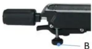
 | Adjust the adjusting screw (B) to the level of the table top to avoid wobbling of the machine. |
15 OPERATION
15.1 Initial check before start
- Check that the speed of the machine is lower than the max. permissible speed of the saw blade used.
- Check saw blade rotation and saw blade dimensions to match the machine.
- Check that the saw blade guard works properly.
- Check whether the connection to a dust collection system is installed.
- Check whether the stops/fences are set correctly and the saw blade is tightened.
- Check whether the machine is fixed on the working plate or a machine stand.
15.2 Operation
15.2.1 Locking / unlocking the machine head in the transport position
By slightly pressing down the machine head (34) and simultaneously removing the locking bolt (11) from the motor holder, the saw is released from the lowest /transport position.
Note: Please hold the handle and guide the machine head slowly upwards until it reaches the uppermost position. If the handle is released, the machine head will jump up due to the spring preload. Press the machine head (34) downwards to engage and reattach the locking bolt (11).
15.2.2 Setting the angular position of the worktable
| Release the locking lever (6) when it is tightened, pull the locked position lever (7) upwards and adjust the rotary table (32) with the locking lever (6) to the desired angle. The angular position is indicated by a pointer (33) on the turntable. Return the locking lever (6) to the closed position to secure the rotary table (32). |
15.2.3 Setting the angular position of the machine head
| 14 34 10 1 1 | Loosen the fixing screw (1). Turn the machine head (34) with the handle (14) to the left until desired angle value on the scale (10) is reached. Then tighten the fixing screw (1) again. |
15.2.4 Setting the stops/fences.

The two adjustable stops (9-1) must be adjusted after changing the machine head angle (90-45°). Loosen the fixing screws (24) and adjust the stops so that there is a distance of 8-10 mm between the saw blade and the stop. Then retighten the fixing screws (24) to fix the stops (9-1).
CAUTION

Before cutting, check that the stop bars and the saw blade cannot collide. (simulated cut with switch-off machine)
15.2.5 Setting saw blade speed

Set the selector switch (28) to the desired speed.
Pos I : 3200 min-1
Pos II: 4500 min-1
15.2.6 Setting cutting depth limiting
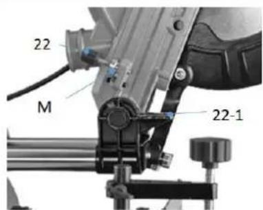
The cutting depth can be adjusted continuously with the screw (22). To do this, loosen the thumb nut (M) on the screw (22). Turn the screw (22) in or out to set the desired cutting depth. Then tighten the thumb nut (M) again.
NOTE

Check the setting by performing a test cut.
15.2.7 Connection to a dust collection system
For dust extraction in closed rooms, connect a suction hose to the dust extraction nozzle and fix it with a hose clamp. Connection dimensions according to technical data.
15.2.8 Switch machine ON-OFF

Switch machine ON: Press the lock switch (15) and press the ON/OFF switch (16) on the handle.
Switch the machine OFF: Release the ON-OFF switch (16).
15.3 Operation modes
15.3.1 Mitre cuts
Mitre are particularly suitable for cutting small workpieces (approx. 100 mm) to length.
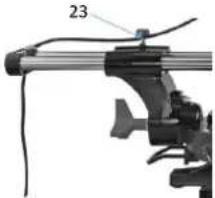
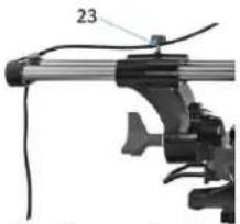
- For cross-cut cuts, the sliding mechanism is fixed by the fixation screw (23) so that the saw unit cannot slide forwards or backwards during the cut.
- Adjust the angle setting according to the desired operation and adjust the stops/fences accordingly.
- Mark the cutting line (by laser).
- Place workpiece against stop/fence and table and fix with the clamp device.
- Move the machine head to the uppermost position.
- Switch on the machine and wait until the saw blade has reached full speed (approx. 5 sec.),
■ Make the crosscut (move the machine head downwards) until it has reached the lowest position. - Move the machine head to the uppermost position.
NOTE

Machine head is spring loaded, do not simply release the machine head, instead move the handle upwards until the uppermost position is reached (rest position).
■ Release the ON-OFF switch and wait until saw blade comes to stand still.
■ Remove workpiece
15.3.2 Sliding cuts
Sliding cuts are suitable for cutting longer workpieces.
- For that kind of cuts, the sliding mechanism is unlocked by releasing the fixation screw (23) so that the saw unit can slide forwards or backwards during the cut.

- Adjust the angle setting according to the desired operation and adjust the stops/fences accordingly.
■ Mark the cutting line (by laser). - Place workpiece against stop/fence and table and fix with the clamp device.
- Move the machine head to its uppermost position and pull the machine head towards you.
- Switch on the machine and wait until the saw blade has reached full speed (approx. 5 sec.),
- Make the cut (move the machine head downwards) until it has reached the lowest position and then slowly push the machine head backwards to be able to machine the wide workpiece over its entire length.
- Move the machine head to the uppermost position.
NOTE

Machine head is spring loaded, do not simply release the machine head, instead move the handle upwards until the uppermost position is reached (rest position).
- Release the ON-OFF switch and wait until saw blade comes to stand still.
■ Remove workpiece
15.3.3 Slot cuts
Set the depth stop for slot cuts so that the desired cutting depth is obtained at the selected angle. Make the mitre or sliding cuts as described in the respective chapter with the difference that the workpiece is not completely cut through.
16 CLEANING, MAINTENANCE, STORAGE, DISPOSAL
WARNING

Danger due to electrical voltage! Handling at the machine with upright power supply can lead to serious injuries or death. Always disconnect the machine from the power supply before cleaning, servicing or maintenance work and secure it against unintentional reconnection!
16.1 Cleaning
NOTE

Wrong cleaning agents can attack the varnish of the machine. Do not use solvents, nitro thinners, or other cleaning agents that could damage the machine's paint. Observe the information and instructions of the cleaning agent manufacturer!
Regular cleaning is a prerequisite for the safe operation of the machine and its long service life.
- Therefore, clean the machine after each use and remove any sawdust with a brush, broom or vacuum cleaner.
16.2 Maintenance
The machine is low-maintenance and only a few parts have to be serviced. Nevertheless, malfunctions or defects which could impair the safety of the user must be rectified immediately!
• Before each operation, check that the safety devices are in perfect condition.
- Regularly check that the warning and safety labels on the machine are in perfect and legible condition.
- Use only proper and suitable tools.
- Only use original spare parts recommended by the manufacturer.
16.2.1 Maintenance schedule
The type and degree of machine wear depend on the operating conditions. The following intervals apply when the machine is used within the specified limits:
| interval | components | activity |
| Before usage | Saw blade | Check for damage and replace if necessary. |
| Saw blade guard | Check function (see function check saw blade protection) | |
| Table inlet | Check for damage and replace if necessary. | |
| Cable | Check for damage and repair if necessary. | |
| After usage | Maschine | Remove dust/wood splinters and dirt |
| Saw blade guard | ||
| Chip bag | ||
| after 50h (/ 10h) | Carbon brush | Check and replace if necessary. |
| When required | Saw balde | Check sharpness of saw blade and replace when necessary |
16.2.2 Adjusting the angular position (by means of stop angle)

90°-cut
Lower the machine head and secure it with the locking bolt (11).
- Loosen the fixing screw (1).
- Position the 90° stop angle (W) between the saw blade and the rotary table.
- Loosen the lock nut on the adjusting screw (25) and adjust the adjusting screw (25) until the angle between saw blade and rotary table is 90°.
- Tighten the lock nut again.
- Then check the position of the angle indicator. If necessary, loosen the pointer (10) with a Phillips screwdriver and move it to the 0° position on the scale (10-1) and then fix it again.
45°-cut
Lower the machine head and secure it with the locking bolt (11).
- Fix the rotary table in the 0° position.
- Loosen the fixing screw (1) and angle the machine head with the handle 45° to the left.
- Position the 45° angle stop between the saw blade and the turntable.
- Loosen the lock nut on the adjusting screw (26) and adjust the adjusting screw (26) until the angle between saw blade and turntable is exactly 45°.
- Tighten the lock nut again.
- Then check the position of the angle indicator. If necessary, loosen the pointer (10) with a Phillips screwdriver, bring it into position 45° on the angle scale (10-1) and tighten the fixing screw again.
16.2.3 Saw blade change
CAUTION

Risk of injury! Wear protective gloves when changing the saw blade.

- Swivel the machine head upwards and lock it with the locking bolt (11).
- Insert the Allen key into the flange screw (31) with one hand.
- Firmly press the saw shaft lock (36) and slowly turn the screw (31) clockwise. The saw shaft lock (36) engages after one turn at the latest.
- Loosen the flange screw (31) clockwise and remove the screw and the outer flange (30).
- Fold the saw blade guard (20) upwards.
- Remove the saw blade (35) from the inner flange and pull it downwards.
- Carefully clean the flange screw (31), outer flange (30) and inner flange.
- Mount and fasten the new saw blade (35) in reverse order.
CAUTION

Pay attention to correct direction of rotation and dimension of the saw blade (6) Limits for dimension: Max. Diameter of 255mm and max. thickness of 2.8mm, as well as mounting diameter of 30mm.
- Before continuing with your work, make sure that all safety devices are in good operating condition. (Saw blade protection check)
- Important! Always when you change the saw blade (6), check that it rotates freely in the table insert (10) in both cases. Vertical and 45° angle settings.
- Important! The work for changing and aligning the saw blade (6) must be carried out correctly.
16.2.4 Setting the Laser

If the laser (17) does not show the correct cutting line any more, you can adjust the laser. Loosen the Phillips screws (S) and adjust the laser by moving it sideways until the laser beam hits the teeth of the saw blade. Tighten both screws (S) again.
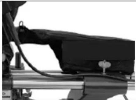
16.2.5 Emptying/changing the chip bag
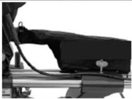
The machine is equipped with a chip bag for sawdust and chips.
Attention! The chip collection bag may only be used for cutting wood and wood-like materials!
Press the metal ring on the chip bag together and fasten it to the dust collector port. The chip bag can be emptied by means of a zipper on the underside.
16.2.6 Checking / changing carbon brusher

Check the carbon brushes after the first 50 hours of operation with a new machine or when new brushes are installed. After performing the first check, repeat the check every 10 operating hours.
If the carbon is worn to a length of 6 mm, or if the spring or contact wire is burnt or damaged, it is necessary to replace both brushes. If it proves that the brushes can be used after removal, it is possible to reassemble them.
When servicing the carbon brushes, open the two covers (13) counterclockwise. Then remove the carbon brushes. Replace the carbon brushes in reverse order.
16.2.7 Exchange table insert
CAUTION

If the table insert (19) is damaged, there is a risk that small parts may become stucked between the table insert and the saw blade and block the saw blade
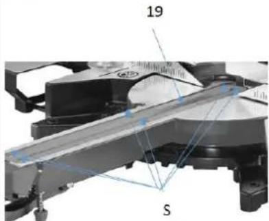
- Remove screws (S) from the table insert (19). If necessary, turn the rotary table and machine head to reach the screws.
- remove the table insert (19).
3 Install the new table insert (19).
4 Tighten the screws (S) on the table insert (19).
16.3 Storage
NOTE

Improper storage can damage and destroy important components. Only store packed or unpacked parts under the intended ambient conditions!
When not in use, store the machine in a dry, frost-proof and lockable place to prevent the formation of rust on the one hand and to ensure that unauthorised persons and in particular children have no access to the machine.
16.4 Disposal

Observe the national waste disposal regulations. Never dispose of the machine, machine components or operating materials (like oil,...) in residual waste. If necessary, contact your local authorities for information on the disposal options available.
If you buy a new machine or an equivalent device from your specialist dealer, he is obliged in certain countries to dispose of your old machine properly.
17 TROUBLESHOOTING
WARNING
Danger due to electrical voltage! Manipulating the machine with the power supply up can lead to serious injuries or death. Always disconnect the machine from the power supply before carrying out any troubleshooting work!
Many possible sources of error can be excluded in advance if the machine is properly connected to the mains.
If you are unable to carry out necessary repairs properly and/or do not have the required training, always consult a specialist to correct/solve the problem!
| Fault | Possible cause | Correction |
| Machine doesn’t start | No power supply | Connect to mains |
| Carbon brushes defect | Exchange carbon brushes | |
| Motor defect | Exchange motor | |
| ON-OFF-switch defect | Repair switch | |
| Workpiece kick-back | Dull saw blade | Replace saw blade |
| Wrong assembled saw blade | Check direction / assemble | |
| Wrong cutting angle | Angular position not correct | Adjusting the angular position |
| Saw blade cuts the table | Incorrect setting of cutting depth | Adjust cutting depth |
18 PRÓLOGO (ES)
¡Estimado cliente!:

Potpuno izvucite predmontiranu zaštitu od naginjanja (A) i osigurajte ju imbus vijkom (S).
Dubina reza može se kontinuirano postaviti pomoću vijka (22). U tu svrhu otpustite nazubljenu maticu (M) na vijku (22). Vijak (22) zavrnite ili odvrnite kako biste postavili željenu dubinu reza. Zatim opet zategnite nazubljenu maticu (M).
NAPOMENA

Provjerite postavku tako da izvršite probni rez.
- Nagib postavite u skladu sa željenim radnim postupkom i u skladu s tim namjestite graničnike.
- Označite crtu reza (laserom).
- Obradak postavite na graničnik i stol i fiksirajte ga držačem
- Glavu stroja stavite u gornji položaj.
-
Uključite stroj i pričekajte da se postigne puni broj okretaja lista pile (cca. 5 s),
-
Izvršite odrezivanje (glavu stroja pomaknite prema dolje) dok ne dođe u donji položaj.
- Glavu stroja stavite u gornji položaj
NAPOMENA

Glava stroja zategnuta je oprugom, glavu stroja nemojte samo pustiti, nego ju podižite za dršku sve dok ne dođe u gornji položaj (položaj za mirovanje.
- Pustite prekidač za uključivanje i isključivanje, pričekajte da se list kružne pile zaustavi.
■ Uklonite obradak
29.3.2 Potezni rezovi
Potezni rezovi prikladni su za dugačke rezove.
- Za piljenje vlačna naprava se otpuštanjem vijka za fiksiranje (23) deblokira tako da za vrijeme rezanja agregat pile ne može skliznuti unaprijed odn. unatrag.
Ako laser (17) više ne pokazuje točnu crtu reza, laser možete ponovno podesiti. Otpustite križne vijke (S) i podesite laser bočnim pomicanjem sve dok laserska zraka ne dođe na zupce lista pile. Opet čvrsto zategnite oba vijka (S).
30.2.5 Pražnjenje/zamjena vreće za piljevinu
Pila je opremljena vrećom za piljevinu (za piljevinu i ivere).
Pažnja! Vreća za piljevinu smije se upotrebljavati samo za piljenje drva i drvu sličnih materijala!
Stisnite metalni prsten na vreći za piljevinu i pričvrstite ga na izlazni otvor. Vreća za piljevinu može se isprazniti pomoću patentnog zatvarača na donjoj strani.
30.2.6 Kontrola / zamjena ugljenih četki
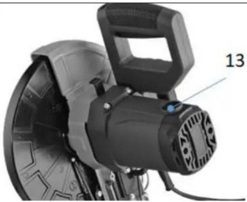
Provjerite ugljene četke nakon prvih 50 sati rada novim strojem ili kad su montirane nove četke. Nakon prve kontrole ponovite kontrolu svakih 10 sati rada.
(EN) With original ZIPPER spare parts you use parts that are attuned to each other shorten the installation time and elongate your machines lifespan.
IMP OR TAN T
The installation of other than original spare parts voids the warranty!
So you always have to use original spare parts
When you place a spare parts order please use the service formular you can find in the last chapter of this manual. Always take a note of the machine type, spare parts number and partname. We recommend to copy the spare parts diagram and mark the spare part you need.
You find the order address in the preface of this operation manual.
| No | Description | Qty | No | Description | Qty |
| 001 | Base | 1 | 089 | Rolling bearing 6001z3 | 1 |
| 002 | Rear support frame | 1 | 090 | Windshield | 1 |
| 003 | Cross pan head screw M6×10 | 2 | 091 | Rotor | 1 |
| 004 | Hexagon head bolt M8 × 20 | 1 | 092 | Needle roller bearing | 1 |
| 005 | Rubber foot | 4 | 093 | 608 bearing sleeve | 1 |
| 006 | Left movable support | 1 | 094 | Cross pan head tapping screw | 2 |
| 007 | Butterfly screw | 3 | 095 | Stator | 1 |
| 008 | Cross recess pan head screw | 3 | 096 | Housing shell | 1 |
| 009 | Butterfly screw | 2 | 097 | Cross pan head screw | 4 |
| 010 | Hexagon socket head cap screw | 4 | 098 | Brush handle | 2 |
| 011 | Movable support | 1 | 099 | Electric brush | 2 |
| 012 | Right movable support | 1 | 100 | Speed control module | 1 |
| 013 | Cross recess pan head screw | 4 | 101 | Housing rear cover | 1 |
| 014 | Linear bearing end cover | 2 | 102 | Cross pan head tapping screw | 8 |
| 015 | Linear bearing | 3 | 103 | Shaft bearing retainer 38 | 1 |
| 016 | Angle locking hand wheel | 1 | 104 | Cross pan head tapping screw | 2 |
| 017 | Type 2 non-metallic hexagon lock nut | 1 | 105 | Flat pad | 2 |
| 018 | Gasket | 2 | 106 | pulley | 2 |
| 019 | Connection base | 1 | 107 | Movable hood | 1 |
| 020 | Oblique pointer | 1 | 108 | Movable cover spring | 1 |
| 021 | Cross pan head screw | 9 | 109 | Cross pan head screw | 1 |
| 022 | Hexagon socket cap screws | 2 | 110 | Connecting rod head screw | 2 |
| 023 | Hexagon socket head cap screw | 1 | 111 | Three linkage assembly | 1 |
| 024 | Pull rod locking spring | 1 | 112 | Connecting rod central screw | 1 |
| 025 | Flat pad | 2 | 113 | Connecting rod washer | 1 |
| 026 | Nut M8 | 2 | 114 | Thread buckle | 1 |
| 027 | Hexagon socket head cap screw | 2 | 115 | Knob spring | 1 |
| 028 | Connecting base scale | 1 | 116 | Switch self-lock knob | 1 |
| 029 | Type 2 non-metallic hexagon lock nut | 1 | 117 | Self locking button sleeve | 2 |
| 030 | Flat gasket | 3 | 118 | Capacitance 0.22 μ f | 1 |
| 031 | Disc | 1 | 119 | Wiring row (3 rows) | 1 |
| 032 | Disc pointer | 1 | 120 | Lower handle | 1 |
| 033 | Clutch block | 1 | 121 | Crimping board | 1 |
| 034 | Fixed seat of disc locking rod | 2 | 122 | Circuit board | 1 |
| 035 | Cross pan head screw | 4 | 123 | Cable sheath | 1 |
| 036 | Pull rod locking spring | 2 | 124 | cable | 1 |
| 041 | Cross pan head screw | 2 | 125 | switch | 1 |
| 042 | Type 2 non-metallic hexagon lock nut | 2 | 126 | Switch trigger | 1 |
| 043 | Hexagon socket head cap screw | 2 | 127 | Cross pan head screw | 1 |
| 044 | Switch trigger spring | 3 | 128 | Cross countersunk head tapping screw | 1 |
| 045 | 9085 locking knob | 1 | 129 | switch | 1 |
| 046 | Fixed rod spring | 1 | 130 | Handle plastic cover | 1 |
| 048 | Slotting | 1 | 131 | Governor switch | 1 |
| 049 | Cross pan head screw | 1 | 132 | Cross pan head screw | 1 |
| 050 | Hexagon socket head cap screw | 1 | 133 | Upper handle | 1 |
| 051 | Hexagon socket head cap screw | 2 | 134 | Switch self-lock knob | 1 |
| 052 | Hexagon socket head cap screw | 1 | 135 | Handle plug | 1 |
| 053 | Cross pan head screw | 1 | 136 | Cross pan head screw | 3 |
| 054 | Pull rod | 2 | 180 | Cross pan head tapping screw | 2 |
| 055 | Self locking pin | 1 | 181 | Handle | 1 |
| 056 | Elastic pin | 1 | 182 | Disc locking rod | 1 |
| 057 | Ball nut | 1 | 183 | Locking block | 1 |
| 058 | Elastic pin | 2 | 184 | Side handle support block | 1 |
| 059 | Dust baffle | 1 | 185 | side handle | 1 |
| 060 | Support | 1 | 186 | Fixing rod | 1 |
| 061 | Large torsion spring | 1 | right / left table extension | ||
| 062 | Connecting shaft cover | 2 | 137 | Butterfly screw | 2 |
| 063 | Connecting shaft | 1 | 013 | Cross pan head screw | 2 |
| 064 | Pull rod rear cover | 1 | 138 | Extension rod | 4 |
| 065 | Pull rod gasket | 3 | 139 | Type 2 non-metallic hexagon lock nut | 2 |
| 066 | Saw blade set screw | 1 | 140 | Left wing | 1 |
| 067 | External pressure plate | 1 | 141 | Right wing | 1 |
| 068 | Blade | 1 | 142 | Left wing moveable slice | 1 |
| 069 | Internal pressure plate | 1 | 143 | Right wing moveable slice | 1 |
| 070 | Needle roller bearing | 1 | 144 | Cross pan head screw | 2 |
| 071 | Cross recessed countersunk head screw | 2 | 145 | Cross pan head screw | 4 |
| 072 | Bowl mat | 2 | LASER | ||
| 073 | Front cover | 1 | 137 | Laser back cover | 1 |
| 074 | Bearing press plate | 1 | 146 | Laser base | 1 |
| 075 | Output shaft | 1 | 147 | Cross pan head screw | 2 |
| 076 | Flat key | 1 | 148 | Cross countersunk head tapping screw | 2 |
| 077 | big gear wheel | 1 | 122 | PCB + laser | 1 |
| 078 | Limit post | 2 | 149 | Laser transparent cover | 1 |
| 079 | Bearing ring 15 for shaft | 1 | |||
| 080 | Needle roller bearing hk1010 | 1 | 154 | Fixed rod cover | 1 |
| 081 | Housing shell | 1 | 155 | Hand wheel | 1 |
| 082 | Knurled thin NUT | 1 | 156 | Fixed rod | 1 |
| 101 | Locking knob | 1 | 157 | Jaw iron | 1 |
| 084 | Shaft locking spring | 1 | 158 | Locking block | 1 |
| 085 | Shaft lock | 1 | 009 | Butterfly screw | 1 |
| 086 | Bumper block | 1 | 161 | Non standard screw | 1 |
| 087 | NUT M6 | 1 | 162 | Bag spring (+ 9105 bag) | 1 |
| 088 | Hexagon socket flat end set screw | 1 | 163 | Hex wrench | 1 |
Company ZIPPER Maschinen GmbH grants for mechanical and electrical components a warranty period of 2 years for amateur use; and warranty period of 1 year for professional use, starting with the purchase of the final consumer. In case of defects during this period, which are not excluded by paragraph 3, ZIPPER will repair or replace the machine at its own discretion.
2.) Report:
In order to check the legitimacy of warranty claims, the final consumer must contact his dealer. The dealer has to report in written form the occurred defect to ZIPPER. If the warranty claim is legitimate, ZIPPER will pick up the defective machine from the dealer. Returned shippings by dealers which have not been coordinated with ZIPPER, will not be accepted and refused.
3.) Regulations:
a) Warranty claims will only be accepted, when a copy of the original invoice or cash voucher from the trading partner of ZIPPER is enclosed to the machine. The warranty claim expires if the accessories belonging to the machine are missing.
b) The warranty does not include free checking, maintenance, inspection or service works on the machine. Defects due to incorrect usage of the final consumer or his dealer will not be accepted as warranty claims either. Some examples: usage of wrong fuel, frost damages in water tanks, leaving fuel in the tank during the winter, etc.
c) Defects on wear parts are excluded, e.g. carbon brushes, collection bags, knives, cylinders, cutting blades, clutches, sealings, wheels, saw blades, splitting crosses, riving knives, riving knife extensions, hydraulic oils, oil/air/fuel filters, chains, spark plugs, sliding blocks, etc.
d) Also excluded are damages on the machine caused by incorrect or inappropriate usage, if it was used for a purpose which the machine is not supposed to, ignoring the user manual, force majeure, repairs or technical manipulations by not authorized workshops or by the customer himself, usage of non-original ZIPPER spare parts or accessories.
e) After inspection by our qualified personnel, resulted costs (like freight charges) and expenses for not legitimated warranty claims will be charged to the final customer or dealer.
f) In case of defective machines outside the warranty period, we will only repair after advance payment or dealer's invoice according to the cost estimate (incl. freight costs) of ZIPPER.
g) Warranty claims can only be granted for customers of an authorized ZIPPER dealer who directly purchased the machine from ZIPPER. These claims are not transferable in case of multiple sales of the machine.
4.) Claims for compensation and other liabilities:
The liability of company ZIPPER is limited to the value of goods in all cases. Claims for compensation because of poor performance, lacks, damages or loss of earnings due to defects during the warranty period will not be accepted. ZIPPER insists on its right to subsequent improvement of the machine.
37 GARANTÍA (ES)
1.) Garantía:
We monitor the quality of our delivered products in the frame of a Quality Management policy.
Your opinion is essential for further product development and product choice. Please let us know about your:
- Impressions and suggestions for improvement.
- experiences that may be useful for other users and for product design
- Experiences with malfunctions that occur in specific operation modes
We would like to ask you to note down your experiences and observations and send them to us via FAX, E-Mail or by post
Erworben von / purchased from:
E-Mail/ e-mail:
Please describe amongst others in the problem: What has cause the problem/defect, what was the last activity before you noticed the problem/defect? For electrical problems: Have you had checked you electric supply and the machine already by a certified electrician?
3. Bitte beachten
/ Additional information
INCOMPLETELY FILLED SERVICE FORMS CANNOT BE PROCESSED! FOR GUARANTEE CLAIMS PLEASE ADD A COPY OF YOUR ORIGINAL SALES / DELIVERY RECEIPT OTHERWISE IT CANNOT BE ACCEPTED. FOR SPARE PART ORDERS PLEASE ADD TO THIS SERVICE FORM A COPY OF THE RESPECTIVE EXPLODED DRAWING WITH THE REQUIRED SPARE PARTS BEING MARKED CLEARLY AND UNMISTAKABLE. THIS HELPS US TO IDENTIFY THE REQUIRED SPARE PARTS FASTLY AND ACCEL- LERATES THE HANDLING OF YOUR INQUIRY.


- 1 INHALT / INDEX
- 1 INHALT / INDEX 2
- 2 SICHERHEITSZEICHEN / SAFETY SIGNS / SEÑALES DE SEGURIDAD / ZNAKOVI ZA SIGURNOST 6
- 13 TRANSPORT 30
- 14 ASSEMBLY 30
- 15 OPERATION 30
- 16 CLEANING, MAINTENANCE, STORAGE, DISPOSAL 34
- 17 TROUBLESHOOTING 38
- 18 PRÓLOGO (ES) 39
- 19 SEGURIDAD 40
- 3.3 TECHNISCHE DATEN / TECHNICAL DATA / DATOS TÉCNICOS / TEHNIČKI PODACI
- 4 VORWORT (DE)
- PLEASE READ AND OBEY THE SECURITY INSTRUCTIONS
- COPYRIGHT
- CUSTOMER SERVICE CONTACT
- 12.1 INTENDED USE OF THE MACHINE
- 12.1.1 TECHNICAL RESTRICTIONS
- 12.1.2 PROHIBITED USE / FORSEEABLE MISUSE
- 12.2 USER REQUIREMENTS
- 12.3 SAFETY DEVICES
- 12.4 GENERAL SAFETY INSTRUCTIONS
- 12.5 ELECTRICAL SAFETY
- 12.6 SPECIAL SAFETY INSTRUCTIONS FOR WOODWORKING MACHINES
- INSTRUCTIONS FOR THE USE OF THE LASER
- 12.7 HAZARD WARNINGS
- 13 TRANSPORT
- 14 ASSEMBLY
- 14.1 CHECKING SCOPE OF SUPPLY
- 14.2 THE WORKPLACE
- 14.3 ASSEMBLING THE MACHINE
- 15 OPERATION
- 15.1 INITIAL CHECK BEFORE START
- 15.2 OPERATION
- 15.2.1 LOCKING / UNLOCKING THE MACHINE HEAD IN THE TRANSPORT POSITION
- 15.2.2 SETTING THE ANGULAR POSITION OF THE WORKTABLE
- 15.2.3 SETTING THE ANGULAR POSITION OF THE MACHINE HEAD
- 15.2.4 SETTING THE STOPS/FENCES
- CAUTION
- 15.2.5 SETTING SAW BLADE SPEED
- 15.2.6 SETTING CUTTING DEPTH LIMITING
- NOTE
- 15.2.7 CONNECTION TO A DUST COLLECTION SYSTEM
- 15.2.8 SWITCH MACHINE ON-OFF
- 15.3 OPERATION MODES
- 15.3.1 MITRE CUTS
- 15.3.2 SLIDING CUTS
- 15.3.3 SLOT CUTS
- 16 CLEANING, MAINTENANCE, STORAGE, DISPOSAL
- WARNING
- 16.1 CLEANING
- 16.2 MAINTENANCE
- 16.2.1 MAINTENANCE SCHEDULE
- 16.2.2 ADJUSTING THE ANGULAR POSITION (BY MEANS OF STOP ANGLE)
- 90°-CUT
- 45°-CUT
- 16.2.3 SAW BLADE CHANGE
- 16.2.4 SETTING THE LASER
- 16.2.5 EMPTYING/CHANGING THE CHIP BAG
- 16.2.6 CHECKING / CHANGING CARBON BRUSHER
- 16.2.7 EXCHANGE TABLE INSERT
- 16.3 STORAGE
- 16.4 DISPOSAL
- 17 TROUBLESHOOTING
- 18 PRÓLOGO (ES)
- ¡ESTIMADO CLIENTE
- NAPOMENA
- 29.3.2 POTEZNI REZOVI
- 30.2.5 PRAŽNJENJE/ZAMJENA VREĆE ZA PILJEVINU
- 30.2.6 KONTROLA / ZAMJENA UGLJENIH ČETKI
- IMP OR TAN T
- THE INSTALLATION OF OTHER THAN ORIGINAL SPARE PARTS VOIDS THE WARRANTY
- 2.) REPORT
- 3.) REGULATIONS
- 4.) CLAIMS FOR COMPENSATION AND OTHER LIABILITIES
- 37 GARANTÍA (ES)
- 1.) GARANTÍA
- BITTE BEACHTEN
- ADDITIONAL INFORMATION
Brand : Zipper
Model : ZI-KGS255DS
Category : Saw