
THATEX - Fan Soler & Palau - Free user manual and instructions
Find the device manual for free THATEX Soler & Palau in PDF.
| Brand | Soler & Palau |
| Model | THATEX |
| Product type | Axial and centrifugal fan for explosive atmospheres (ATEX) |
| ATEX categories | 2G, 3G (gas); 2D, 3D (dust); 2GD, 3GD (combined) |
| Explosion groups (gas) | IIA, IIB, hydrogen (not IIC) |
| Temperature classes (gas) | T1 to T6 (max 450°C to 85°C) |
| Power supply (examples) | 230/400 V, 50 Hz (depending on motor) |
| Power (examples) | 1.1 kW / 4 kW (depending on model) |
| Ambient temperature | -20°C to +40°C |
| Maximum temperature of transported air | Up to 300°C (depending on version) |
| Tightening torques for screws | Table provided (e.g., M6: 3.9 Nm brass, 9.3 Nm steel 8.8) |
| Explosion protection | Protection type "h" for non-electrical equipment |
| Protection level | Gb (gas), Dc (dust) |
| Intended use | Ventilation of potentially explosive atmospheres (gas, vapors, mists, dusts) |
| Maintenance | Periodic inspection of clearances, bearings, cleanliness; cleaning without solvents |
| Safety | Mandatory grounding, contact protections, stop before intervention |
| Spare parts | Only original manufacturer parts |
| Repairs | Reserved for the manufacturer or a certified professional |
| Applicable standards | ATEX Directive 2014/34/EU, EN 14986, EN 60079-17, EN 60204-1 |
| Weight | Variable depending on model (not specified in the manual) |
Frequently Asked Questions - THATEX Soler & Palau
User questions about THATEX Soler & Palau
0 question about this device. Answer the ones you know or ask your own.
Ask a new question about this device
Download the instructions for your Fan in PDF format for free! Find your manual THATEX - Soler & Palau and take your electronic device back in hand. On this page are published all the documents necessary for the use of your device. THATEX by Soler & Palau.
USER MANUAL THATEX Soler & Palau
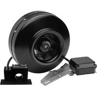
Axial and centrifugal fans
For use in potentially explosive atmospheres
OPERATING AND ASSEMBLY INSTRUCTIONS
Please read this manual carefully before starting the assembly and installation of this equipment.
GENERAL INFORMATION
This manual contains the necessary information for the transport, movement, handling, installation, use and maintenance of centrifugal and axial fans, both in terms of direct coupling and transmission.
These instructions are aimed at the people responsible for planning, putting into operation, using and maintaining the equipment, who must have the necessary qualifications and knowledge to carry out this task.
These instructions and the EC Declaration of Conformity for the supplied machine should be kept for future reference.
If the product is supplied with an instruction manual for the motor, it must be consulted for proper use and maintenance.
S&P Sistemas de Ventilación S.L.U. reserves the right to modify the construction and technical data in order to improve the equipment. The specifications, pictures, drawings and descriptions do not constitute any basis for claims.
S&P Sistemas de Ventilación S.L.U. is not responsible for any damages derived from failure to comply with the instructions contained in this manual.
S&P Sistemas de Ventilación S.L.U. is not responsible for damages derived from incorrect, inappropriate or unforeseen use, or as a consequence of non-authorized repairs or modifications.
SAFETY INSTRUCTIONS
SYMBOLS USED
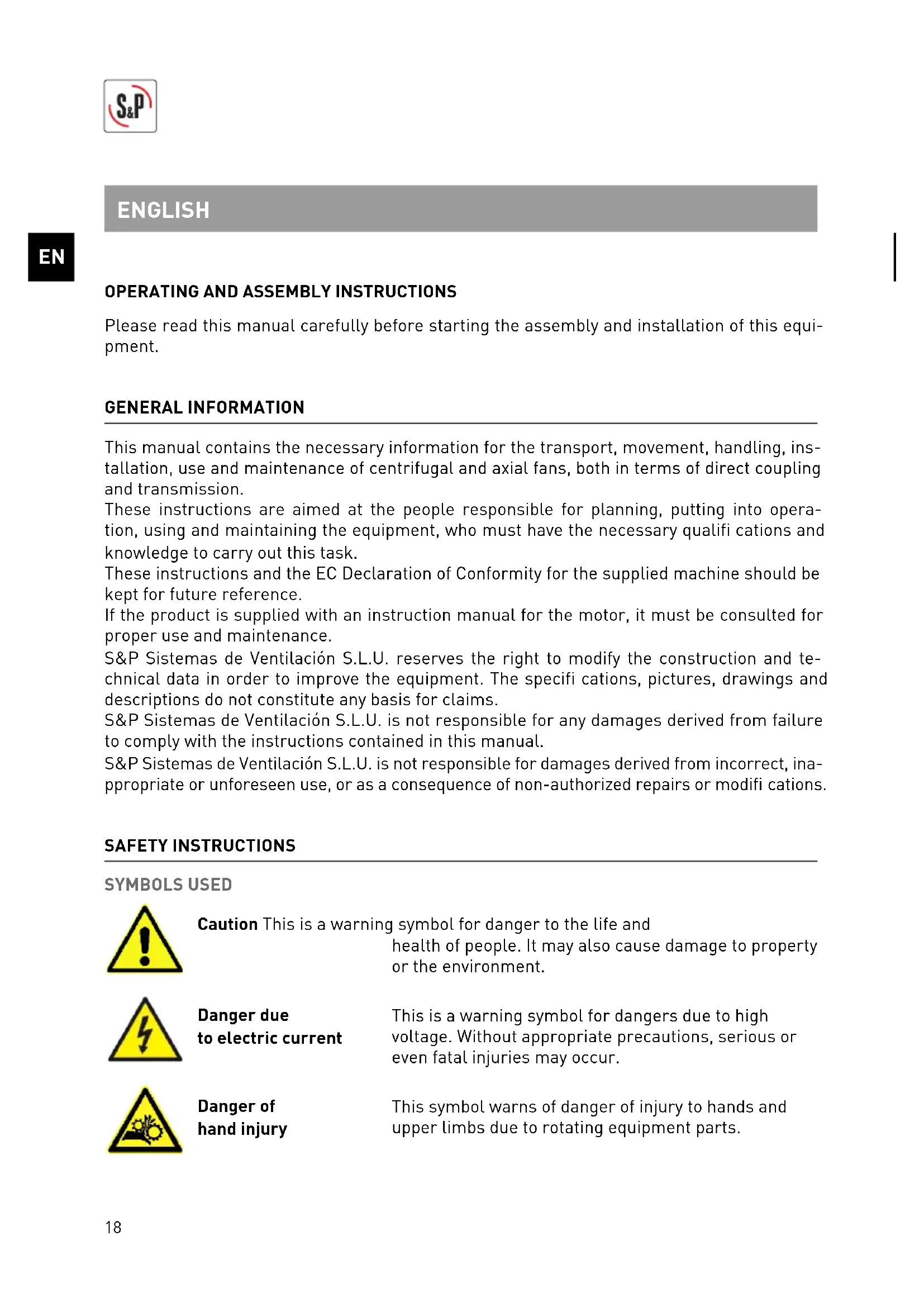
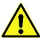
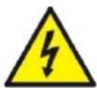
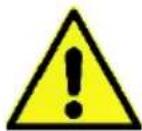
Caution This is a warning symbol for danger to the life and
health of people. It may also cause damage to property or the environment.
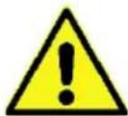
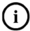
Danger due to electric current
This is a warning symbol for dangers due to high voltage. Without appropriate precautions, serious or even fatal injuries may occur.
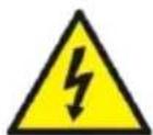
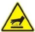
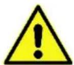
Danger of hand injury
This symbol warns of danger of injury to hands and upper limbs due to rotating equipment parts.
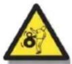
Danger of entrapment
This symbol warns of the danger of entrapment due to rotating equipment parts.
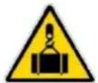
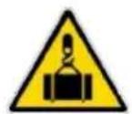
Danger when handling and moving the product
This symbol warns against hazards when the product is handled with cranes or hoists.
Danger of burns This symbol warns of the danger of burns when touching surfaces that may be at high temperatures.

Recycling symbol This symbol indicates information related to waste disposal.
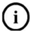
General information This symbol indicates information on using the equipment any other useful information.
TRANSPORT AND MOVEMENT

The following considerations must be taken into account for transport:
- Protect the fan from atmospheric agents
- Protect the fan from any blow that could damage it or jeopardize its physical integrity.
- During transport, avoid vibrations that might affect the bearings.
- When lifting or moving the fan, the intended attachment points or eye bolts must be used, where available.
- When moving the fan, use equipment that has adequate weight-handling capacity.
- Lifting the fan may cause it to oscillate, which can be dangerous. Never stand under the fan.
STORAGE
The following considerations should be taken into account for storage:
• We advise installing the fan immediately after receipt.
- If this is not possible, the fan should be stored in its original packaging in a closed, dry and weatherproof place. The fan must be protected against dirt, UV radiation and temperature changes.
- Check the condition of the fan on a monthly basis to avoid corrosion problems, especially in the possible contact areas between moving and fixed parts.
- Frequent checks are required on the bearings and ensuring they have enough grease. It is good practice to rotate the propeller or impeller to avoid damage to the bearings due to the weight of these components.
- It is advisable to seal the suction and discharge mouth of the fan in order to prevent the entry of foreign bodies.
- Avoid storage for long periods of time. We do not recommend storing the equipment for more than one year, and we advise consulting the manufacturer before starting up for periods longer than this.
SAFETY INSTRUCTIONS
This section contains instructions to prevent damage to persons and property. These instructions are not exhaustive and you should contact the manufacturer if you have any questions.
USE ACCORDING TO INTENDED PURPOSE
The company installing the fan must ensure that it is only used for its intended purpose and that it is in good condition and suitable for operation.
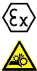
Only fans that are marked with the symbol may be used in areas classified as having a potentially explosive atmosphere. The intended use and limits of application are indicated on the product's name plate or in the accompanying instructions.
AREA OF APPLICATION
This fan complies with the construction requirements for categories 2 and 3 of equipment class II G (explosion group IIA, IIB and hydrogen) and categories 2 and 3 of group II D of Directive 2014/34/EU and is therefore not suitable for group I applications, or category 1 classifications of group II G or II D. The fan group is indicated on the fan's name plate.
This fan is intended for use in potentially explosive atmospheres containing gas, vapour, mist and/or dust. Such atmospheres may exist inside transported fluid, outside, or inside and outside the fan. Please keep in mind the maximum atmospheric conditions specified in EN 14986.
EXPLOSION PROTECTION CATEGORY
This fan can only be used in the areas suitable for its explosion protection category. This category is indicated on the name plate.
• Gas explosion group
Category 2G and 3G. Fans intended for use in the extraction of potentially explosive atmospheres in explosive groups IIA and IIB (EN60079-20) belong to this category. Under certain conditions these fans can also be used for the extraction of gases and vapours containing
hydrogen. As a result, the fans must not be used in other potentially explosive atmospheres in Group IIC.
• Dust explosion group
Category 2D and 3D. Fans intended for use in the extraction of potentially explosive atmospheres in the extraction of potentially explosive combinations of dust/air belong to this category.
• Combined gas/dust protection
Category 2GD and 3GD. Fans intended for use in the extraction of potentially explosive atmospheres in the extraction of potentially explosive combinations of gas and dust (*) belong to this category.
(*) Important: Make sure that explosive gas and dust atmospheres do not occur simultaneously.
TEMPERATURE CLASS
Fans for the above categories may not be used in fl ammable or explosive gas atmospheres with an ignition temperature lower than the maximum surface temperature of the fan.
The maximum surface temperature of Group II equipment corresponds, in the case of gases, to the Temperature Class indicated on the fan's name plate: T1,T2,T3,T4,T5,T6.
The maximum surface temperature in the case of air/dust mixtures is indicated on the fan name plate.
The relationship between temperature class and maximum surface temperature is specified in EN ISO 80079-36:
Table 1. Relationship between temperature class and maximum surface temperature
| Temperature class Maximum surface temperature (°C) | |
| T1 ≤ 450 | |
| T2 ≤ 300 | |
| T3 ≤ 200 | |
| T4 ≤ 135 | |
| T5 ≤ 100 | |
| T6 ≤ 85 | |
MARKING
There are many possible combinations in relation to the marking, so we cannot show all of them. Below is an explanation using several examples of a specific marking:
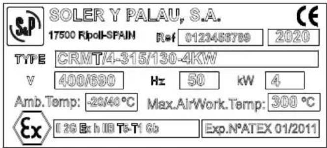
Example No. 1 for Gas (motor immersed in conveyed airflow)
EN

II 2G Ex h IIB T3 Gb
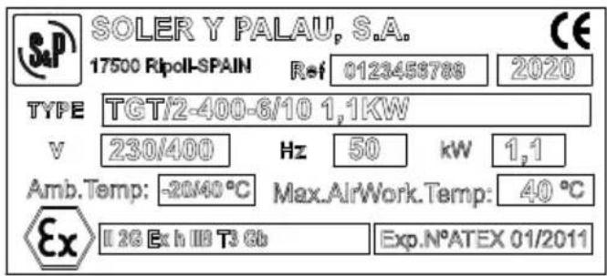

Complies with the ATEX Directive
II ATEX Group Equipment for surface facilities other than mines
2G Category 2. Equipment classified for installation in an explosive gas atmosphere - Zone 1
Ex Indicates that the device corresponds to one or more protection modes
h Explosion protection types for non-electrical devices
IIB Gas explosion group
T3 Motor surface temperature class
Gb Equipment Protection Level
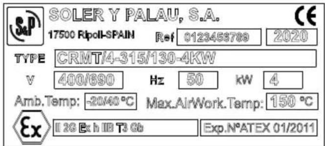
Example No. 2 for Gas (motor outside of conveyed airflow where the maximum surface temperature not only depends on the equipment itself, but also on the operating conditions)

II 2G Ex h IIB T5-T1 Gb

Complies with the ATEX Directive
II ATEX Group Equipment for surface facilities other than mines
2G Category 2. Equipment classified for installation in an explosive gas atmosphere - Zone 1
Ex Indicates that the device corresponds to one or more protection modes
h Explosion protection types for non-electrical devices
IIB Gas explosion group
Tx-T1 Surface temperature range as a function of operating conditions, where Tx is the motor temperature class (in the example it would be T5-T1) according to table 2 for GAS
Gb Equipment Protection Level
Example No. 3 for Gas (motor outside of conveyed airflow where the maximum surface temperature not only depends on the equipment itself, but also on the operating conditions)

II 2G Ex h IIB T3 Gb
EN

Complies with the ATEX Directive
II ATEX Group Equipment for surface facilities other than mines
2G Category 2. Equipment classified for installation in an explosive gas atmosphere - Zone 1
Ex Indicates that the device corresponds to one or more protection modes
h Explosion protection types for non-electrical devices
IIB Gas explosion group
T3 Surface temperature depending on operating conditions, according to Table 2 for Gas
Gb Equipment Protection Level
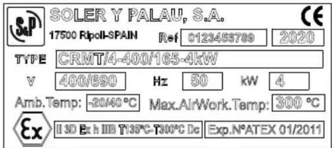
Example No. 4 for Dust (motor outside of conveyed airflow where the maximum surface temperature not only depends on the equipment itself, but also on the operating conditions)

II 3D Ex h IIIB T125°C Dc (for non-conductive dust)

II 3D Ex h IIIC T125°C Dc (for conductive dust)


Complies with the ATEX Directive
II ATEX Group Equipment for surface facilities other than mines
3D Category 3. Equipment classified for installation in an explosive dust atmosphere - Zone 22
Ex Indicates that the device corresponds to one or more protection modes
h Types of explosion protection for non-electrical equipment
IIIB o IIIC Dust explosion group
T125°C Surface temperature depending on operating conditions, according to Table 4 for Dust
Dc Equipment Protection Level
Example No. 5 for Dust (motor outside of conveyed airflow where the maximum surface temperature not only depends on the equipment itself, but also on the operating conditions)


II 3D Ex h IIIB T135°C-300°C Dc

Complies with the ATEX Directive
II ATEX Group Equipment for surface facilities other than mines
3D Category 3. Equipment classified for installation in an explosive dust atmosphere - Zone 22
Ex Indicates that the device corresponds to one or more protection modes
h Types of explosion protection for non-electrical equipment
IIIB o IIIC Dust explosion group
T135°C-Tx°C Surface temperature range as a function of operating conditions, where Tx is the motor temperature class (in the example it would be T135°C-T300°C) according to table 4 for Dust
Dc Equipment Protection Level
In the following tables you can see the temperature classes for the final equipment (gas) or the final temperature of the equipment (dust), according to the maximum temperature of the airflow conveyed by the equipment.
Table 2. Direct drive products for GAS
| DIRECT DRIVE PRODUCTS FOR GAS | ||||||
| Maximum conveyed airfl ow temperature supported by the equipment (°C) | Temperature class of the fi nal equipment depending on the temperature of the airfl ow and the temperature class of the motor | |||||
| Motor temperature class | ||||||
| T6 (85°C) | T5 (100°C) | T4 (135°C) | T3 (200°C) | T2 (300°C) | T1 (450°C) | |
| x ≤80 T6 T5 T4 T3 T2 T1 | ||||||
| 80< x ≤95 T6-T5 T5 T4 T3 T2 T1 | ||||||
| 95< x ≤130 T6-T4 T5-T4 | T4 T3 T2 T1 | |||||
| 130< x ≤195 | T6-T3 | T5-T3 | T4-T3 | T3 | T2 | T1 |
| 195< x ≤290 | T6-T2 | T5-T2 | T4-T2 | T3-T2 | T2 | T1 |
| 290< x ≤440 | T6-T1 | T5-T1 | T4-T1 | T3-T1 | T2-T1 | T1 |
Table 3. Transmission coupling products for GAS
| TRANSMISSION COUPLING PRODUCTS FOR GAS | |||||
| Maximum conveyed airfl ow temperature supported by the equipment (°C) | Temperature class of the fi nal equipment depending on the temperature of the airfl ow and the temperature class of the motor | ||||
| Motor temperature class | |||||
| T6 (85°C) | T5 (100°C) | T4 (135°C) | T3 (200°C) | T2 (300°C) T1 (450°C) | |
| x ≤80 T4 T4 T4 T3 T2 T1 | |||||
| 80< x ≤95 T4 T4 T4 T3 T2 T1 | |||||
| 95< x ≤130 T4 T4 T4 T3 T2 T1 | |||||
| 130< x ≤195 T4-T3 T4-T3 T3 T2 T1 | |||||
| 195< x ≤290 T4-T2 T4-T2 T4-T2 T3-T2 T2 T1 | |||||
| 290< x ≤440 T4-T1 T4-T1 T4-T1 T3-T1 T2-T1 T1 | |||||
Table 4. Direct coupling products for DUST
| DIRECT COUPLING PRODUCTS FOR DUST | ||
| Maximum conveyed airfl ow temperature supported by the equipment (°C) | Temperature of the fi nal equipment depending on the temperature of the airfl ow conveyed and maximum temperature of the motor | |
| Motor temperature class | ||
| T125 T135 | ||
| x ≤125 | T125°C | T135°C |
| 125<T125°C - Tx°CT135°C | T125°C - Tx°C | T135°C |
| 135<T125°C - Tx°CT135°C - Tx°C | T125°C - Tx°C | T135°C - Tx°C |
Table 5. Transmission coupling products for DUST
| TRANSMISSION COUPLING PRODUCTS FOR DUST | ||
| Maximum conveyed airfl ow temperature supported by the equipment (°C) | Temperature of the fi nal equipment depending on the temperature of the airfl ow conveyed and maximum temperature of the motor | |
| Motor temperature class | ||
| T125 T135 | ||
| x ≤125 | T135°C | T135°C |
| 125<T135°CT135°C | T135°C | T135°C |
| 135<T135°C - Tx°CT135°C - Tx°C | T135°C - Tx°C | T135°C - Tx°C |
The marking on the fan plate must be compared with the data for intended use, to ensure correct application. Any use other than the approved use according to the marking on the name plate is unsuitable. The manufacturer does not accept any liability for damage caused by improper use.
Reading and following these operating instructions is also part of the intended use of the equipment. The information and safety instructions for the components of this product, such as motors, capacitors, etc., must also be followed.
The fan has been subjected to a risk analysis in accordance with the provisions of Machinery Directive 2006/42/EC. It is the user's responsibility to carry out a risk analysis at his or her own risk, taking into account how the fan will be used. The risks to be considered are those listed below:
- Improper installation. Fans installed in an improper manner constitute a risk to people and things. Fans must be installed by qualified and experienced personnel. Fan installation must comply with all the safety regulations and laws in force in the country where it is installed. For installation without inlet and outlet ducts, protections that meet the requirements indicated in ISO 13857 must be installed.
- Rotation speed. The fan has been designed to operate safely below a maximum rotation speed limit (consult the manufacturer). Never exceed this speed limit, as doing so poses a high safety risk.
- Transmission ratio. For transmission fans, the appropriate transmission ratio must be used for the motor power and operating speed, without ever exceeding the maximum rotation speed, and the pulleys and belts must be sized according to the manufacturer's instructions.
- Working temperature. The fan has been designed to work within a temperature range that must not be exceeded.
- Protective devices. Do not remove the protective devices already mounted on the fan, as doing so will pose a serious risk to safety.
- Electrical risks. Maintenance of electrical parts must be carried out by qualified personnel, after having consulted and read this manual and any manuals corresponding to associated electrical devices (motor, capacitor, etc.).
- Entry of foreign bodies. If there is a risk of foreign bodies entering the fan, appropriately designed protective guards must be installed to prevent them from entering the fan's interior. Check these guards periodically and remove any foreign bodies where necessary.
- Dangerous gases. If the fluid conveyed by the fan presents a danger to health (toxic or noxious gases), the fan should be designed in such a way that it avoids the emissions of such gases. If this is not possible, suitable equipment must be provided for the type of fluid conveyed.
- Inspection doors. If the fan is equipped with an inspection door, this cannot be opened while the fan is in motion.
- Mounting the fan. Mounting the fan using other parts than those assigned by the manufacturer may present a risk to the safety and correct operation of the fan.
- Mobile use. Improper use includes installing the fan in vehicles, boats, aircraft or installation that sets the fan in motion, unless this has been explicitly agreed and the fan has been designed specifically for this type of application.
- Vibration. The operating conditions must be such that the vibration level of the fan is within the limits established in the ISO 14694 standard for industrial fans, unless different limits have been agreed.
- Inadequate maintenance. Maintenance must be carried out by qualified and experienced personnel and must be in accordance with the manufacturer's instructions given in this manual.
- Fans of the TD and TH ranges must not be installed or used in unclean or unsupervised environments.
SPECIFIC RISKS IN EXPLOSIVE ATMOSPHERES. IMPROPER USE
During use of a fan in an explosive atmosphere and/or with explosive gases, the following potentially dangerous ignition sources must be taken into account:
- Improper use. The fan must not be used outside the ATEX application limits indicated on the name plate.
• Environmental considerations: The following parameters must be observed:
a) Ambient temperature
b) Ambient humidity
c) Environmental corrosiveness
d) Environmental pollution
- Formation of sparks through friction or impact between rotating parts (propeller, impeller, etc.) and fixed parts (casing, mouth, volute, etc.).
- Formation of sparks through friction or impact of foreign bodies or residue sucked into the fan.
- Formation of sparks due to the discharge of electrostatically charged components.
- Formation of sparks due to dust deposits forming clouds or thick layers.
- Hot surfaces due to excess strain or heat produced by friction between rotating and stationary parts.
- Excessive vibration (e.g. due to unbalance) which can cause some components to overheat or cause rotating and stationary parts to come into contact with each other.
- Zone transfer. Depending on their use, some fans may leak between the internal and external parts, or vice versa, and this must be taken into account. These leaks occur mainly in the area of the shaft passage, at the junction between the different parts of the fan casing and between the fan and the installation.
- Lightning. If lightning strikes in an explosive atmosphere, ignition will always occur. There is also the possibility of ignition due to the high temperatures, which may occur in the metal parts conducting the shock. For this reason, installations must be equipped with surge protection systems in suitable locations.
- Electromagnetic and radio frequency waves. All systems that produce and use high-frequency electrical energy, laser radiation or solar radiation may cause the ignition of an explosive atmosphere. Appropriate measures must be taken to prevent this.
- Ionizing radiation. Ionizing radiation that is produced, for example, by X-ray tubes and
radioactive substances, can cause the ignition of explosive atmospheres. If the fan is installed near such a source of radiation, appropriate measures must be taken to prevent this.
- Ultrasound. A large proportion of the energy released by an electro-acoustic emitter can be absorbed by solid or liquid substances, resulting in an increase in temperature that can produce ignition in an explosive atmosphere.
- Adiabatic compression and shock waves. In the case of adiabatic compression or shock waves, high temperatures can be reached, which can cause the explosive atmosphere to ignite, and measures must therefore be taken to prevent this from occurring.
- Exothermic reactions. This may act as a source of ignition when the heat release rate is higher than the heat release rate to the exterior, which means that substances with a tendency to ignite should be avoided. The user must check that the gases and dust in the fan do not consist of mixtures liable to produce exothermic reactions at temperatures higher than the temperature or temperature class indicated on the fan's name plate.
PRODUCT SAFETY
This fan complies with technological guidelines at the time of delivery and is safe to operate. The fan and its accessories must only be installed and put into operation only if they are in perfect condition and in accordance with the instructions in the operating manual as well as the safety regulations in the country of installation.
INSTALLATION AND COMMISSIONING
Please follow the steps below before start-up:
- Check the condition of the equipment.
- Equipment that has been damaged during commissioning must not be put into operation.
- If the fan is accessible to users after installation and may pose a risk to health and safety, then in order to comply with Machinery Directive 2006/42/EC, suitable protection must be fitted to both the suction and discharge. The safety distances must comply with EN ISO 13857 guidelines. These protections can be determined in the accessories section of the S&P catalogue.
- When installing any type of protection on the fan's suction or discharge, please ensure that the requirements regarding the clearance between rotating and stationary parts are met, in accordance with EN 14986 guidelines.
- The equipment has been designed and manufactured in such a way that the clearances between rotating and stationary parts are as indicated in EN 14986 guidelines. However, during transport and handling of the equipment, deformations may occur in the fan that may affect these clearances. For this reason, you must check the most important clearances before start-up.
- Pay special attention to the clearance between rotating and stationary parts. The clearance must be at least 0.5% of the contact diameter (diameter of the rotating part at the section where it may touch the stationary part) but must be no less than 2 mm on the radial or axial planes, and need not be greater than 13 mm. This also applies to non-contact shaft seals.
- Contact shaft seals are not subject to these precautions and must be manufactured from suitable materials and designed with an assessment of the ignition risk.
- The fan must be installed in such a way that it is protected against external forces and vibrations and, if necessary, it must be installed on an anti-vibration support.
- If fl exible connections are required to isolate the fan from the installation ducts, they must be made of a material that complies with EN 14986 guidelines to avoid possible static electricity shocks.
- Make sure that possible sources of ignition cannot spread through the suction or discharge outlets or directly into hazardous areas.
- Check that all parts rotate freely without friction and without any obstacles.
- Check that foreign objects or residue cannot be sucked in and that no foreign bodies or residues can be released inside the fan.
- Check that the model and characteristics of the fan (voltage, frequency, speed, ATEX marking, etc.) are correct. (maximum variation of voltage and frequency: 5%).
- Check that the grounding has been carried out correctly in accordance with EN 60204-1 guidelines and using the specific terminals provided by the manufacturer.
- Check that the safe distances between the live parts are adequate in accordance with EN 60204-1.
- If the motor is supplied by a frequency converter, the following considerations must be taken into account:
- The specific data on the motor's name plate must be consulted.
- The motor must be equipped with a thermal protection device connected to a control system that cuts off the power supply to the motor in the event of overheating.
- The set speed and/or frequency limit on the fan name plate must not be exceeded.
- Check that the current absorbed during operation does not exceed the values specified on the fan or motor name plate.
• After two hours of operation, check that the screws are still correctly fastened and tightened to the correct torque and retighten them if necessary.

| Tightening torque settings (Nm) | ||||
| Metric Brass Stainless steel | a2-70 | Stainless steel a2-80 | Steel 8.8 | |
| M2 0,14 --- --- 0,33 | ||||
| M2,5 0,29 --- --- 0,7 | ||||
| M3 0,5 0,9 1,2 1,2 | ||||
| M4 1,2 2,1 2,7 2,7 | ||||
| M5 2,2 4,1 5,4 5,4 | ||||
| M6 3,9 7,1 9,3 9,3 | ||||
| M8 9 17,5 22 22 | ||||
| M10 17 34 44 45 | ||||
| M12 59 76 77 | ||||
| M14 91 121 125 | ||||
| M16 140 187 190 | ||||
| M18 | --- --- | 270 | ||
| M20 273 364 380 | ||||
| M22 | --- --- | 515 | ||
| M24 472 659 655 | ||||
| M27 682 909 1000 | ||||
| M30 930 | 1240 | 1350 | ||
- Depending on the temperature of the fluid transported and the operating conditions, the surface temperatures of the accessible parts may be high and appropriate precautions must be taken.
- When commissioning or operating the fan, there is a danger of suction. Therefore, no loose clothing should be worn, nor should necklaces, jewellery, etc., be used that poses a risk of being sucked into the equipment. We recommend tying back or covering long hair.
- Please note that the supplied fan is not completely watertight. Therefore, when the fan has an open inlet and/or outlet (installation mode A, B, C according to EN ISO 13349) the inside and outside of the fan must be in the same category. In the case of installation mode type D (tubular inlet and outlet), there cannot be more than one category of difference between the inside and outside (where the motor is). For example, the conveyed air can be considered as zone 1 and the outside air has to be at least zone 2 (unclassified zones are not allowed).
- The ILT ATEX fan range can only be used with the power supply and protection devices chosen by the manufacturer in the specific instruction manual for the equipment.
Additional note for products supplied without a motor or transmission
- The installer must ensure that the complete assembly of the fan with the drive and motor complies with the ATEX directive and the requirements of EN 14986.

When carrying out maintenance, the instructions provided by the manufacturer must be observed:
- All work must be carried out by qualified personnel in strict accordance with EN 60079-17 standards or the national standards in the country where the product is installed.
- All maintenance operations must be carried out with the fan turned off and all power supplies disconnected, whether electrical, neutral or otherwise.
- It is strictly forbidden to carry out any work on components of the equipment that are live.
- If the equipment is powered by a frequency converter, it must be taken into account that high currents may leak in the protective ducts. Therefore, dangerous voltages in the fan casing should be avoided, and a grounding connection must be provided in accordance with EN 50178 standards.
- Following a mains supply power failure, the fan may start again automatically after the power supply is restored.
- Please note that the rotating part of the fan may continue to rotate through inertia for some time even after it has been disconnected from the power supply.

- Do not wear any loose clothing, necklaces or jewellery that could be sucked in or caught in the fan. We also recommend you tie back or cover your hair.
- The frequency of maintenance must take into account the specific operating conditions of the equipment. Unexpected noise, high temperatures and vibrations must be taken into account. In particular, if noticeable problems are detected, the fan must be taken out of service and inspected.
- In the case of transmission fans, particular attention must be paid to the correct alignment and tension of transmission belts to avoid slippage or excessive force on the bearings and moving parts.
- The propeller or impeller must be checked periodically to detect any damage that might cause an imbalance in the moving parts.
- If monitoring systems have been installed (such as temperature, ventilation, etc.) they should be checked regularly.
- Cleaning operations should be carried out at appropriate intervals on any areas where dust can be expected to form on the surface layers of the fan itself and its components.
- Accumulated dirt on the rotating parts may lead to imbalances that could end up causing damage and safety problems.
- Products containing solvents, components that can cause electrostatic shocks, and components that may pose a safety hazard, must not be used for cleaning.
- Make sure to clean in such a way that it does not affect the degree of balance of the moving parts or cause damage to the equipment.
- A visual inspection must be carried out to check for any damage, friction between moving and fixed parts, cracks, break points, deformations, and so on.
- Pay special attention to the clearance between rotating and stationary parts. The clearance must be at least 0.5% of the contact diameter (diameter of the rotating part at the section where it may touch the stationary part) but must be no less than 2 mm on the radial or axial planes, and need not be greater than 13 mm.
- Contact shaft seals are not subject to these precautions and must be manufactured from suitable materials and designed with an assessment of the ignition risk.
- Fans in the TD and TH ranges are only intended for clean environments where the cleanliness of the inside of the fan and its ducts has to be monitored regularly.
REPAIRS AND MODIFICATIONS
Repairs must be carried out in accordance with the criteria stipulated in EN 60079-19 guidelines.
For safety reasons, repairs should only be carried out by the manufacturer. The user may not carry out repairs, interventions or modifications to the equipment on his own unless authorized in writing by the manufacturer. Otherwise the manufacturer accepts no liability.
If the repairs are not carried out by the manufacturer, they must be carried out in a workshop that has the necessary technological means and skills and that is properly qualified.
Only original spare parts should be used. The safety of the equipment is guaranteed by its components, which have been specifically designed to remove or minimize causes of ignition in an explosive atmosphere.
The spare parts lists for standard (non-ATEX) equipment are not valid for ATEX equipment and therefore cannot be used.
Any components not supplied by the manufacturer are not authorized to be used in the equipment by the manufacturer.
DECOMMISSIONING AND RECYCLING
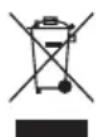
EEC regulations and the commitment we have with future generations compel us to recycle materials; we ask you don't forget to dispose of all the remaining elements of the packaging in the proper recycling containers. If your apparatus is also labelled with this symbol, please do not forget to take the old apparatus to the nearest waste disposal facility.
FRANÇAIS
INSTRUCTIONS DE FONCTIONNEMENT ET DE MONTAGE
INDICATIONS DE SÉCURITÉ
SYMBOLES UTILISÉS
Complies with the following standards and Directives:
- Directive 2014/34/UE - Directive 2014/30/UE - Directive RoHS 2011/65/EU - EN 60079-7
- Directive 2009/125/CE - Directive 2006/42/CE - EN 14986 - EN 60079-0
- EN 60204-1:2006 // EN 62311:2008 // EN ISO 12100:2010 // EN ISO 12499:2008 // EN ISO 13857:2008
Directiva 2006/42/EC, Anexo II 1-B
Directive 2006/42/EC, Anexo II 1-B
Directive 2006/42/EC, Annex II 1-B
Should the product defined above, be used as part of machine, then it must not be put into service until the machine in which it is incorporated has been declared in conformity with the provisions of the Machinery Directive 2006/42/CE.
The technical Director is the person authorized to compile relevant technical documentation in accordance with Annex VII (B). Compliance with EN ISO 13857 refers to safety devices when supplied, and installed, with the product. The responsibility for compliance with EN ISO 13857 is the installer of the system the product is applied.
We are committed to provide relevant information on this product in response to reasonable request by national authorities.


- Axial and centrifugal fans
- OPERATING AND ASSEMBLY INSTRUCTIONS
- GENERAL INFORMATION
- SAFETY INSTRUCTIONS
- SYMBOLS USED
- TRANSPORT AND MOVEMENT
- STORAGE
- USE ACCORDING TO INTENDED PURPOSE
- AREA OF APPLICATION
- EXPLOSION PROTECTION CATEGORY
- • Gas explosion group
- • Dust explosion group
- • Combined gas/dust protection
- TEMPERATURE CLASS
- MARKING
- II 2G Ex h IIB T3 Gb
- II 2G Ex h IIB T5-T1 Gb
- II 3D Ex h IIIB T125°C Dc (for non-conductive dust)
- II 3D Ex h IIIB T135°C-300°C Dc
- SPECIFIC RISKS IN EXPLOSIVE ATMOSPHERES. IMPROPER USE
- PRODUCT SAFETY
- INSTALLATION AND COMMISSIONING
- Additional note for products supplied without a motor or transmission
- REPAIRS AND MODIFICATIONS
- DECOMMISSIONING AND RECYCLING
- FRANÇAIS
- INSTRUCTIONS DE FONCTIONNEMENT ET DE MONTAGE
- INDICATIONS DE SÉCURITÉ
- SYMBOLES UTILISÉS
- Directiva 2006/42/EC, Anexo II 1-B
- Directive 2006/42/EC, Anexo II 1-B
- Directive 2006/42/EC, Annex II 1-B
Brand : Soler & Palau
Model : THATEX
Category : Fan