
TDECOWATT - Fan Soler & Palau - Free user manual and instructions
Find the device manual for free TDECOWATT Soler & Palau in PDF.
| Product type | Ventilation fan |
| Brand | Soler & Palau |
| Model | TDECOWATT |
| Power supply | 220-240 V ~ 50/60 Hz |
| Maximum power | 50 W |
| Fan diameter | 30 cm (estimated) |
| Approximate weight | 3 kg |
| Materials | Metal and plastic |
| Main functions | Air extraction or blowing |
| Noise level | Variable depending on speed (not specified) |
| Protection rating | IP X4 (estimated) |
| Maintenance | Regular cleaning of blades and grilles |
| Safety | Mandatory grounding, integrated thermal protection |
| Installation | Must be carried out by a qualified professional |
| Spare parts | Available through the Soler & Palau after-sales service network |
| Repairability | Repairable by an approved professional |
| Max ambient temperature | 40 °C (estimated) |
| Use | Indoor only |
Frequently Asked Questions - TDECOWATT Soler & Palau
User questions about TDECOWATT Soler & Palau
0 question about this device. Answer the ones you know or ask your own.
Ask a new question about this device
Download the instructions for your Fan in PDF format for free! Find your manual TDECOWATT - Soler & Palau and take your electronic device back in hand. On this page are published all the documents necessary for the use of your device. TDECOWATT by Soler & Palau.
USER MANUAL TDECOWATT Soler & Palau
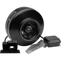
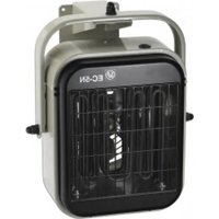
natural_image
Exterior view of multiple white industrial pipe fittings with no visible text or symbols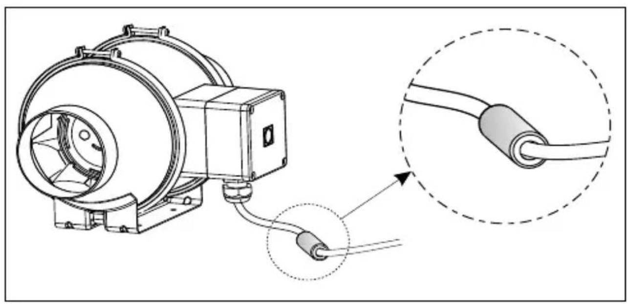
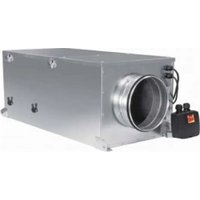
natural_image
Technical line drawing of a mechanical device with wiring and a close-up inset showing a cable (no text or symbols present)
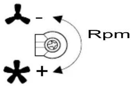
TD-160/100
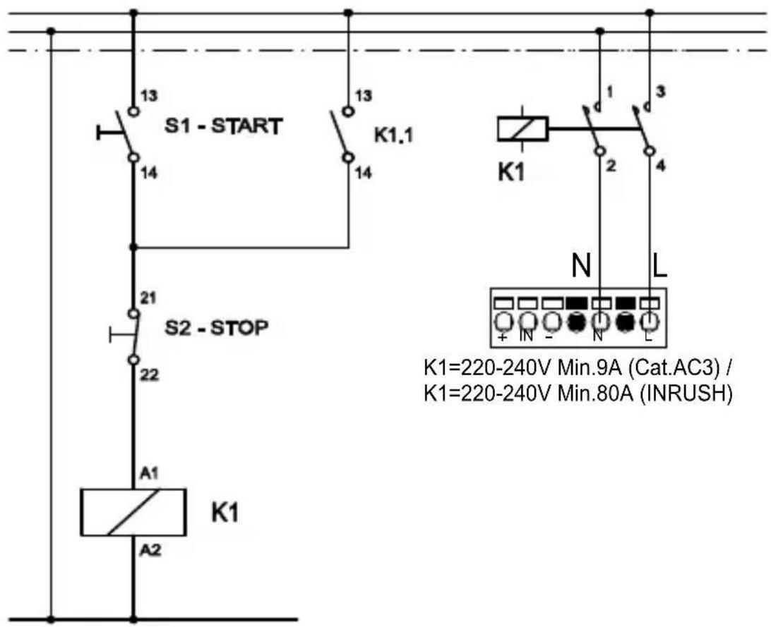
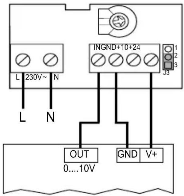
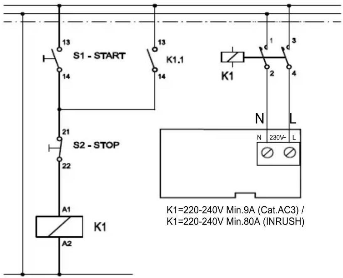
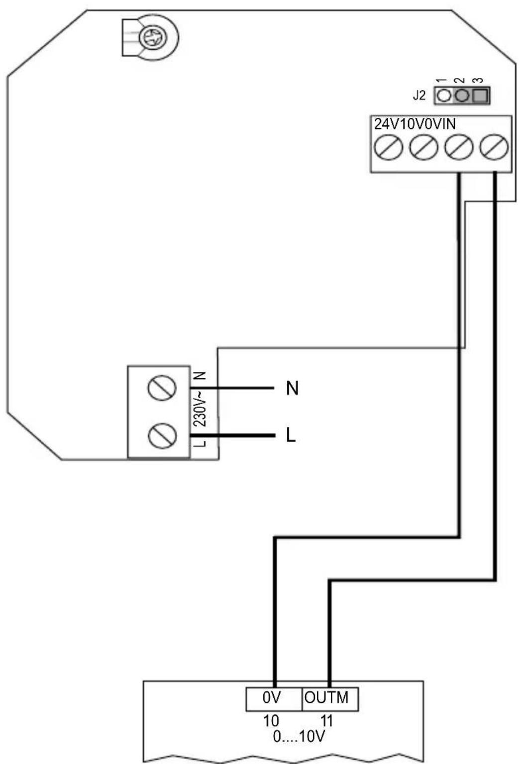
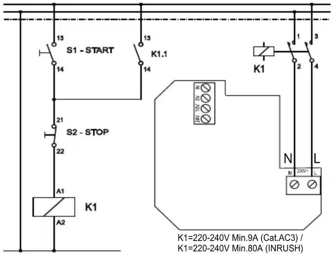
DIAGRAMA PARA CICLOS DE PARO/MARCHA CON EL CONTROL - RECOMENDADO DIAGRAM FOR ON/OFF CYCLES VIA CONTROL - RECOMMENDED DIAGRAMME POUR CYCLES MARCHE/ARRET AVEC LE CONTROLE - RECOMMANDE
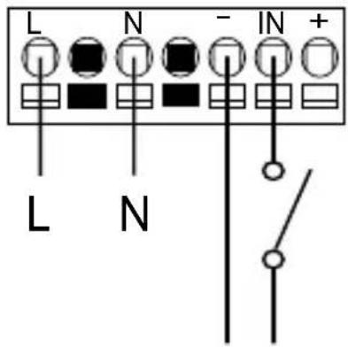
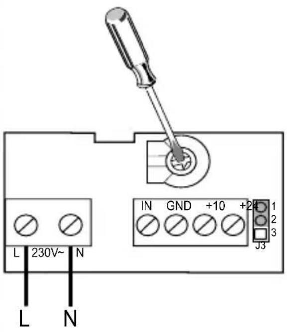
DIAGRAMA PARA CICLOS DE PARO/MARCHA A TRAVES DEL SUMINISTRO DIAGRAM FOR ON/OFF CYCLES VIA SUPPLY DIAGRAMME POUR CYCLES MARCHE/ARRET PAR L'ALIMENTATION
TD-250/100, 350/125
REB-ECOWATT
TD-250/100,350/125
CONTROL-ECOWATTAC/DC
EXTERNAL-SENSOR
TD-250/100, 350/125
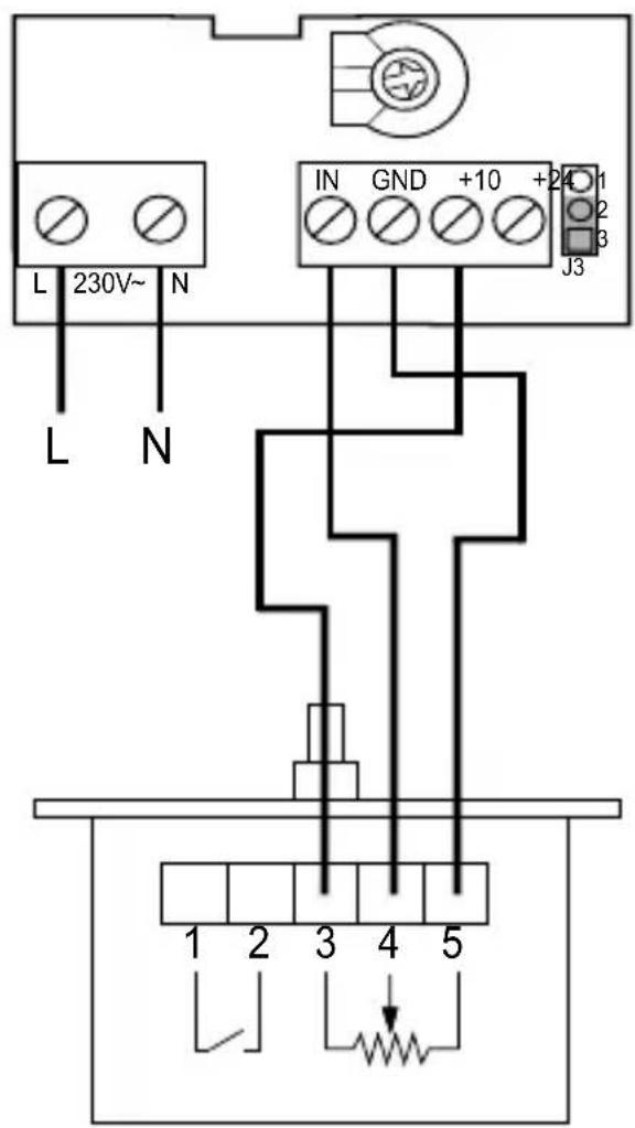
DIAGRAMA PARA CICLOS DE PARO/MARCHA CON EL CONTROL - RECOMENDADO DIAGRAM FOR ON/OFF CYCLES VIA CONTROL - RECOMMENDED DIAGRAMME POUR CYCLES MARCHE/ARRET AVEC LE CONTROLE - RECOMMANDE

DIAGRAMA PARA CICLOS DE PARO/MARCHA A TRAVES DEL SUMINISTRO DIAGRAM FOR ON/OFF CYCLES VIA SUPPLY DIAGRAMME POUR CYCLES MARCHE/ARRET PAR L'ALIMENTATION
TD-500/150, TD-500/160, TD-800/200
TD-500/150, TD-500/160, TD-800/200

TD-500/150, TD-500/160, TD-800/200
CONTROL-ECOWATTAC/DC
TD-500/150, TD-500/160, TD-800/200
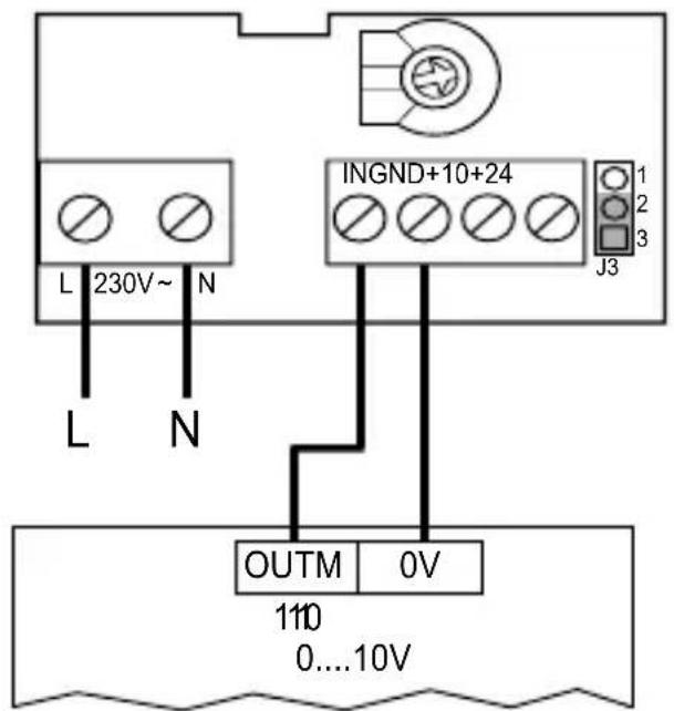
DIAGRAMA PARA CICLOS DE PARO/MARCHA CON EL CONTROL - RECOMENDADO DIAGRAM FOR ON/OFF CYCLES VIA CONTROL - RECOMMENDED DIAGRAMME POUR CYCLES MARCHE/ARRET AVEC LE CONTROLE - RECOMMANDE
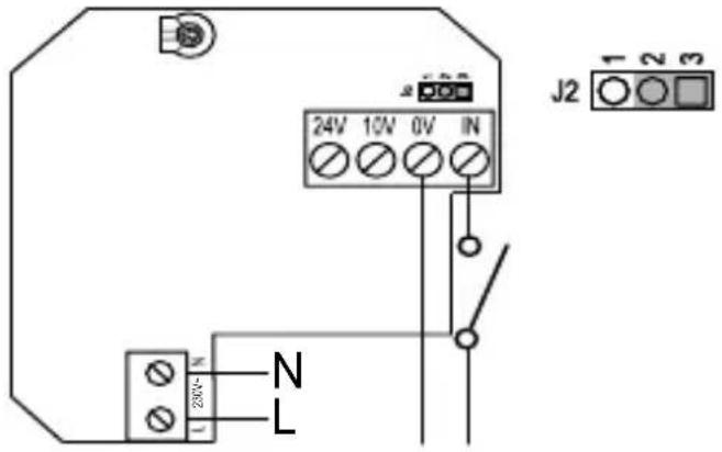
DIAGRAMA PARA CICLOS DE PARO/MARCHA A TRAVES DEL SUMINISTRO DIAGRAM FOR ON/OFF CYCLES VIA SUPPLY DIAGRAMME POUR CYCLES MARCHE/ARRET PAR L'ALIMENTATION
ESPAÑOL
Thank you for placing your confidence in S&P by buying this product. It has been manufactured following current technical safety regulations and in compliance with EC standard. Please read this instructions booklet carefully before installing or starting up the product. It contains important information on personal and user safety measures to be followed while installing, using and carrying out maintenance work on the equipment. Once the product has been installed, please hand in this booklet to the end user. Check that the apparatus is in perfect condition while unpacking. Any fault or damage caused in origin is covered by the S&P guarantee. Please make sure that the apparatus coincides with the product you have ordered and that the details on the instructions plate fulfil your necessities.
TRANSPORT AND MANIPULATION
- The packaging used for this apparatus has been designed to support normal transporting conditions. The apparatus must always be transported in its original packaging as not doing so could deform or damage the product.
- The product should be stored in a dry place in its original packaging, protected from dust and dirt until it is installed in its final location. Do not accept delivery if the apparatus is not in its original packaging or
shows clear signs of having been manipulated in any way.
- Do not place heavy weights on the packed product and avoid knocking or dropping it.
IMPORTANT INFORMATION FOR THE SAFETY OF INSTALLERS AND USERS
• Installation must only be carried out by qualified persons.
- Make sure that the installation complies with each country's current mechanical and electrical norms.
- Once ready to use, the apparatus must fulfil the following standards:
- Standard for Low stalled, make sure Pressure Instal- that the building has ments 2006/95/CE. suffi cient air intakes - Standard for Elec- to assure adequate tromagnetic Com- combustion.
patibility 2004/108/CE.
- Ventilators, or apparatus that include them, have been designed to move the air in the area stipulated on their characteristics plate.
- This apparatus must not be used in explosive or corrosive atmospheres.
- If a ventilator is going to be installed to extract air from premises where a boiler or other combustion apparatus are in-
- The extractor outlet must not be connected to a duct used to exhaust smoke or fumes from any appliance that uses gas or any other type of fuel.
- This appliance can be used by children aged from 8 years and above and persons with reduced physical, sensory or mental capabilities or lack of experience and knowledge if they have been given supervision or instruction concerning
use of the appliance in a safe way and understand the haz- ards involved. Chil- dren shall not play with the appliance. Cleaning and user maintenance shall not be made by chil- dren without superv- vision.
SAFETY DURING INSTALLATION
- Make sure there are no loose elements near the ventilator, as they could run the risk of being sucked up by it. If it is going to be installed in a duct, check that it is clean of any element that could be sucked up by the ventilator.
- When installing an apparatus, make sure that all the fittings are in place and that the structure which supports it is resistant enough to bear its weight at full functioning power.
- Before manipulating the apparatus, make sure the mains supply is disconnected, even if the machine is switched off.
- Check that the mains supply voltage and frequency values coincide with
the stipulations on the characteristics plate.
- The electrical installation must include a double pole switch with a contact clearance of at least 3 mm, correctly sized and in accordance with the electrical standards of the country of installation.
- Please follow the connections diagram for the electrical connections.
- If an earth connection is necessary, check that it correctly connected and that adequate thermal and overloading protection has been connected and adjusted to the corresponding limits.
- If a ventilator is installed in a duct, the duct must be exclusively for the ventilation system.
STARTING UP
Before starting up the machine, make sure that:
- The apparatus is well secured and the electrical connections have been carried out correctly.
- The safety devices have been adequately connected.
- No loose material or fi tting remains can be sucked up by the ventilator. If the ventilator has been mounted in a duct, make sure it is clear of loose material.
- The earth fittings are adequately connected.
- The electrical safety devices are correctly connected, adequately adjusted and ready for use.
- The wire and electrical connections
inputs are correctly sealed and water-tight.
When starting up the machine, make sure that:
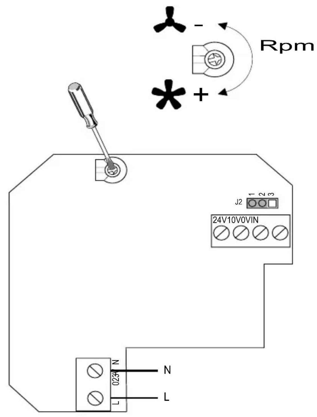
- The propeller turns in the correct direction.
• There are no abnormal vibrations. - If any of the electrical safety devices blow, the apparatus must be quickly disconnected from the mains supply. The whole installation should be carefully checked before trying to start up the machine again.
MAINTENANCE
- Before manipulating the ventilator, make sure it is disconnected from the mains supply even if it has previously been switched off. Prevent the possibility of anyone else connecting it while it is being manipulated.
- The apparatus must be regularly inspected. These inspections should be carried out bearing in mind the machine's working conditions, in order to avoid dirt or dust accumulating on the propeller, turbine, motor or grids. This could be dangerous and perceptibly shorten the working life of the ventilator unit.
- While cleaning, great care should be taken not to unstable the propeller or turbine.
- All maintenance and repair work should be carried out in strict compliance with each country's current safety regulations.
PUTTING OUT OF SERVICE AND RECYCLING
EEC legislation and our consideration of future generations mean that we should always recycle materials where possible; please do not forget to deposit all packaging in the appropriate recycling bins. If your device is also labeled with this symbol, please take it to the nearest Waste Management Plant at the end of its servicable life.
If you have any queries about S&P products, please contact our after-sales service in Spain, or your local S&P dealer in any other country. If in doubt, please visit our Web-Page at www.solerpalau.com
FRANÇAIS
TRANSPORTE E MANUSEIO


- TD-160/100
- TD-250/100, 350/125
- TD-500/150, TD-500/160, TD-800/200
- ESPAÑOL
- TRANSPORT AND MANIPULATION
- IMPORTANT INFORMATION FOR THE SAFETY OF INSTALLERS AND USERS
- SAFETY DURING INSTALLATION
- STARTING UP
- When starting up the machine, make sure that:
- MAINTENANCE
- PUTTING OUT OF SERVICE AND RECYCLING
- FRANÇAIS
- TRANSPORTE E MANUSEIO
Brand : Soler & Palau
Model : TDECOWATT
Category : Fan