Exacool - Fridge GYS - Free user manual and instructions
Find the device manual for free Exacool GYS in PDF.

User questions about Exacool GYS
0 question about this device. Answer the ones you know or ask your own.
Ask a new question about this device
Download the instructions for your Fridge in PDF format for free! Find your manual Exacool - GYS and take your electronic device back in hand. On this page are published all the documents necessary for the use of your device. Exacool by GYS.
USER MANUAL Exacool GYS
natural_image
Technical line drawing of three industrial electrical equipment units with cooling fans and heating elements (no text or symbols)FR 2 / 3-10 / 51-56
EN 2 / 11-18 / 51-56
DE 2 / 19-26 / 51-56
NL 2 / 27-34 / 51-56
IT 2 / 35-42 / 51-56
ES 2 / 43-50 / 51-56
NEOCOOL
EXACOOL
WCU1KW C
TWINCOOL
FIG-1
TWINCOOL
natural_image
Pure diagram of a curved black line with two endpoints and a numbered circle (7) pointing to one end, no text or symbols present.AVERTISSEMENTS - RÈGLES DE SÉCURITÉ
CONSIGNE GÉNÉRALE


INSTALLATION – FONCTIONNEMENT PRODUIT
| 2 | 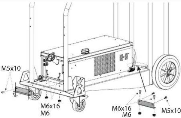 | 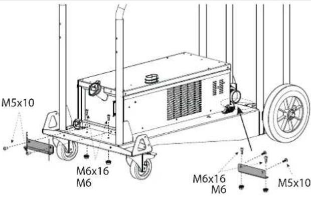 |
| 3 | 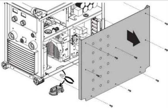 | 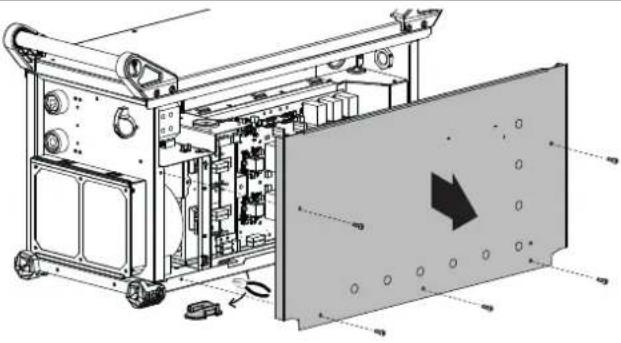 |
| 4 | 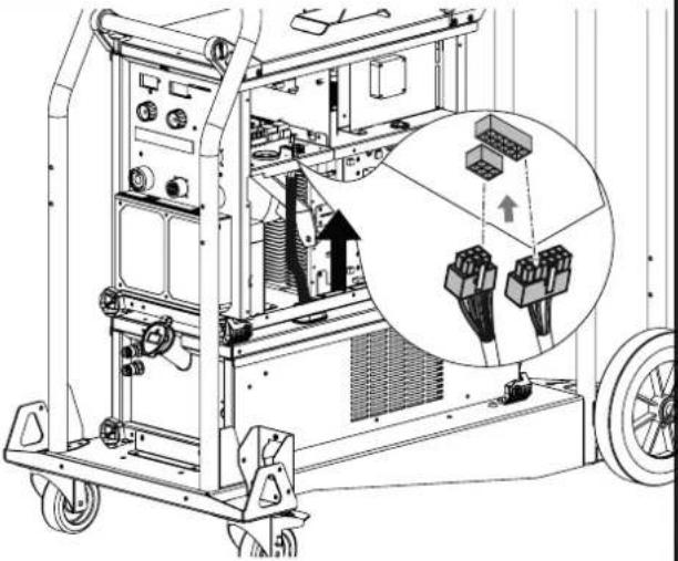 | 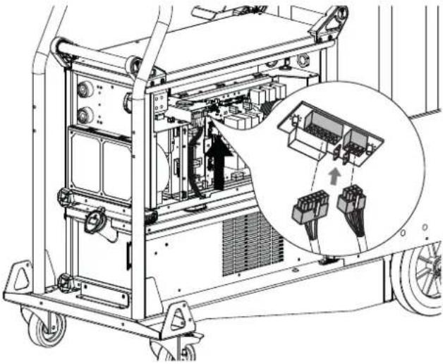 |
| 5 | 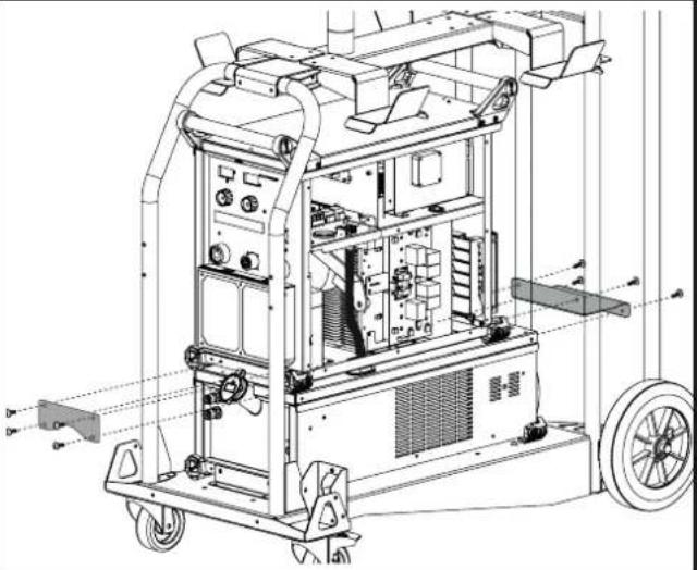 | 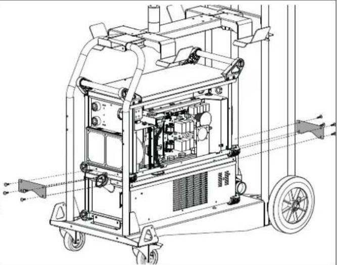 |

natural_image
Technical line drawing of an industrial machine with internal components and directional arrows indicating movement (no text or symbols present)WCU 1kW C (NEOPULSE 320 C)

natural_image
Technical line drawing of a mechanical device with mounting flanges and control panel (no text or symbols)
natural_image
Technical line drawing of a mechanical device with control panel and buttons (no text or symbols)
natural_image
Pure electrical circuit lines without any symbols
natural_image
Technical line drawing of an industrial electrical enclosure with cooling fans and a coiled cable (no text or symbols)Read and understand the following safety instructions before use.
Any modification or updates that are not specified in the instruction's manual should not be undertaken.
The manufacturer is not liable for any injury or damage due to non-compliance with the instructions featured in this manual.
If there is any issue or uncertainty, please consult a qualified person to handle the installation correctly.
ENVIRONMENT
This equipment must only be used for welding operations in accordance with the limits indicated on the information panel on the machine and/or in the instructions. Safety instructions must be followed. In case of improper or unsafe use, the manufacturer cannot be held liable.
This equipment must be used and stored in a room free from dust, acid, flammable gas or any other corrosive agent. Operate the machine in an open or well-ventilated area.
Operating temperature:
Use between -10 and +40°C (+14 and +104°F).
Storage between -20 and +55°C (-4 and 131°F).
Air humidity:
Lower or equal to 50% at 40°C (104°F).
Lower or equal to 90% at 20°C (68°F).
Altitude: Up to 2000 meters above sea level (6500 feet).
INDIVIDUAL PROTECTION & OTHERS
Arc welding can be dangerous and can cause serious injury or even death.
Welding exposes the user to dangerous heat, arc rays, electromagnetic fields, risk of electric shock, noise and gas fumes. People wearing pacemakers are advised to consult a doctor before using the welding machine. Protect yourself and others. Ensure the following safety precautions are taken:

In order to protect you from burns and radiations, wear clothing without cuffs. These clothes must be insulating, dry, fireproof, in good condition, and cover the whole body.

Wear protective gloves which guarantee electrical and thermal insulation.

Wear welding protective gear for the whole body: hood, gloves, jacket, trousers... (variable, depending on the application). Protect your eyes during cleaning procedures. Contact lenses are prohibited during use. It may be necessary to install fireproof welding curtains to protect the area against arc rays, weld spatter and sparks. Inform people who are around the working area to never look at the arc ray or the molten metal, and to wear protective clothes.

Wear ear protection if the work exceeds the authorised noise limit. The same applies to anyone in the welding area.
Keep hands, hair and clothes away from moving parts such as fans, and engines.
Never remove the safety covers from the cooling unit when the machine is plugged in. The manufacturer is not liable for any injury or damage due to non-compliance with the safety precautions.
Parts that have just been welded will be hot and may cause burns when touched. During the maintenance of the torch, make sure that the torch has sufficiently cooled down and wait at least 10 minutes before any operation. When using a water-cooled torch, make sure that the cooling unit is switched on to avoid any burns that could potentially be caused by the liquid. It is important to secure the working area before leaving it to ensure protection of the goods and the safety of people.
WELDING FUMES AND GAS

Fumes, gas and dust produced during welding are hazardous to health. It is mandatory to ensure adequate ventilation and/or extraction to keep fumes and gas away from the work area. Using an air fed welding helmet is recommended in case of insufficient ventilation in the workplace.
Check that the air supply is effective by referring to the recommended safety regulations.
Precautions must be taken when welding in small areas, and the operator will need supervision from a safe distance. Welding specific pieces of metal containing lead, cadmium, zinc, mercury or beryllium can be extremely toxic. The user will also need to remove the grease from the workpiece before welding.
Gas cylinders must be stored in an open or ventilated area. They must be stored vertically and held by a support or trolley to limit the risk of fall.
Do not weld in areas where grease or paint are stored.
FIRE AND EXPLOSION RISKS

Protect the entire welding area. Flammable materials must be moved to a minimum safe distance of 11 meters.
A fire extinguisher must be readily available near the welding operations.
Be careful of spatter and sparks, even through cracks.
It can be the source of a fire or an explosion.
Keep people, flammable materials/objects and containers that are under pressure at a safe distance.
Welding in closed containers or pipes should be avoided and, if they are opened, they must be emptied of any flammable or explosive material (oil, fuel, gas ...).
Grinding operations should not be directed towards the device itself or any flammable materials.
ELECTRICAL SAFETY

The electrical mains used must have an earth terminal. Use the recommended fuse size.
An electric shock could cause serious injuries or potentially even deadly accidents.
Never touch live parts inside and outside of the device when it is powered on (Torches, clamps, cables, electrodes) as they are connected to the welding circuit.
Before opening the device, it is imperative to disconnect it from the mains and to wait for 2 minutes in order for the capacitors to release the energy. Do not touch the torch or electrode holder and the earth clamp at the same time.
Be sure to change the cables and torches if they are damaged, to be performed by qualified and authorized personnel.
The dimensions and rating of the accessories must be suitable.
Always wear dry clothes which are in good condition in order to be isolated from the welding circuit. Always wear insulated shoes, regardless of the environment in which you work in.
TRANSPORTATION OF THE MACHINE

It is preferable to drain the cooling unit before transport.
Do not place/carry the unit over people or objects.
EQUIPMENT INSTALLATION
Rules to follow:
- Put the machine on the floor (maximum incline of 10^ .)
- Ensure the work area has sufficient ventilation for welding, and that there is easy access to the control panel.
- The machine must be placed in a sheltered area away from rain or direct sunlight.
- This equipment must be used and stored in a place protected from dust, acid, gas or any other corrosive substance.
- The machine protection level is IP23, which means :
- Protection against access to dangerous parts from solid bodies of a ≥12.5mm diameter and,
- Protection against the rain inclined at 60% towards the vertical.
The equipment can be used outside in accordance with the IP23 protection certification.

The manufacturer GYS does not incur any responsibility regarding damages to both objects and persons that result from an incorrect and/or dangerous use of the machine.
MAINTENANCE / RECOMMENDATIONS


- Maintenance should only be carried out by a qualified person. A yearly maintenance is recommended.
-
Ensure the machine is unplugged from the mains, and then wait 2 minutes before carrying out maintenance work. Inside, voltages and currents are high and dangerous.
-
Remove regularly the casing and any excess of dust. Take this opportunity to have the electrical connections checked by a qualified person, with an insulated tool.
- Regularly check the condition of the power supply cable. If the power cable or connection cables are damaged, they must be replaced by the manufacturer, its after sales service or an equally qualified person to prevent danger.
- Ensure the ventilation holes of the device are not blocked to allow adequate air circulation.
The cooling liquid must be changed every 12 month in order to avoid sediments which could block the torch cooling circuit. Any leak or residual fluid, after use, must be handled within the appropriate purification factory. If possible, recycle the product. It is prohibited to empty the product in a river, a sceptic tank or a draining system. The diluted fluid must not be emptied in the sewers, unless authorised by the local regulations.
INSTALLATION – PRODUCT OPERATION
Only qualified personnel authorised by the manufacturer should perform the installation of the welding equipment. During the installation, the operator must ensure that the machine is disconnected from the mains. Connecting generators in serial or in parallel is forbidden.
EQUIPMENT DESCRIPTION
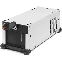
The EXACOOL cooling unit is a system designed to cool the water cooled torches connected to your EXAGON 400CC/CV welding machine.
The NEOCOOL cooling unit is a system designed to cool the water cooled torches connected to your NEOPULSE 400/500 G welding machine equipped with a Neofeed.
The TWINCOOL cooling unit is a system designed to cool the water cooled torches connected to your NEOPULSE 400/500 G welding machine. Equipped with two Neofeed.
The WCU1KW cooling unit is a system designed to cool the water cooled torches connected to your TITAN 400 / TITANIUM / NEOPULSE 320C welding machines.
These devices are controlled directly by the welding machine via two connection cables (FIG 1-6).
The NEOCOOL/TWINCOOL and the WCU1KW C are equipped:
- with a water level protection making sure the filling is at the minimum level for the good functioning of the cooling system but also for a good torch cooling.
- with a water flow protection in order to protect the torch against a blockage at the level of the water circuit or a damage of the torch connection. The NEOCOOL/TWINCOOL, the EXACOOL and the WCU1KW C are equipped with a thermal protection to prevent the torch for overheating abnormally.
The recommended cooling system units are automatically detected by the machine.
EXACOOL / WCU 1kW C :
In the « Setup memory » menu of the wire feeder EXAFEED, the EXACOOL can be inhibited.
In the « Setup/CONFIG » menu of the TITAN 400, the WCU 1kW C can be inhibited.
NEOCOOL / TWINCOOL / WCU 1kW C :
NEOCOOL / WCU 1kW C :
- AUTO: activation during welding and deactivation of the cooling unit 10 minutes after the end of welding.
- ON: the cooling unit is permanently controlled.
- OFF: the cooling unit is disabled.
- PURGE : function dedicated to purging the cooling unit or filling the connection cables. The protections are then disabled.
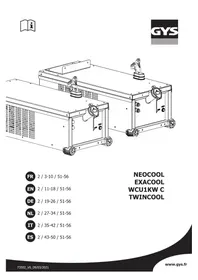
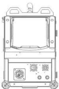
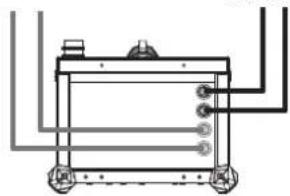
DESCRIPTION OF THE EQUIPMENT (I)
1- Coolant outlet 4- Fuse
2- Coolant inlet 5- Filling cap
3- Tank level indicator 6- Harnesses pre-cables
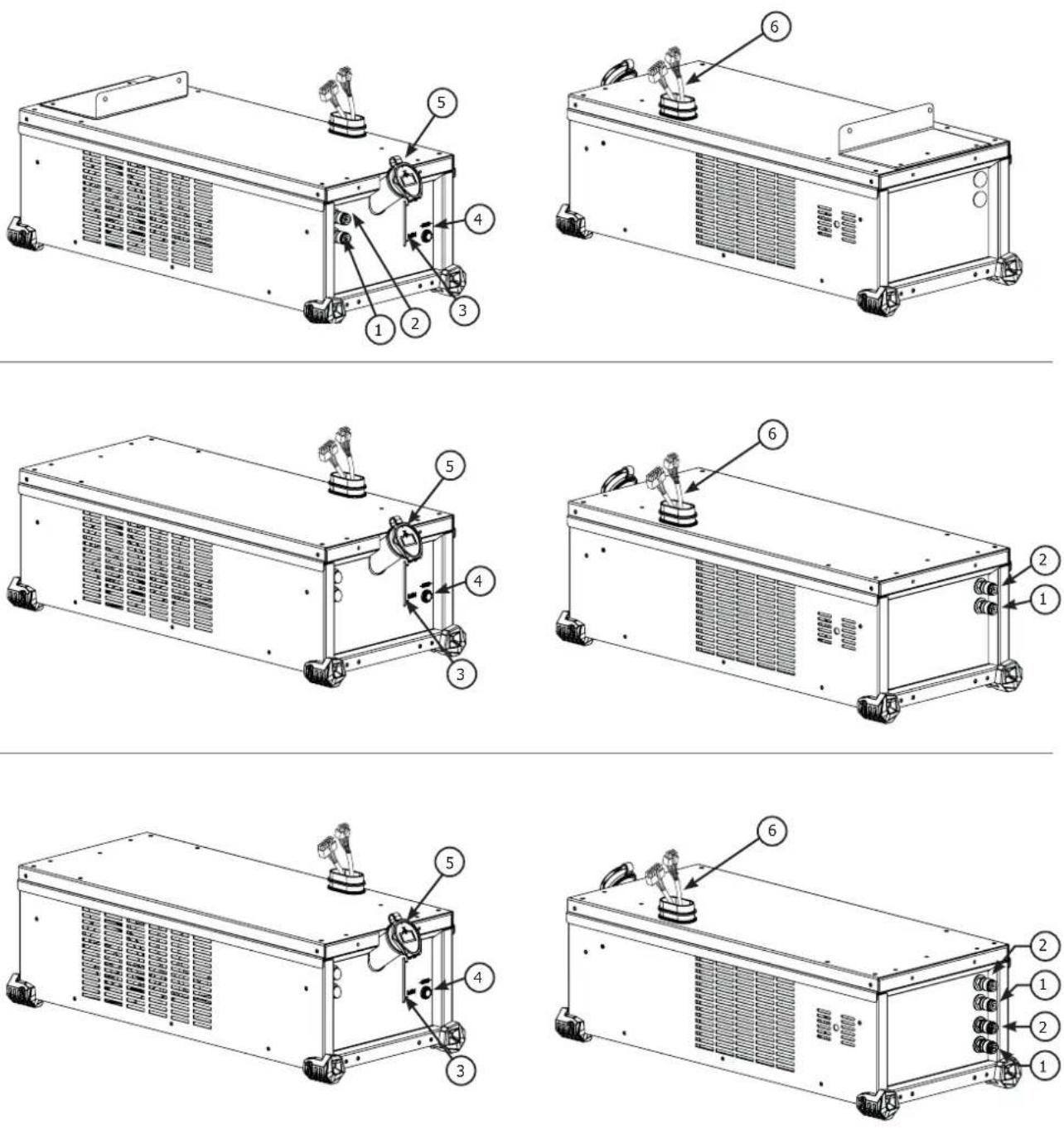
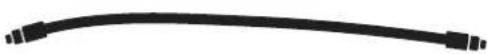
7- Starter pipe
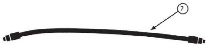
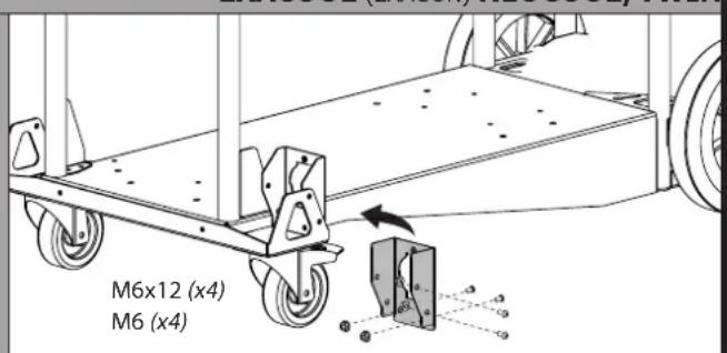
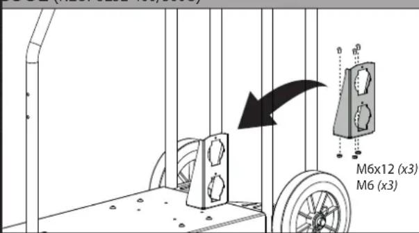
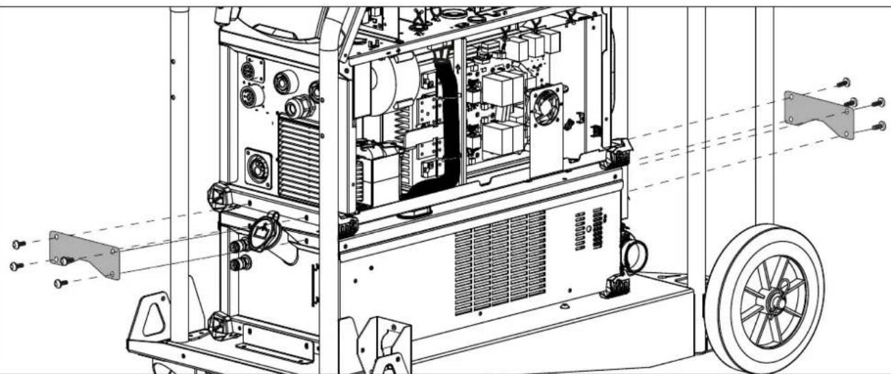
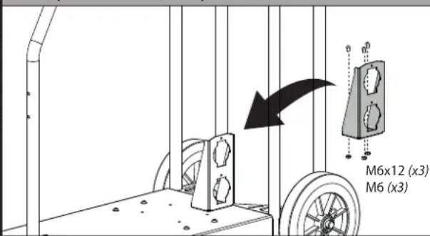
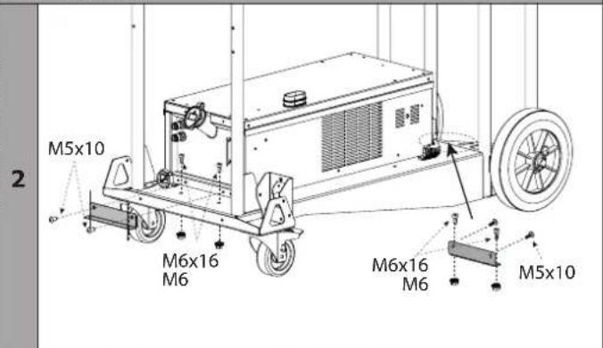
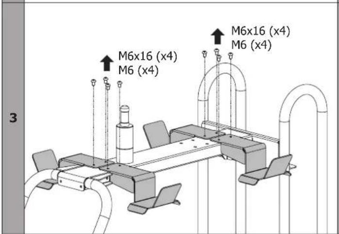
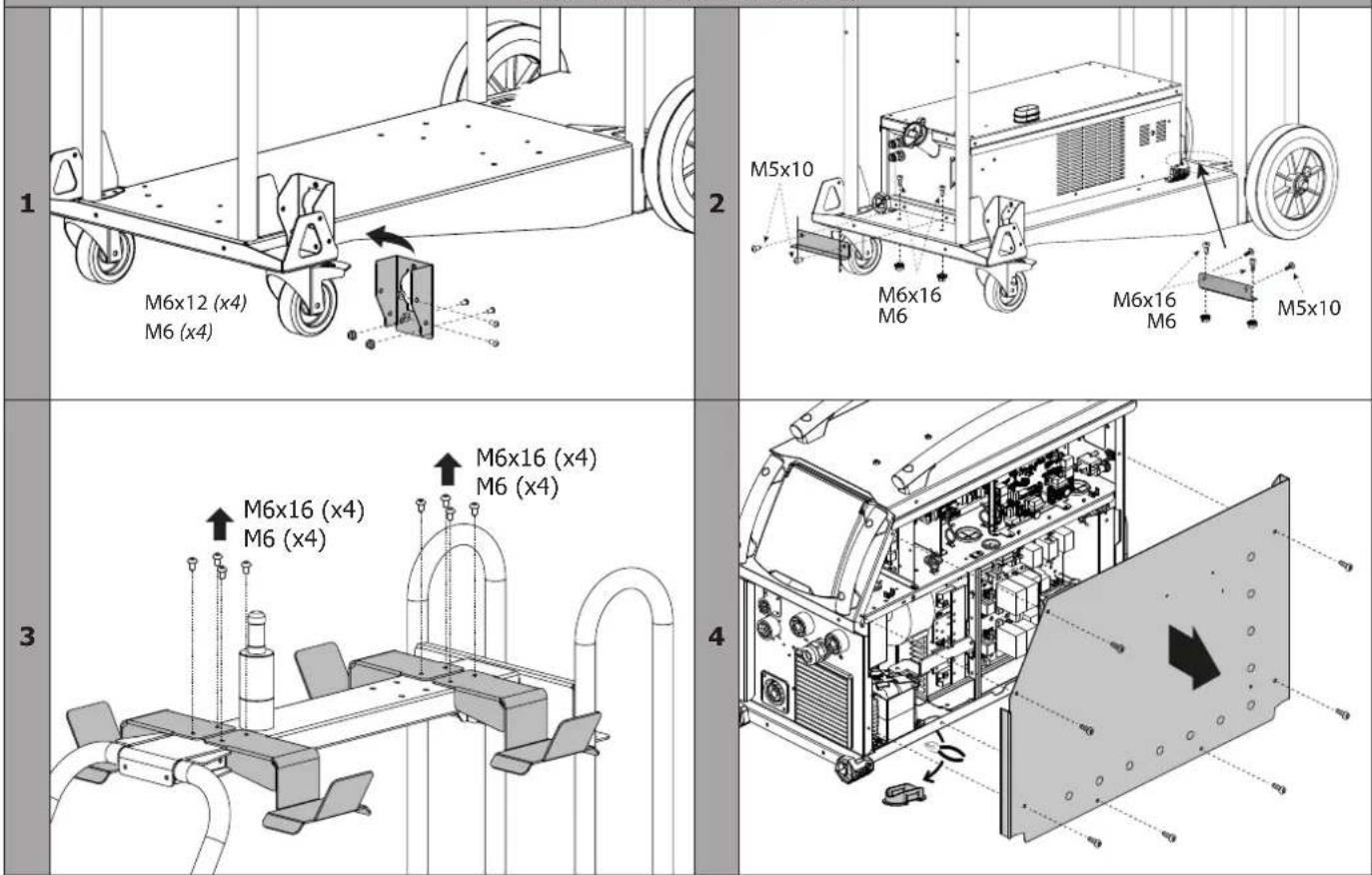
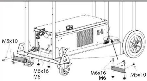
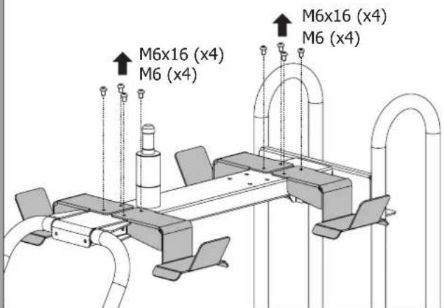
TROLLEY SET-UP (OPTION REF. 037328)

Warning! Do not connect the cooling unit whilst the welding machine is switched on.
EXACOOL (EXAGON) NEOCOOL/TWINCOOL (NEOPULSE 400/500G)
1
| 2 | | |
| 3 | | |
| 4 | | |
| 5 | 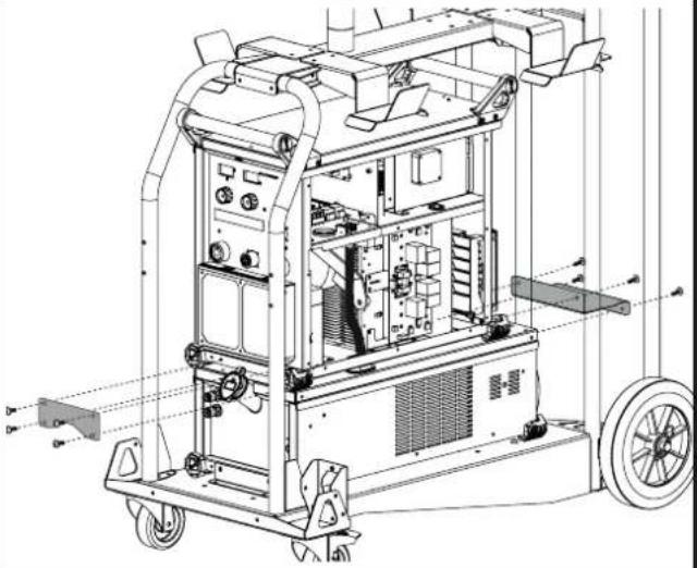 | 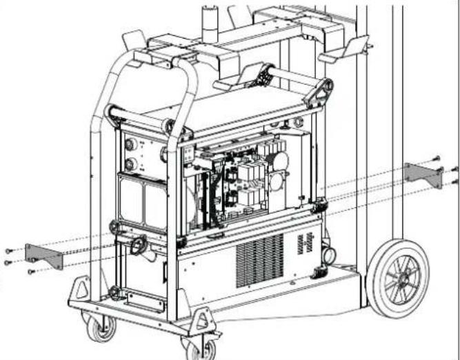 |

natural_image
Technical line drawing of an industrial machine with internal components and directional arrows indicating movement (no text or symbols present)WCU 1kW C (NEOPULSE 320 C)

5

natural_image
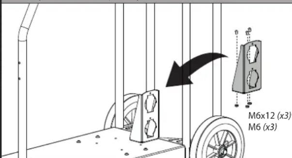
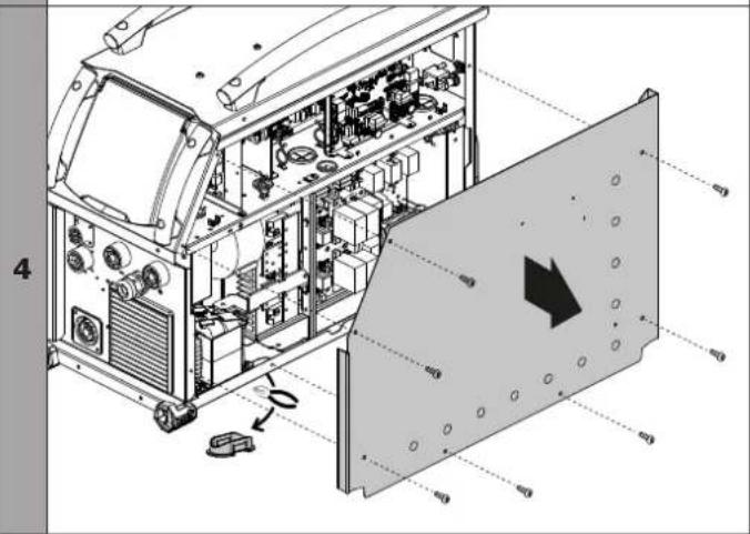
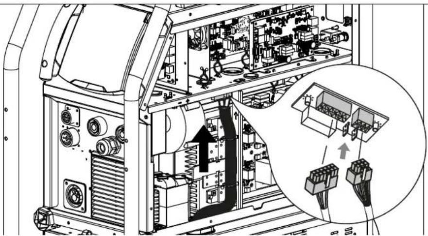
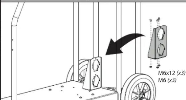
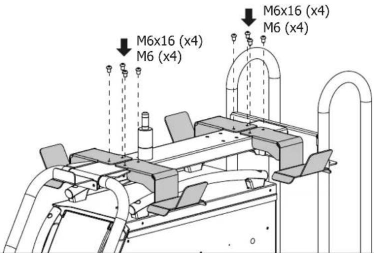
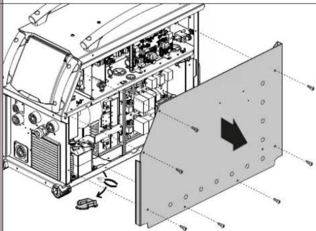
Technical diagram of an electronic device showing internal components and wiring, with a magnified inset highlighting connector connections (no text or labels present)Tilt the generator in order to make it easier for the harnesses to pass through its bulkhead. Check that the rubber grommet is properly positioned (prevents cable contact with the metal) and connect the harnesses.
6
natural_image
Technical line drawing of an industrial machine with visible internal components and external assembly (no text or labels)7

natural_image
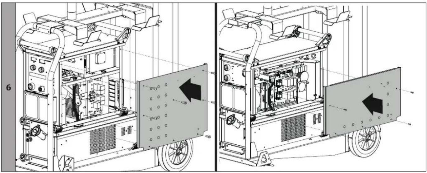
Technical line drawing of an industrial machine with internal components and a directional arrow indicating flow or movement (no text or symbols present)8

COOLANT

Make sure that the cooling unit is turned off before disconnecting the liquid inlet and/or outlet hoses of the torch. The coolant is harmful and can irritate the eyes and skin. Hot liquid may cause burns.
Risk of burns due to hot liquid. Never drain the cooling unit immediately after use. The liquid contained inside is boiling, wait until it cools down before draining.
FILLING
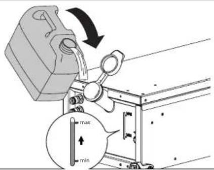
The operator must fill the tank up to its maximum indicated on the front of the cooling unit but never under the minimum line or a warning message will be displayed on the screen. It is essential to use a specific welding coolant with low electrical conductivity, being anticorrosive and anti-freezing (ref. 052246).
The use of any other coolant (in particular the automotive standard coolant), can lead, by electrolysis effect, to the accumulation of solid deposits in the cooling system, thus damaging it and also blocking the circuit.
This recommended maximum level is essential to optimise the duty cycles of the cooled torch. Any damage to the machine due to the use of a different coolant than the recommended type will not be covered by the guarantee.
TWINCOOL CONNECTION
natural_image
Technical line drawing of a mechanical device with front panel and control buttons (no text or symbols)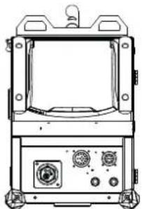
natural_image
Technical line drawing of a mechanical device with control panel and buttons (no text or symbols)
Follow the connection diagram shown to avoid damaging the lamp. The wire number is indicated on the interface.
Example: Wire feeder no.1
natural_image
Pure technical diagram of a mechanical or electrical component with no visible text, numbers, or symbols.
COLD UNIT START-UP
For the first application, the pump start-up could be difficult and generate a defect water flow. To start it correctly, it is recommended to use the above hose and follow the instructions below to purge the system:

Fill the cooling unit to its maximum level to facilitate priming.
EXAGON / TITAN :
- Connect the quick coupling to the cold water outlet of the unit and place the other end in an empty container (ideally a bottle)
- Connect a torch to the product, then briefly squeeze the trigger to start the pump
- Once the pump is activated (container that fills with coolant), stop the product by turning off the main welding generator switch.
- Disconnect the start pipe, put the liquid back into the cooling unit and connect the beam correctly (see user manual of the welding generator).
TITANIUM / NEOPULSE / NEOFEED :
- Connect the quick coupling to the cold water outlet of the unit and place the other end in an empty container (ideally a bottle)
- In the « Settings/Cooling unit » menu, press the icon to start the start-up procedure.
- Once the pump activated (container that fills with coolant), stop the cooling unit by pressing one of the buttons on the HMI.
- Disconnect the starting pipe, put the liquid back into the cooling unit: your pump is started.
natural_image
Technical line drawing of an industrial electrical enclosure with cooling fans and a coiled cable (no text or symbols)Long periods without use and impurities in the coolant can cause the cooling pump to jam. Pump shaft priming procedure:
1/ Switch off the power source.
2/ Insert a flat head screwdriver (∅ 9 mm max.) in the center of the pump shaft, passing through the service hole. Then turn the screwdriver clockwise until the pump shaft rotates smoothly again.
3/ Remove the screwdriver.
4/ Switch on the power source.
TROUBLESHOOTING
These devices integrate a default management system.
This allows the operator to diagnoses errors and anomalies. Refer to the instruction manual of the welding machine or the wire feeder (Troubleshooting chapter).
WARRANTY
The warranty covers faulty workmanship for 2 years from the date of purchase (parts and labour).
The warranty does not cover:
- Transit damage.
- Normal wear of parts (eg. : cables, clamps, etc..).
- Damages due to misuse (power supply error, dropping of equipment, disassembling).
- Environment related failures (pollution, rust, dust).
In case of failure, return the unit to your distributor together with:
- The proof of purchase (receipt etc ...)
- A description of the fault reported
5
natural_image
Technical diagram of an electronic device showing internal components and wiring, with a magnified inset highlighting connector connections (no text or labels present)natural_image
Technical line drawing of an industrial machine with visible internal components and external assembly (no text or labels)7
natural_image
Technical line drawing of an industrial machine with internal components and a directional arrow indicating flow or movement (no text or symbols present)8

natural_image
Technical line drawing of a mechanical device with front panel and control buttons (no text or symbols)
natural_image
Technical line drawing of a mechanical device with control panel and buttons (no text or symbols)
natural_image
Pure electrical circuit lines without any symbols
natural_image
Technical line drawing of a mechanical device with cooling fins and mounting tabs (no text or symbols)WAARSCHUWINGEN - VEILIGHEIDSINSTRUCTIES
ALGEMENE INSTRUCTIES
| 2 | | |
| 3 | | |
| 4 | | |
| 5 | | 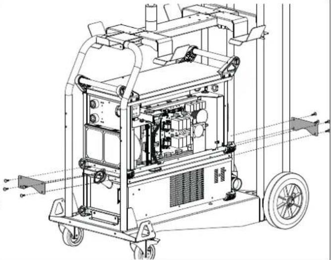 |
natural_image
Technical line drawing of an industrial machine with internal components and directional arrows indicating movement (no text or symbols present)WCU 1kW C (NEOPULSE 320 C)
5

natural_image
Technical diagram of an electronic device showing internal components and wiring, with a magnified inset highlighting connector connections (no text or labels present)natural_image
Technical line drawing of an industrial machine with visible internal components and external assembly (no text or labels)7

natural_image
Technical line drawing of an industrial machine with internal components and a directional arrow indicating flow or movement (no text or symbols present)8

KOELVLOEISTOF
natural_image
Technical line drawing of a mechanical device with mounting flanges and control panel (no text or symbols)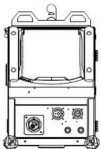
natural_image
Technical line drawing of a mechanical device with control panel and buttons (no text or symbols)
natural_image
Pure electrical circuit lines without any symbols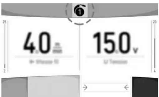
OPSTARTEN VAN DE KOELGROEP

natural_image
Technical line drawing of a mechanical device with cooling fins and a handle (no text or symbols)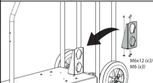
| 2 | | |
| 3 | | |
| 4 | | |
| 5 | | |

natural_image
Technical line drawing of an industrial machine with internal components and directional arrows indicating movement (no text or symbols present)WCU 1kW C (NEOPULSE 320 C)

5

natural_image
Technical diagram of an electronic device showing internal components and wiring, with a magnified inset highlighting connector connections (no text or labels present)natural_image
Technical line drawing of an industrial machine with internal components and a wheel (no text or symbols)7

natural_image
Technical line drawing of an industrial machine with internal components and a directional arrow indicating flow or movement (no text or symbols present)8
natural_image
Technical line drawing of a mechanical device with control panel and buttons (no text or symbols)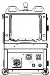
natural_image
Technical line drawing of a mechanical device with control panel and buttons (no text or symbols)
natural_image
Pure electrical circuit lines without any symbols
natural_image
Technical line drawing of an industrial electrical enclosure with cooling fins and mounting tabs (no text or symbols)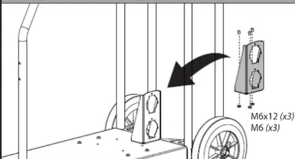
2
3
4
natural_image
Technical line drawing of a mechanical device with mounting flanges and control panel (no text or symbols)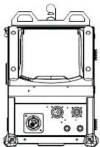
natural_image
Technical line drawing of a mechanical device with control panel and buttons (no text or symbols)
natural_image
Pure electrical circuit lines without any symbols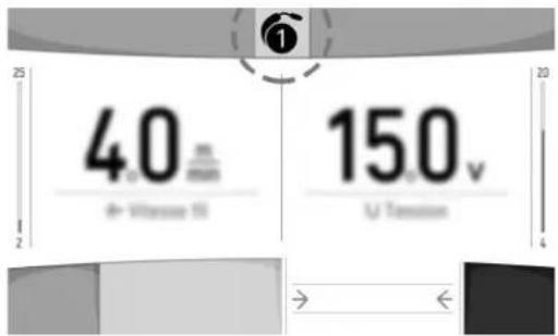
natural_image
Technical line drawing of an industrial electrical enclosure with cooling fins and a handle (no text or symbols)| EXACOOL 032422 032750 013537 065086 | NEOCOOL WCU1KW C TWINCOOL | |||
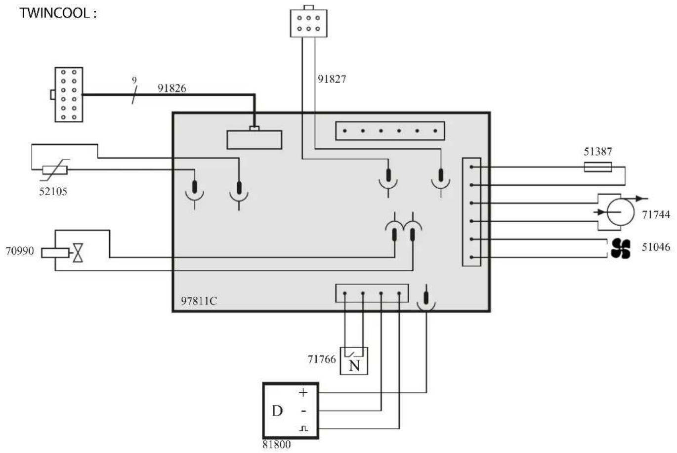
| 1 | Pompe 10L/min 400V 50/60 Hz / Pump 10L/min 400V 50/60 Hz / Помпа 10л/мин 400В 50/60 Гц / Pompa 10L/min / Pomp 10L/min / 泵 / Bomba 10L/min | 71744 | ||
| 2 | Patin / Shield / Подошва / Distanziale/pattino / Beschermkapje / 保护物 / Soporte | 56120 | ||
| 3 | Raccord Rapide Bleu / Quick Coupling Blue | 71694 (x1) | 71694 (x2) | |
| 3 | Raccord Rapide Rouge / Quick Coupling Red | 71695 (x1) | 71695 (x2) | |
| 4 | Bouchon de remplissage / Fill plug / Пробка заправочного отверстия / Tappo del serba-toio / Vuldop / 填塞 / Tapón de envase | 71299 | ||
| 5 | Réservoir 5.5l / 5.5L tank / Бак 5.5л / Serbatoio 5.5L / Reservoir 5.5L / 5.5L水箱 / Reserva 5.5L | 90915 90861 90861 M0136 | ||
| 6 | Capteur de niveau d'eau / Water level sensor / Датчик уровня жидкости / Sensore del livello dell'acqua / Sensor waterniveau / 水位指示传感器 / Sensor de nivel de agua | -71766 | ||
| 7 | Capteur de débit d'eau / Water flow sensor / Датчик расхода жидкости / Sensore del flusso dell'acqua / Sensor waterdoorstroming / 水流量传感器 / Sensor de caudal de agua | -81100 | ||
| 8 | Faisceau 12pts / 12pts connection cable / Рукав 12 тчк / Fascio cavo 12pts / 12-polige kabel / 12pts的接地电缆 / Cable 12pts | 91826 | ||
| 9 | Faisceau 6pts / 6pts connection cable / Рукав 6 тчк / Fascio cavo 6pts / 6-polige kabel / 6pts的接地电缆 / Cable 6pts | 91827 | ||
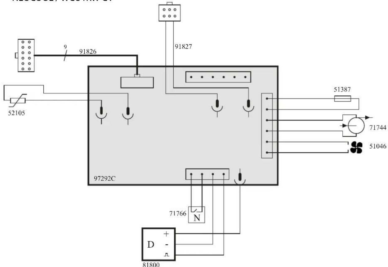
| 10 | Circuit groupe froid / Cooling unit circuit / Цепь системы охлаждения / Circuito unità di raffreddamento / Circuit koelgroep / 冷却装置电路 / Circuito equipo de refrigeración | 97772C 97292C | 97292C | 97811C |
| 11 | Radiateur eau / Water radiator / Радиатор жидкости / Radiatore acqua / Radiator water / 水散热器 / Radiador de agua | 71778 | ||
| 12 | Ventilateur / Fan / Вентилятор / Ventilatore / Ventilator / 风扇 / Ventilador | 51046 | ||
| 13 | Porte fusible / Fuse holder / Сменный патрон плавкого предохранителя / Porta fusibile / Zekeringhouder / 保险丝座 / Porta fusible | 51387 | ||
| 14 | Fusible / Fuse / Плавкий предохранитель / Fusibile / Zekering / 保险丝 / Fusible | 51401 | ||
| 15 | Capteur de température / Temperature sensor / Температурный датчик / Sensore di temperatura / Temperatuursensor / 温度传感器 / Sensor de temperatura | 52105 | ||
| 16 | Électrovanne double sorties / Double output solenoid valve / Magnetventil-Doppelaus-gänge / Válvula solenoide tiene doble salida / Электромагнитный клапан двойные выходы / Magneetventiel dubbele uitgangen / Elettrovalvola a doppia uscita | -70990 | ||
SCHÉMAS ÉLECTRIQUES / ELECTRIC DIAGRAM / ЭЛЕКТРИЧЕСКИЕ СХЕМЫ / SCHEMI ELETTRICI / ELEKTRISCHE SCHEMAS / 电气图 / ESQUEMAS ÉLECTRICOS
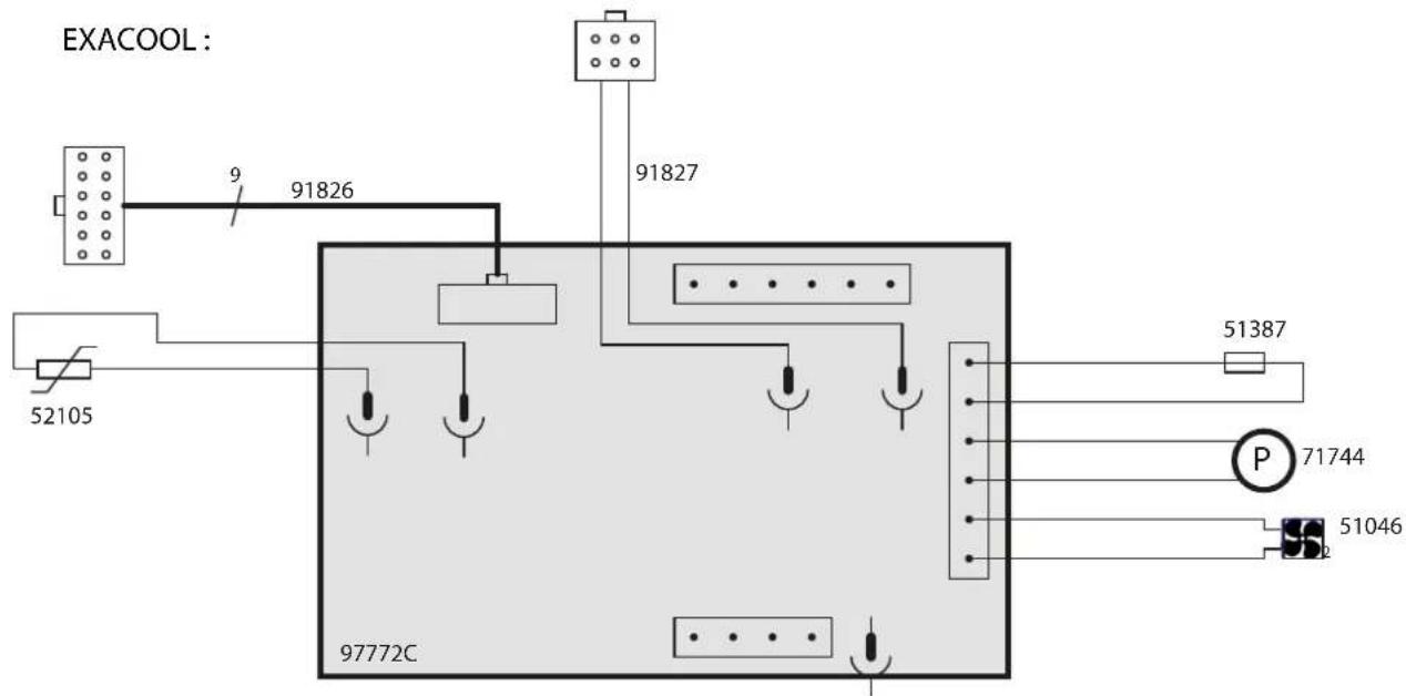
NEOCOOL / WCU1KW C :
SPÉCIFICATIONS TECHNIQUES / TECHNICAL SPECIFICATIONS / TECHNISCHE DATEN / TEXНИЧЕСКИЕ СПЕЦИФИКАЦИИ / SPECIFICHE TECNICHE / TECHNISCHE GEGEVENS / 技术规范
| GROUPE FROID / COOLING UNIT / СИСТЕМА ОХЛАЖДЕНИЯ /UNITÀ DI RAFFREDDAMENTO / KOELGROEP / 冷却装置 / Equipo derefrigeración | EXACOOL NEOCOOL WCU1KW C TWINCOOL | ||
| Modèle / Reference / Модель / Modello / Model / 编号 / Modelo | CC/CV WCU | DIGITAL CONTROL WCU | |
| Primaire / Primary / Primär / Первичка / Primario / Primaire / 初级 / Primario | |||
| Tension d'alimentation / Power supply voltage / Stromversorgung /Напряжение питания / Tensione di alimentazione / Voedingsspanning / 电源电压 / Tensión de red eléctrica | 400 V +/- 15% | ||
| Fréquence secteur / Mains frequency / Netzfrequenz / Частота сети /Frequenza settore / Frequentie sector / 电源频率 / Frecuencia | 50 / 60 Hz | ||
| Fusible disjoncteur / Fuse / Sicherung / Плавкий предохранительпрерывателя / Fusibile disgiuntore / Zekering hoofdschakelaar / 保险丝 /Fusible disyuntor | 5 A | ||
| Puissance de refroidissement à 1l/min à 25°C / Cooling power at 1l/min at25°C / Мощность охлаждения 1 л/мин при 25°C / Potenza di raffreddamento a 1l/min à 25°C / Koelvermogen 1l/min bij 25°C / 冷却功率25摄氏度时1升/分钟 / Potencia de refrigeración a 1l/min a 25°C | 1 kW | ||
| Facteur de correction à 40°C / Correction factor 40°C / Коэффициенткоррекции при 40°C / Ciclo di correzione a 40°C / Correctiefactor bij 40°C /40摄氏度时的校正系数 / Factor de corrección a 40°C | 0.58 | ||
| Pression maximale / Maximum pressure / Максимальное давление / Pres-sione massima / Maximale druk / 最大压力 / Presión máxima | 0.4 MPa(58 psi) | ||
| Capacité réservoir / Tank capacity / Füllmenge (Kühlflüssigkeit) / Емкость бака /Capacidad del tanque / Вместимость резервуара / Tankcapaciteit / Capacità delserbatoio | 5.5 l(1.45 gal US) | ||
| Température de fonctionnement / Functioning temperature / Betriebstemperatur /Рабочая температура / Temperatura di funzionamento / Gebruikstemperatuur / 运行温度 / Temperatura de funcionamiento | -10° → +40°C | ||
| Température de stockage / Storage temperature / Lagerungstemperatur /Температура хранения / Temperatura di stoccaggio / Bewaartemperatuur / 存储温度 / Temperatura de almacenaje | -20° → +55°C | ||
| Degré de protection / Protection level / Schutzgrad / Степень защиты / Grado diprotezione / Beschermingsklasse / 保护级别 / Grado de protección | IP23 | ||
| Dimensions (Lxlxh) / Dimensions (Lxlxh) / Abmessung (LxBxH) / Размеры (ДхШхВ)/ Dimensioni (Lxlxh) / Afmetingen (Lxbxh) / 规格 / Dimensiones (Lxlxh) | 68 x 30 x 23 cm | ||
| Poids / Weight / Gewicht / Bec / Peso / Gewicht / 重量 / Peso | 17 kg | 18 kg | |