Gysarc 300 TRI - Welding machine GYS - Free user manual and instructions
Find the device manual for free Gysarc 300 TRI GYS in PDF.
Document temporarily unavailable
The manual is currently being transferred to our new server. It will be accessible again in a few hours. Thank you for your patience.
| Brand | GYS |
| Model | Gysarc 300 TRI |
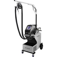
| Product type | Three-phase inverter arc welding machine |
| Welding processes | MMA (stick electrode), TIG-LIFT (tungsten inert gas welding) |
| Power supply | Three-phase 400V +/- 15%, 50-60 Hz, 16A plug type EN 60309-1 |
| MMA welding current range | 30 - 300 A (depending on electrode diameter) |
| TIG welding current range | 5 - 300 A (depending on tungsten electrode diameter) |
| Protection rating | IP23 (outdoor use possible) |
| Operating temperature | -10°C to +40°C |
| Storage temperature | -20°C to +55°C |
| Maximum humidity | ≤ 50% at 40°C, ≤ 90% at 20°C |
| Maximum altitude | 1000 m above sea level |
| Main settings | Welding current, Arc Force, Hot Start, MMA/TIG mode selection |
| Special functions | VRD (voltage reduction device <20V), Anti-Sticking, manual remote control (optional) |
| Display | Digital displays of voltage and current |
| Ventilation | Temperature-regulated ventilation, thermal protection with orange indicator light |
| Electromagnetic compatibility | Class A (industrial use), compliant with IEC 61000-3-11 |
| Supplied equipment | Power cable with 16A plug, carrying handles |
| Recommended maintenance | Regular dusting with compressed air, annual check of connections by qualified personnel |
| Warranty | 2 years (parts and labor) against manufacturing defects |
| Country of origin | France (manufactured by GYS, Saint-Berthevin) |
Frequently Asked Questions - Gysarc 300 TRI GYS
User questions about Gysarc 300 TRI GYS
0 question about this device. Answer the ones you know or ask your own.
Ask a new question about this device
Download the instructions for your Welding machine in PDF format for free! Find your manual Gysarc 300 TRI - GYS and take your electronic device back in hand. On this page are published all the documents necessary for the use of your device. Gysarc 300 TRI by GYS.