Gyspot Combi 230 E PRO - Generator GYS - Free user manual and instructions
Find the device manual for free Gyspot Combi 230 E PRO GYS in PDF.
| Product type | Resistance welding generator |
| Brand | GYS |
| Model | Gyspot Combi 230 E PRO |
| Power supply | 230 V single-phase, 50-60 Hz, 16 A CEE7/7 plug |
| Main functions | Dent removal of steel and aluminum car bodies by single-point and multi-point traction, welding of studs, stars, corrugated wire, rivets, washers |
| Welding types | Resistance welding (steel) and capacitor discharge welding (aluminum) |
| Adjustable power (steel) | Levels 1 to 9 |
| Adjustable power (aluminum) | Voltage 50-200 V or power L, 1-9, H |
| Thermal protection | Yes, with yellow indicator and temporary automatic shutdown |
| Operating temperature | -10°C to +40°C |
| Storage temperature | -20°C to +55°C |
| Maximum humidity | 50% at 40°C, 90% at 20°C |
| Maximum altitude | 1000 m |
| Maintenance | Regular dusting with a blower, checking electrical connections |
| Cleaning | Stripping of welding areas, cleaning tools before use |
| Safety | Mandatory personal protection (gloves, fireproof clothing, welding helmet), grounding, avoid electromagnetic fields |
| Spare parts | Cables, guns, electrodes, studs, copper tips, various tools |
| Repairability | Maintenance and repair only by the manufacturer or its after-sales service |
| Warranty | 2 years (France) against manufacturing defects (parts and labor) |
| Included accessories | Guns (with and without trigger), ground cable, tools (stars, dent puller pliers, carbon electrode, etc.) |
| Standards | Class A, not compliant with IEC 61000-3-12, professional use |
Frequently Asked Questions - Gyspot Combi 230 E PRO GYS
User questions about Gyspot Combi 230 E PRO GYS
0 question about this device. Answer the ones you know or ask your own.
Ask a new question about this device
Download the instructions for your Generator in PDF format for free! Find your manual Gyspot Combi 230 E PRO - GYS and take your electronic device back in hand. On this page are published all the documents necessary for the use of your device. Gyspot Combi 230 E PRO by GYS.
USER MANUAL Gyspot Combi 230 E PRO GYS
Read and understand the following safety instructions before use.
Any modification or maintenance not specified in the instructions manual should not be undertaken.
The manufacturer is not liable for any injury or damage due to non-compliance with the instructions featured in this manual. In the event of problems or uncertainties, please consult a qualified person to handle the installation properly.
These instructions cover the material in the condition it was delivered. It is the responsibility of the user to carry a risk analysis in case the instructions are not followed.
ENVIRONMENT
This equipment must only be used for welding operations in accordance with the limits indicated on the descriptive panel and/or in the user manual. Safety instructions must be followed. In case of improper or unsafe use, the manufacturer cannot be held liable.
This equipment must be used and stored in a room free from dust, acid, flammable gas or any other corrosive agent. The same rules apply for storage. Operate the machine in an open, or well-ventilated area.
Operating temperature:
Use between -10 and +40^ (+14 and +104^)
Storage between -20 and +55^ (-4 and 131^)
Air humidity:
Lower or equal to 50% at 40^ (104^)
Lower or equal to 90% at 20^ (68^)
Altitude:
Up to 1000 meters above sea level (3280 feet).
PROTECTION OF THE INDIVIDUALS
Resistance welding can be dangerous and cause serious injuries or even death. It needs to be used by a qualified technician with training relevant to the machine.
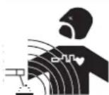
Welding exposes the user to dangerous heat, arc rays, electromagnetic fields, risk of electric shock, noise and gas fumes. People wearing pacemakers are advised to consult a doctor before using the welding machine.
To protect oneself as well as the other, ensure the following safety precautions are taken:

In order to protect you from burns and radiations, wear clothing without turn-up or cuffs. These clothes must be insulating, dry, fireproof, in good condition and cover the whole body.

Wear protective gloves which guarantee electrical and thermal insulation.

Use sufficient welding protective gear for the whole body: hood, gloves, jacket, trousers... (varies depending on the application/operation). Protect the eyes during cleaning operations. Contact lenses are prohibited during use.
It may be necessary to install fireproof welding curtains to protect others against arc rays, weld spatters and sparks. Ask people around the working area to look away from at the arc or the molten metal, and to wear protective clothing.

Ensure ear protection is worn by the operator if the work exceeds the authorised noise limit (the same applies to any person in the welding area).

Parts that have previously been welded will be hot and may cause burns if manipulated. During maintenance work on the torch or the electrode holder, you should make sure it's cold enough and wait at least 10 minutes before any intervention. When using a water-cooled torch, make sure that the cooling unit is switched on to avoid any burns caused by the liquid.
It is important to secure the working area before leaving to ensure the protection of property and the safety of others.
WELDING FUMES AND GAS

Fumes, gas and dust produced during welding are hazardous to health. It is mandatory to ensure adequate ventilation and/or extraction to keep fumes and gas away from the work area. Using an air fed welding helmet is recommended in case of insufficient ventilation in the workplace.
Check that the air supply is effective by referring to the recommended safety regulations.
Precautions must be taken when welding in small areas, and the operator will need supervision from a safe distance. In addition, the welding of certain materials containing lead, cadmium, zinc, mercury or beryllium may be particularly harmful. Also remove any grease on the metal pieces before welding. Do not weld in areas where grease or paint are stored.
FIRE AND EXPLOSION RISKS
Protect the entire welding area. Flammable materials must be moved to a minimum safe distance of 11 meters. A fire extinguisher must be readily available near the welding operations. Be careful of spatter and sparks, even through cracks. It can be the source of fire or explosion. Keep people, flammable materials/objects and containers that are under pressure at a safe distance.
Welding in closed containers or pipes should be avoided and, if they are opened, they must be emptied of any flammable or explosive material (oil, fuel, gas ...). Grinding operations should not be carried out close to the power supply or any flammable materials.
ELECTRICAL SAFETY

The electrical mains used must have an earth terminal. An electric shock could cause serious injuries or potentially even deadly accidents.
Never make contact with live parts inside or outside the current source (cables, electrodes, arms, guns...) as they are connected to the welding circuit. Before opening the device, it is imperative to disconnect it from the mains and wait 2 minutes, so that all the capacitors are discharged.
Damaged cables and torches must be changed by a qualified and skilled professional. Make sure that the cable cross section is adequate with the usage (extensions and welding cables). Always wear dry clothes which are in good condition in order to be isolated from the welding circuit. Wear insulating shoes, regardless of the workplace/environment in which you work in.
EMC CLASSIFICATION

This Class A machine is not intended to be used on a residential site where the electric current is supplied by the domestic low-voltage power grid. There may be potential difficulties in ensuring electromagnetic compatibility at these sites, due to conducted interferences as well as radiation.

This equipment does not comply with IEC 61000-3-12 and is intended to be connected to domestic low-voltage systems interfacing with the public supply only at the medium- or high-voltage level. If it is connected to a public low-voltage power grid, the installer or user of the machine has to ensure, by checking with the network operator, that the device can be connected.
ELECTROMAGNETIC INTERFERENCES
The electric currents flowing through a conductor cause electrical and magnetic fields (EMF). The welding current generates an EMF around the welding circuit and the welding equipment.
The EMF electromagnetic fields can interfere with certain medical implants, such as pacemakers. Protection measures must be taken for people having medical implants. For example, access restrictions for passers-by or an individual risk evaluation for the welders.
Each welder must follow the procedures below in order to minimise exposure to electromagnetic generated by the welding circuit:
- position the welding cables together - strap them if possible;
- keep your head and top half of the body as far from the welding circuit as possible;
- never enrol the cables around your body;
- never position your body between the welding cables. Hold both welding cables on the same side of your body;
- connect the earth clamp as close as possible to the area being welded;
- do not work too close to, do not lean and do not sit on the welding machine
- do not weld when you're carrying the welding machine or its wire feeder.

People wearing pacemakers are advised to consult their doctor before using this device. Exposure to electromagnetic fields while welding may have other health effects which are not yet identified.
RECOMMENDATIONS FOR EVALUATING THE WELDING AREA AND INSTALLATION
Miscellaneous
The user is responsible for the correct installation and usage of the welding material based on the instructions supplied by the manufacturer. If electromagnetic disturbances are detected, it is the user's responsibility to resolve the situation with the manufacturer's technical assistance. In some cases, this corrective action may be as simple as earthing the welding circuit. In other cases, it may be necessary to construct an electromagnetic shield around the welding power source and around the entire piece by fitting input filters. In all cases, electromagnetic interferences must be reduced until they are no longer inconvenient.
Welding area assessment
Before installing the machine, the user must evaluate the possible electromagnetic problems that may arise in the area where the installation is planned. The following must be taken into account:
a) the presence (above, below and next to the arc welding machine) of other power cables, remote cables and telephone cables;
b) television transmitters and receivers;
c) computers and other hardware;
d) critical safety equipment such as industrial machine protections;
e) the health and safety of the people in the area such as people with pacemakers or hearing aids;
f) calibration and measuring equipment;
g) the isolation of other pieces of equipment which are in the same area.
The user has to ensure that the devices and pieces of equipment used in the same area are compatible with each other. This may require extra precautions;
h) the time of day during the welding or other activities have to be performed.
The surface of the area to be considered around the device depends on the building's structure and other activities that take place there. The area taken into consideration can be larger than the limits of the installations.
Review of the welding installation
Reviewing the welding installations can be useful to determine and resolve any case of electrical disturbances. The assessment of emissions must include in situ measurements as specified in Article 10 of CISPR 11. In situ measurements can also be used to confirm the effectiveness of mitigation measures.
RECOMMENDATION ON METHODS OF ELECTROMAGNETIC EMISSIONS REDUCTION
a. National power grid: The arc welding machine must be connected to the national power grid in accordance with the manufacturer's recommendation. In case of interferences, it may be necessary to take additional precautions such as the filtering of the power supply network. Consideration should be given to shielding the power supply cable in a metal conduit or equivalent of permanently installed arc welding equipment. It is necessary to ensure the electrical continuity of the shielding along its entire length. The shielding should be connected to the welding current's source to ensure good electrical contact between the conduct and the casing of the welding current source.
b. Maintenance of the arc welding equipment: The arc welding machine should be subject to a routine maintenance check according to the recommendations of the manufacturer. All accesses, service doors and covers should be closed and properly locked when the arc welding equipment is on. The arc welding equipment must not be modified in any way, except for the changes and settings outlined in the manufacturer's instructions.
c. Welding cables: Cables must be as short as possible, close to each other and close to the ground, if not on the ground.
d. Equipotential bonding: consideration should be given to bonding all metal objects in the surrounding area. However, metal objects connected to the workpiece increase the risk of electric shock if the operator touches both these metal elements and the electrode. It is necessary to insulate the operator from such metal objects.
e. Earthing of the welded part: When the part is not earthed - due to electrical safety reasons or because of its size and its location (which is the case with ship hulls or metallic building structures), the earthing of the part can, in some cases but not systematically, reduce emissions It is preferable to avoid the earthing of parts that could increase the risk of injury to the users or damage other electrical equipment. If necessary, it is appropriate that the earthing of the part is done directly, but in some countries that do not allow such a direct connection, it is appropriate that the connection is made with a capacitor selected according to national regulations.
f. Protection and shielding: The selective protection and shielding of other cables and devices in the area can reduce perturbation issues. The protection of the entire welding area can be considered for specific situations.
TRANSPORT AND TRANSIT OF THE WELDING MACHINE

The welding source is fitted with a handle or strap to make it transportable by hand. Be careful not to underestimate the weight of the machine. The handle or strap are not design to be used to hang the machine to something else.
INSTALLATION OF THE EQUIPMENT
- Provide sufficient area to ventilate the welding power source and access the controls.
- Do not use in an environment with conductive metal dust.
- Power, extension and welding cables should be fully unwound to avoid overheating.

The manufacturer assumes no responsibility for damage to persons and objects caused by improper and dangerous use of this equipment.
MAINTENANCE / RECOMMENDATIONS


- The operators must have received suitable training in order to use the machine at its maximum potential and weld correctly.
-
Check which welding process is authorised by the manufacturer before attempting any vehicle repair.
-
The maintenance and the repair of the . Any work undertaken by a third party on the generator will invalidate the warranty. The manufacturer will not accept liability in the event of an incident that would occur after this work was undertaken.
- Ensure the machine is unplugged from the mains, and wait for two minutes before carrying out maintenance work. Inside, voltages and currents are high and dangerous.
- All the welding tools will wear off with use. Ensure that these tools are clean to get the best results.
- Prior to using the gun, check the condition of the different tools (star, single sided electrode, carbon electrode...) and clean or replace if required.
- Remove regularly the casing and any excess of dust. Take this opportunity to have the electrical connections checked by a qualified person, with an insulated tool.
- Regularly review the condition of the power cable and welding connection cables. In case of visible signs of damage, organise for them to be replaced by the manufacturer or a qualified technician.
- Ensure the vents of the device are not blocked to allow adequate air circulation.
ELECTRICITY SUPPLY
This equipment is supplied with a 16 A CEE7/7 type plug and must only be used in a single-phase 230V (50 - 60 Hz) three-wire electrical installation with a neutral conductor connected to earth.
The permanent absorbed current (I1p) indicated in the «electrical characteristics» section of this manual corresponds to the maximum operating conditions. Check that the power supply and its protection (fuse and/or circuit breaker) are compatible with the current required for use. In some countries, it may be necessary to change the plug to allow use under maximum conditions.
NB: If the product trips the circuit breaker, please check that the correct fuse and an adequate circuit breaker are being used.
- These are A-class devices. They are designed to be used in an industrial or professional environment. In a different environment, it can be difficult to ensure electromagnetic compatibility, due to conducted disturbances as well as radiation.
- From 1st December 2010, the new standard EN 60974-10 will be applicable: Warning: these materials do not comply with IEC 61000-3-12. If they are to be connected to a low-voltage main supply, it is the responsibility of the user to ensure they can be connected. If necessary consult the operator of your electrical distribution system.
Use of the aluminium generator: The COMBI 230 E PRO protects itself if the voltage exceeds 265V. The device prevents the charge of the capacitors. To indicate the failure, the 3 horizontal segments in the centre of the display light up.
Charge of the capacitors: A blinking display indicates that the COMBI 230 EPRO is charging the capacitors to the setpoint. 'DEF' indicates that there is a capacitors charge fault. Switch off and relight the machine. If the message persists, please contact after sales service department.
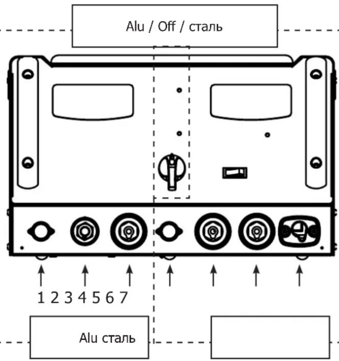
OPERATING AND SETTING (FIG I-II P.2)
SWITCH with 3 positions: Aluminium/OFF/Steel:

New generation dent puller 2 in 1. The GYSPOT Combi 230 E PRO is a dent puller for steel and aluminium car bodies. Cost-effectiveness and time saving is provided by this method of repair by pulling single-point and multi-points without disassembly.
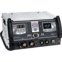
This device contains 2 dent-pullers with two control panels:
| A steel dent puller An aluminium dent puller | |
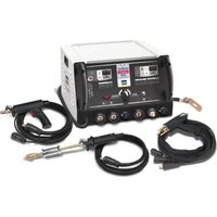
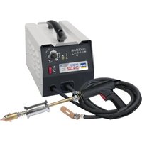
| Generator with multi-function guns and an earth cable. - The gun with trigger connects to terminal no.5; command cable connects to terminal no.4 - The automatic gun (no trigger) connects to terminal no.6 - The earth cable is fixed on position no.7 | Capacitor discharge generator, with one gun equipped with an earth adapter (3 brass terminals) - The gun connects to terminal no.2 - The command cable connects to terminal no.1 - The earth cable connects to terminal no.3 |
A- Steel position (fig. I)
- Connect the machine to an appropriate power supply.
Nb: Combi 230 E Pro has, in addition to the power connector, a connector to command the torch trigger - Connect the latter if you wish to start by using the trigger
- Disconnect it if you prefer use the generator with automatic start (see OPERATION section)
- Press the « on/off » key (6)
- The indicators switch on for few seconds then the machine displays:
- Tool, n^1 by default, (star welding or dent pulling clamp).
- Power level, n^5 by default, (setting adapted for 0.8mm steel sheets).
- To change the power level, press the + or - keys (3). Keep the desired key pressed to scroll through the levels automatically.
- The available power levels allow the straightening of sheets of varying thickness (fig. I-2).
To change the tool used with the gun, press the tool selection key (I-3);
The tool indicator will blink for 5 seconds. During this time, it is possible to change the tool number by pressing the + or - keys (3).
Available tools (fig. I-3)
1 Straightening using the star hammer, or dent pulling clamp
2 Crimped welding wire or rings for straightening.
3 Impact reduction with specific copper tip.
4 Carbon electrode for tempering.
5 Welding rivets for side rods
6 Welding rings for fixing vehicle body.
7 Welding studs for vehicle body and connecting beams
Start-up:
With use of the trigger
The Combi 230 E Pro features 2 start-up settings:
- Manual, by using the trigger (Attach the power and command connectors)
- Automatic, see below. (Attach only the power connector)

In manual mode, connect the power and trigger command cables.
The automatic mode is disabled, only a pressure on the trigger will generate the arc.
The switch allows activating or deactivating the trigger gun.
Without use of the trigger
The machine is able to generate the welding arc automatically.
The generator will automatically detect the electrical contact and generate the welding arc in less than 1 second. To create a new arc, stop the contact with the gun tip for at least 12 second and establish contact again to form another arc.
Operating:
- Proceed as follows:
-
Connect the earth clamp of the generator to the sheet metal to be straightened and follow the instructions below:
-
la placer au point le plus proche de l'endetroit où vous devez travailler.
-
ne pas la connecter sur une piece voisine (ex: ne pas connecter la masse sur une portiere pour redresser l'aile)
-
décaper proprement la tôle à l'endetroit de la connexion.
-
Grind the area where the metal is to be worked.
- Attach the required tool to the end of the gun, tightening the nut firmly
- Select the tool and the power level (see "Operating and Setting") on the machine)
- Make contact between the tool on the gun and the metal.
- Generate your welding arc.
Caution: For optimum operation, it is recommended to use the delivered earth cable and gun originally supplied!
B- Position Alu (fig.II)
The COMBI 230 E PRO was designed to carry out repairs to aluminium car bodies, which have minor dings and dents, marks, scratches or hail damages.
Short charging times and thus quick welding sequences are accomplished.
The robust construction ensures high reliability and high power-on time.
The COMBI 230 E PRO welds M4 studs using capacitor discharge technology.
The welding is very fast (2 to 3 milliseconds).
The COMBI 230 E PRO has 2 operating modes:
Voltage programming mode: from 50 to 200 Volt.
Power programming mode: L,1-9,H. L means low, H means high:
- Switching from voltage mode to power mode is done by pressing the key (1) (Cf. Fig II-1). See table Power vs Voltage (Cf. Fig. II-2).
- Press the on/off switch (2) on the right of the keyboard (Cf. Fig. II-1).
-
Notice: the earth adapter is factory mounted
-
Grind the area which needs to be straightened, such that the 3 brass pads can make the ground contact with the aluminium car body.
- Position the stud in the copper tip of the gun. Adjust if necessary the screw adjustment of bumper stud (see pictures below)
- In order to get a good welding of the stud, the base must come out by approximately 1mm from the extremity of the mandrel (6)
- The position of the stud in the mandrel can be adjusted by screwing / unscrewing the nut on the adjustment screw (4)
Upon delivery of the gun, the screw (7) is loosened and the cursor (8) is in abutment. This setting allows exerting a force of about 20N during welding, which is suitable for welding aluminium studs M4. The screw is used to adjust the down force of the spring when the shot is fired or to compensate for the wear of the spring.
Adjust the power or the voltage value using + and - buttons. At power up the power value by default is 5 which is 100 volts. In general, the value to have a good welding of a M4 stud for small dent removal is: voltage = 90 V or power = 4.
Increase the voltage for thicker panels. Be careful, too elevated power can damage the copper base.
For a good weld, only the « nipple of the stud » must be in contact with the component.
Make a small pressure on the gun without crushing the "pin" of the stud. The capacitor discharge is done automatically when the support comes in the ring.
At this moment the stud is correctly welded. Welding duration is less than 3 milliseconds.
For an optimum repair, we advise you to warm up the metal sheet.
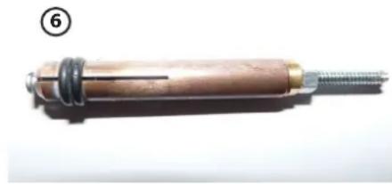
The copper base has 4 slots and is dedicated to M4 studs
(4)


Automatic gun without trigger
Screw for adjusting the stud's position.
The pin must be perpendicular to the sheet.
Do not press too much to not overwrite the nipple. Only the stud is in contact with the sheet.
The base must come out by approximately 1mm from the extremity of the mandrel.
⑦ A wheel with index ⑧ allows adjusting the compression of the spring.
THERMAL PROTECTION
The machine is provided with an automatic thermal protection system, which will stop the machine to prevent it from overheating. When the Thermal Protection Indicator illuminates (fig.I-5 - II-5), let the machine cool down.
WARRANTY
The warranty covers faulty workmanship for 2 years from the date of purchase (parts and labour).
The warranty does not cover:
- Transit damage.
Normal wear of parts (eg.: cables, clamps, etc.). - Damages due to misuse (power supply error, dropping of equipment, disassembling).
- Environment related failures (pollution, rust, dust).
In case of failure, return the unit to your distributor together with:
- The proof of purchase (receipt etc ...)
- A description of the fault reported
NORM
ALLGEMEIN

I3MeHeHn I pEmoHT, He yKa3aHHbE B 3ToI INHCTpyKcUN, He DOJXhbl 6bITb npeDnpHnTbI.
Pon3BODNTeH He HecET OTBeTCTBeHHOCTn 3a TpaMbI N MaTePnaJIbHbIe NOBpeKdEHN CBr3aHHbIe C HECOTBeTCTBYIOUM DaHHOH INCHpyKcIMN HcNoJIb3OBaHHem annapata.
B cnlyae npo6nembl nll comhenn, 06paTntcB K KBaIIINΦIuPobAHOMy CneuaJIACTy IJRA npaBnHOrO INCNOJb3OBaHMy yCTaHOB
HaHHbIe HNCTpyKun KacaiotcB O6pydoBaHn B TOM COCToHn, B KOtOpem erO doCTaBn. Nolb3oBaTeNb DoJKeH npOBecn anAin3 pncOB B clyae Heco6nOHeHn daHHbx INCHtpKun.
OKPYKAIOLUAR CPEDA
3To 06OpdyoBaHHe DoJHKHO 6bTb NcNoIb3OBAHO NCKIIOHTeBHO Dnla CBapOHybIX pa6Ot, orpaHHuBaBC yka3aHmN 3aBOckOy Ta6IuKn H/IN INCTpyKcH. Heo6xOIMO CO6JIIODaT bIpeKTNBbl No Mepam 6e3OnacHocTn. B cnyae HeHaJNeKaUero nn OnaCHOr NOcNoIb3OBAHn IpON3BOIDTeJIb He Hecet OTBETCTBEHNOCTn.
AnnapaTdoJIkeH6bIbYcTaHOBJIeN B NOMeUeHH 6e3 nbIIN, KcNcIbI, Bo3rOpaeMbIX ra3OB, ININ dpyRnx KoppO3nHbIX BeueCTB.
Takne je ycnoBna doJXHbI 6bITb co6nOeHbI dner erO xpaHeHHa. Y6eNTecB B npncyTCTBn BeHTNJaCn npn nCIONb3oBaHN annapata.
Temnepa typbIe npedeJIbI:
IcnoIb3ObaHHe:OT-10do +40^ (ot +14 do +104^
XpaHHeH: oT -20 do +55°C (oT -4 do 131°F).
BnaxHoCTb BO3dyxa:
50% nii Hnke npn 40^ (104°F).
90% nii hnxepn 20^ (68^)
BbICota HauypOBHem Mopr:
1000MBbICOtBHaHypOBHemMopr(3280yTOB).
INHINBNUDAJbHA3AUNTA IN 3AUNTA OKPYKAIOUX
KoHTaKTHaBcBapKa MoKet 6bItb OnaCHO n Bb3BaTb TReXeIbIe I daXe CmePeJIbHbIe paHeHn. BApNTb KOtAKTHO CBAPKO MOryT ToJbKO KBaIIINΦuINPOBaHHbIe CneuaJIInCTbl, CneuaJIbHO oBuYeHHbIe Ira Pa60TbI c DaHHbIM annapaTOM (HaNPmEp: cIecapb no KY3OBHOMy peMOHTy).
Cbapouhhe pa60tI noBepraOT nOJIb3OBaTeJr BO3dEICTBnO onaCHOro nCTOuHnKa TeNla, NCKp, 3NeKTPomarHnTHbIX nOJe (OCO6oe BHMaHHe IucaM, IMeIOUm 3NeKTPOKApDIOCTUMyTIpO), CINbHOMy UMy, BbldeHnM r3a, a TAOKe MOrYT CTaTb npuHHoN IopaxHeH 3NeKTPnueckm TOKOM.
YTo 6bl npabInbHo 3aunTntb ce6n 3aunTntb okpykaioux, co6nlaTe cneyioune npabina 6e0nacnoctn:

YTo6b3aunnttbc68OTOKOBnO6nyehn npn pa6ote c annapatom,HaedeBaTe cyxupa6oyu 3aunthy0 odexdy (B xopoem coctoHH) n3 orHeynopHOn TkaHN,6e 3OBOPoTob, KOtopa NOKpbBAet NnHOCTbIO BCE TeNo.

NcnoB3yIe cpeCTBa 3aunTbI dIy CBAPKn n/nn nnem IyCBAPKn COOTBeTCTByIOero ypOBHra 3aunTbI (B 3aBNCMOCTn OT NcnoB3OBAHH). 3aunTte rla3a npn onepaunx OCHCTKn. HoWeHne KOHTaKTbIX JINH3 Bocnpueaetca.

B HeKoTOpbix Cnyaax Heo6xOdmo Okpykntb 30Hy orHeynopbIMn 7TopamN, YTo6bl 3aunNTb 30Hy CBAPKn OT 6pbI3n HakaenHoro 7naka.
Ppeynpeinte liu, haxoJxncsB 30He CBapKn, YTO OHn DOJIKNbI HOCNTb 3aunTHyIO paOuyIO odexky.
Hocnte HayuHnKn npOTnB yMa, cInn CBAPoHbI npOceC DoCTnraE T3ByKOBOrO yPOBHe Bblue D03BOJeHHoro (3TO JKE OTHOCITcK KO BCem IINaM, HAXODJIUMcB 3OHe CBapKn).

HnKOrda He ChmMaIte 3aunTHbIK Kopnyc C cnCTeMbIOxJaXdeHnRA, KOrda nCTOuHnK nOd HapJKeHnEM. POn3BODInTeJI He Hecet OTBeTCTBeHHoCTN B Clyae He cHcAocTHoro Clya.
ToIbKO yTO cBaPeHHbIe DeTALn IopAyn N MOrY Bb3BaTb OXoRn PnP KOHTaKTe C HmN. Bo BpEm TExO6cIyKuBaHn Kneuei nn nCTOnTe Ta y6eInTeCb, yTO OHn DoCTaTOUHO OxJaIMnCb N NOOXnTe KaK MNHMym 10 MmHyT nepeh NaJom pa6OT. PnN cNoB3OBaHnn Kneuei C XnIDKoCThBIM OxJaXDeHHeM CNCTema OxJaXKeHn DOJIxHa 6blb BKJIOUeHa, YTO6bI He 06xeYBCsra XnIDKoCTbIO.
OeHbaxho 063onacntb pa6ooyu 3ohy nepeTem, kae ee NOKHyTb, TTo6bl 3aunNTb IHOe n IMyueCTBO.
CBAPOHbIEDbIMIgA3
BbIeBmIe np CBapKe DbIM, ra3 n PbIb onaChbl Iyra 3doOpBB. BeHTnJIaCnI DOJXHa 6bIT DoCTaTOHOr, mOxet NoTpe6oBaTcBdONOHInTeBHa NaDaa B03dyxa. PpN HeIOCTaTOUHO BHTnJIaCn MOxHO BOCNOJb3OBaTbcMacko CBAPuKa-pecnnpaTopOM.
PpOBepTe, yTO6bI BCacbIBaHHe BO3dyXa 6blIO 0ΦΦeKTHBbIM B COOTBeTCTBn C HopMaMn 6e3ONaCHOCTn.
BbTe BnMaTeNbHbI: CBapKa B He6oJbXnx NomeeHnX Tpe6yEt Ha6JIIOeHnHa 6e3OaChom pacCToHn. Kpme TOrO, CbapKa HekOTopbIX MeTaNIOB, CoepKaaXnx CbHneU, KaDMn, UINK, pTyTB IIN daKe 6epnnn, MoKet 6bITb Ype3BbuaHNO BpeHO.
OuHCTnTe OT Jknpa DeTAnI nepei CBapko. Hn B Koem Cnyuae He Bapntb B6n3n Jknpa nn KpaKn.
PNUCKIIOXKAPA N B3PbIBA
Iohctbho 3aunntte 30hy cbapkn. Bo3ropaeMbI MaepnJIb IOnKhbI 6bITb ydaJeHb Ka K MHNMym Ha 11 MetpoB. IpOtnBOONOKapHOe o6OpydoBaHne doJIKHO hXoDHTCB R B5nnI npOBeDEHn CBAPOHbIX pa6OT.
Bepenntecb6pblrnpraero MATEPnna HNN NCKP, T.K. OHN MOYr Bb3BaTb NOKAP NNN B3pbVB daKe uepe3 uenn.
YdaIInTe IIOe, Bo3rOpaembIe IpeMToBn BCE mKoCTn IOd daBHeHmHa 6e3OnaCHOe paCToHHe.
Hn B Koem Cnyaee He Bapnte B KOHTeiHepax IIN 3akpbItbIX Tpy6ax. B cnyae, eCNI OHN OTKpbIbTI, To nped cbapko INx Hx HxHOOCBO6OAnTb OT BCEX B3pbIbUaTbIX IIN BO3rOpaEmbIX BeueCTB (MacNO, TOJINBO, OCTaTOHbIe ra3bl ...).
Bo Bpemr Oepaunn IInIphOBAHn He HnPaBnTe INHCTpyMeHT B CTOpOHy NCTOChNk CBapOCHOro TOKa IIN Bo3ropaEmbIX MaTePnaIOB.
3JIeKTPnueCKA B3OnACHOCTb
NcnoB3yemra 3neKtpueckra cetb doJxHa 06a3eIbHo 6bITb 3a3eMHeHNo. 3neKtpueckn pa3pnd MoKeT Bbl3BaTb npMbIe Nnn KocBeHHbIe paHeHn, n daXe CmepTb.
HnkOrda He doTpaRnBaIteB do quchTe noHnapJxHeHem KaK BHyTpN, TAK n ChapyKu NCTOCHka (Ka6eJI, 3JeKtpoDbI, PNeuN, nCToJeT...), T.K. OHN noKnIOUChEbl K CBAPouHOn ceHn.
Ipeed Tem, KaK OTKpbITb NCTOCHNK, ero HyxHO OTKJIIOHTb OT CETN I NOOXdTaB 2 MNHyTb I JRA TORO, YTO6bl BCE KOHDeHCATOpby pa3pndnncb.
Ecnn Ka6en, 3neKtpoDbI nn nnn neyn nobpekdeHbI, nonpocnte KbaHnHnnpoBaHHbx I ynoHMOueHHbx CneuaNCTOB IN 3aMeHNtB. Pa3mepbl cehenra Ka6eJe IOnKhbl COOTBeTCTBOBaTB npimeHeHHIO. Bcerda Hocnte cyxyIO odekY B xopoWeM CoCTOHN II na 130JauuON OT CBAPouHoi cenH. Hocnte n3onpyuoyuO obyBb He3abncmo OTo TOn cpebl, rIe Bbl pa6otaete.
KJIACCHNOKAUHRAJ3JEKTPOMAHHTHOJ COBMECTMOCTH
3To 60bHnne KnaC A He NdoXoDnT nncNoB3OaHn B Xnblx KBapTaJax, rde 3eKtpueckn ToK npdaetc 6oecBeHHo CNTeMoN nntAHn Hn3koro HnnpjKeHn. B Taknx KBapTaJax MOyT Bo3HNKHyTb TpydHocn 6oeceHn EkeTpomarHHTHyIO COBMeCTUMOCb I3-3a KOHdyKTNBblx INHdyKTNBbIX NOMex Ha padnoactoTe.
3TOT annapat He COOTBETCTBYET DnpeKtne CEI 61000-3-12 n npedHa3Hauen dny pa6oTbO T acThbIX 3NeKtpoceteN, NOBedeHHbx K O bueCTBeHHbIM 3NeKtpocetm TObKO CpeHero N BbICOKO HapJKeHry. CneuaJIncT, YcTaHOBBWn annapat, INN NOB3OBaTeNb, DOJXbI y6eDITbcR, OpaTuBwUncB npn HaDo6HoCTN K oprAHn3aun, OTBeuAIOSe 3a EKnIyatauio CNTEmbl NITaHry, B TOM, YTO OH MOxET K HEN NOKIIouHTbcR.
MAGHNTbIe NOJIa
3NeKtpnueckm TOK, npoxoJusn chpe3 IIO60 npOBdHnK, BbI3bIbaET IOKaIIN3OBAHHbIe 3NeKtpomarHHTHbIe nOJIa (EMF). CbapouhBn TOK Bbl3bIbaET 3NeKtpomarHHTHOe nOJIe BOKpyr CBapOCHN cENN n CBapOCHORO o6OpydoBaHn.
3NeKtpomarHnTHbIe noJI EMF Moryr co3daTb nomex nI HeKOToBix MeINHCKNX IMNJaHTaTOB, HAnpMep 3NeKtpokapdIOCTmMyJATopOB. Mepbl 6e3oNaChOCTn DOJIKNbI 6bITb PnHHaTb IJIPOdei, HOcAIXx MeINCHCKNE IMNJaHTaTbI. HanpIMep, orpaHnueHeNe doCTyna dI pyoxoxnx nn OceHka INDINBuaJbHorO pNCK da CBAPsika.
YTO6bI CBECTN K MHNHMy BO3DeiCTBHe 3JIeKTPOMaHHTbIX IOne CBAPoHbIX cIeNe, CBAPuKN DoJXHbI CJeIOBaT bCJeDyUOIM yKa3AHnM:
CbapouhIe KaBJIIN DOnJXHbI HaxOaNTbCBAMeCTe; eCNN BO3MOxHO CoeDInHInTe INX XOMYTOm;
BaWe TynOBnue I rOIOBA DoJXHbI HAXoINtbcra KaK MoXHO daJIbwe OT CBapOCHou cenn
- He 06MaTbIaHTe CBapOuHbIe KaBcIIN BOKpyr BaUero TeIa;
Bahe Teno He doJHKHO 6bTb paCnoJoxeHo MeKdy CBapOHyIMN Ka6eMa. Oba cbapOHyIX Ka6eIa DoJxHbI 6bTb paCnoJoxeHbI no Ody CTOpOHy OT BaWero TeHa;
3aKpeNITe Ka6eJIb 3a3EmnEHHa CBapNBaEMOJ DeTaN KAK MOXHO 6IHXe C 30He CBAPKN;
- He pa6oTaTe p4dOm, He cnDnTe n He 06IIOKaHbaiTecb Ha NCTOCHNK CBAPoHORO TOka;
He Bapnte, KOrDa Bbl NpeHocnTe IcToUHnK CBapOuHoro TOKa IIn YCTpoCTBO NOaUn PpOBoJOkN.

Iiua, nCnoB3yUoune 3JIeKtpokapDnOCTmUyTOpbI, DOnXHbI npOKOHcyNbTupOBaTbcra y BpaHa nepepa60Toi c daHHbIM o6OpydoBaHnEM.
Bo3dECTBnE 3nKTPomarHHTHO nIa B npouecce cbapkn MoKeT mMeTb NdpyRne, eue He n3BeCThBiE HayKe, nocJeCTBnI DnI 3DopOBbJ.
PEKOMEHDAUINIJL OUEHKN 3OHbICBAPKN CBAPOUHOYCTAHOBKN
06nne noJoxeHHa
Iolb3oBateIb OTBeueaET 3a yCTaHOBky I nCnOlb3oBAHne aannapata KOHTaKTHOH CBAPKn, CneJy Yka3AHmIM npOn3BOHNTeJI. PnO bHaPyrKeHHN 3NeKTPOMarHHTbIX N3lyueHn NOB3oBaTeJI aannapata KOHTaKTHOH CBAPKn DOJXeHn pa3peWntb np6bnemy C nOmoUb ToxHnueckO NoepKKn pOn3BOHNTeJI. B HeKOTOpbIX cLyuayx 3TO KoppeKTHpyHOuee DeJeCTBn MOKeT 6bITb DoCTaTOH npocTbIM, HAnpImep 3aemHeHne CBAPouHoi ceNn. B Dpynx Cnyaax BO3MOxHO notpe6yeTc CO3dAHIe 3NeKTPOMarHHTHOrO 3kpaHa BOKpyr IVToCHnKa CBapOHyoro TOKa I Bce CBAPINBaEMoI DeTAL INyTEM MoHTnpOBAHn BXODhBX fNtPOB. B JIO6OM cNyae 3NeKTPOMarHHTbIe N3lyueHn DOJKNbI 6bITb YMeHbWeHbI TaK, UTO6bl OHn 60JIbWe He Co3daBANI NOMex.
OueHka 30HbICBapKn
Ipepe yctahOBKOObopyoBaHn KOthAKTHO CBAPKn Nolb30BaTeNb DOJKeH OueHHTB Bo3MOXHbE 3NeKtpOMaHHTbIe np6JIeMbI, KOTOpBle MOry BO3HNKHyTB B OKpykaUoJe CpeJe. CneDyIOuJe MOMeHbI DOnJHbI 6bITpNInrTbI BO BHIMAHHe:
a) haJIuHne HaI, nOd IIN PRAOM C o6OpyIDoBaHNEM KOHTaKTHo CBAPKn, dpyrnx KaBeJe NITaHnry, ynpabLeHnry, cnHaIINaun HTelefoHa;
b) npneMHnK n nepeDaTchKn paDnO n TeLeBnDeHn;
c) KOMnbIOTepbI IN dpyrIe yCTpOJCTBa ynpaBJIeHnIa;
d) 60pyoobAHne IJIe 63onacHOCTn, Hapmep, 3aunTApomblHHeHOrO 60pyoBaHn;
e) 3dopOBBe HaxoJxxCs no-6nH3OCTn IIOJe, HApPmEp, nCNoB3yIoXx KApDIOCTMByIaTOpbl N yCTpOJIcTBa O T rIyXOTbI;
f) INHCTpymEnT, INCNoIb3yEmbI dIa KaJIb6pOBKn IIN NIm NImepeHnra;
g) nomexoyctoynBOCTypyrOToOBpyoHaxoJzEroCnNo6JIn3OCTN.
Iolb3oBateJI doJKeH y6eInbC B TOM, YTO BCE annapaTb I NOMEueHn COBmectmbl Dpyr C npyrom. 3To MOKET nOTpe6oBaTb co6HIOEHH JOONHHTeJIbHbIX Mep 3aunTbI:
h) onpeeneHHoe Bpem dH, KOrda CBapka uIN dpyrne pa60tb MoKHO 6yET BbIOnHHTb.
Pa3mepbipaccMaTpmbaEMO30HbCBAPKn3aBnCtOTCTpykTpybI3dAnHnNpyrnxpa6oT,KOTOpbIEBHeIpOBoAra. PaccMaTpnaBaemar 30Ha MoKet npoctnapTa 3a npedeJIb pa3MeueHn yCTaHOBKn.
OueHka CBapouHoi yCTaHOBKn
IOMIMO OueHKN 30HbI, OueHKa annapaTOB KOHTaKTHOH CBAPKMOKET NOMOy ONpeENITb IN peWNTb CNYaH 3JIeKTPomarHHTbIX NOMex. OueHKa n3nyehn IOnkHa yuHTbBaTb N3mepeHn B yCIOBnX 3KcNlyaTaUIN, KaK 3TO yka3aHO B CtaTbe 10 CISPR 11. N3mepeHn B YcIOBnX 3KcNlyaTaUIN MOrYT TaKke N03BOJNTb NOdTBePdNTb 3ΦΦeKTHBHOCTb MEP NO CMrYeHIO BO3deCTBIA.
PEKOMEHDAUINI NO METOADNIKE CHNXEHNIALEKTPOMAHHTHOI N3JNUYEHNIA
a. 06eCTBeHHaCnCTema nHTAHn: annapat KOtAKTHoCbapKn HxKHO NODKIOUChTb K oOSeCTBeHHo CTeN nHTAHn, cIeYr peKomeHdaIaI m npOn3BODInTeJI. B cnlyae Bo3HKnHOBEHn IOMex BO3MOXHO 6yDet Heo6xoJIMo pINHrTb DOnOIHNTEhBiye npEynpTeJIbHbIe Mebl, taKne kak fHbTPaIauN OoSCTBeHHo CNCTeMbI nHTAHn. Bo3MOXHO 3aIITNb UHyp nHTAHn aIIAPAATA C NOMOsbIO 3kpaHn3IpyUOe eONlETKN, IIN6O NOXKMn PnICNOC6JIeHMe (B cnlyae eCN I annapat KOtAKTHo CBAPKn NOCTOH HHO hAxOHTcRa Ha ONpeJeHHom pa6oem MeCTe). Heo6xoJIMo 06CeNeuTb 3JeKTPnuECKyU HnpepbIBHOCTb 3KpaHn3IpyUoeonlETkn No BcE nnHHe. Heo6xoJIMo NODcoEINHTb 3KpaHn3IPUOUIO ONlETKY K INTOCHNky CBAPouHOrTo Toka dIra ObecneueHn XopoWero 3JeKTPnuECKoro KOtAKTa MExdy uHypom i Kopnycom NCTOCHNka CBAPouHOrTo Toka.
b. Texo6cnykBaHne annapata KOHTAkhO CBAPKn: annapat KOHTAkhO CBAPKn HxKHO Heo6xoDmO nepnoDnueckn 06cnykBaTb corlacho peKomeHdaunm npOn3BODnteJI. Heo6xoDmO, yTo6bl BCE DoCTynbl, IIOKN oOTKnDbIAuOuNecra cactn Kopnyca 6blI 3aKpbItbl nPaBnblHo 3akpenIeHbl, KOrda annapat KOHTAkhO CBAPKn roTOB K pa6ote nn HaxOJTcB pa6ooyem CoCToHnn. Heo6xoDmO, yTo6bl annapat KOHTAkhO CBAPKn He 6blI nepeJeaH kAkIm 6bl To Hn 6blIO o6pa3OM, 3a NCKLIOUHeHem HaCTpoek, Yka3aHHbIX B pyKOBOdCTBe npOn3BODnteJI.
c. CbapoHbIe Ka6eJI : Ka6eJI NdoJXHbI 6bITb KaK MoXHO KopoYe I nomEueHbI npyr praOM c dpYROM B6n3N OT nOla nn Ha noJy.
d. 3KBHnToEHnauhBle coeHHeH: Heo6xOIMo o6ecneHTb coeHNHeHne Bcex MetaJIInuecknx npedmetOB OkpykaIOuee 30Hb. TeM He MeHee, MetaJIInueckne npedMetbI, coeHNHeHHbIe CO CBAPINBaEM OTeAJIbO, yBeINuHBaOT pNCK dIra IOnb3OBaTeIy UdaP a 3JIeKTPnueckm TOkOM, eCNI OH OndHOBpeMeHHO KOCHTc 3Tnx MetaJIInuecknx npedmetOB n 3JIeKTPoJa. OnpaTOp dONJKeH 6bItb N3OJIinpobAH OH TAKNX MetaJIInuecknx npedmetOB.
e. 3aemnne Cbapnaemoi Detan: B cnuyae, ecn cbapnbmae Jetanb He 3aemnha no coo6paxenm 3JeKtpuecko 6e0nacnoctn nB Cnly CBOx pa3mepo n CBOero paoNoKeHnA, KaK, HApnpMep, BCnyae Kopnyca CyHa nIIM MeTAnIOKOHCTpyKun npomblneHHoro o6bekta, To coeHNHe ne Detan C 3emNe, MoKET B He KcOTOpbix CnyaRax, Ho He CNTMaTHeCKn, COkpaTtB bIbpcobI. Heo6xoDMIO n36eraTb 3aemnne DeTaJIe, KOToPbIE MOrIn 6bl yBeINHTb Ira NlB3OBAteJe PnCKn paHeHn IIN Je NOBpeDnTb Dpytne 3NEKTPooyCTahOBKn. Pn HAdo6HoCTn, CledyET HAprrMyIO nOcEOHNITb DeTaN B 3eMIIe, HO B HeKOToPbIX cTpaHax, KOToPbIE He pa3peWAIOT npJMOe NOcEOHNHeHne, erO HyXHO CDeNaTc NOMOuBo IONxDoxaIero KOHDeHCaTopa, Bbl6paHHoro B 3aBNCMOCTOn OT 3aKHOdaTeNbCTBa CTpaHbl.
f. 3aunTa n 3kpaHn3npUo7a onlTeKa: Bb6bpOuHaN 3aunTa n 3kpaHn3npUo7a onlTeKa dpynx Ka6eNe i O6OpydoBaHna, HaxoJaXxCB B 6nI3JExkaUem pa6o7em yactke, NOMoKet ORpAHuHTb np6bnb, CBraHHbIe C NOMexAmN. 3aunTa BCECBapOchHO 30Hb MoKET paccMaTpNbBaTcB R HEKOToPbIX OC6bIX cnyaRx.
TPAHCIOPTNPOBKA IN TPAH3NT NCTOCHNKA CBAPOHORO TOKAK

IcTuHnK CBapOuHoro ToKa OChaueH BepxHe pyKoN IJIpeHocKn/peMeueHn BpyHyIO. BybTe OCTopoXhbl, TTo6bI He HeDOooeHNb erO Bec.Pyka pemHa He CHTaetc STpONOBouHbIM YCTPOINCTBOM.
He noIb3yItecKa6eIIMnIINI nepeMeueHnNIOCTOCHNkCBAPOOHOro TOKa.
He nepeHocuTb NcToUHk Toka HaJ IIODbMn IIn npEmdTaMn.
YCTAHOBKA OBOPUOBAHNA
-06cnebte doctatoHyIO IIOUaIb IINBEHTnIaIcN NCTOuyHnKa CBAPoHOrTo K OprAHaM ynpabHeHn.
-He nCnoB3yIe B cpeDe C TokonpoBoJaueM MeTaNHueCKoN PbInbIO.
CINIOBbIe, ydHnHtEnbHbIe nCBaOpOHbIe Ka6eIIN DoJXHbI 6bITb NOnHOCTbIO pa3MOtaHb BO n36exaHne nepepeBa.

Ipon3bOndTeH He Hecet OTBETCTBeHHoCTn 3a yuep6, HaneceHHb IIOJMy n npedMeTAM B pe3yIbTaTe HnpabNbHorO n onachoro nCNoJIb3OBAHn DaHHoro o6OpydoBaHn.
OBCLYXINBAHNE / COBETbl


Bapntb KOHTaKTHoCbpKO MOryT ToIbKO KbaIINHnIupOBaHHbe CneuaNtcb, CneuaNtbo6yHeHbIe npa60tbc DaHHbIM annapaTOM cTeM, YTO6bI NCIOJIb3OBA Tb BCE erO BO3MOXHOCTn IN pOn3BOJNb CBapOHb pa60tbc corlaCHO npabnnam HOpMaM (HaNPmep: cncapb NO Ky3OBHomy peMOHTy).
- Ipeed Tem, kak npnctynntb K peMOHTy aBtOMo6nIa, npOBepTe, yTO aBtONpOu3BOUInTeIb Odo6pReT nCNoIb3yEmb MeToD CBapKn.
- Texo6cnykBaHnne n peMOHT nCTOCHNka MOryT npOn3BOuNTbc TOnbKO npOn3BOuNTeJeM. JIO6a onepaunna HAD nCTOCHNKOM, COBepweHHa NOCTOPOHnM IInC0m, ABToMaTuYeCKn OTMeHReT rapaHTnIO. IpOn3BOUNTeJIb CHImaET C Ce6a BCaKyIO OTBeTCTBeHHOCt b 3a HeCuaCThIe CnyuAn, npOnCSeUWe BCNeDCTBnE 3TOI DeICTBnI.
- OTKIIOHTe NITAHHe, BbIepHyB BUNKy I3 po3ETKn, IN DOxNITcB OCTaHOBKn BEHTINrTopa nepeD TeM, KaK npNCtynTb K Texo6CnyKnBaHnIO. BHyTp n annapata BbICOKne n onacbte HnpanjKeHne n TOK.
- Ipeed nCnoB3oBAHnEM nHCTOJeta npOBepaTc coCTOHaHE pa3NHybIX akCEccyapOB (3Be3DOUka, 3JeKTPoD dIra ODHOCTOHHe CBAPKn, yToHbN 3JeKTPoD nT.D.), OUnuaiTe IN NIN 3ameHnTe, ecn OH B PINOXOM COCTOHN.
- PerylaHPO OTKpbBaIte annapat n npodyBaIte ero, YTO6bI OHCTNtB OT nbJIN. Heo6xOIMo TAKKe npOBepaTb BCE 3JIeKTPnueckne CoEINHeHnC NOMOuIO I3OJInpOBaHHOrO INCTpyMeHTa. IpOBepKa DoJIxHa OcyueCTBIArTBc KBAIIHfUncpOBaHHBM CNEuaJIHCTOM.
- Perylaepno npobepnTe coctoHne uHpya nHTAHnI pykaba cbapouHoi cenII. EcnI Ha 3Tnx DeTajx BnHbI NobpeKdHnI, To OHN DOJXhbl 6bITb 3aMeHeHbI npOn3BOIDTeJIeM, erO cepBnCHoi CnyK60I IIN KBaJIuΦnIpOBaHHbIM CNEuaJIncTOM BO N36EkaHne ONaCHOCTNI.
- OctablaIe OTBepCTNn IcTOUHnKa CBAPoHOrO TOKa CBO6OHNbIMn IIN pPOXQKeHnB O3Dyxa.
NODKJIIOUOHENE K CETN
DaHHe o6OpyDoBaHne noCTabJIeTcB C BnKo TnA CEE7/7 Ha 16 A n DoJHKHO NcNoJb3OBAtbc TOnbKO B OndHoa3Hoi TpexnpOBoHDn 3JeKtpocetn 230 B (50-60 Tc) c HeItpaIbHbIM npOBODnKOM, CoeINHeHHbIM C 3emNe. PocToHbN I norIoUeHHbI ToK (I1p), yKa3aHHbI B pa3dene «3JeKtpuYeCKne XapakTepcntKn» DaHHoro pyKOBoDCTBa, COOTBeTCTByET MaKcImaJIbHbIM YcIOBnM EKcPnlyatauIN. Y6eInTeCb, YTO nCTOHTNK nITAHn I erO 3aunTA (npedoxpaHHTeN n/nn aBtOMaTNUeCKN BbIKNIOaTeJIb) COBMecTmblC TOKOM, Heo6XoDMbIM dJa INcNoJIb3OBAHn. B HeKoTopbIX CTpaHax MoKeT Notpe6oBaTcR 3aMeHa BnIK, YTO6bl pa3peWNTb NcNoJIb3OBAHnE B MaKcImaJIbHbIX YcIOBnIX.
NB: Ecn npn BkIueHn B cetb annapata cpa6aTbIbAe 3aunTa cetn, npOBepbTe KaJIbP n TIN nppepbIbATEJ nn npedeoxpAHnteJ.
-
3TN annapatbl OTHocTcK KLnaccy A. OHN co3daHbI DnI NCNoB3OBAHnB B npOMblJeHHo N npOpeccnoHaBHO CpeDe. B IIO60I dpyroI cpeE emy 6ydet CLOXHO oecneHTb 3JIeKTPomarHHTHyIO COBMCTMOCtB n3-3a KOHDyKTNBhIX INHdyKTNBhIX nomex. He NCNoB3OBAbTB CpeDe coedePkaue MeTaANNueCKYIO nbIb-NpOBODNK.
-
Haunna c 1 Deka6pa 2010, Immehenn HOpMb EN 60974-10 6dyt npimeHbC : BHMaHne! 3To o6opyoBaHne He cootBeTCTByET CEI 61000-3-12. AnnapaTb IOnxHb 6bItb NOKIOueHb K O6eCTBeHHo CnCTeMe nITAHn HN3KOrO HAnpJKeHn, NOJIb3OBaTeNb DOJKeH yOCTOBepHTcR, YTO annapaT MoKeT 6bItb NOKIOueH B CeTb. PIn Heo6XoDMocTn pOKOHcyIbTnpyItec b Yaawero 3HeprocnctemHoro onepaTopa.
Mcnoj30BaHne nctOHHka IJIaIOMHHN: B annapate cpa6aTbIbaeT 3aunTa, ecn HapJKeHne nHTaHn IpeBbIaet 265B. Annapat npenrTCTBye TApAky KOHdEHCATOpOB. 3 rOpN3oHTaNbHbIX ceMeHTa B cHTpe dncnner 3aRopaiOTcY, yKa3bIBaHa npCcyTCTBne 3TOrHO HApUWeHn, n RopT, noka deΦeKT He yCTpAHen.
3apKoHcTopoB:Mirahne dinCnpe yKa3bIaet YTO COMBI 230 E PRO 3apXaET KOHeHcTopbI do 3aDaHHoB BEnuHbI. Pnp HApUeHNn 3apJa KOHeHcTopoB nOABTcra CO6UeHne « DEF ». BbIKIOHTe n CHOba BKIOHTe aannapat. Ecnn CO6UeHne nO8BIAETcra ChOBa, CBJKNTEcb c cepBNCHO cnjXbOk OMpaHn GYS.
3ANYCK ANIAPATA N HACTPOIKN (PNC I-II-CTP 2)
AnnapaT nMeet 3-No3nUOnHbI KOMMyTaTOP :
AJIOMHHN/ OFF (BbIK) / CtaIb
AnnapaT I npabkn Ky3Oba HOBORo NOKOEHN 2 B 1. Gyspot Combi E 230 Pro no3BolnE TnpaBnTb cTaNHbIe n aIOMHHBeBle Ky3Obbl. PeHTabNtBHOCTb N BbInrPbIb BpemeHn oEscneuBaETc8 6laorapr TexHOJornn peMOHTa BbITraIBaHMe, C NOMOsbIO ONDOTOHOrO INI MmblTN-ToeUHOro npuBPVAHn 6e3 ChrTna DeTaII.
Annapat coontn 2 annapaTob n npabKc c 2 naheJMy ynpabJIeHna:
| Annapat对于我们npabkn cstani Annapat对于我们npabkn aIIOHMNHIA |
| СИСТОУНКOM, MYЛБТИФУнКЦЮHAЛьнБIMпИСТОЛЕТAMNи Кабелм масьl. -ПисOTETс КеркOM поКлюаeТСК кOHнEkTOpу n°5 иero Кабел yypaBlenHЯ K KOHнEkTOpу n°4. -ПисOTETбЗ Керka поКлюаeТСК кOHнEkTOpу n°6 -Кабел масьl поКлюаeТСК кOHнEkTOpу n°7 |