Gyspot ALU 66 - Generator GYS - Free user manual and instructions
Find the device manual for free Gyspot ALU 66 GYS in PDF.
| Product type | Capacitive discharge welding generator for aluminum dent removal |
| Brand | GYS |
| Model | Gyspot ALU 66 |
| Power supply | Single phase 185-265 V, 50-60 Hz, CEE7/7 16 A plug |
| Continuous power (100%) | 0.52 kVA |
| Secondary continuous current | 4.4 A |
| Max secondary short-circuit current | 13,000 A |
| No-load voltage | 50 - 200 V adjustable |
| Capacitor capacity | 66 mF |
| Supported stud types | M4 and M6 in aluminum (AlMg3 or AlSi12) |
| Main functions | Capacitive discharge stud welding, voltage adjustment (50-200 V) or power (L, 1-9, H), integrated point counter |
| Thermal protection | Yes, automatic shutdown in case of overheating (yellow LED) |
| Operating temperature | -10 °C to +40 °C |
| Storage temperature | -20 °C to +55 °C |
| Permissible humidity | ≤ 50% at 40 °C, ≤ 90% at 20 °C |
| Maximum altitude | 1000 m |
| EMC class | Class A (professional use, non-residential) |
| Protection rating | IP21 |
| Warranty | 2 years (parts and labor) |
| Routine maintenance | Regular dusting with compressed air, checking cables and connections |
| Safety | Detailed instructions: personal protection, fire prevention, management of electromagnetic fields |
| Available spare parts | Cables, gun, copper tips, M4/M6 studs |
| Repairability | Maintenance by the manufacturer or authorized after-sales service; any external intervention voids the warranty |
Frequently Asked Questions - Gyspot ALU 66 GYS
User questions about Gyspot ALU 66 GYS
0 question about this device. Answer the ones you know or ask your own.
Ask a new question about this device
Download the instructions for your Generator in PDF format for free! Find your manual Gyspot ALU 66 - GYS and take your electronic device back in hand. On this page are published all the documents necessary for the use of your device. Gyspot ALU 66 by GYS.
USER MANUAL Gyspot ALU 66 GYS
natural_image
Line drawing of a portable electronic device with ports and wiring (no text or symbols)FR 02 / 03-08 / 57-59
EN 02 / 09-14 / 57-59
DE 02 / 15-20 / 57-59
ES 02 / 21-26 / 57-59
RU 02 / 27-32 / 57-59
NL 02 / 33-38 / 57-59
IT 02 / 39-44 / 57-59
PL 02 / 45-50 / 57-59
CZ 02 / 51-56 / 57-59
GYSPOT ALU 66
I.
text_image
Technical diagram of an electronic device with labeled components and connection pointsII.

text_image
8:00 V ALU DENT PULLER ④ ⑤III.
| P | 2 3 4 5 6 | 7 8 9 H | |||||||||
| V | V 75 V 80 | V 85 V | 90 V 100 | V 108 V | 118 V 12 | 5 V 135 | V 150 V |
AVERTISSEMENTS - RÈGLES DE SÉCURITÉ
CONSIGNE GÉNÉRALE

natural_image
Close-up of a cylindrical mechanical component with threaded end and flange, labeled with numbers 7 and 89 (no text or symbols on the object itself)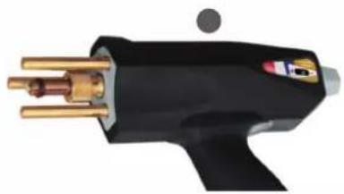
natural_image
Close-up of a black welding torch with gold pins and a small circular mark (no text or symbols visible)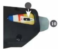
natural_image
Close-up of a handheld electronic device with a colorful internal component and an arrow pointing to a small black button (no text or symbols visible)These instructions must be read and fully understood before use.
Do not carry out any alterations or maintenance work that is not directly specified in this manual.
The manufacturer shall not be liable for any damage to persons or property resulting from use not in accordance with the instructions in this manual.
In the event of problems or uncertainties, please consult a qualified person to handle the installation properly.
The instructions concern the equipment in the condition it was delivered. It is the responsibility of the user to analyse the risks taken when not following the instructions published by GYS.
ENVIRONMENT
This equipment should only be used for welding operations performed within the limits indicated on the information panel and/or in this manual. These safety guidelines must be observed. The manufacturer cannot be held responsible in the event of improper or dangerous use.
The machine must be set up somewhere free from dust, acid, flammable gases or any other corrosive substances. This also applies to storage on the unit. Operate the machine in an open, or well-ventilated area.
Temperature range:
Use between -10 and +40°C (+14 and +104°F).
Store between -20 and +55°C (-4 and 131°F).
Air humidity:
Lower than or equal to 50% at 40°C (104°F).
Lower than or equal to 90% at 20°C (68°F).
Altitude: Up to 1,000 m above sea level (3280 feet).
PROTECTING YOURSELF AND OTHERS
Capacitive discharge equipment can be dangerous and cause serious injury or death. The unit is intended to be operated by qualified personnel who have received appropriate training in the use of the machine (eg: panel beater training).
Welding exposes people to a dangerous source of heat, sparks, electromagnetic fields (caution for those fitted with pacemakers), the risk of electrocution, as well as noise and gaseous fumes.
To protect yourself and others, please observe the following safety instructions:

To protect yourself from burns and radiation, wear insulating, dry and fireproof clothing without lapels. Ensure the clothing is in good condition and that covers the whole body.

Wear protective gloves which provide electrical and thermal insulation.

Use welding protection and/or a welding helmet with a sufficient level of protection (depending on the specific use). Protect your eyes during cleaning procedures. Contact lenses are specifically forbidden.
It may sometimes be necessary to mark off areas with fireproof curtains in order to protect others from splashes, sparks, and arc-eye.
Ask people around the working area to look away from at the arc and molten metal, and to wear protective clothing.

Wear noise protection headphones if the welding process becomes louder than the permissible limit (this is also applicable to anyone else in the welding area).
Newly welded parts are hot and can cause burns when handled.
It is important to secure the working area before leaving it, in order to protect people and property.
WELDING FUMES AND GAS

The fumes, gases and dusts emitted by welding are harmful to health. Sufficient ventilation must be provided and an additional air supply may be required. An air-fed mask could be a solution in situations where there is inadequate ventilation.
Check the extraction system's performance against the relevant safety standards.
Care should be taken when welding in confined spaces, and supervision from a safe distance is essential. In addition, the welding of certain materials containing lead, cadmium, zinc, mercury or beryllium may be particularly harmful.
Remove any grease from workpieces before welding. Welding should not be carried out near grease or paint.
RISK OF FIRES AND EXPLOSIONS

Fully shield the welding area, flammable materials should be kept at least 11 metres away.
Fire fighting equipment should be kept close to wherever the welding activities are being undertaken.
Be careful of spatter and sparks, even through cracks. It can be the source of fire or explosion. Keep people, flammable objects and pressurised containers at a safe distance. Welding in closed containers or tubes is to be avoided. If the containers or tubes are open, they must be emptied of all flammable or explosive materials (oil, fuel, gas residues, etc.).
Grinding work must not be directed towards the source of the welding current or towards any flammable materials.
ELECTRICAL SAFETY

The electrical network used must be earthed. An electric shock can be the source of a serious accident, whether directly or indirectly, or even death.
Never touch live parts either inside or outside of the power source (cables, electrodes, arms, gun, etc.) as these are connected to the welding circuit.
Before opening the welding machine power source, disconnect it from the mains and wait two minutes to ensure that all the capacitors have fully discharged.
Damaged cables and torches must be changed by a qualified and skilled professional. Measure the cable cross-section according to the intended application. Always use dry and in-tact clothing to insulate yourself from the welding circuit. Always wear insulated footwear, in all working environments.
EMC CLASSIFICATION

This Class A device is not intended for use in a residential environment where power is provided by the public low-voltage local supply network. Ensuring electromagnetic compatibility may be difficult at these sites due to conducted, as well as radiated, radio frequency interference.
EN 61000-3-12 This equipment complies with the IEC 61000-3-12 standard.
EN 61000-3-11 This equipment complies with IEC 61000-3-11.
ELECTROMAGNETIC INTERFERENCES
An electric current passing through any conductor produces localised electric and magnetic fields (EMF). The welding current produces an electromagnetic field around the welding circuit and the welding equipment.
Electromagnetic fields (EMFs) can interfere with some medical devices; pacemakers for example. Protective measures must be taken for people with medical implants. For example, restricted access for passers-by or an individual risk assessment for welders.
All welders should use the following procedures to minimise exposure to electromagnetic fields from the welding circuit:
- position the welding cables together - securing them with a clamp if possible;
- position yourself (head and body) as far away from the welding circuit as possible,
- never wrap the welding cables around your body,
- do not position yourself in between the welding cables. Keep both welding cables on the same side of the body;
- connect the return cable to the workpiece, as close as possible to the welding area;
- do not work directly next to, sit, or lean on welding power source;
- do not move the welding power source while it is in use.

Pacemaker users should consult a doctor before using this equipment.
Exposure to electromagnetic fields during welding may have other health effects that are not yet known.
RECOMMENDATIONS FOR ASSESSING THE WELDING AREA AND EQUIPMENT
General Information
The user is responsible for installing and using the capacitive discharge equipment in accordance with the manufacturer's instructions. If electromagnetic interference is detected, it is the responsibility of the user of the capacitive discharge unit to rectify the disturbance by seeking technical assistance from the manufacturer. In some cases, this corrective action may be as simple as earthing the welding circuit. In other cases, it may be necessary to construct an electromagnetic shield around the welding current source, and around the entire workpiece, by setting up input filters. In any case, electromagnetic interference should be reduced until it is no longer an inconvenience.
Welding zone evaluation
Before installing capacitive discharge equipment, the user should assess any potential electromagnetic problems in the surrounding area. The following should be taken into account:
a) the presence of power, control, signal and telephone cables above, below and next to the capacitive discharge unit;
b) radio and television receivers and transmitters;
c) computers and other control equipment;
d) critical safety equipment, e.g. the protection of industrial equipment;
e) the health of nearby persons, e.g. those using pacemakers or hearing aids;
f) equipment used for calibrating or measuring;
g) the sensitivity of other equipment in the surrounding area.
The user must ensure that other equipment installed in the vicinity is compatible. This may require further protective measures;
h) the time of day when welding or other tasks are to be carried out.
The size of the surrounding area to be taken into account will depend on the building's structure and the other activities taking place there. The surrounding area may extend beyond the boundaries of the facility.
Assessment of the welding equipment
In addition to assessing the area, evaluation of the capacitive discharge equipment installation can be used to identify and resolve cases of interference. It is appropriate that the assessment of any emissions should include in situ measurements as specified in Article 10 of CISPR 11. In-situ measurements can also be used to verify the effectiveness of any mitigation measures.
GUIDELINES ON HOW TO REDUCE ELECTROMAGNETIC EMISSIONS
a. The mains power grid: The capacitive discharge unit should be connected to the power supply network in accordance with the manufacturer's recommendations. If any interference occurs, it may be necessary to take additional precautionary measures such as filtering the mains power supply. With capacitive discharge equipment that is being permanently installed, consideration should be given to shielding the power cable in metal ducting or an equivalent. The power cable should be protected along its entire length. The shield should be connected to the welding power source to ensure that there is good electrical contact between the conduit and the welding power source enclosure.
b. Maintenance of capacitive discharge equipment: Capacitive discharge equipment should be subject to routine maintenance in accordance with the manufacturer's recommendations. All accesses, service doors and covers must be closed and properly locked when the capacitive discharge machine is in use. The capacitive discharge unit must not be modified in any way, apart from the modifications and adjustments specified in the manufacturer's instructions.
c. Welding cables: Cables should be as short as possible, placed close together either near or on the ground.
d. Equipotential bonding: Consideration should be given to linking all metal objects in the surrounding area. However, metal objects connected to the workpiece increase the risk of electric shocks to the user if they touch both these metal parts and the electrode. It is necessary to insulate the operator from such metal objects.
e. Earthing the workpiece: In cases where the workpiece being welded is not earthed for electrical safety reasons or because of its size and location (such as the hull of a ship or the structural steelwork of a building for example), an earthed connection can in some instances, but not always, reduce emissions. Care must be taken to avoid earthing parts that could increase the risk of injury to the user or cause damage to other electrical equipment. If necessary, the workpiece's connection should be earthed directly, but in some countries where a direct connection is not allowed, the connection should be made with a suitable capacitor chosen according to national regulations.
f. Protection and shielding: Selective shielding and protection of other cables and equipment in the surrounding area, may limit interference problems. Protection and shielding of the entire welding area may be required for certain specialist applications.
TRANSPORT AND TRANSIT OF THE WELDING POWER SOURCE

The welding power source is fitted with a top handle(s) for carrying / transporting by hand. Be careful not to underestimate its weight. The handle(s) cannot be used for slinging.
Do not use the cables or torch to move the machine.
Do not carry the power source over the heads of people or objects.
EQUIPMENT INSTALLATION
- Provide sufficient space to ventilate the welding power source and access the controls.
- Do not use in an area with conductive metal dust.
- Power, extension, and welding cables must be completely unwound to avoid overheating.

The manufacturer assumes no responsibility for damage to persons or objects caused by improper and dangerous use of this equipment.
MAINTENANCE / RECOMMENDATIONS


- Anyone using this machine needs to have received appropriate training in the use of the device, in order to get the most out of its performance, and to carry out the work in accordance with the instructions (e.g: panel beater training).
-
Check which welding process is authorised by the manufacturer before attempting any vehicle repair.
-
Maintenance and repair of the power source may only be carried out by the manufacturer.
Any work undertaken by a third party on the machine will invalidate the warranty. The manufacturer will not be held responsible for any incident or accident occurring after this work is carried out. - Switch off the power supply by pulling the plug and wait two minutes before working on the equipment..
Inside the macine, the voltages and currents are high and dangerous. - All welding tools suffer deterioration over time. Keep these tools clean to ensure that the machine performs at its best.
- Regularly remove the cover and blow out any dust.
Take this opportunity to have all electrical connections checked with an insulated tool by qualified personnel. - Regularly review the condition of the power cable and welding connection cables.
In case of visible signs of damage, organise for them to be replaced by the manufacturer or a qualified technician. - Keep the air inlet and outlet vents of the welding current source clean and clear.
POWER SUPPLY
- This equipment is supplied with a 16A CEE7/7 plug and must only be used on a single-phase 185 V to 265 V (50 - 60 Hz) three-wire electrical installation with an earth.
- The absorbed continuous current (I1p or ILp) indicated in the "Electrical data" section of this manual refers to the maximum working capacity of the machine. Check that the power supply and its protection (fuse and/or circuit breaker) are compatible with the current required to run the machine. In some countries, it may be necessary to change the plug in order to use it at maximum capacity.
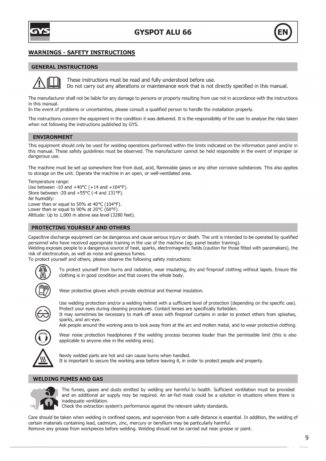
- Starting is done by pressing the I/O switch (Fig. I-3), and stopping is done by pressing the same switch (0). Warning! Never switch off the power supply while the unit is under load.

Capacitor charging: the display flashes to indicate that the GYSPOT ALU is charging the capacitors to the set value. If the capacitors are not charged, the message "DEF" is displayed. Switch the unit off and on again. If the message persists, please contact GYS Aftersales service.
| ELECTRICAL SPECIFICATIONS | |
| Rated supply voltage U1N 1 ~ 185 - 265 V | |
| Frequency 50 - 60 Hz | |
| Rated open circuit voltage U2d 50 - 200 V | |
| Continuous power Sp 0.52 kVA | |
| Continuous supply current I1p 0.7A / 4.5 A | |
| Maximum primary short-circuit current I1cc / ILcc 6.5 A | |
| Maximum secondary short-circuit current I2cc 13000 A | |
| Continuous secondary current I2p 4.4 A | |
| THERMAL SPECIFICATIONS | |
| Ambient operating temperature From +5°C to +40°C | |
| Ambient storage and transport temperature From -25°C to +55°C | |
DESCRIPTION OF THE UNIT (CF. PAGE 2)
This device is used to remove dents from aluminium bodywork by welding M4 & M6 aluminium studs, using capacitor discharge. The capacitors have a rating of 66 millifarads.
Gun cable output (Fig. I-1)
Earth cable output (Fig. I-2)
The front of the device has a keypad with just 3 buttons (Fig. II)
It has a thermal fault LED (Fig. II-5)
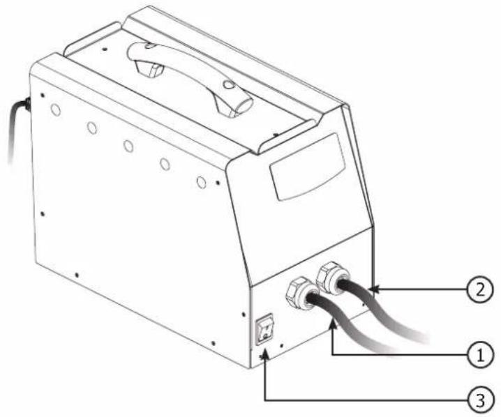
The unit is equipped with a gun that has a 3m interconnection cable.
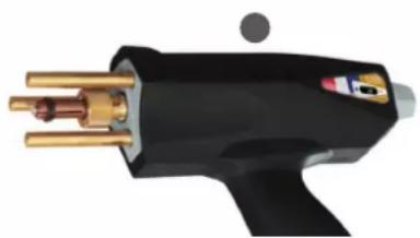
The 3 pins on the gun are used for grounding, and central support for the stud being welded.
M4 and M6 stud types: Alu magnesium (AlMg3) or Alu silicon (AlSi12)
When the unit is switched on, an error message may appear indicating that the trigger on the gun has been held down. It is possible that the button is stuck or has short-circuited. In either case, please contact your distributor.
APPLICATION
This machine has been designed to repair aluminium bodywork with small dents, scratches or hail damage.
This machine welds M4 and M6 studs by means of capacitor discharge. This occurs as soon as the tip of the gun is depressed. The weld is very fast (2 to 3 milliseconds).
This machine can be programmed in two different modes:
- Voltage mode: Voltage is programmable between 50 and 200 V.
- Power mode: Power is programmable between L, 1-9, H:
o To switch from one mode to the other, press the mode button (Fig. II-4)
o Table showing power level and corresponding voltage (Cf. Fig. III).
| P | 2 3 4 5 6 7 8 9 H | |||||||||
| V | V 75 V 80 V 85 V | 90 V 100 | V 108 V | 118 V 125 V 135 | V 150 V |
Description of the Gyspot alu 66 welding process
o Strip the area being repaired in order to ensure that the 3 brass pins can make ground contact with the bodywork.
o Position the stud in the chuck. If necessary, adjust the stud stop adjustment screw (see photos below).
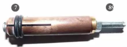
o To ensure a sound weld, the head of the stud should protrude approximately one millimetre from the end cap (7)
o The position of the stud head is adjusted by turning the nut on the adjusting screw (8)
For a good weld, only the "nib" of the stud should be in contact with the workpiece.
Apply light pressure to the gun without crushing the stud, keeping the gun perpendicular to the sheet. The capacitors are discharged automatically as soon as the gun tip is pushed into the ring.
That is when the stud is welded. The duration of the weld is less than 3 milliseconds.
For the best possible straightening performance, we recommend heating the workpiece.
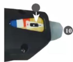
When the gun is first supplied, the adjusting screw 10 is loose and the slider 0 is in the end position. This setting delivers a force of around 20N when the gun is activated, which is suitable for welding M4 and M6 aluminium studs. The screw is used to adjust the force of the spring when the mechanism is triggered, and to compensate for wear.
Set the voltage value using the + and - buttons.
The default power value when the device is switched on is 5, which is equivalent to 100 volts.
In general, the value for a satisfactory weld on a 4 mm diameter stud for dent removal is 90 V. This corresponds to power level 4.
The value of the voltage required increases according to the thickness of the sheet. Caution: excessive voltage can damage the surface.
natural_image
Close-up of a cylindrical mechanical component with threaded end and flange, labeled with numbers 7 and 89 (no text or symbols on the object itself)4-slot copper tip for welding M4 and M6 studs (diameter ∅ 4 mm)
natural_image
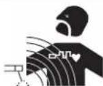
Close-up of a black and gold electric shaver with brass leads (no visible text or symbols)Automatic triggerless gun
natural_image
Close-up of a black plastic electrical plug with a small component inserted, labeled with number 10 (no text or symbols on the plug itself)7 The head of the stud should protrude by about a millimetre.
8 Stud position adjustment screw
9 The stud must be perpendicular to the sheet.
Do not apply too much pressure to avoid crushing the tip. Only the tip is in contact with the sheet metal.
10 A knurled knob with a slider 0 can be used to adjust the amount of compression on the spring when the trigger is activated.
Points counter menu :
A menu automatically counting the number of points completed is available by pressing and holding the Mode button for 3 seconds. The screen will then flash between "CPt" and the number of points completed. By default, when the device is launched, this number is zero. It will be incremented by 1 for each spot welded. To reset the number of points to 0, hold down the "+" and "-" buttons simultaneously for 3 seconds.
When you switch to counter mode, the voltage settings are memorised and will be used for all subsequent stitches. The counter does not reset to zero each time the product is switched off; it remembers the number of stitches made until it is reset manually.
POWER SOURCE THERMAL PROTECTION
This unit is equipped with an automatic thermal protection system. This system stops the power source from operating for a few minutes if it has been used too intensively. In this situation, the yellow indicator (fig. II-5) lights up.
WARRANTY
The warranty covers all defects or manufacturing faults for a period of two years starting from the date of purchase (parts and labour).
The warranty does not cover:
- Any other damage caused during transport.
- The general wear and tear of parts (i.e.: cables, clamps, etc.).
- Incidents caused by misuse (incorrect power supply, dropping or dismantling).
- Environment-related faults (such as pollution, rust and dust).
In the event of a breakdown, please return the item to your distributor, along with:
- a dated proof of purchase (receipt or invoice etc.).
- a note explaining the malfunction.
natural_image
Close-up of a cylindrical mechanical component with threaded end and flange, labeled with numbers 7 and 89 (no text or symbols on the object itself)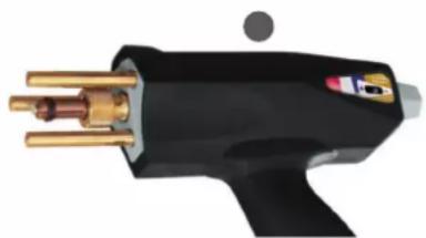
natural_image
Close-up of a black welding torch with brass metal pins and a small circular mark (no text or symbols visible)
natural_image
Close-up of a car interior component with a highlighted orange section and numbered marker (10), no visible text or symbols.WÄRMESCHUTZ DES GENERATORS
natural_image
Close-up of a cylindrical mechanical component with threaded end and metal ring, labeled with numbers 7 and 89 (no text or symbols on the object itself)natural_image
Close-up of a black and gold soldering iron with metal pins (no text or symbols visible)natural_image
Close-up of a handheld device with a colorful internal component and an arrow pointing to it (no visible text or symbols)natural_image
Close-up of a cylindrical mechanical component with threaded end and flange, labeled with numbers 7 and 89 (no text or symbols on the object itself)
natural_image
Close-up of a black and gold electric shaver with brass leads (no visible text or symbols)
natural_image
Close-up of a black electronic device with a small component inserted, labeled with number 10 (no visible text or symbols on the device itself)WAARSCHUWINGEN - VEILIGHEIDSINSTRUCTIES
ALGEMENE INSTRUCTIES

natural_image
Close-up of a cylindrical mechanical component with threaded end and flange, labeled with numbers 7 and 89 (no text or symbols on the object itself)natural_image
Close-up of a black welding torch with gold pins and a small circular mark (no text or symbols visible)natural_image
Close-up of a handheld electronic device with a small component inserted, labeled with number 10 (no visible text or symbols on the device itself)natural_image
Close-up of a cylindrical mechanical component with threaded end and flange, labeled with numbers 7 and 89 (no text or symbols on the object itself)natural_image
Close-up of a black welding torch with brass and gold metal fittings (no visible text or symbols)natural_image
Close-up of a handheld device with a small component and a numbered label (10), no readable text or symbols present.RYZYKO POŻARU I WYBUCHU

natural_image
Close-up of a cylindrical mechanical component with threaded end and flange, labeled with numbers 7 and 89 (no text or symbols on the object itself)natural_image
Close-up of a black and gold soldering iron with metal pins (no visible text or symbols)natural_image
Close-up of a handheld device with a highlighted internal component and an arrow pointing to it (no text or symbols visible)Kabel pistole (Obr. I-1)