Gyspot 2600 - Generator GYS - Free user manual and instructions
Find the device manual for free Gyspot 2600 GYS in PDF.
User questions about Gyspot 2600 GYS
0 question about this device. Answer the ones you know or ask your own.
Ask a new question about this device
Download the instructions for your Generator in PDF format for free! Find your manual Gyspot 2600 - GYS and take your electronic device back in hand. On this page are published all the documents necessary for the use of your device. Gyspot 2600 by GYS.
USER MANUAL Gyspot 2600 GYS
FR 2-9/51-64
EN 2/10-15/51-64
DE 2/16-22/51-64
ES 2/23-29/51-64
RU 2/30-36/51-64
NL 2/37-43/51-64
IT 2/44-50/51-64
GYSPOT 2600
2700
34.02
34.04
39.02
39.04
PRO 230
PRO 400
1
II
III
CC 1
IV
A
B-Gyspot 2600/2700/34.02/34.04
Read and understand the following safety instructions before use.
Any modification or maintenance not specified in the instructions manual should not be undertaken.
The manufacturer is not liable for any injury or damage due to non-compliance with the instructions featured in this manual.
In the event of problems or uncertainties, please consult a qualified person to handle the installation properly.
Make sure to keep the instructions as you might need to refer to them later.
These instructions cover the material in the condition it was delivered. It is the responsibility of the user to carry a risk analysis in case the instructions are not followed.
ENVIRONMENT
This equipment must only be used for welding operations in accordance with the limits indicated on the descriptive panel and/or in the user manual. Safety instructions must be followed. In case of improper or unsafe use, the manufacturer cannot be held liable.
This equipment must be used and stored in a room free from dust, acid, flammable gas or any other corrosive agent. The same rules apply for storage. Operate the machine in an open, or well-ventilated area.
Operating temperature:
Use between -10 and +40^ (+14 and +104^)
Storage between -20 and +55^ (-4 and 131^ ).
Air humidity:
Lower or equal to 50% at 40^ (104^)
Lower or equal to 90% at 20^ (68^)
Altitude:
Up to 1000 meters above sea level (3280 feet).
PROTECTION OF THE INDIVIDUALS
Resistance welding can be dangerous and cause serious injuries or even death. It needs to be used by a qualified technician with training relevant to the machine.
Welding exposes the user to dangerous heat, arc rays, electromagnetic fields, risk of electric shock, noise and gas fumes. People wearing pacemakers are advised to consult a doctor before using the welding machine.
To protect oneself as well as the other, ensure the following safety precautions are taken:

In order to protect you from burns and radiations, wear clothing without turn-up or cuffs. These clothes must be insulating, dry, fireproof, in good condition and cover the whole body.

Wear protective gloves which guarantee electrical and thermal insulation.

Use sufficient welding protective gear for the whole body: hood, gloves, jacket, trousers... (varies depending on the application/operation). Protect the eyes during cleaning operations. Contact lenses are prohibited during use.
It may be necessary to install fireproof welding curtains to protect others against arc rays, weld spatters and sparks. Ask people around the working area to look away from at the arc or the molten metal, and to wear protective clothing.

Ensure ear protection is worn by the operator if the work exceeds the authorised noise limit (the same applies to any person in the welding area).
Parts that have previously been welded will be hot and may cause burns if manipulated. During maintenance work on the torch or the electrode holder, you should make sure it's cold enough and wait at least 10 minutes before any intervention. When using a water-cooled torch, make sure that the cooling unit is switched on to avoid any burns caused by the liquid.
It is important to secure the working area before leaving to ensure the protection of property and the safety of others.
WELDING FUMES AND GAS

Fumes, gas and dust produced during welding are hazardous to health. It is mandatory to ensure adequate ventilation and/or extraction to keep fumes and gas away from the work area. Using an air fed welding helmet is recommended in case of insufficient ventilation in the workplace.
Check that the air supply is effective by referring to the recommended safety regulations.
Precautions must be taken when welding in small areas, and the operator will need supervision from a safe distance. In addition, the welding of certain materials containing lead, cadmium, zinc, mercury or beryllium may be particularly harmful.
Also remove any grease on the metal pieces before welding. Do not weld in areas where grease or paint are stored.
FIRE AND EXPLOSION RISKS

Protect the entire welding area. Flammable materials must be moved to a minimum safe distance of 11 meters.
A fire extinguisher must be readily available near the welding operations.
Keep people, flammable materials/objects and containers that are under pressure at a safe distance.
Welding in closed containers or pipes should be avoided and, if they are opened, they must be emptied of any flammable or explosive material (oil, fuel, gas ...).
Grinding operations should not be carried out close to the power supply or any flammable materials.
ELECTRICAL SAFETY

The electrical mains used must have an earth terminal. An electric shock could cause serious injuries or potentially even deadly accidents.
Never make contact with live parts inside or outside the current source (cables, electrodes, arms, guns...) as they are connected to the welding circuit.
Before opening the device, it is imperative to disconnect it from the mains and wait 2 minutes, so that all the capacitors are discharged.
Damaged cables and torches must be changed by a qualified and skilled professional. Make sure that the cable cross section is adequate with the usage (extensions and welding cables). Always wear dry clothes which are in good condition in order to be isolated from the welding circuit. Wear insulating shoes, regardless of the workplace/environment in which you work in.
EMC CLASSIFICATION

GYSPOT 2600/2700/34.04/ 39.04/PRO400
GYSPOT 34.02/39.02/ PRO 230
This Class A machine is not intended to be used on a residential site where the electric current is supplied by the domestic low-voltage power grid. There may be potential difficulties in ensuring electromagnetic compatibility at these sites, due to conducted interferences as well as radiation.
This equipment complies with IEC 61000-3-11 if the power supply network's impedance at the electrical installation's connection point is inferior to the network's maximum admissible impedance Z_max = 0.77 Ohms.
This equipment complies with IEC 61000-3-11 if the power supply network's impedance at the electrical installation's connection point is inferior to the network's maximum admissible impedance Z_max = 0.84 Ohms.
This equipment does not comply with IEC 61000-3-12 and is intended to be connected to domestic low-voltage systems interfacing with the public supply only at the medium- or high-voltage level. If it is connected to a public low-voltage power grid, the installer or user of the machine has to ensure, by checking with the network operator, that the device can be connected.
ELECTROMAGNETIC INTERFERENCES
The electric currents flowing through a conductor cause electrical and magnetic fields (EMF). The welding current generates an EMF around the welding circuit and the welding equipment.
The EMF electromagnetic fields can interfere with certain medical implants, such as pacemakers. Protection measures must be taken for people having medical implants. For example, access restrictions for passers-by or an individual risk evaluation for the welders.
Each welder must follow the procedures below in order to minimise exposure to electromagnetic generated by the welding circuit:
- position the welding cables together - strap them if possible;
- keep your head and top half of the body as far from the welding circuit as possible;
- never enrol the cables around your body;
- never position your body between the welding cables. Hold both welding cables on the same side of your body;
- connect the earth clamp as close as possible to the area being welded;
- do not work too close to, do not lean and do not sit on the welding machine
- do not weld when you're carrying the welding machine or its wire feeder.

People wearing pacemakers are advised to consult their doctor before using this device.
Exposure to electromagnetic fields while welding may have other health effects which are not yet identified.
RECOMMENDATIONS FOR EVALUATING THE WELDING AREA AND INSTALLATION
Miscellaneous
The user is responsible for the correct installation and usage of the welding material based on the instructions supplied by the manufacturer. If electromagnetic disturbances are detected, it is the user's responsibility to resolve the situation with the manufacturer's
technical assistance. In some cases, this corrective action may be as simple as earthing the welding circuit. In other cases, it may be necessary to construct an electromagnetic shield around the welding power source and around the entire piece by fitting input filters. In all cases, electromagnetic interferences must be reduced until they are no longer inconvenient.
Welding area assessment
Before installing the machine, the user must evaluate the possible electromagnetic problems that may arise in the area where the installation is planned. The following must be taken into account:
a) the presence (above, below and next to the arc welding machine) of other power cables, remote cables and telephone cables;
b) television transmitters and receivers;
c) computers and other hardware;
d) critical safety equipment such as industrial machine protections;
e) the health and safety of the people in the area such as people with pacemakers or hearing aids;
f) calibration and measuring equipment;
g) the isolation of other pieces of equipment which are in the same area.
The user has to ensure that the devices and pieces of equipment used in the same area are compatible with each other. This may require extra precautions;
h) the time of day during the welding or other activities have to be performed.
The surface of the area to be considered around the device depends on the building's structure and other activities that take place there. The area taken into consideration can be larger than the limits of the installations.
Review of the welding installation
Reviewing the welding installations can be useful to determine and resolve any case of electrical disturbances. The assessment of emissions must include in situ measurements as specified in Article 10 of CISPR 11. In situ measurements can also be used to confirm the effectiveness of mitigation measures.
RECOMMANDATIONS SUR LES METHODES DE REDUCTION DES EMISSIONS ELECTROMAGNETIQUES
a. National power grid: The arc welding machine must be connected to the national power grid in accordance with the manufacturer's recommendation. In case of interferences, it may be necessary to take additional precautions such as the filtering of the power supply network. Consideration should be given to shielding the power supply cable in a metal conduit or equivalent of permanently installed arc welding equipment. It is necessary to ensure the electrical continuity of the shielding along its entire length. The shielding should be connected to the welding current's source to ensure good electrical contact between the conduct and the casing of the welding current source.
b. Maintenance of the arc welding equipment: The arc welding machine should be subject to a routine maintenance check according to the recommendations of the manufacturer. All accesses, service doors and covers should be closed and properly locked when the arc welding equipment is on. The arc welding equipment must not be modified in any way, except for the changes and settings outlined in the manufacturer's instructions.
c. Welding cables: Cables must be as short as possible, close to each other and close to the ground, if not on the ground.
d. Equipotential bonding: consideration should be given to bonding all metal objects in the surrounding area. However, metal objects connected to the workpiece increase the risk of electric shock if the operator touches both these metal elements and the electrode. It is necessary to insulate the operator from such metal objects.
e. Earthing of the welded part: When the part is not earthed - due to electrical safety reasons or because of its size and its location (which is the case with ship hulls or metallic building structures), the earthing of the part can, in some cases but not systematically, reduce emissions It is preferable to avoid the earthing of parts that could increase the risk of injury to the users or damage other electrical equipment. If necessary, it is appropriate that the earthing of the part is done directly, but in some countries that do not allow such a direct connection, it is appropriate that the connection is made with a capacitor selected according to national regulations.
f. Protection and shielding: The selective protection and shielding of other cables and devices in the area can reduce perturbation issues. The protection of the entire welding area can be considered for specific situations.
TRANSPORT ET TRANSIT DE LA SOURCE DE COURANT DE SOUDAGE

The welding source is fitted with a handle to make it transportable by hand. Be careful not to underestimate the weight of the machine. The handle are not design to be use to hang the machine to something else.
Do not use the cables or torch to move the machine.
Do not place/carry the unit over people or objects.
EQUIPMENT INSTALLATION
- Provide an adequate area to ventilate the machine and access the controls.
- Do not use in an area with conductive metal dust.
- Power cables, extension leads and welding cables must be fully uncoiled to prevent overheating.

The manufacturer does not accept any liability in relation to damages caused to objects or harm caused to persons as the result of incorrect and/or dangerous use of the machine.
MAINTENANCE / RECOMMENDATIONS


- The operators must have received suitable training in order to use the machine at its maximum potential and weld correctly.
-
Check which welding process is authorised by the manufacturer before attempting any vehicle repair.
-
The maintenance and the repair of the . Any work undertaken by a third party on the generator will invalidate the warranty. The manufacturer will not accept liability in the event of an incident that would occur after this work was undertaken.
- Ensure the machine is unplugged from the mains, and wait for two minutes before carrying out maintenance work. Inside, voltages and currents are high and dangerous.
- All the welding tools will wear off with use. Ensure that these tools are clean to get the best results.
- Prior to using the gun, check the condition of the different tools (star, single sided electrode, carbon electrode...) and clean or replace if required.
- Remove regularly the casing and any excess of dust. Take this opportunity to have the electrical connections checked by a qualified person, with an insulated tool.
- Regularly review the condition of the power cable and welding connection cables. In case of visible signs of damage, organise for them to be replaced by the manufacturer or a qualified technician.
- Ensure the vents of the device are not blocked to allow adequate air circulation.
INSTALLATION - PRODUCT OPERATION
GENERAL DESCRIPTION
This product has been designed to carry out the following operations in a car body workshop: Dent pulling; welding of nails, rivets, rings and pins; removal of bumps and dents; sheet stretching. It is not designed for the assembly of metal parts. This device is delivered with an earth clamp, a gun (with cable), a consumables and accessories box, and an SOOW mains cable.
| Accessories 2600 | 2700 | 34.02 34.04 | 39.02 39.04 | PRO 230 PRO 400 |
| Earth plate | ✓✓✓ | |||
| Separate gun lead | ✓ | ✓ | ||
| Automatic Quick Gun | ✓✓ | |||
| Manual Quick Gun | ✓ | ✓ | ||
| Spotter Box | ✓ | |||
| Spotter Box Pro | ✓ |
PRODUCT SPECIFICATIONS
| 2600 2700 | 34.02 34 | .04 39.02 | 39.04 PRO | 230 PRO 400 | |||
| ELECTRIC SPECIFICATIONS | |||||||
| UNrated power supply voltage | 1 ~ 230 V 2 ~ 400 | V 1 ~ 230 V | 2 ~ 400 V 1 ~ | 230 V 2 ~ 400 | V | ||
| Frequency | 50/60 Hz | ||||||
| U20 rated no load voltage | 5.5 V 7.6 | V 7.8 V De 0.5 | à 7.4 V | ||||
| Permanent power USP | 1 kVA | 1.8 kVA | 2.0 kVA | 1.8 kVA | |||
| Permanent supply current Ip | 4.7 A | 6.9 A | 5.3 A | 7.8 A | 4.7 A | 7.8 A | 4.7 A |
| Maximal current of a permanent primary short circuit I1cc | 43 A | 80 A | 51 A | 90 A | 52 A | 90 A | 52 A |
| Maximal current of a secondary short circuit I2cc | 1800 A | 2400 A | 2600 A | 2800 A | |||
| Permanent secondary current Ip | 160 A | 240 A | 270 A | 270 A | |||
| Type of welding current | ~ | ||||||
| THERMAL SPECIFICATIONS | ||||||
| Operating ambient temperature | De - 10°C à + 40°C | |||||
| Storage and transport operating ambient | De -20°C à +55°C | |||||
| MECHANICAL SPECIFICATIONS | ||||||
| Dimensions (cm) | 20x32x18 | 2.5x36 x23.5 | ||||
| Weight (kg) | 17.8 21 | 22.7 23 25.5 25.5 | ||||
| Protection rating | IP 21 | |||||
ELECTRICITY SUPPLY
- GYSPOT 2600 / 2700 / 34.02 / 39.02 / Pro 230 : The material is supplied with a 16A plug type CEE7/7 and must only be used on a single-phase electrical installation 230V (50-60 Hz) with 3 wires including one connected to earth. ((Zmax 39.02 / 34.02) = 0.84Ω) & (Zmax 2600 / 2700) = 0.77Ω))
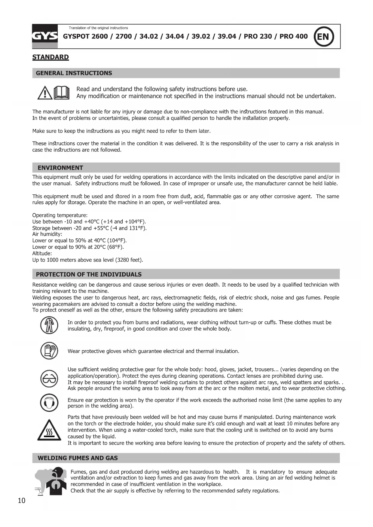
- GYSPOT 34.04 / 39.04 / Pro 400 : The material is supplied with a 16A plug type CEE7/7 and must only be used on a two-phase electrical installation 400 V( 50 - 60 Hz) with 3 wires including one connected to earth. (Zmax = 0.77Ω)
The permanent current absorbed (I1p or ILp) displayed in the section «technical specifications» of this manual relates to use at maximum power. Check that the power supply and its protection (fuse and/or circuit breaker) are compatible with the current needed by the machine. In some countries, it may be necessary to change the plug to allow the use at maximum settings.
NB: If the product trips the circuit breaker, please check that the correct fuse and an adequate circuit breaker are being used.
OPERATING AND SETTING (FIG III-PAGE 2)
A - Gyspot 39.02 / Gyspot 39.04 / Gyspot Pro 230 / Gyspot Pro 400
- Connect the machine to an appropriate power supply
- Connect the gun with its connector.
Nb: Pro 230 and Pro 400 have, in addition to the power connector, a connector to command the torch trigger:
- Connect the latter if you wish to start by using the trigger.
-
Disconnect it if you prefer using the generator with automatic start (see OPERATION section).
-
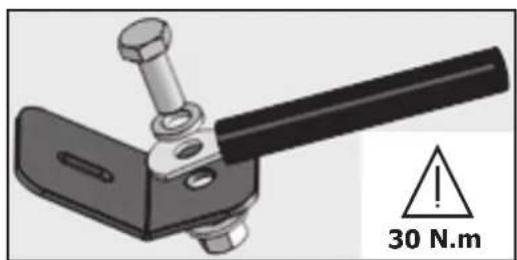
Press the « on/off » key ( 6).
-
The indicators switch on for few seconds then the machine displays:
-
Too, n°1 by default, (star welding or dent pulling clamp).
-
②, Power level, n^05 by default, (setting adapted for 0.8mm steel sheets).
-
To change the power level, press the + or - keys ③. Keep the desired key pressed to scroll through the levels automatically.
The available power levels allow the straightening of sheets of varying thickness (fig IV- A). - To change the tool used with the gun, press the tool selection key ④. The tool indicator will blink for 5 seconds. During this time, it is possible to change the tool number by pressing the + or - keys (③).
Available Tools (fig. IV- B)
| 1 | Straightening using the star hammer, or dent pulling clamp. | 5 W | Welding rivets for side rods |
| 2 | Crimped welding wire or rings for straightening | 6 | Welding rings for fixing vehicle body. |
| 3 | Impact reduction with specific copper tip | 7 | Welding studs for vehicle body and connecting beams |
| 4 | Carbon electrode for tempering |
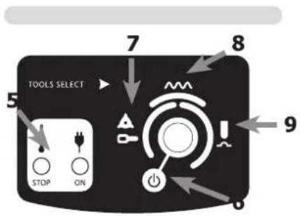
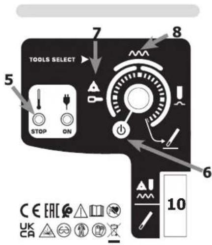
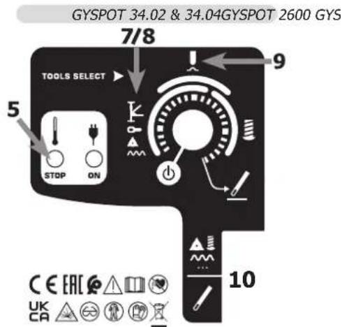
B-Gyspot 2600/2700/34.02/34.04
- Connect the machine to an appropriate power supply,
To start the equipment, turn on the potentiometer. Put the potentiometer on O for standby mode (6). -
Select the start mode using the potentiometer:
-
Range 6 (left): star or ring welding for sheet stretching.
- Range 7 (top): corrugated wire welding, ideal for curved areas.
-
Range 8 (right): Dent pulling work with the adapted copper tip.
-
To change the power level, rotate the potentiometer up to the required power.
OPERATING
1- Start-up
Gyspot Pro 230 / Pro 400
The Gyspot Pro 230 and Pro 400 have 2 settings:
Manual, by using the trigger (Plug the power and command connectors)
On manual mode, connect the power and trigger command connectors.
Automatic mode is disabled, only pressure on the trigger will create the arc. The switch enables to activate or deactivate the trigger gun.
GYSPOT 2600 / 39.02 / 39.04 / Pro 230 / Pro 400 - AUTOMATIC
The machine is able to create the welding arc automatically. The generator will automatically detect the electrical contact and create the welding arc in less than 1 second. To create a new arc, stop the contact with the gun tip for at least 12 second and establish contact again to form another arc.
Gyspot 2700 / 34.02 / 34.04
This generator is equipped with a trigger operated gun for manual operation. A switch enables the activation of the function « graphite pencil » (knob 10).
The potentiometer has 2 ranges of application according to the position of knob 10. One for the graphite pencil and the second for the other tools.
When starting the device, if the yellow light flashes « STOP » (every half second), this indicates either the gun trigger is depressed or there is a fault in the gun cable.
2- How to operate:
Follow the process:
-
Connect the earth clamp of the generator to the sheet metal to be straightened and follow the instructions below:
-
Connect it as close as possible to the place to be welded.
-
DO NOT connect it to a different part of the car body.
(Example: Do not connect it on the door when working on the wing)
-
Ensure the metal has been properly stripped at the connection point.
-
Strip the area where the metal is to be worked.
- Attach the required tool to the end of the gun.
- Select the tool and the power level (see "Operating and Setting") on the machine
- Make contact between the tool on the gun and the metal.
- Generate your welding arc.

Caution: For optimum operation, it is recommended to use the delivered earth cable and gun originally supplied.
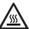
THERMAL PROTECTION
The machine is provided with an automatic thermal protection system, which will stop the machine to prevent it from overheating. When the Thermal Protection Indicator illuminates, leave the machine to cool down.
WARRANTY
The warranty covers faulty workmanship for 2 years from the date of purchase (parts and labour).
The warranty does not cover:
- Transit damage.
- Normal wear of parts (eg.: cables, clamps, etc..).
- Damages due to misuse (power supply error, dropping of equipment, disassembling).
- Environment related failures (pollution, rust, dust).
In case of failure, return the unit to your distributor together with:
- The proof of purchase (receipt etc ...)
- A description of the fault reported
NORM
ALLGEMEIN

B-Gyspot 2600/2700/34.02/34.04
B-Gyspot 2600/2700/34.02/34.04
I3MeHHeHn npMOHT, He yka3aHHbE B 3ToN INHCTpyKcUN, He DOJXhbl 6bITb npeDnPNHrTbI.
Pon3BODNTeH He HecET OTBeTCTBeHHOCTn 3a TpaBMbl MaTePnaJIbHbIe NOBpeKdEHNc CBraHHbIe C HeCOOTBeTCTBYIOUM DaHHOH IHCTpyKcIMN HCNoJIb3OBaHHem annapata.
B cnlyae npo6nemblnn comHeHn, 6paTntecb K KBaIIINΦIuPobAHHomy cneuaIncty nlaipabunbHorO ncnoJb3OBaHn yCTaHOBNK.
CoxpaHnTe daHHyIO nHCTpyKcIHO, yTO6bI npi Hado6HoCTne ee nepeuHTaTb
AnHHbIe HHTpyKun KacaiotcB o6pyoBaHn B TOM COCTOHN, B KOtOpom erO DocTaBUN. Nolb3oBaTeJb DOJKeH npOBecTN anAHIN3 pncOB B clyaee Heco6JIIOHeH N aHHbx INHTpyKUn.
OKPYKAIOUCA PEDA
3To 060pyoBaanHe doJxho 6bTb nCnOJb3OBaHO NCKIIOHTeBHO IJIc CBAPOHyX pa6OT, orpaHnUBArc yka3aHnMn 3aBOckO Ta6IuKn H/INn INCTpykun. Heo6xoIMo CO6IIOaTb DnpeKTNBbl no MepaM 6e3OnacHocTN. B Cnyae HeHaadNexKaUero nn OnaCHOr NCnOJb3OBaHNr pON3BOJNTJIb He HeceT OTBeTCTBEHNOCTN.
AnnapaTdoJIkeH6bITb yCTaHOBJIeH B NOMEueHH 6e3 nbIIN, KcNcIbI, Bo3ropaembIX ra3OB, INI INpyHX KoppO3nHbIX BeueCTB.
Takne je ycnoBna donxHbI 6bITb co6nOeHbI dner erO xpaHeHHa. Y6eNTecB B npncyTCTBn BeHTnlaun npn nCnoB3oBaHN annapata.
TemnepaTyPbIe npedeJIbI:
Bo3dienCTBnE 3neKtpomarHHTHO nOBA B npocce CBapKn MoKeT NMeTb N DpyrNe, eue He H3BeCThIe HayKe, nocJeCTBnI dN 3OpOBb.
PEKOMEHDAUINIJL OUEHKN 3OHbICBAPKN I CBAPOUHOYCTAHOBKN
06nne noJoxeHn
Iolb3oBateIb OTBeueaET 3a yCTaHOBky I nCnOJb3oBAHne aannapata KOHTaKTHOH CBAPKn, CNeyra Yka3aHnM npOn3BOUnteJI.
Pn6hApYkeHHN 3eKTPomarHHTbIX N3lyueHHN NOB3oBATEIb annapaT a KHTaKTHOH CBAPKn DOJKeH pa3peWITb np6IeMy C
nOMOuBIO TexHnueckON IOdEepKKn ppon3BOUnteJI. B HeKOTOpbIX cLyayx 3TO KoppeKTpyUooee DeIcTBNE MoXET 6bITb DOCTaTOUHO
npocTbIM, HAnpIMep 3aemHeHne CBAPouHoi CEnn. B dpynx cnyaax BO3MOXHO NOTpe6yeTc CO3DAHne 3eKTPomarHHTHO 3kpaHa
BOKpyr IVToCHnKa CBAPouHOrO TOKa I Bce CBAPINBaEMO JEtAIn NYTEM MOHTIPOBAHn BXODHBIX fNtPB. B IIO6OM cUYae
3eKTPomarHHTbIe IN3lyueHHN DOJKNHbI 6bITb YMeHbWeHbI TaK, YTO6bl OH N60JIbe He Co3DaBAln NOMex.
OueHka 30HbCbApKu
Ipepe yctahOBkoBOpdyobAHn KOnTaKTHoCBAPKnNoJIb3OBATeNb DoJIkeH OceHNb BO3MOXHbE 3NeKtpomarHHTbIe np6JEMbl, KOtOpBle MOry BO3HKNHYb B OKpykaIOSeI cpe. CJeDyIOUne MOMeTb IOnKHbI 6bITb PnHrTb BO BNHaHHe:
a) NaIiue He, nOd IIN PRAOM C O6OpyIDoBaHHeM KOHTaKTHo CBapKn, dpynx Ka6eJe NITaHn, ynpabLeHn, cHnHaII3aun IN Telefoha;
b) npneMHnKn n nepeDaTChKn paDIO n TeleBnEHHa;
c) KOMnbIOTepbI n dpyrHe yCTpOHTBa ynpabNeHnra;
d) 60pyoobAHne IJIe 63onacHOCTn, Hapmep, 3aunTa npomblIeHHoro 60pyoobAHn;
e) 3dopOBBe HaxoJxNcxr No-6n3OCTn IIOeH, HAnpIMep, nCNoIb3yUoxx KApDIOCTMnyTOpbl N yCTPOINCTBa OT rIyXOTbl;
f) INHCTpymeHT, nCNoJIb3yEmbl dIg KaII6pOBKn IIN NIm 3MepeHnIa;
g) NOMEXOCTOINBOCTb DpyrOoOBaHn, HaxOJaeroCnNo6n30ctn.
Iolb3oBateIbdoJxH y6eIITbcB TOM, YTO BCE annapaTbI B NOMeHn COBmectmbl Dpyr C pyrom. 3To MOKET nOTpe6oBaTb co6HIOEHH DOONHHTeJIbHbIX Mep 3aunTbI:
h) onpeeneneHoe Bpemr dH, KOra cbapka nn pyrne pa60tbo MOKHO 6yET BbINONHHTb.
Pa3mepbpaCCMaTpnaBaemOn 30HbCBapKn 3aBnCtOT CTpyKTybpI 3daHnN npyInx pa6oT, KOtOpBIE HEm npOBoJrTa. PaccMaTpNaBaemAn 30Ha MoKeT npocTupTaBc4 3a npedeJIb pa3MeueHn yCTaHOBKn.
OueHka CBapouHoi yCTaHOBKn
IOMIMO OueHKN 30HbI, OueHKa annapaTOB KOHTAKTHOH CBAPKMOXET NOMOy ONpeJENITb N peuNTb Cnyan 3JIeKTpOMarHnTHbIX NOMex. OueHKa n3Jyehn IOnkHa yuNTbIBaTb N3MepeHn B yCNOBnX 3KcNlyatauIN, Ka 3To yka3aHO B CtaTbe 10 CISPR 11. N3MepeHn B yCNOBnX 3KcNlyatauIN MOrYT TAKKe NO3BOJNTb NOdTBePdNTb 3ΦΦeKTHBHOCTb MEP No CMrYeHNIO BO3DeHCTBnA.
PEKOMEHDAUINI NO METOADNIKE CHNXEHHN 3JIeKTPOMAHHTHO N3JnyEHN
a. 06eCTBeHHa CNTema nHTAHn: annapat KOtAKTHO CBAPKn HxKHO NODKJIIOUHTb K O6IeCTBeHHo CeTn NITAHn, cIeYy peKOMHeAaunm npOn3BODInTeJ. B cnYae BO3HKnHOBEHnN NOMex BO3MOXHO 6yDet Heo6xoIMo PpINrTa DOnONHtEbnHbIe PpeDynpdntelhBiye Mepbl, TaKne KaK fNtBpaunia O6IeCTBeHHo CNCTeMbl NITAHn. Bo3MOXHO 3aUNTTb UHPrNITAHn aannapata C NOMOsbIO 3kpaHN3pyUOSe onlETKN, IIN6o NOXKMn PnCNCOCBHeHnEM (B cnYae eCNn annapat KOtAKTHO CBAPKn NOCTOHN HO HaxOHTcna Ha ONpeDeHempanpoohem MeTe). Heo6xoIMo 06cNeuTb 3LeKTPnueckyu HnpepbIBHOCTb 3KpaHN3nyUoeonlETKN IO BcEN Heo6xoIMo NOcoEHNHTb 3KpaHN3pyUOyIOIETKY K INCTOHNK CyBaOpHOrTOKa dNra ObecneueHn XopoWero 3JeKTPnueeCKORA KOHTAKTA MEXdy IUnPOM IN KOpynCOM INCTOHNKA CBaOpHOrTOKa.
b. Texo6cIyKunBaHne annapata KOHTAIOB CBApKn: annapat KOHTAIOB CBAPKn HxNHO Heo6xOIMO nepnoDnueckn 06cIyKunBaTb corlachO peKOMeHdaCnM npOn3BOIDTeJIa. Heo6xOIMO, yTo6bI BCE DOCTynbl, IIOKN OTKNbIBaIOUncEcaTn KOpNya 6bln 3akpbItbI npabInbHo 3akpenIeHbI, kOrDa annapat KOHTAIOB CBAPKn rOTOB K pa6ote nIN HaxODNTcB Pa6oYem CoCTOHN. Heo6xOIMO, yTo6bl annapat KOHTAIOB CBAPKn He 6bln nepeDeJah KaKIM 6bl TO HN 6blIO o6pa3OM, 3a NCKNIouHeHem HAcTPOEK, YkazAHhIX B pyKOBOIDCTBE npOn3BOIDTeJIa.
c. Cbapouhble ka6e: ka6eI doJxHb 6bITb Ka KMOXHO KOPOe I NOMEueHb dpyr praDM c Dpyrom B6n3n OT NOla nIu Ha noIy.
d. 3KBHnToeHuaJIbHbIe CoeHHeHH: Heo6xOJIMo O6ecneHTb CoeHNHeHHe BCEx MeaJIInuecknx npEeMeTob OKpyXauOeien 30Hb. TeM He MeHee, MetaJIInueckne IpeMeTbI, CoeHNHeHbIe CO CBapINBaEMoI dTaIbIO, YBeJIuNBAOT PnCK Ira NIOB3OBaTeJIy yDapa 3NeKTPnueckm TOKOM, eCIN OH OndHOBpeMeHHO KcHETcR 3Tnx MeaJIInuecknx npEeMeTob IN 3NeKTpOda. OepaTop DoJKeH 6bITb I3OJIIpOBaH OH TaNX MetaJIInuecknx npEeMeTob.
e. 3a3emleHne CBapnBaemoi DetanB: B Cnyae, ecn CBapnBaemai Detanb He 3a3emIeHa No COo6paJxHm EJIeKTPuuecko 6e3onacHocTn nIn B Cnly CBOIX pa3mepoB n CBOero paCnoNIOKeHnA, KAK, HAnpImep, B Cnyae KopNyca CyDHa nIn MeTANLOKOHCTpyKUIN npomblJeHHoro o6BekTA, To coEINHeHne Detanl C 3eMNe, MoKet B HEKOToPbIX CnyaAx, HO He CNCTeMaTHueCKn, COKpaNTb Bbl6pOcbI. Heo6xoDMIO n36eRaTB 3a3emHne Detanei, KOToPbIE MOrII bblyBvEnuHTb Ira NOnb3OBaTeJe pNcKn paHeHNI JIn Jx NobpeDHT dpYtne 3eKTPooyCTahOBKn. Ppi HAdo6HocTn, CledyET HAprrMyIO NOCoEINHTb DeTaIb K 3eMLe, HO B HeKOToPbIX cTpaHax, KOToPbIE He pa3peSIAOT npAmoe noCoEHNHeHne, erO HyXHO CDeNaTb C NOMOUsHO NOxOJaero KOHDeHCaTopa, Bbl6paHHoro B 3aBNCIMOCtN OT 3aKHOdaTeNBCTBa CTpaHbl.
f. 3aunTa n 3kpaHn3npuOaonlTeKa: Bb6OpOHaHa 3aunTa n 3kpaHn3npUoA onlTeKa dpyrHex Ka6enei n 06OpyDoBaHn, HaxoJxxCB B 6nI3Jekaem pa6oHem yactke, NOMoKet orpAHuHTb np6IeMblcBraHHbIe C nomexAmn. 3aunTa BCEn CBapOHO 30Hb MoKet paccMaTpuBaTbcR B HeKOToPbIX Oco6bIX clyuaRx.
TPAHCIOPTNPOBKA IN TPAH3NT NCTOCHNKA CBAPOHORO TOKAK

NcOHTHnKa CBAPOHOro ToKa OCHaSeH pyKoI IaTpaHCnpTnOBKn,IO3BOJIAUIMNIpeHocITb annapat. ByTe BHNMaTeNbHbI: He HeDOooCeHNBaIte Be cAnnapata.Pyka He MoKet 6bItb NcNoB3ObaHa dIra CTponOBKn.
He noIb3yItecb Ka6eIaMn Ira nepemueHna NCTOCHNka CBAPoHoro TOKa.
He npeHocuTb hctOHHK TOKa HaI JIOdbMn NII ppeMeTaMn.
YCTAHOBKA ANIAPATA
-Ппсдсмтпг ДОCTАТУН 60ьшоe npoctpaHCTBO ДЯ Xopoшero npoBeTpBaHnЯ nToCHNka CBapOCHOrTo Toka N DoCTyNA K ynpabNeHIO.
He nCnoIb3oBaTb B cpe de codepkaue MeTaJIInueckyIO nbIb-tpOBoNDHK.
- UHyp nHTAHnIy, ydInHnteIb I CBapOchIb Ka6eJIb DoJXHbI NOJHOCTbIO pa3MOTaHb BO n36exaHne nepepeBa.

Ipn3BODNTelb He Hecet OTBeTCTBENHO TOTHCnTeJbHo yuepe6a,HaHeceHHOrO IuIaM IIN npEmdTaM,I3-3a HenpaBnBHorO n Onachoro NcNoJIb3OBaHnA 3TOrO 6OpdyoBaHnA.
OBCLNYKINBAHNE / COBETbl

Bapntb KOHTAKTHOH CBAPKO MORYT TOnIbKO KBAHINPHUPOBaHHbIe CneuaJIACtBi, CneuaJIbHO 06yueHHble dIpa60tbc daHHbIM annapaTOM c TEM, yTO6bi NCIOJIb3OBA Tb BCE erO BO3MOXHOCTn I npON3BOJNTb CBAPOUHbIE pa60tbc corlaCHO npabunam HOpMaM (HaNPmep: cnecapb NO KY3OBHOMy peMOHTy).
- Npeed tem, kak npnctynntb K pemOHry aBtOMO6nIy, npOBepbTe, yTo aBTOpON3BODInTeIb OOn6pReT nCIOJIb3yEmbMyMeTOc CBapKn.
- Texo6cnyxnbAHne n peMOHT nCTOCHnka MoryT npOn3BOOntbcra TOnbKO npOn3BOOnTeJIeM. IIO6a onepauHnHaN HCOPeHHnA NOCTOpOHnM LIuOM, AToMaTmueckn OTMeHnEeR rapaHTIO. PpOn3BOOnTeJIb CHImaet C Ce6y BCaKyIO OTBeTCTBeHHOCTB 3a HeCuaCTHbIe clyan, pOnCSeUdne BCNeDCTBHe 3TOrO DeiCTBnI.
- OTKIIOHTe PNTAHne, BbIDepHyB BVJIKy I3 PO3eTKN, IN DOXdITecb OCTaHOBKn BEHTINrTopa nepeD TeM, KAK pNCTyINrTB K TEXO6CnyKBAHnIO. BHyTpN annapata BbICOKNe n OnaChbIe HAnpJKeHne n TOK.
JIIO6bI CBAPOHyBIE AKECEcyapBI NOBpeKDAHOTcPn HcNOJb3oBAHN.CJeINTe 3a TeM,HTo6bI 3TN AKECEcyapBI 6blIN YNCTbIMN, TTO6bl NCTOCHK BCERda pa60taJ Ha MaKCMYM CBOIX BO3MOKHOCTeJ. - Ipeed nCnoB3OBAHnEM nCtoIeta npOBepaTe COCTOHNpe pa3nUHbIX aKCECCyapOB (3Be3DOUka, 3JIeKTPOd IJRA OJHOCTOPOHHe CBAPKN, yROHbN 3JIeKTPOD IN T.D.), OHuaTe IN NIN 3aMeHnTe, eCNIO Hn B PNOXOM COCTOHN.
- Perynphno OTKpbBaIte annapat n npOyBaIte erO, YTO6bl OCHNTb OT nbll. Heo6xOIMO TAKKe npOBepaB BCE 3JIeKTPueckne coeHNHcN C NOMOuHIO I3OINPOBaHHORO INCTpyMeHTa. IpOBepKa DOJIXHa OCyUeCTBnTbC KBAJINQUPOBAHbIM CNEuaNlntOM.
- Perynapno npOBepaTe COCTOHN He HHPa NHTAHN IN Pykaba CBAPoHOn cenn. Ecn Ha 3TNx DeTAnX BNDbI NOBpeKdHn, To OHn DOJKNbI 6bITb 3AmHeHbI IPOIN3BOIDInTelem, erO cepBnCHOn CnyK60I IN KBAInΦnUpOBaHHbIM CneuaJIvCTOM BO n36ExKaHne onaCHOCTn.
- OctablaIe OTBepTnA hCTOuHnKa CBAPoHOro TOKa CBO6OdHbIMn IIN pPOXoJKeHn BO3Dyxa.
NHCTPYKUN
ONHCAHNE
3TN annapaTb pa3pa6oTaHb InI npOBeHn CneDyUOxN Ky3OBhix pa60T: PpaBka Ky3OBA; npBapKa rBo3dei, 3akJeNoK, Wai6, uInleK mOndHroB; yCTpaHeHne BMrTH, BbIPaBHnBaHne NOBepXHOCTN. OHn He npEHa3HaYeHbI dJa pa60T no CoedHHeHIO MetaIIuuecknx DeTaJIe. 3TN annapaTb nocTabIOTcB KOMPJIeKTe CO CNeDeYIOUMn akceccyapaMn:
| АкCEDсары 2600 | 2700 | 34.0234.04 | 39.0239.04 | PRO 230PRO 400 |
| Пл actина мась | ✓✓✓ | |||
| Кабел постолетаotденьberry | ✓ | ✓ | ||
| Ак sceccуapbl 2600 | 2700 | 34.02 34.04 | 39.02 39.04 | PRO 230 PRO 400 |
| Automatic Quick Gun | ✓✓✓ | |||
| Manual Quick Gun | ✓ | ✓ | ||
| Spotter Box | ✓ | |||
| Spotter Box Pro | ✓ |
NODKJIIOUOHENE K CETN
3ANYCK ANIAPATA N HACTPOIKN (PNC III)
A - Gyspot 39.02 / 39.04 / Pro 230 / Pro 400
Bknouhte annapat B COOTBEcTBYIOU 3JIeKTPnueCKyIO cTe, 3aTeM nOcOeHNHTe NICTOJET K annapTy C nOMoIbIO pa3bema Ha 1 / 4 o6opota.
- Pódklouchite nictoJet c nOMOuBJ KOHHeKTopa.
Nb:Pro 230 n Pro 400 mMeIOT nommo KOHHeKTopa MoUHOCTn, KOHHeKTop ynpabLeHHa Kypka :
- Pooknohte KypkoBoe ynpaBneHne, eCN Bbl XOTnTe OcyueeCTBnTB nOxNIG C NOMoBuKypKa.
-
OTKIIOUHTe erO, ecIN Bbl XOTnTe HcNoJIb3OBaTb rEHePaTOP B peXHMe aBTOMaTHueCKORo NOJXnra (cm. pa3dEn HcNOJIb3OBAHNE)
-
HaKmTe Ha KhoNkY «Bkn/Byikn» (6).
-
3KpaH n CBeToNDIObI 3aRopAOITcHa KOpOTKoe BpEm, 3aTeM annapaT NOKa3bIbaeT :
-
① INHCTpymEnT (N01 no yMolbuaHnIO) : npuBapka 3Be3doueK nIN NcNoIb3ObaHne 3axmJa DJI BbITraBaHnMa MEIKNX BMrTnH n rpaDa.
-
② ypoBHeH MOUHOCTn (N95 no yMOJIbUaHnIO) : (napaMeTp dIra pa6OtBi C Jxene3HbIM IInCTOM do 0,8 MM).
-
UTo6bI n3MeHnTb MoUHOCtB, HauKmnte Ha KHONK + nIN - ③. EcIn NoDJIepKuBaTb HaKaTOI ONDy IN3 3TNX DByX KHOJOK, n3MeHeHne yPOBeHr MOUHOCtN 6yDET pOncxOJNTb B 6eRJOM peXIMe.
- PnpdycmToHHbIe ypoBHm MOHocTHn PO3BOJIAOT pa6oTaTb C Ky3OBAMn pa3HOJ TOJIuINHbI (Pnc IV- A).
- UTo6bI CMeHnTb TIN NcNoJIb3yEmOro IHCTpyMeHTa, HaxMInTe Ha KhoNkyl 4.
Yka3aTeIb Homepa INHCTpyMeHTa Mopraet B TeueHne 5 cek. Bo BpeM daHHo nay3bl BO3MOxHO nOmeHrTb Homep INHCTpyMeHry, HAKIMAR Ha KONKn « +» n « -» (③).
NCTpymEntbI (Pnc. IV- 8)
B-Gyspot 2600/2700/34.02/34.04
-Подклочи Te annapaT K COOTBeTCTBHyOuIeMу 3JIeKTpUYeCKOMy NITaHnIO,
-Дя GYSPOT 2600/2700/34.02/34.04 3anyckВ pa6Oу OcyuecTBnErcy NOBOPOTOM NOTeHcNoMeTp a (peKIM OxuaHry - Bo3Bpa TnoTeHcNoMeTp a B no3uio 0). (6)
- Bb6epnte pa6oyn pexm c nmoaio noTeHnOmeTpapeylnpOBKn: