232163 - Freezer Arktic - Free user manual and instructions
Find the device manual for free 232163 Arktic in PDF.

| Product type | Blast chiller & freezer |
| Brand | Arktic |
| Model | 232163 |
| Dimensions (W x D x H, including legs) | 750 x 740 x 720 mm |
| Net weight | 50 kg |
| Power supply | 230 V – 1 Ph – 50 Hz |
| Power consumption | 1150 W |
| Refrigerant | R404a / R507 (flammable) |
| Cooling capacity (from +70 °C to +3 °C) | 14 kg / cycle |
| Freezing capacity (from +70 °C to -18 °C) | 11 kg / cycle |
| Number of racks | 3 x GN 1/1 or 3 x 600x400 mm |
| Rack spacing | 70 mm |
| Storage temperature range | 0 °C to +4 °C (positive) / -22 °C to -25 °C (negative) |
| Control panel | Digital with LED display, SET, UP, DOWN, START/STOP buttons |
| Main functions | Positive chilling, negative freezing, core probe, cycle programming, holding, manual defrost |
| Defrost | Manual, without heating – door open or closed |
| Exterior material | Stainless steel |
| Minimum distance to wall | 100 mm |
| Compressor protection | Delay between stop and restart: 2 min (adjustable) |
| Maintenance and cleaning | Clean daily with warm water and a non-aggressive detergent; do not use abrasive or chlorine-based products |
| Warranty | 12 months from the date of purchase |
| Use | Professional use (kitchens, bars) |
| Country of manufacture | Not specified in the manual |
| Repairability | Spare parts available on request (model and serial number required) |
Frequently Asked Questions - 232163 Arktic
User questions about 232163 Arktic
0 question about this device. Answer the ones you know or ask your own.
Ask a new question about this device
Download the instructions for your Freezer in PDF format for free! Find your manual 232163 - Arktic and take your electronic device back in hand. On this page are published all the documents necessary for the use of your device. 232163 by Arktic.
USER MANUAL 232163 Arktic
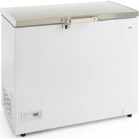
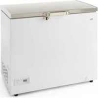
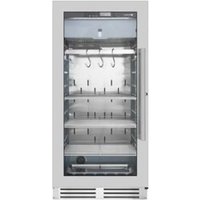
natural_image
Exterior view of a white industrial oven with two black fans and a control panel (no visible text or symbols)Item: 232163
232170
232187
232194
232491
232507
You should read this user manual carefully before using the appliance.
Keep these instructions with the appliance.
natural_image
Simple line drawing of a house with an arrow pointing left, labeled 'INDOOR' below (no other text or symbols)For indoor use only.


Thank you for purchasing this Hendi appliance. Before using the appliance for the first time, please read this manual carefully, paying particular attention to the safety regulations outlined below.
1. Safety regulations
- This appliance is intended for commercial use only and must not be used for household use.
- The appliance must only be used for the purpose for which it was intended and designed. The manufacturer is not liable for any damage caused by incorrect operation and improper use.
- Keep the appliance and electrical plug away from water and any other liquids. In the event that the appliance should fall into water, immediately remove plug from the socket and do not use until the appliance has been checked by a certified technician. Failure to follow these instructions could cause a risk to lives.
- Never attempt to open the casing of the appliance yourself.
- Do not insert any objects in the casing of the appliance.
- Do not touch the plug with wet or damp hands.
- Danger of electric shock! Do not attempt to repair the appliance yourself. In case of malfunctions, repairs are to be conducted by qualified personnel only.
- Never use a damaged appliance! Disconnect the appliance from the electrical outlet and contact the retailer if it is damaged.
- Warning! Do not immerse the electrical parts of the appliance in water or other liquids. Never hold the appliance under running water.
- Regularly check the power plug and cord for any damage. If the power plug or power cord is damaged, it must be replaced by a service agent or similarly qualified persons in order to avoid danger or injury.
- Make sure the cord does not come in contact with sharp or hot objects and keep it away from open fire. To pull the plug out of the socket, always pull on the plug and not on the cord.
- Ensure that the cord (or extension cord) is positioned so that it will not cause a trip hazard.
• Always keep an eye on the appliance when in use. - Warning! As long as the plug is in the socket the appliance is connected to the power source.
- Turn off the appliance before pulling the plug out of the socket.
- Never carry the appliance by the cord.
- Do not use any extra devices that are not supplied along with the appliance.
- Only connect the appliance to an electrical outlet with the voltage and frequency mentioned on the appliance label.
-
Connect the power plug to an easily accessible electrical outlet so that in case of emergency the appliance can be unplugged immediately. To completely switch off the appliance pull the power plug out of the electrical outlet.
• Always turn the appliance off before disconnecting the plug. -
Never use accessories other than those recommended by the manufacturer. Failure to do so could pose a safety risk to the user and could damage the appliance. Only use original parts and accessories.
- This appliance is not intended for use by persons (including children) with reduced physical, sensory or mental capabilities, or lack of experience and knowledge.
- This appliance must not be used by children under any circumstances.
- Keep the appliance and its cord out of reach of children.
- Always disconnect the appliance from the mains if it is left unattended or is not in use, and before assembly, disassembly or cleaning.
- Never leave the appliance unattended during use.
2. Special safety regulations
- This appliance is designed for quick chilling or freezing prepared dishes. Do not store any other materials in the appliance. Do not place any dangerous products, such as fuel, alcohol, paint, flammable or explosives, etc. inside or near the appliance.
- This appliance must be installed, commissioned and services by a qualified or trained person. And this appliance is intended to be used by trained or qualified personnel such as kitchen or bar staff.
- WARNING: Do not use mechanical devices or other means to accelerate the defrosting process, other than those recommended by the manufacturer.
- WARNING: Do not damage the refrigerant circuit.
- Caution! Risk of fire! The refrigerant used is R404a or R507 in this appliance. It is a highly flammable refrigerant.
- WARNING: Keep all ventilation openings in the appliance enclosure clear of obstruction. Provide sufficient ventilation in the surrounding structure when building-in.
- WARNING: Do not use electrical appliances inside the food storage compartments of the appliance, unless they are of the type recommended by the manufacturer.
- Place the appliance on a clean, stable, dry, level surface only.
- Keep the appliance away from any hot surfaces and open flames. Protect the appliance against heat, dust, direct sunlight, moisture, dripping and splashing water.
- Allow at least 10 cm surrounding spacing for ventilation purpose during use.
- Do not place articles on top of the appliance. Do not place objects with open sources of fire (e.g. candles) on top or beside the appliance. Do not place objects filled with water (e.g. vases) on or near the appliance.
- Never cover the appliance during use. This may cause a fire hazard.
- Do not wash the appliance with water. Washing can cause leakages and increase the risk of electric shock.
- Do not make any additional openings on the appliance. Do not install any gadgets in the appliance.
- Do not overload the shelves inside to avoid damage. Max. loading of each shelf is about 4 kg. Place the food evenly on each shelf.
3. Introduction
Positioning of blast chiller
Before unloading/loading and positioning the blast chiller inside the shop/kitchen, you are kindly requested to read carefully the instruction manual in the different chapters regarding the unloading/
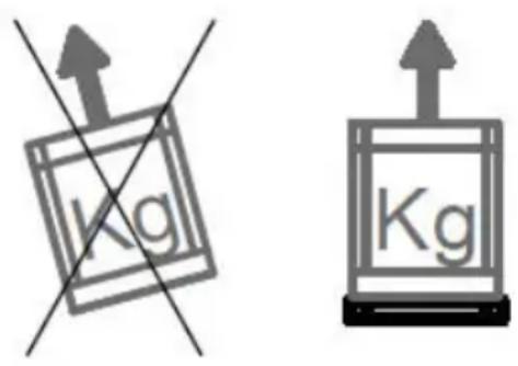
Transport
Do not superimpose blast chiller packing (allowed only if there is wooden crate packing option). We recommend you to transport the blast chiller always in the upright position (as mention on the packing). If the blast chiller with built in condensing unit was inclined during transportation we suggest you to keep the product in the suggested upright position for at least 8 hours, before switching it on. In this way, you will allow the oil to flow in all the components, lubricating them again. Afterwards you can proceed with the start.
Unloading/ Dimensions/ Weight
The unloading/loading procedures should be executed by pallet-jack or by forklift driven by skilled and authorized staff. We decline any liability for failing to comply with safety rules currently in force. Before starting the unloading, positioning and installation procedures of the blast chiller freezer
Packing
At the delivery please check that the packing is intact and that during transportation no damage was occurred. Remove the external carton-box; remove the fastener that keeps still the blast chiller/freezer to its pallet, put it in the correct position and then remove the adhesive white protection of the stain-
Condensate water draining / draining connection
The blast chiller is available with a built in condensing unit complete with a removable condensate water basin with manual defrost (without defrost heat-
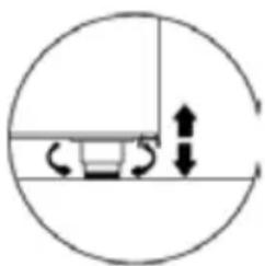
Positioning and feet regulation
Place the blast chiller in a perfect horizontal position, acting if necessary on the screw type adjustable feet. Use a spirit level to check it. The blast chiller must be placed in order to operate properly and allow the correct defrost condensate water drainloading, dimensions, weight, evaporating water basin, adjustable feet, electric connections and maintenance procedures of the blast chiller subjected in the present manual.
inside the shop/kitchen according to the model of the blast chiller, please read carefully the information showed in the dimensions and weights list.
The manufacturer declines any responsibilities due to operations performed without adopting the above safety precautions.
less steel. The recovery and the recycling of the packing materials such us, plastic, iron, carton box, wood help the saving of row material and reduce the waste. Please consult your area address book for disposal of materials and authorized garbage dump.
er). The basin is assembled in the lower part, under the condensing unit.
ing. In this way you will avoid noisy vibrations of the condensing unit. Check the correct positioning of the condensate water basin and its draining.
natural_image
Simple circular diagram with a horizontal line, a circular arrow, and a circular base, no text or symbols present.Installation inside your shop
We suggest you to install the blast chiller/freezer inside an air-conditioned room. We kindly remind you that without this facility, malfunction may occur (for example condensation etc).

ATTENTION!
In order to allow a good functioning of the blast chiller/freezer please draw attentions to the following instructions.
- Do not place the blast chiller to a direct exposure of sunlight and to all the other means of irradiation, such as high intensity incandescent lights, cooking ovens, heating radiators.
- Do not place the blast chiller close to external exits into draught, such as doors, windows, air vent or air conditioning fans.
-
Do not obstruct the blast chiller air inlet.
-
Do not place any kind of material on the blast chiller. Keep clear the whole blast chiller perimeter in order to allow a proper air circulation.
- Do no place the blast chiller into an high relative humidity room (condensate water creation is possible)
- Do not place the blast chiller inside a closed cavity. Without a proper air circulation the refrigeration unit will not work efficiently.
- Do not place hot trays or pans on the top of the blast chiller.
Verify that in the installation room there is enough air turnover, even during closing and rest hours. In this way the expansion/condensing unit will work correctly.
Minimum wall distance

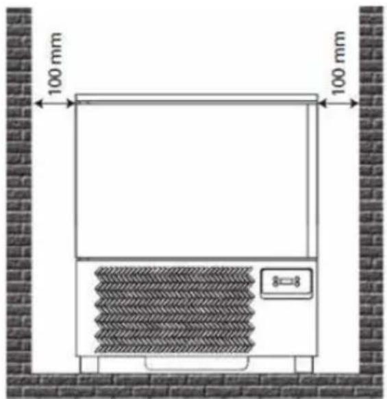
In order to allow a good blast chiller functioning and a correct air circulation, during the positioning you have to respect some minimum wall distance as follows:
Blast chiller with built in condensing unit
The blast chiller is provided with built in condensing unit, therefore it is necessary not to obstruct the blast chiller air inlet corresponding to the front grid for the air extraction in order to allow a proper air circulation. Keep clear the whole blast chiller perimeter. We remind you that room temperature rises or insufficient quantity of air to the unit condenser, reduce the blast chiller performances with
natural_image
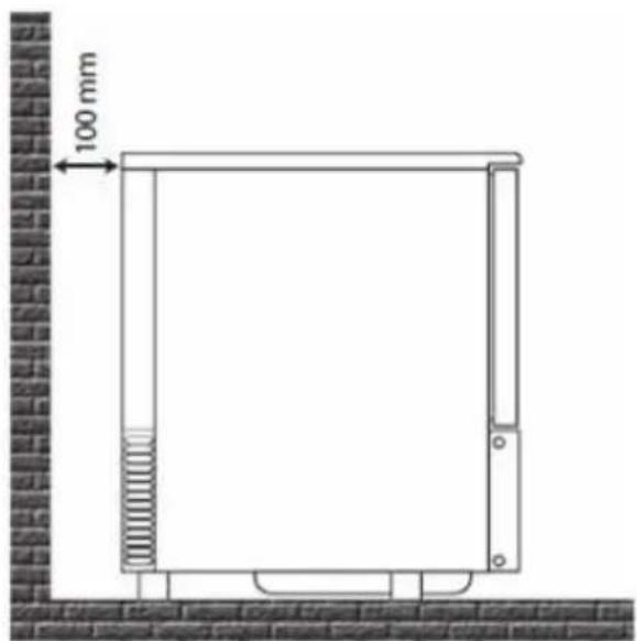
Technical line drawing of a rectangular enclosure with a spring and wall-mounted base, no text or symbols present- Keep a minimum distance, corresponding to the door opening length, from the front unit grid view.
- Keep a minimum 10 cm distance of the blast chiller back from the wall.
possible deterioration of the products and more energy consumption. If the blast chiller with built in condensing unit was leant on the side during transportation we suggest you to keep the product in upright position for at least 8 hours, before switching it on. In this way, you will allow the oil to flow in all the components, lubricating them again. Afterwards you can proceed with the starting.
Technical data
| 232163 | 232170 | 232194 | 232187 | 232491 | 232507 | |
| Dimensions [WxDxH mm] (with feet) | 750x740x720 (750) | 750x740x850 (880) | 750x740x1260 (1290) | 750x740x1260 (1290) | 750x740x1850 | 750x740x2080 |
| Net weight [kg] | 50 | 71 | 90 | 102 | 120 | 150 |
| Chamber dimensions [WxDxH mm] | 600x400x280 | 610x400x410 | 760x630x410 | 760x630x410 | 610x410x1120 | 610x410x1360 |
| Capacity [No. of tray] | 3x GN 1/1 or 3x 600x400 mm | 3x GN 1/1 or 3x 600x400 mm | 3x GN 1/1 or 3x 600x400 mm | 3x GN 1/1 or 3x 600x400 mm | 3x GN 1/1 or 3x 600x400 mm | 3x GN 1/1 or 3x 60Ox400 mm |
| Space between trays [mm] | 70 70 105 70 70 70 | |||||
| Blast chilling performance [+3°C] | 14 kg 20 kg 25 kg 25 kg 45 kg 50 kg | |||||
| Blast freezing performance [+18°C] | 11 kg 15 kg | 20 kg 20 kg 35 kg 40 kg | ||||
| Gas [Type] | R404a/R507 R404a/R507 R404a/R507 R404a/R507 R507 | R507 | ||||
| Test details [°C / RH] | +43 / 65% | +43 / 65% | +43 / 65% | +43 / 65% | +43 / 65% | +43 / 65% |
| Absorbed power [W] | 1150 | 1424 | 1490 | 1490 | 1820 | 2040 |
| Power supply [V-P-Hz] | 230-I-50 | 230-I-50 | 230-I-50 | 230-I-50 | 400-3-50 | 400-3-50 |
The manufacturer and dealer is not liable for any inaccuracies due to printing errors or transcription, in this manual. In line with our policy of continuous improvement products, we reserve the right to
make modification of the product, packaging and specifications contained in the Documentation without prior notice.
4. Electrical connection and earthing
Electrical power supply

The installation and the electrical connections must be carried out in conformity with the electrical rules in
force. These operations must be carried out by qualified staff. The company declines any responsibilities originated from the no observance of the above rules in force.
See the blast chiller electric diagrams at the end of this manual.
Before plugging in the blast chiller, it is necessary to proceed with its complete and careful cleaning, using warm water with no aggressive detergents and drying with a soft cloth all the humid parts (read with attention the chapter regarding the blast chiller cleaning).
In order to carry out a correct plug in you must proceed as follow:
- Prearrange a thermal magnetic circuit breaker switch and be sure that the frequency/tension of the line corresponds to that shown on the blast chiller serial number label (see the label placing).
- Verify the supply tension at the socket, it must be between +/- 10% when you start the compressor.
Starting the blast chiller

ATTENTION!
The first start up must be carried out by qualified staff.
Before switching on the blast chiller, be sure that:
- Your hands must be dry
- The surface of the blast chiller must be dry
- The floor and the electrical socket must be dry
Furthermore, be sure that:
- The build in condensing unit blast chiller must be carried only in upright position. If it had leaned, we recommend to wait at least 8 hours before proceeding with the start so that the oil will flow in all the components, lubricating them again.
For the temperature setting make reference to the
- We recommend you to install a bipolar-switch (or 4 square pole switch) with contact opening of at least 3 mm, at the head of the socket. This switch is obligatory if the loading is over 1000 W or when the blast chiller is connected directly without the use of the plug. The mag thermic switch has to be placed nearby the blast chiller in order to be well seen by the technician in case of maintenance.
It is necessary that the power supply cable section is adequate to the unit power consumption.

The earthing of the appliance is compulsory in conformity with the law. Therefore it is necessary to connect it to an efficient earthing system. If the power supply cable was, it must be substituted by the technical qualified staff. It is strongly recommended to avoid the use of electrical appliance inside the blast chiller compartment.
- If the compressor is damaged, it must be replaced exclusively by qualified staff, in order to prevent any risks. In case of breakdown we suggest to unplug the appliance and to use a high sensitivity mag thermic anti-electrical shock switch.
corresponding chart about product categories/ usage temperature, in addition For the working parameters regulation refer to the user instructions of the control panel enclosed to this current manual.
Once the blast chiller is connected with the power cable (see the previous paragraph), proceed powering it with the switch closing.
For the built in unit, before plugging it in, verify that the selector is open in 0, OFF or green position. Insert the socket and then turn off the switch. Before placing inside the food to be chilled or frozen, it is necessary to clean the chamber of the appliance (see chapter about cleaning) and afterwards it will
be required to chill in advance the chamber before starting the positive or negative processes.
For regulating the functioning parameters consult the instructions for the instrument panel enclosed to the current manual.
5. Cleaning
All the procedures must be carried out with the stationary unit removing the tension from both the re-
Cleaning of the blast chiller
The maintenance of the blast chiller must include at least one daily cleaning of the loading zone, in order to prevent the development and the accumulation of bacteria.
Before cleaning the blast chiller room, carrying out the defrosting keeping the door open and removing the lid of the drainage pipe.

ATTENTION!
It is essential to keep daily clean the blast chiller in order to prevent the development and the accumulation of bacteria. Before cleaning the chamber of the blast chiller, you must execute a defrosting process, by removing the lid of the drainage basin.
- Do not flush directly the inner parts of the blast
Cleaning the probe
The maintenance of the blast chiller must include at least one daily cleaning of the temperature core probe.
It is essential to keep daily clean the blast chiller room probe. All the procedures must be carried out with the stationary unit removing the tension from both the refrigerated item and the condensing unit. We recommend to rinse carefully the probe with clean water and with hygienized solution. Refer to
frigerated item and the condensing unit.
chiller because the electrical parts could get damaged.
- Do not use any hard metal tools to remove the ice.
- For the cleaning use only warm water (not hot) with no-aggressive detergents, taking care of drying the wet parts with a soft cloth.
- Avoid to use products that contain chlorine or diluted solutions, caustic soda, abrasive detergents, muriatic acid, vinegar, bleach or other products that might scratch or grind.
• We recommend to clean the device at least once a month, when it used for deep-frozen products.

Attention, during the cleaning operations it is recommended to use work gloves.
EN

natural_image
Simple line drawing of a hand holding a tool or tool, no text or symbols presentthe same methods and detergents for cleaning named in the previous paragraph.
6. Recommendations and warnings
We recommend to make a daily cleaning of the external part of the blast chiller, including the internal
side of the door near the gaskets.
Manual defrosting
The blast chiller has manual defrosting and can be made with open door or closed door (in this case the time of defrosting will be longer).

ATTENTION!
When the blast chiller has finished the process, it is necessary to remove the lid of the water drainage
Maximum shelf load and storage

ATTENTION!
The blast chiller is suitable to drop the temperature of already cooked food (see the chart with the temperatures according to the products which must be dropped).
Do not introduce into the blast chiller products which are just taken out of the oven. Wait few minutes before placing the products inside the room and then start the cycle. We remind you that the blasting time to reach the requested temperature, depends on different factors such as:
Modalities selection of the process time
The modalities selection of the blast chiller are:
- Time cycle, when the process time is specified. When the time cycle phase finishes, the conservation modality automatically starts.
pipe in order to allow the water draining into the basin. The drainage pipe is useful also for the draining of other liquids from the product.
At the end of the process, check the level of the water and, if it necessary, empty the basin.
- The shape, the type, the thickness and the material in which the food to be chilled is contained.
- The usage of lids above the containers.
- The physical features of the product, density, water and fat contents.
- The temperature condition of the food to be chilled.
The setting of the time for the positive chilling and negative blasting must be set according to the type and the weight of the food to be treated.
- With core probe, it is sufficient to set the temperature of the product to be chilled of frozen; the probe records the temperature and after the acoustic signal the device will pass into the conservation modality (see position of core probe).
| Type of process Type of cycle Type of product | Loadable product | Thicness | Cycle at the product code | |
| Postive Full speed | for dense food or thick size | 4 kg each tray maximum | 50 mm +3°C MAX 90 min | |
| Negative Full Speed | for dense food or thick size | 3 kg 40 min | until -18°C (240min) | |
| - Reduced speed | delicate products,vegetables, crème, sponge dessert, small size products | --- | ||
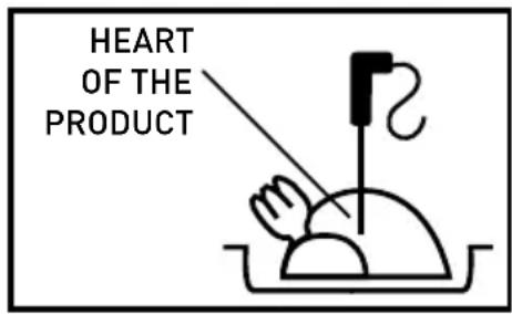
Measuring the temperature at the product core
When the thickness of the products allows it, always use the core probe to know exactly the reached temperature at the product core, and do not interrupt the cycle before the temperature of +3°C and -18°C is reached. For a correct function of the blast chiller, it is necessary that the products contained inside are well placed in the middle, in order to allow a good circulation of the air in the blast chiller. Do not obstruct the blast chiller/freezer air inlets inside the device
For a correct function of the Blast Chiller, it is necessary that the products contained inside are well placed in the middle, in order to allow a good circulation of the air in the Blast Chiller.
Conservation of the food cooked and blast freezed
The food cooked and blast freezed can be preserved in the fridge keeping the organoleptic qualities up to 5 days from the date of treatment.
It is important to respect the cold chain, keeping
Conservation of the food cooked and deep frozen The food cooked and deep frozen can be preserved in the fridge keeping the organoleptic qualities up to several months from the date of treatment. It is important to respect the cold chain, maintaining during the conservation a stead temperature from 0° to 4°C, according to the kind of the food. Using the vacuum technique, the conservation time can be raised until about 15 days.
The food which is subject to negative cycle can be safely preserved for a period of time from 3 to 18 months, according to the food treated.
- It is important to respect the conservation temperature equal or below -20°C.
Blast chiller starting up procedures
Blasting cycle with core probe
- Push the green button.
- Push the button "SET" SET to select the temperature +3°C or -18°C.
- Afterwards, push the button "START/STOP" to start the cycle.
ATTENTION!
Children must be kept away from the Blast Chiller.
during the conservation a stead temperature between 0^ C and 4^ C, according to the food.
Using the technique of vacuum packing, the time of conservation can be raised until about 15 days.
ATTENTION!
- Avoid leaving at room temperature the food cooked and to be blast frozen.
- Avoid humidity loss, at risk of the food fragrance.
The blast frozen food must be protected by a protective film (better if vacuum packed) and provided with adhesive label on which must be indicated:
- The content
• The day of preparation
• The assigned expired date
ATTENTION!
Once the food is defrosted, it cannot be frozen again.
- At the end of the cycle (when the buzzer starts to ring), the machine passes automatically into the conservation phase.
- To stop the cycle, press "START/STOP".
Blasting cycle at time
- Push the green button.
- Push the button "SET" Ⓗ to select the temperature +3°C or -18°C.
-
Afterwards, push the button "UP", +DW" to set the requested time for the blasting cycle.
-
Push the button "START" to start the cycle.
- At the end of the cycle (when the buzzer starts to ring), the machine passes automatically into the conservation phase.
- To stop the cycle, press "START/STOP"
Conservation time (in months) for blast chilled-shock frozen food
In the chart below there are the preservation times of some deep-frozen food.
| Food | Freezing -18°C | Freezing -25°C | Freezing -30°C |
| Dairy products | |||
| Cheese 4 6 6 | |||
| Butter 8 12 15 | |||
| Poultry and meat | |||
| Beef 9 12 18 | |||
| Veal 6 12 18 | |||
| Lamb 6 12 18 | |||
| Pork | 4 | 12 | 15 |
| Poultry | 5-9 | 12 | 18 |
| Rabbit,goose | 4-6 | - | - |
| Duck, turkey | 4-6 | - | - |
| Game | 6-10 | 12 | 12 |
| Fish | |||
| Lean | 6-8 | 12 | 15 |
| Fat (eat, mackerel, salmon, herring) | 3-4 | 7-8 | 8-9 |
| Shellfish with pincers | 3-4 | 12 | 17 |
| Shellfish | 2-3 | 10 | 12 |
| Vegetables and fruits | |||
| Vegetables | 12 | 18 | 24 |
| Fruits | 12 | 18 | 24 |
| Pastry | |||
| Cakes | 2-4 | 8 | 12 |
| Pre-cooked food | |||
| Pre-cooked food | 2-4 | 6 | 6 |
Remark: Above table is just for reference only. In determining the storage period, always suggesting the local sanitary-epidemiological regulations and HACCP.
- Blast-chilling/shock freezing time
| Food Pan | Maximum loading capacity | Product thickness | Blast-freezing time | Cycle used | |
| First course | |||||
| White sauce GN1/1 (H)60 6 L 4 cm 70 minutes POSTIVE | |||||
| Meat Stock | GN1/1 (H)110 | 7 L | 6-7 cm | 90 minutes | POSTIVE |
| Cannelloni GN1/1 (H)40 4 Kg 3-4 cm 40 minutes POSTIVE | |||||
| Veagatble soup | GN1/1 (H)100 | 5 L | 5 cm | 90 minutes | POSTIVE |
| Fresh pasta | GN1/1 (H)40 | 1 Kg | 5 cm | 30 minutes | NEAGTIVE |
| Meat and tomato sauce | GN1/1 (H)60 | 5 Kg | 5 cm | 90 minutes | POSTIVE |
| Bean soup | GN1/1 (H)60 | 5 Kg | 5 cm | 90 minutes | POSTIVE |
| Fish soup | GN1/1 (H)60 | 4 Kg | 5 cm | 90 minutes | POSTIVE |
| Poultry and meat | |||||
| Roast | GN1/1 (H)60 | 7 Kg | 10 cm | 90 minutes | POSTIVE |
| braised beef | GN1/1 (H)60 | 7 Kg | 15 cm | 90 minutes | POSTIVE |
| Boiled beef | GN1/1 (H)60 | 6 Kg | 12-18 cm | 90 minutes | POSTIVE |
| Chicken breast | GN1/1 (H)40 | 7 Kg | 4-5 cm | 30 minutes | POSTIVE |
| Roast beef | GN1/1 (H)40 | 4 Kg | 10-15 cm | 80 minutes | POSTIVE |
| Fish | |||||
| Grouper | GN1/1 (H)40 | 3 Kg | 5-10 cm | 90 minutes | POSTIVE |
| Sea cicada | GN1/1 (H)40 | 2 Kg | 3 cm | 25 minutes | POSTIVE |
| Vacuum-packed moules | GN1/1 (H)60 | 2 Kg | max. 3-4 cm | 20 minutes | POSTIVE |
| Fish salad | GN1/1 (H)40 | 4 Kg | 3-4 cm | 30 minutes | NEAGTIVE |
| Boiled polyp | GN1/1 (H)60 | 5 Kg | - | 60 minutes | POSTIVE |
| Humid cuttle fish | GN1/1 (H)60 | 4 Kg | 4-5 cm | 60 minutes | POSTIVE |
| Vegetables and fruits | |||||
| Carrot | GN1/1 (H)60 | 4 Kg | 4-5 cm | 60 minutes | POSTIVE |
| Mushroom | GN1/1 (H)60 | 4 Kg | 4-5 cm | 60 minutes | POSTIVE |
| Courgettes | GN1/1 (H)60 | 3 Kg | 4-5 cm | 90 minutes | POSTIVE |
| Pastry | |||||
| Vanila and chocolate pudding | GN1/1 (H)60 | 6 L | 4-5 cm | 90 minutes | POSTIVE |
| English cream | GN1/1 (H)60 | 3 L | 4-5 cm | 90 minutes | POSTIVE |
| Custard cream | GN1/1 (H)60 | 3 L | 4-5 cm | 90 minutes | POSTIVE |
| Creamy sugary pudding | GN1/1 (H)40 | 3 L | 6 cm | 60 minutes | POSTIVE |
| Semifreddo | GN1/1 (H)40 | 3 Kg | 4-6 cm | 50 minutes | POSTIVE |
| Tiramisù | GN1/1 (H)60 | 5 Kg | 4-5 cm | 45 minutes | POSTIVE |
THE MANUFACTURE HAS THE RIGHT TO MAKE TECNICAL CHANGES WITHOUT WARNING.
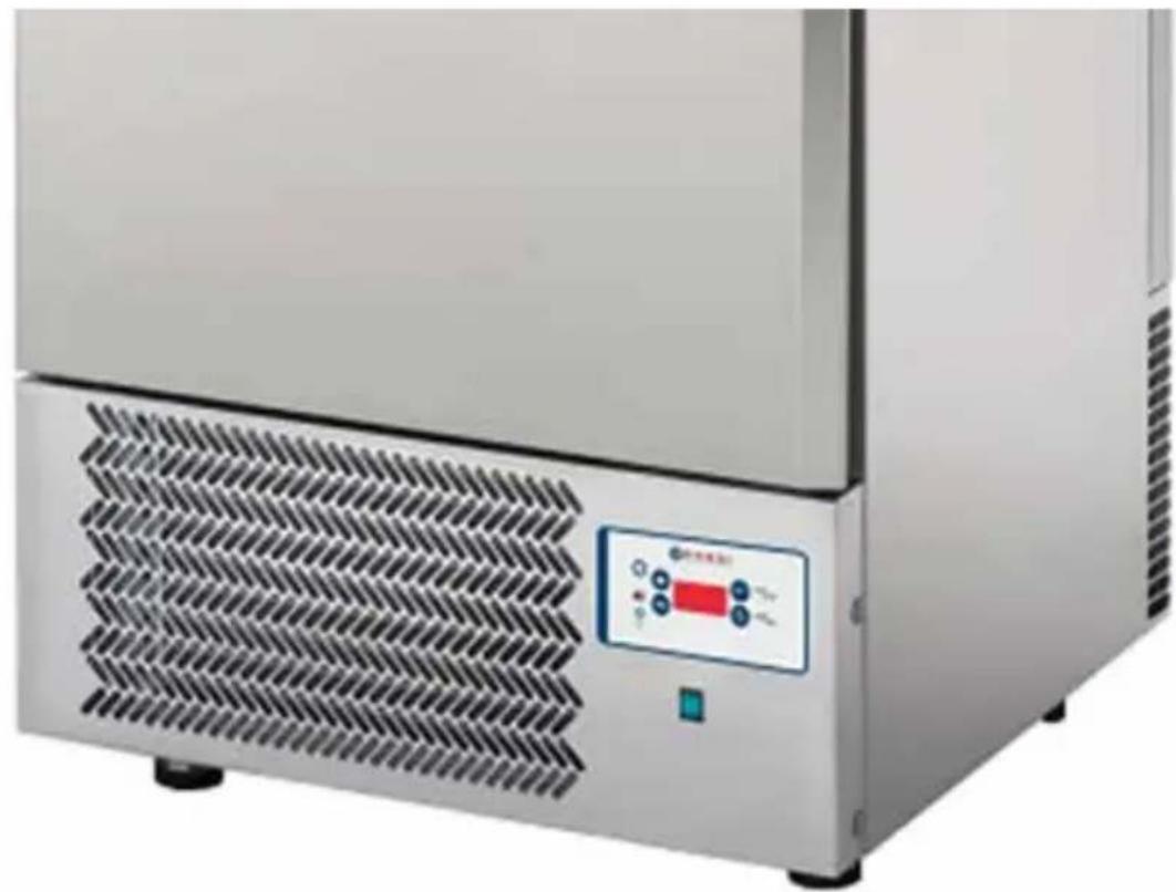
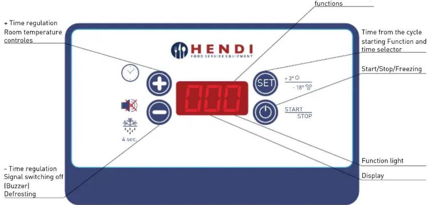
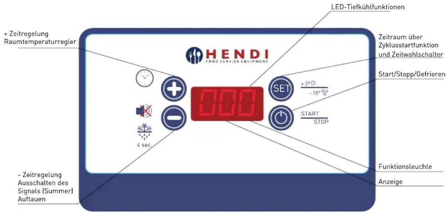
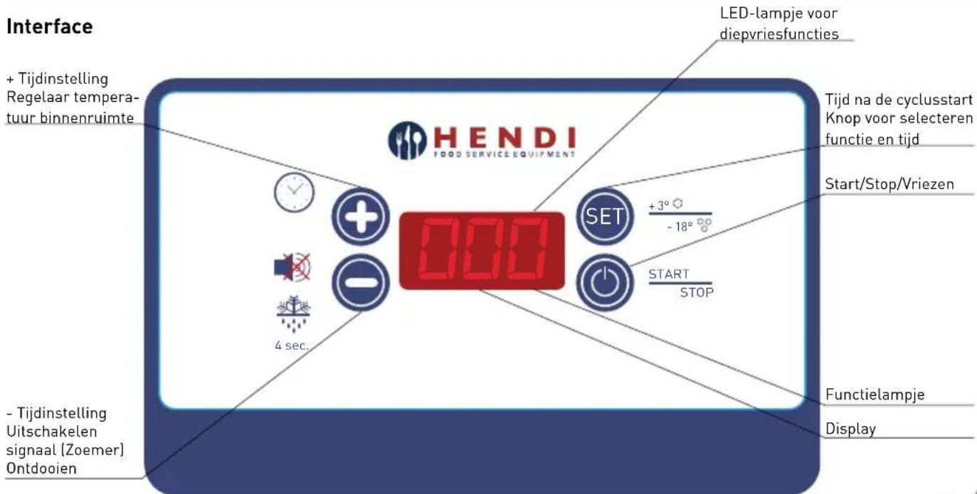
8. Control panel
Description
The control panels manages the basic functions of the device:
• Positive blast-freezing or cooling
- Negative blast-freezing or deep-freezing
• Hearth probe or time blast-freezing
- Conservation
- Manual defrosting without heater or hot gas
Thanks to some parameters is possible to erase some functions or change others.
The final user (the cook) can select the type of cycle and the chilling time when the core probe is not selected.
natural_image
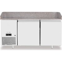
Exterior view of a stainless steel industrial kitchen unit with ventilation grille and control panel (no visible text or symbols)Interface
There is a 5 seconds lamp-test when the control stats, after that it places in Operative position.
Keys
The front panel stops in stand by functions if the button "SET" Ⓜ is pressing for 4 seconds when the
blasting cycles have been stopped.
Time and core probe program setting
| PROGRAMA PROGRAM | PULSANTE KEY | DISPLAY | PULSANTE KEY | DISPLAY | PULSANTE KEY | PARTENZA CICLO CYCLE START | FINE CICLO CYCLE STOP | MANTENIMENTO KEEPING | SBRINAMENTO DEFROSTING |
| +3° | BUZZER | ||||||||
| -18° | |||||||||
| +3° | BUZZER | ||||||||
| -18° |
Stop - Display
When the time cycle is selected the display shows the time (in hours and minutes) or the records of the core probe if the probe cycle is selected.
The upper point of the second display shows the selection in case of negative process.
Stop - Keys
- Set Ⓗ, Up ⏻ Down keys permit to enter the cycle setting.
- Set SET to go automatically to the negative and positive probe cycle process.
- Press Set SET key for 4 sec the control panel is in stand-by.
Start - Display
The display shows the remaining time (in hours and minutes), when the time cycle is selected or the records of the core probe if the probe cycle is selected.
Start - Keys
- Pressing the "SET" set key the display shows the time passed from the starting of the cycle or the time of the time cycle, in order to reach the cycle temperature, if it is in conservation modality.
- Press Up or Down to set automatically time cycle if previously was selected the core probe cycle, otherwise set +/- for the time cycle.
- If the buzzer is on, pressing Down to turn it off.
- Press Start/Stop to start the cycle.
If the presence of door is on (PI=1) and the contact is not well closed, on the display appears "dr" which shows that the door is open.
- Pressing Up, the temperature recorded by the room probe is shown. This data lasts 5 seconds.
- If the buzzer is on, pressing Down to turn it off.
- Press Start/Stop to start the cycle.

ATTENTION!
At the end of the positive process phase, the conservation program is set automatically at the temperature of 0 to +3°C.
At the end of the negative process phase, the con-
Alarms
The existing alarms are those related to the probes. They are shown only when it is required the view of the relative probe. "Er" Generic or internal error of the probes.
"Er" generic error or inside the probe
"Erl" room probe error
"Er2" core probe error
Regulations
Compressor
The compressor can be active only in START function when the room probe has no error.
If the presence of door is on (PI=1), the door must be closed to permit the starting of the compressor only if P6=0. With P6=0 the compressor is active even if the door is open and with arrested fan. The compressor starts according to the SET POINT on, corresponding to the selected cycle and according to the differential of temperature set (Parameter P8).
Manual defrosting
servation program is set automatically at the temperature of -22 to -25^ C.
In order to respect the chilling and freezing time provided by law, while a cycle is in progress, it is strongly advised against opening the door of the device.
If one program is in progress and an error is generated, the cycle passes to time process even if the error continues to be on.
The protection time for the compressor are:
- P9: minimum delay that must exist between the switching off and the next starting up of the compressor. This parameter is used also like reset of the card.
- P10: minimum delay that must exist between 2 consecutive starting ups of the compressor.
The defrosting is carried out with open door, without the use of neither the heater nor the hot gas.
Parameters
Pressing contemporarily Up and Down to enter the parameter setting for at least 4 sec.
At this point on the display appears the number itself of the parameter (P0). Pressing the SET key, it is possible to see the value of the parameter itself and modify it.
The keys Up and Down, when the parameter setting is on, allow to pass to the next/former parameter; when the value of the parameter is on, they modify it.
Description Min Max Def. Unit
| 0 Permit to enter into the conservation function: the buzzer rings for 60 sec. 0 1 1 - | |||||
| 1 Door present 0=door absent; 1=door present 0 1 1 - | |||||
| 2 Fan during he process 0=together with the compressor; 1=always on 0 1 1 - | |||||
| 3 Permit to enter the core probe function 0 1 1 - | |||||
| 4 Permit to enter the negative process 0 1 1 - | |||||
| 5 Permit to enter the defrosting 0 1 0 - | |||||
| 6 | Stopping functions when the door is open 0=compressor+fans; 1=fans | 0 | 1 | 1 | - |
| 7 Configuration RL2=defrosting; 1=fan+defrosting | 0 1 1 - | ||||
| 8 | Hystresis of regulation | 0 | 20 | 3 | °C |
| 9 | Protection of the compressor Off/On (also valid as reset) | 0 | 99 | 2 | min |
| 10 | Protection of the compressor Off/On | 0 | 99 | 3 | min |
| 11 | Defrosting duration | 0 | 99 | 10 | min |
| 12 | Dripping duration | 0 | 99 | 3 | min |
| 13 | Core probe for the positive process | -50 | 99 | 3 | °C |
| 14 | Core probe for the negative process | -50 | 99 | -18 | °C |
| 15 | Room probe for the positive process | -50 | 99 | -2 | °C |
| 16 | Room probe for the negative process | -50 | 99 | -40 | °C |
| 17 | Room probe for the positive conservation process | -50 | 99 | 0 | °C |
| 18 | Room probe for the negative conservation process | -50 | 99 | -25 | °C |
| 19 | Postive time process duration | 0 | 599 | 90 | min |
| 20 | Negative time process duration | 0 | 599 | 270 | min |
| 21 | Set condenser temperature for second fan | 60 | -50 | 99 | °C |
| 22 | Enable controller for secondary fan | 1 | 0 | 1 | - |
9. Maintenance – disposal of materials
All maintenance operations and reparations of the appliance must be carried out with stationary unit, removing the tension from both the refrigerated item and the condensing unit. All the operations must be carried out by qualified and specialized staff.
Periodical checks
At regular intervals (at least once a year), it is important to make a complete system check by qualified staff only. Please check that:
- the water drainage system works properly.
- there are no refrigerating gas leaks and the complete refrigerating system works properly.

ATTENTION!
All cleaning ordinary and extraordinary operation are described in chapter "CLEANING".
- the maintenance state of the electrical system is completely safe.
- the door gaskets and the door itself close properly.
- the condenser of refrigerating unit is clean.
If the device is provided with a fan motor and it is necessary to remove it, it is important to taking off the tension, verify the label with technical data of
Substitution of the compressor / refrigerated gas
In case of compressor damaging and/or replacing, save its refrigerating gas and oil and avoid disper-
Requesting spare parts
When requesting spare parts, please say clearly:
- Model of the item
- Serial number of the item
the fan motor and substitute it with one of identical power, voltage and frequency.
sing it in the environment.
• Quantity of the spare part
Possibly, enclose also a picture of the part to be ordered.
10. Maintenance – disposal of materials
Message Breakdown malfunction Error Solutions
| ER | Ensure that all the cables are included in the terminal | Generic error or/ internal error of the probe | If the cable is tore off. insere it again and screw it up |
| ER1 | Ensure that all the cables are included in the terminal | Error of the room probe | If the cable is tore off. insere it again and screw it up |
| ER2 | Ensure that all the cables are included in the terminal | Error of the room probe | If the cable is tore off. insere it again and screw it up |
| Blasting time too long | Check if the evaporator is blocked with ice | Leave the door open for at least 15 min to melt the ice | |
| Check if the product is loaded correctly and does not exceed | Lighten the load of trays and grills | ||
| Check if the internatl fan is spinning | Contact rhe assisatnce | ||
| Ensure that the laboratory temperature is not too high and with high percentage of humidity | Contact rhe assisatnce | ||
| Failed conservation of the food at he end of the blasting cycle | Contact rhe assisatnce | ||
| ER2 | Ensure that all the cables are included in the terminal | Error of the room probe | If the cable is tore off. insere it again and screw it up |
| DR | The door is open The door is open | Check that the door is properly closed |
11. Warranty
Any defect affecting the functionality of the appliance which becomes apparent within one year after purchase will be repaired by free repair or replacement provided the appliance has been used and maintained in accordance with the instructions and has not been abused or misused in any way. Your statutory rights are not affected. If the appliance is claimed under warranty, state where and when it was purchased and include proof of purchase (e.g. receipt).
In line with our policy of continuous product development we reserve the right to change the product, packaging and documentation specifications without notice.
12. Discarding & Environment
When decommissioning the appliance, the product must not be disposed of with other household waste. Instead, it is your responsibility to dispose to your waste equipment by handing it over to a designated collection point. Failure to follow this rule may be penalized in accordance with applicable regulations on waste disposal. The separate collection and recycling of your waste equipment at the time of disposal will help conserve natural resources and ensure that it is recycled in a manner that protects human health and the environment. For more information about where you can drop off your waste for recycling, please contact your local waste collection company. The manufacturers and importers do not take responsibility for recycling, treatment and ecological disposal, either directly or through a public system.
natural_image
Simple circular diagram with arrows and a horizontal line, no text or symbols presentnatural_image
Technical line drawing of a rectangular enclosure with a spring and side panel, mounted on a brick wall (no text or symbols)natural_image
Simple line drawing of a hand holding a tool or tool, no text or symbols presentnatural_image
Exterior view of a stainless steel industrial kitchen unit with ventilation grille and control panel (no visible text or symbols)Schnittstelle
- Model of the item
- Serial number of the item

ATTENTION!
All cleaning ordinary and extraordinary operation are described in chapter "CLEANING".
- Quantity of the spare part Possibly, enclose also a picture of the part to be ordered.
natural_image
Technical line drawing of a rectangular enclosure with a spring and wall-mounted base, no text or symbols presentnatural_image
Simple line drawing of a hand holding a tool or tool, no text or symbols presentnatural_image
Exterior view of a modern stainless steel kitchen appliance with ventilation grille and control panel (no visible text or symbols)NL
Melding Defect storing Fout Oplossing
natural_image
Simple circular diagram with a horizontal line, a vertical line, and directional arrows indicating motion or movement (no text or symbols)natural_image
Simple line drawing of a hand holding a tool or tool, no text or symbols presentnatural_image
Exterior view of a modern stainless steel kitchen appliance with ventilation grille and control panel (no visible text or symbols)Interfejs
natural_image
Simple circular diagram with arrows and symbols, no readable text or labelsnatural_image
Simple line drawing of a hand holding a tool or tool, no text or symbols presentnatural_image
Exterior view of a stainless steel industrial appliance with ventilation grille and control panel (no visible text or symbols)Interface
natural_image
Simple circular diagram with arrows and curved lines, no text or symbols presentnatural_image
Simple line drawing of a hand holding a tool or tool, no text or symbols presentnatural_image
Exterior view of a stainless steel industrial appliance with ventilation grille and control panel (no visible text or symbols)interfaccia
natural_image
Simple circular diagram with a horizontal line, a curved arrow, and a vertical arrow inside, no text or symbols present.natural_image
Simple line drawing of a hand holding a tool or tool with a curved handle (no text or symbols)ATENTIE!
natural_image
Exterior view of a stainless steel industrial kitchen unit with ventilation grille and control panel (no visible text or symbols)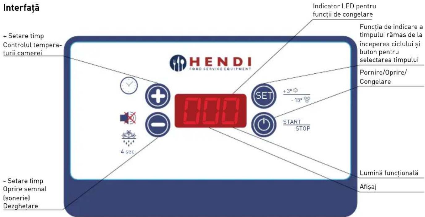
natural_image
Simple circular diagram with a horizontal line, arrows, and a circular outline, no text or symbols present.natural_image
Technical line drawing of a rectangular enclosure with a spring and side supports, mounted on a brick wall (no text or symbols)natural_image
Simple line drawing of a hand holding a tool or tool, no text or symbols present
ВНИМАНИЕ!
natural_image
Exterior view of a modern stainless steel industrial appliance with ventilation grille and control panel (no visible text or symbols)Интерфейс
Функции светодиода
natural_image
Simple circular diagram with arrows and symbols, no readable text or labelsnatural_image
Technical line drawing of a rectangular enclosure with a spring and wall-mounted base, no text or symbols presentnatural_image
Simple line drawing of a hand holding a tool or tool, no text or symbols present⚠️ ΠΡΟΣΟΧΗ!
natural_image
Exterior view of a stainless steel industrial appliance with ventilation grille and control panel (no visible text or symbols)Διεπαφή
62-023 Gądki, Poland
Tel: +48 61 6587000
Email: info@hendi.pl
Hendi Food Service Equipment GmbH
Central Barn, Hornby Road
Lancaster, LA2 9JX, United Kingdom
Tel: +44 (0)333 0143200
Email: sales@hendi.co.uk
Hendi Food Service Equipment Romania Srl
PKS Hendi South East Europe SA
5 Metsovou Str.
18346 Moschato, Athens, Greece
Tel: +30 210 4839700
Email: office.greece@hendi.eu
Hendi HK Ltd.
1208, 12/F Exchange Tower
33 Wang Chiu Road, Kowloon Bay, Hong Kong
Tel: +852 2154 2618
Email: info-hk@hendi.eu
Find Hendi on internet:
www.hendi.eu
www.facebook.com/HendiFoodServiceEquipment
www.linkedin.com/company/hendi-food-service-equipment-b.v.
www.youtube.com/HendiEquipment
- Changes, printing and typesetting errors reserved.
- Änderungen und Druckfehler vorbehalten.
- Wijzigingen en drukfouten voorbehouden.
- Producent zastrzega sobie prawo do zmian oraz błędów drukarskich w instrukcji.
-
Variations et fautes d'impression réservés.
-
Errori di cambiamenti, di stampa e di impaginazione riservati.
- Drepturi rezervate cu privire la modificări și greșeli de imprimare.
- Изменения, печати и верстки ошибки защищены.
- Με επιφύλαξη αλλαγών, λαθών εκτύπωσης και στοιχειοθεσίας.