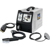
Combiduction Auto 50 LG - Cooker GYS - Free user manual and instructions
Find the device manual for free Combiduction Auto 50 LG GYS in PDF.

| Product Type | Induction heating for bodywork (portable) |
| Brand | GYS |
| Model | Combiduction Auto 50 LG |
| Power Supply | Single-phase 230 V ~, 50/60 Hz, 25 A |
| Input Power | 5 200 W |
| Output Power | 2 600 W |
| Weight | 70 kg |
| Dimensions (L x H x D) | 60 x 88 x 60 cm |
| Power Cable Length | 8 m |
| Lance Length | 3 m |
| Cooling Tank Capacity | 7 liters |
| Cooling Liquid | GYS special welding coolant (ref. 052246) |
| Protection Rating | IP21 |
| Operating Temperature Range | -10 to +40 °C |
| Processing Frequency | 20-60 kHz (microprocessor-controlled) |
| Operating Modes | Automatic, Manual, Timer, Forced Cooling |
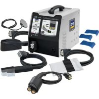
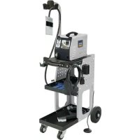
| Included Accessories | Inductors (glass, adhesives, spirals, dent removal), pneumatic pedal, keys |
| Safety | Thermal protection, automatic shutdown after inactivity, locking, E-code alarms |
| Maintenance | Annual coolant drain, cleaning with dry cloth, professional maintenance |
| Warranty | 2 years (parts and labor, excluding consumables) |
Frequently Asked Questions - Combiduction Auto 50 LG GYS
User questions about Combiduction Auto 50 LG GYS
0 question about this device. Answer the ones you know or ask your own.
Ask a new question about this device
Download the instructions for your Cooker in PDF format for free! Find your manual Combiduction Auto 50 LG - GYS and take your electronic device back in hand. On this page are published all the documents necessary for the use of your device. Combiduction Auto 50 LG by GYS.
USER MANUAL Combiduction Auto 50 LG GYS
natural_image
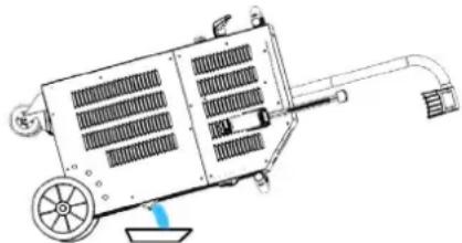
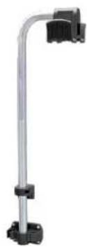
Line drawing of a portable industrial machine with wheels and control panel (no text or symbols)| FR | 02-22 / 119-122 |
| EN | 23-37 / 119-122 |
| DE | 38-53 / 119-122 |
| ES | 54-69 / 119-122 |
| RU | 70-85 / 119-122 |
| NL | 86-102 / 119-122 |
| IT | 103-118 / 119-122 |
COMBIDUCTION AUTO 50 LG
ASSEMBLAGE / ASSEMBLY / MONTAGE / ENSAMBLAJE / CBOPKA / MONTAGE / ASSEMBLAGGIO
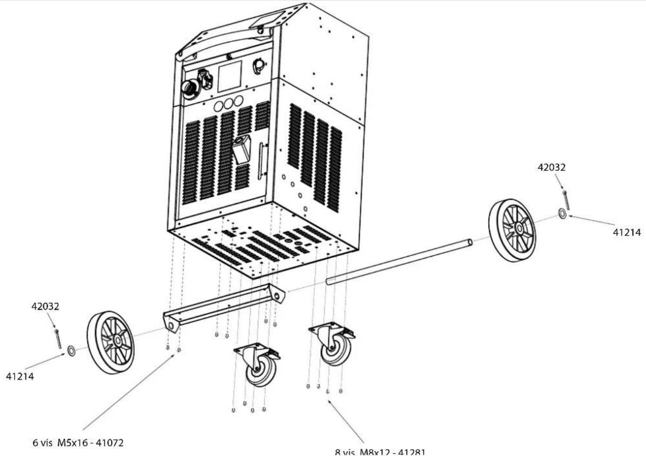
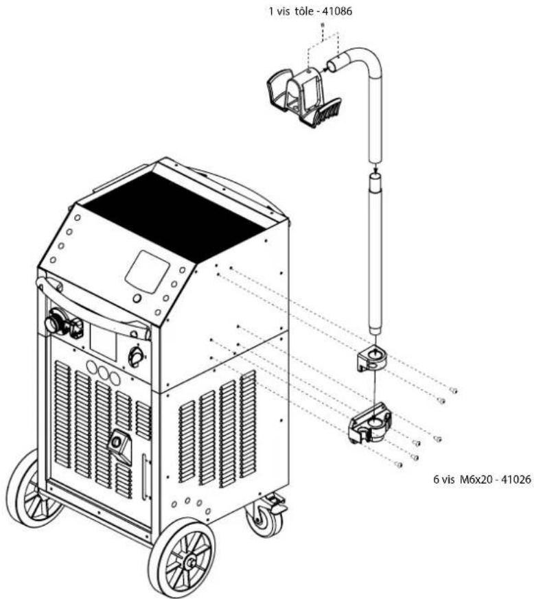
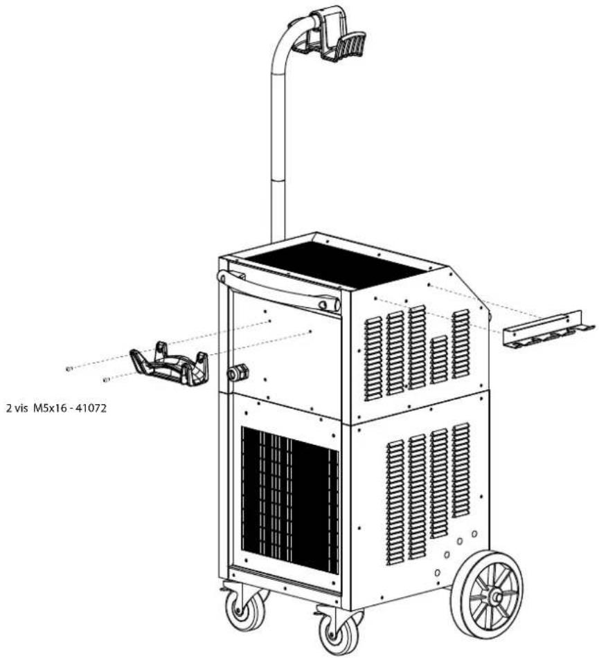
FR
natural_image
Line drawing of a dual-wheeled industrial machine with wheels and control panel (no text or symbols)|
||
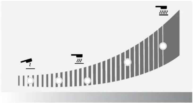
Réaction des témoins lumineux / Reaction of the indicator lights / Reaktion der Kontrollleuchten / Reacción de las luces indicadoras / Peakция индикаторных ламп / Reactie van de indicatielampjes / Reazione delle spie luminose
natural_image
Diagram showing a curved surface with vertical stripes and circular markers, no text or symbols present| État du voyant / Indicator status / Indikatorstatus / Estado del indicador / Состояние индикатора / Indicatorstatus / Stato dell'Indicatore | |
| Allumé / Light on / Licht an / Luz encendida / Освещать / Oplichten / Luce accesa | |
| Clignote lentement / Flashing slowly / Blinkt langsam / Parpadea lentamente / Мигания медленно / Knippert langzaam / Lampeggia lentamente | |
| Clignote rapidement / Flashing quickly / Blinkt schnell / Parpadea rápidamente / Мгновенно вспыхивает / knip-pert snel / Lampeggia rapidamente | |
| Éteint / Off / Aus / Apagado / Выключен / Uit / Spento | |
SPÉCIFICATIONS DU PRODUIT
natural_image
Four different types of electrical connectors shown in black, white, and gray, with no visible text or symbols.natural_image
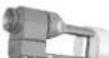
Close-up of a black cylindrical electronic component with a metallic tip and circular button, no visible text or symbols.Couple de serrage max = 7 Nm
natural_image
Close-up of a mechanical lever assembly with a handle and mounting bracket (no visible text or symbols)Découvrez la gamme complète |  | S180/B1Ref. 064881 |  | S180/B2Ref. 064928 |  | L180ref. 059795 |  | L20 ALU GLOVERef. 069114 |
 | S180/B3 WRef. 067899 |  | S180 D20Ref. 069985S180 D25Ref. 069992S180 D30Ref. 070592 |  | L180 D60Ref. 069923L180 D70Ref. 069930L180 D80Ref. 069121 |  | L180 D90Ref. 069947L180 D100Ref. 069954L180 D110Ref. 069961 | |
 | S180 D35Ref. 070608S180 D40Ref. 070615S180 D45Ref. 070622 |  | S180 D50Ref. 070639S180 D55Ref. 070646 |  | L180 D120Ref. 069978 |
DESCRIPTION & UTILISATION DES INDUCTEURS

natural_image
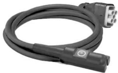
Coiled black cable with a connector, no visible text or symbols
Description
natural_image
Diagram of a car interior showing airflow or movement around a vehicle handle (no text or symbols)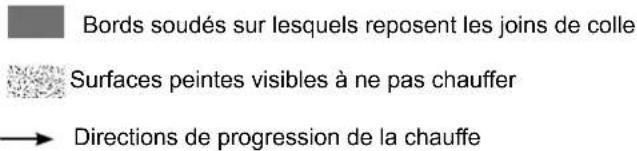
natural_image
Diagram of a car interior showing airflow or airflow direction with arrows indicating movement (no text or symbols)natural_image
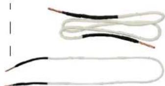
Coiled black cable with a white bandage, next to a small electronic component (no text or symbols visible)
Description
natural_image
Line drawing of a printer with a cover and paper strip, no text or symbols presentnatural_image
Coiled black cable with two connectors, no visible text or symbols
Description
natural_image
Coiled black electrical plug with two connectors (no text or symbols visible)
Description
natural_image
Technical line drawing of a mechanical device with fan, wheels, and attached cable (no text or symbols)natural_image
Open black medical or laboratory equipment case with coiled wires and a tool, no visible text or symbolsnatural_image
Metallic stand with attached black connectors (no text or symbols visible)
Protection ferrite B1
Réf. 056909

Protection ferrite B2
Réf. 056916

Protection ferrite B4
Réf. 054844

Cloche
CONDITIONS DE GARANTIE
This user's manual includes operating instructions and safety precautions for your device.
Please read it carefully before first use and keep it for future reference.
These instructions must be read and fully understood before use.
Do not undertake any alterations or maintenance work that is not directly specified in this manual.
The manufacturer shall not be liable for any damage to persons or property resulting from use not in accordance with the instructions in this manual.
If you have any problems or queries, please consult a qualified person to correctly operate the equipment.
This appliance must only be used for heating ferrous materials within the limits indicated on the appliance and in the user manual. The safety instructions must be followed. The manufacturer cannot be held responsible in the event of improper or dangerous use.
ENVIRONMENT
Temperature range:
Use between -10 and +40°C (+14 and +104°F).
Store between -25 and +55°C (-13 and 131°F).
Air humidity:
Lower than or equal to 50% at 40°C (104°F).
Lower than or equal to 90% at 20°C (68°F).
Altitude:
Up to 1,000 m above sea level (3280 feet).
PROTECTING YOURSELF AND OTHERS
Induction heating can be dangerous and can cause serious injury or death.
Induction heating exposes people to a potentially dangerous heat source, electromagnetic fields and light radiation.
To protect yourself and others, please observe the following safety instructions:

- To protect yourself from optical radiation, as well as metal spatter, wear a mask or shade-five goggles.

- To protect yourself from burns and radiation, wear warm, dry, cuffless clothing that is fireproof, in good condition and that covers the whole body.
- Do not wear clothing with metal fasteners, metal buttons or metal covers of any kind.

- Use gloves that provide both electrical and thermal insulation.

- This machine is not suitable for use by those with pacemakers.
- Those using pacemakers should not come within one metre of the device when it is in use.
- There is a risk of disturbing the proper functioning of pacemakers when in close proximity to the machine.

- This machine is not suitable for use by those with metal implants.
- People with metal implants should not come within one metre of the device when it is in operation.

- Ensure that jewellery (especially wedding rings) or metal objects (keys, watches, etc.) do not come close to the induction system and the inductor when in operation.
- Remove all jewellery and other metal objects from your person before using this equipment.
RISK OF BURNS

- Induction heating very rapidly increases the temperature of the metal!
- Do not touch hot parts of the machine or the inductor with bare hands.
- Wait for parts and equipment to cool before handling them.
• In the event of burns, rinse with plenty of water and seek medical attention immediately.
RISK OF FIRES AND EXPLOSIONS

- Do not place the appliance on, or near, flammable surfaces.
- Do not install the device near flammable or combustible substances.

- Do not heat containers, vessels or pipes that contain or have contained flammable liquids or gases.
- Do not overheat parts or adhesives.
- In the event of a fire, use a fire extinguisher or fire blanket.

- Do not use this equipment in an explosive atmosphere.

- Do not heat pressure vessels.

- Keep airbags, aerosol cans and other pressurised containers away from induction-heating equipment.

- Keep your head well clear of the fumes, do not breathe the fumes.
- When working indoors, ventilate the area and/or use an air extractor to clear fumes and gases.
- Induction heating certain materials, adhesives and fluxes can produce fumes and gases. Breathing these fumes and gases can be hazardous to your health. For example, heating urethane releases a gas: hydrogen cyanide, which can be fatal to people.
- If ventilation is poor, use an approved welding-fume extractor.
- Read the Material Safety Data Sheets (MSDS) and manufacturer's instructions for adhesives, fluxes, metals, consumables, coatings, cleaning agents, and paint strippers.
- Only work in a confined space if it is well ventilated or if using an approved welding-fume extractor. Make sure you have a qualified person monitoring you. The vapours and gases produced when heating can replace the oxygen in the air causing accidents or death. Make sure the air you breathe is clean.
- Do not use the heater on parts that are being degreased or sprayed. Heat can react with vapours to form highly toxic and irritant gases.
- Do not overheat metals, such as lead- or cadmium-coated, galvanized steel, unless the coating is removed from the surface to be heated, the work area is well ventilated and, if necessary, using an approved welding-fume extractor. Foundry pieces, as well as all metals containing these elements, can release toxic fumes if overheated.
Refer to the MSDS (Material Safety Data Sheets) for temperature-related information.
ELECTROMAGNETIC RADIATION

- During operation, the inductor will generate strong, invisible electromagnetic fields.
- This equipment has been designed to minimise the risks from electromagnetic fields, however, there still remains some risk.
- Keep a minimum safety distance of 30~cm between the inductor machine and the operator's head and body.
- The inductor must be aimed only at the metal parts to be heated.
- Never wrap the lance around the body.
OPTICAL RADIATION

- There is a risk of optical radiation when heated metal elements approach and reach melting point.
- Optical radiation can be harmful to the eyes and skin.
ELECTRICAL HAZARD

An electric shock can be the source of a serious accident, whether directly or indirectly, or even death.

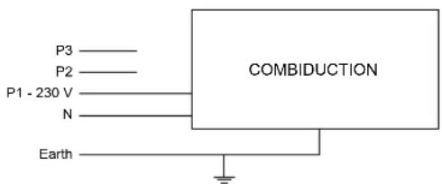
This is a Class I appliance, to be used only with a single-phase, 230 V (50/60 Hz), three-wire electrical installation with an earthed connection.
- The maximum absorbed current (I1) is shown on the equipment to ensure optimum operating conditions. Check that the power supply and its safeguards (fuses and/or circuit breakers) are all compatible with the electric current being used.
- The earthing lead must not be broken or disconnected (e.g. by an extension cord).
- Do not use the appliance if the power cable, the mains plug or the lance is damaged.
- Do not use the inductor in the rain, on wet parts or on component pieces that are under water.
EMC CLASSIFICATION

- This equipment is intended for use in industrial environments (Class A or Group 2) and is not intended for use in a residential setting where power is supplied from the public, low-voltage supply network. Ensuring electromagnetic compatibility may be difficult at these sites due to conducted, as well as radiated, radio frequency interference.
- This equipment complies with standard IEC 61000-3-12.
• This equipment complies with standard IEC 61000-3-11.
MAINTENANCE / RECOMMENDATIONS

- Maintenance should only be carried out by a qualified person. Annual maintenance is recommended.
- Warning! Always disconnect from the mains before carrying out maintenance on this machine. Voltages and currents are high and dangerous inside the machine.
- Remove the cover and blow out the dust. Take the opportunity to have the earthing and electrical connections checked with an insulated tool.
- Do not use solvents or any agressive cleaning products.
- Clean the device's surfaces with a dry cloth.
- If the power cable or lance is damaged, it must be replaced by the manufacturer, the service department or a similarly qualified person in order to avoid a safety hazard.
- If the internal fuse has blown, it must be replaced by the manufacturer, the service department or a similarly qualified person in order to avoid a safety hazard.
- Do not block the vents. Refer to the installation instructions before using the appliance.
- Keep at least 50 cm of free space around the equipment.
TRANSPORT
- Do not use the power cable or lance to move the unit. It should be moved in an upright position.
- The handles are not designed to be used to lift the device.
RULES AND REGULATIONS

- This device complies with European directives.
- The declaration of conformity is available on our website (see cover page).
- This equipment conforms to UK requirements.
- The UK Declaration of Conformity is also available on our website (see cover page).

- This device complies with Moroccan standards.
- The C_ (CMIM) declaration of conformity is available on our website.


• The Eurasian Economic Community (EAEC) mark of conformity.
WASTE DISPOSAL

- This equipment is subject to selective collection. Do not dispose of in domestic waste.

- This is a recyclable product that is subject to recycling instructions.
PRODUCT IDENTIFICATION
The machine's CE marking can be found on the back of the product on an identification plate, along with the following:
- Manufacturer's name and address
- Manufacturing date
- Model
- Product type
- Operating voltage
This data must be given every time a technician is called in or if spare parts are needed.
PRODUCT SPECIFICATIONS
| COMBIDUCTION | |
| Input-voltage rating 230 V ~ | |
| Assigned frequency 50 Hz - 60 Hz | |
| Number of conductors One phase, one earth and one neutral. | |
| Input-current rating 25 A | |
| Input-power rating 5,200 W | |
| Treatment frequency 20-60 kHz, controlled by microprocessor. | |
| Output-power rating 2,600 W | |
| Power cable length 8 m | |
| Lance length 3 m | |
| Tank capacity 7 litres | |
| Coolant | Special welding coolant,10 litres (ref. 052246) |
| Protection rating IP 21 | |
| Min. dimensions power generating unit | 6,5 kVA |
| Weight (kg) 70 | |
| Dimensions (cm) 60 x 88 x 60 cm | |
| Internal fuse T4 A - 250 VAC - 5x20 | |
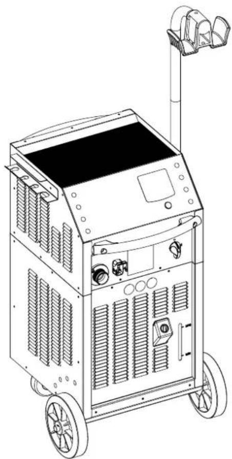
DETAILED DESCRIPTION (FIG I)
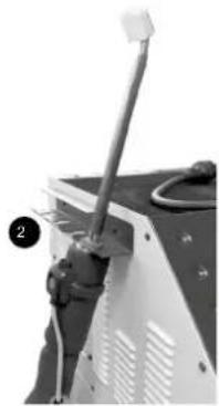
| 1 | Main switch |
| 2 | Illuminated power button |
| 3 | Connector for bodywork accessories |
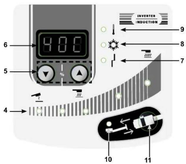
| 4 | Heating capacity indicators (1 kW - 5 kW) |
| 5 | Buttons for setting the heating power or choosing the temperature display unit |
| 6 | Coolant temperature and setpoint |
| 7 | Power-source or inductor-fault warning light |
| 8 | Cooling system warning light |
| 9 | The power source's or cooling system's thermal-protection warning light |
| 10 | Inductor-change mode warning light |
| 11 | Inductor-change mode activation button |
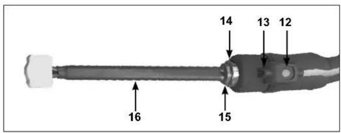
| 12 | Lance button: triggers heating |
| 13 | The heating point's LED lighting |
| 14 | Lance attachment. For a 32 mm spanner |
| 15 | For a 27 mm spanner |
| 16 | Complete inductor |
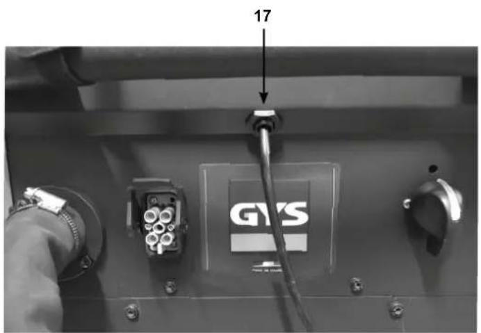
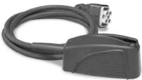
| 17 | Foot pedal connector |
| 18 | Pneumatic foot pedal |
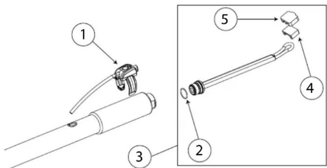
FIRST USE
The COMBIDUCTION comes with an eight metre power cord complete with a five-pin 32 A 50/60 Hz power socket. To ensure this product's optimum performance, it must be plugged into an electrical outlet with 32 A protection and be protected in accordance with current standards. The machine is supplied with a 32 A - 16 A adapter. It allows the power source to be used on a 16 A socket in accordance with short-term work standards, mainly for removing nuts. To operate without activating the mains protection, set the power to 3.5 kW 70% (see connection instructions).
- Once the product has been assembled, position the lance on its support. Remove the cap from the lance and the tank.
- Fill the tank to the maximum with the special welding coolant.
- Take the lance and place it over a bucket or an empty jerry can.
- Connect the product to the mains network. Flip the main switch (1) to the ON position.
- The product will start and repeatedly show Error 7 («E-7»).
- Press the inductor change button (11) twice. The purge cycle takes five seconds and is indicated by a loading sign shown on the display screen. A double beep indicates the end of the cycle.
-
As soon as the liquid comes out of the lance, stop the flow by pressing the lance button (12) or wait for the display message «E-6». If the display shows «E-7», repeat the process from step six (a maximum of five times, otherwise refer to the «E-7 Fault Correction» section).
-
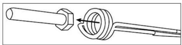
Tighten the inductor with a maximum torque of 7 Nm.
- Press the inductor change button (11) twice. The purge cycle takes five seconds and is indicated by a loading sign shown on the display screen. A double beep indicates the end of the cycle.
- The display screen will alternate between the coolant temperature and the power setpoint.
- Top up the coolant if necessary.
- Put the supplied tank cap in the accessory case. The product is ready for use.
E-7 fault correction
After five unsuccessful attempts at completing a purge cycle, the following procedure is to be undertaken:
- Stretch out the lance over the product, so that the water pockets drain away allowing the pump to prime.
- Tilt the product approximately 30^ towards the lance.
- It is now possible to blow into the end of the lance. Use a compressed-air blower with a cloth to seal the end of the lance and avoid splattering.
- Restart one or two cycles after each action.
If the problem persists, then check that the pump is working properly or that the pipe is not pinched or blocked.
INSTRUCTIONS FOR USE
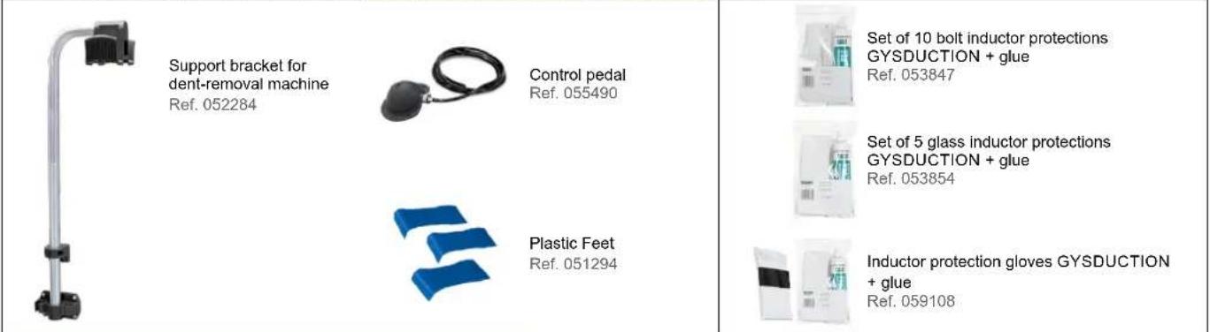
Connecting the foot pedal
The COMBIDUCTION is supplied with a foot pedal (ref. 055490), which is very practical and even necessary for the use of some inductors (adhesive inductors). Connect the hose to the COMBIDUCTION and to the foot pedal to make it operational.
- Flip the main switch (1) to the ON position.
The machine carries out its start-up phase for two seconds.
This product has two heating options: the first using the lance or the second using the bodywork inductors. It always starts up when the power is turned on and heats up through the lance.
Lance heating
- Press the main power button (2). The indicator light for button two and the LED indicator light for the inductor (13) will light up, signalling that the product is ready for heating.
- Position the inductor (16) flat on the workpiece or the part to be heated (place the open part of the ferrite against the workpiece).
- Press button (12) on the lance or on the foot pedal (18) to start heating; if necessary move the inductor to heat a larger area. Two indicator lights show that the heater is active:
- The brightness of the inductor's LED indicator light (13) will decrease*.
- The minimum-power indicator light on the heating power indicator (4) will flash rapidly (in HI mode both minimum and maximum indicator lights will flash).
It is possible to change the power setpoint while heating.
 | The heating setpoint can be set to the value Hi. The power is the same as the 100% mode but the COMBI-DUCTION will behave differently:- At 100%: it turns the workpiece red and keeps it at the right power for a few seconds before slowly achieving its maximum power.- In Hi mode: it will climb to its maximum power regardless of the condition of the workpiece to be heated.Be very careful, the heating process is strong, fast and may damage the workpiece. |
The display continuously shows the coolant temperature (max. 60°C/140°F).
- During the initialisation phase, the cooling system's pump and fan will run for a few seconds to check that it is working properly.
- After stopping the heating process, allow the cooling system to fully cool the inductor before switching off the product.
- To change the unit used to display the coolant's temperature, press and hold both setting buttons (5) until the desired unit is selected («-F-» = Fahrenheit / «-C-» = Celsius). When you release the buttons, this change is saved and displayed.

The machine has been designed to minimise the risks caused by electromagnetic fields. There are still risks and it is recommended that a minimum safety distance of 30 cm is kept between the inductor and the operator's head or torso.
Putting the heater on standby mode
For safety reasons, the product disables all heating power after the power source has been inactive for five minutes. The green LED indicator light on the main power button (2) and the LED indicator light on the lance holder (13) will go out.
To restart the power source, press and hold the start button (12) for one second.
After being inactive for 20 minutes, the power source can only be reactivated by pushing the main power button (2).
Heating with bodywork inductors
Connecting attachments and accessories
- Select the desired inductor.
- Lift the lid to reach the COMBIDUCTION socket.
- Plug the inductor connector into the COMBIDUCTION.
- Close the lid to secure the connection.
- The display screen will show the number of connected accessories (e.g. AC1)
Heat activation
Press the main power button (2)
All inductors can be operated using the foot pedal. Glass, dent-removal and spiral inductors are also fitted with a heating button.
Bring the inductor close to the metal part that is to be heated, then press the inductor button or foot pedal to activate the heating process.
The power source will detect this and start up in automatic mode.
Automatic Mode In this mode, the COMBIDUCTION adapts to the workpiece it is heating
(size-thickness) and also to the distance between the workpiece and the inductor. It maintains a constant and optimal heating power. The heater will never heat up to full power in this mode.
To access this mode: Automatic mode is the default mode. However, if the machine is in Manual mode, press the inductor-change button (11) briefly until the dashes on the digital display (6) flash.
Display: The digital display shows the last % value used by the machine to maintain a constant, optimal output according to the heating requirements. This value corresponds to the settings that would have to be used in Manual mode to obtain the same result under the same conditions. Therefore, if the user considers the heating recommended by the COMBIDUCTION to be too low or too high, the user can set this value in manual mode and adjust it as desired to reach the required power.
Manual Mode In this mode, the user selects the desired heating power themsevles.
To access this mode: Press the change-inductor button (11) briefly until a numerical value is displayed.
How it works: The digital display screen (6) indicates the maximum power percentage (2,400 W) that the inductor can transmit to the workpiece to be heated. Use the adjustment dials (5) to change the desired power level.

Manual mode allows the COMBIDUCTION to reach its maximum power. At this power level, workpieces can be heated very quickly. The closer the inductor is to the workpiece, the greater the heating power.
Audible heating signals
A beeping sound can be switched on to indicate heating activity. The beep sounds as soon as the heating process is active and its frequency varies according to the position of the inductor in relation to the workpiece to be heated. The closer the inductor, the higher the frequency.
To activate / deactivate this feature:
Press the change-inductor button (11) for three seconds to activate/deactivate this sound.
Thermal-protection indicator (9)
This warning light lights up to indicate that the product has gone into thermal protection due to overheating. As long as this warning light remains on, the product is inoperative. It switches off when the product has sufficiently cooled down. Only then is it possible to resume heating.
CHANGING THE INDUCTOR TYPE
- To switch to the car body inductors, press and hold the glass/glove inductor button that has been plugged into the socket (3) on the unit. Alternatively, press and hold the pneumatic foot pedal (18) while the main power button is switched off. The COMBIDUCTION will then automatically register its presence and become fully functional.
- To be able to heat, whatever the inductor, press the illuminated main power button(2).
- Then, press the inductor button or the pneumatic foot pedal to start heating.
- To re-engage the lance, press the lance button (12).
Listen for a beep and a new display on the screen.
Press the main power button (2).
Then, press the lance button or pneumatic foot pedal to activate the heating process.
INDUCTOR PRESERVATION
The hot metal will radiate heat to the inductor at the square of the temperature to which it is heated. Thus, the inductor is highly exposed. Once the metal has turned dark red, the temperature is below 850^ C. If it turns bright red/orange, the temperature has exceeded 1,000^ C. If it turns white, the temperature has exceeded 1,200^ C (see the colour chart available below and on the website).
600 °C 900 °C 1,300 °C
To preserve the inductor and extend its working life, keep the temperature as low as possible (around 850^ C) and avoid prolonged use.
The ferrite in the inductor has a higher expansion coefficient than its mechanical support. Excessively heated the inductor may lead to ferrite damage. It is up to the user to avoid excessive heating.

Therefore, the warranty does not cover inductors as they are consumables.
WARNING LIGHTS
- The LED indicator light (7) highlights if there is a fault with the inductor or power source.
- Indicator light (8) signals a flow failure in the liquid cooling system.
- The LED indicator light (9) signals that the power block has gone into thermal protection or that the coolant's upper-limit temperature has been exceeded.
Once the indicator light has gone out, the product is ready for use again.
Display screen number five will show the fault code:
| Default code | Cause | |
| E - 1 Main | power button (2) not pressed. Short-circuited or mechanically blocked. | |
| E - 2 Lance | button not pressed (12). Short-circuited or mechanically blocked. | |
| E - 3 Press | and hold buttons (5) or (11). Short-circuited or mechanically blocked. | |
| E - 4* | Inductor current is too high or not compatible. | Defective lance or short-circuited inductor. |
| E - 5* Inductor current is too low | Poorly screwed-in inductor or defective lance. | |
| E - 6 Flow rate is too high >6 l/min | Hole in hose or no inductor. | |
| E - 7 Flow rate is too low <4 l/min | Pinched or clogged hose, pump does not work. | |
| E - 8* Internal fault | Control panel disconnected. | |
| E - 9 | Mains voltage fault | The mains voltage is too low at under 165 V. |
| --- | Over-voltage fault | Mains voltage above 300 V. |
| *In the case of faults E-4, E-5 and E-8, restart the unit to reset the fault. | ||
| Fault code E5Inductor screwing problem :(check screwing, be careful not to overtighten!) | Fault code E6Flow rate fault refer to pages 10, 11, 12, 16 | Fault code E7Flow rate fault refer to pages 10, 11, 12, 16 |
 |  |  |
NB: In the event of an alarm, the appliance will not heat up.
The device is equipped with several electronic protection systems for electrical overload and cooling. The inductor's thermal protection is particularly important when heating stainless steel, copper or aluminium parts. To restart, simply wait for the cooling process to end. For all other protections, switch the device off and on again using the main switch.
For E-6 and E-7 alarms, please check:
- if there is a possible leak.
- that the hose is not blocked or kinked.
- that the pump is not blocked or defective.
- there is enough coolant.
If the fault appears to be rectified, press the inductor change button (11) twice. The product will perform a purge cycle. It is now ready for use.
"TIMER" MODE\*
The "Timer" function allows you to control the COMBIDUCTION's heating time.
The time can be adjusted from 1 to 30 seconds.* (Time adjustable from 1 to 120 s from Soft V6.50 version)*.
To enter this mode:
- Press the main power button (2). Its indicator light will come on.
- Then, press both power-setting buttons (5) simultaneously.
- The display will show "SEC" then "T 00" or "SEC", then "ON" if a time has already been set.
- The power-setting buttons (5) become time-setting buttons. Change the time settings as required.
If, after three seconds, the time value has not been changed and still shows "T 00", the COMBIDUCTION will return to normal mode.
Using the "Timer" mode:
Once the time settings have been selected, the product is ready for use. The LED light (13) is on.
- Press the lance button (12). The intensity of the LED indicator light (13) will decrease signalling that the machine is actively heating up.
- The heating will stop when the time is finished. As long as the lance button (12) is pressed, the LED indicator light (13) and the main power button (2) will flash to advise that the power is switched off. Adjust the time settings if necessary.
- Press the lance button (12) to start a new heating cycle.
Leaving "Timer" mode
This mode always remains active, even when the COMBIDUCTION is switched off and on again.
- To exit this mode, set the time settings to or press the two power control buttons (5) simultaneously. The COMBI-DUCTION will return to its normal operating mode. The display will read “SEC” and then “OFF”.
This mode's special-feature power settings.
As explained, in normal use the control buttons are used to alter the power, whereas in this mode they are used to alter the time settings. How to change the power without leaving this mode:
- Press the main power button (2). Its green indicator light will go out.
- The setting buttons (5) are used to change the power. Adjusting the power.
- Press the main power button (2) again. Its indicator light will come back on. The setting buttons (5) will revert to controlling the time settings.
"ACCESSORY-CHANGE" MODE
flowchart
graph LR
    A["STOP"] --> B["A"]
    B --> C["B"]
    C --> D["OK"]
    style A fill:#f9f,stroke:#333
    style B fill:#ccf,stroke:#333
    style C fill:#cfc,stroke:#333
    style D fill:#fcc,stroke:#333
screen-printed product
natural_image
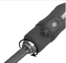
Close-up of a black mechanical component with a circular arrow indicating rotation (no visible text or symbols)Max. tightening torque = 7 Nm
- Press the inductor-change button (11), the pump will stop and the LED (10) will light up.
- Place the lance on its support, put the cable on the ground to avoid liquid loss.
- If the COMBIDUCTION is fitted with a complete inductor, unscrew it with the 27 mm spanner (supplied with the product). If it is equipped with a single inductor, unscrew it manually and then unscrew the adaptor if necessary.
- Depending on the choice of the new inductor: screw in a complete inductor using the spanner provided or screw in the appropriate adaptor (7 N.m max) and then the new inductor manually.
-
Press the inductor-change button (11) again.
-
The pump will run for five seconds. A loading sign will be displayed.
- If the flow rate is correct, a double beep will sound and the product is ready for use.
- Otherwise a fault will be displayed (refer to the fault code table).
natural_image
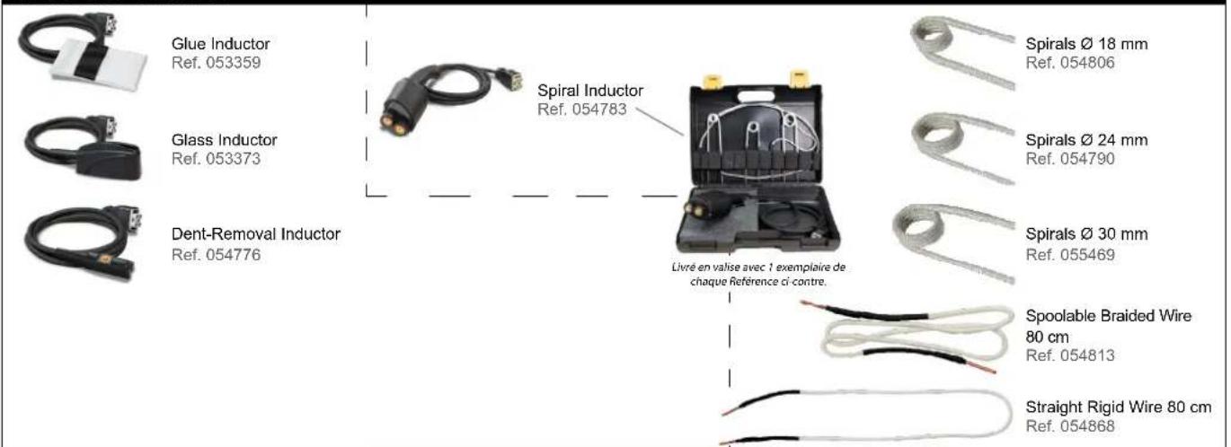
Close-up of a mechanical device with a lever and cable (no visible text or symbols)Inductors and Adapters
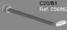
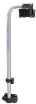
The COMBIDUCTION is supplied with the complete C20/B1 inductor as standard.
The other accessories are optional and can be used to broaden the range of heating options available for a variety of applications.
| Full Inductors Adaptors | ||||||
 | 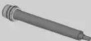 28SRef. 064485 28SRef. 064485 | 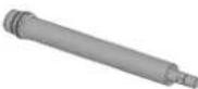  | ||||
 | Inductors | |||||
 S90Ref. 058927 S90Ref. 058927 |  S70Ref. 061569 S70Ref. 061569 |  L90Ref. 059788 L90Ref. 059788 |  L180 SPIRALRef. 065000 L180 SPIRALRef. 065000 | |||
 |  S180Ref. 059269 S180Ref. 059269 |  S20/B1Ref. 064874 S20/B1Ref. 064874 |  L70 (70°)Ref. 059771 L70 (70°)Ref. 059771 | 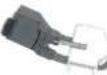 L20/B4Ref. 067882 L20/B4Ref. 067882 | ||
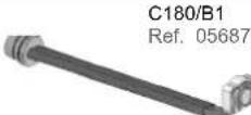
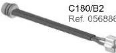
Explore the full range |  S180/B1Ref. 064881 S180/B1Ref. 064881 |  S180/B2Ref. 064928 S180/B2Ref. 064928 |  L180Ref. 059795 L180Ref. 059795 |  L20 ALUGLOVESRef. 069114 L20 ALUGLOVESRef. 069114 | ||
 S180/B3 WRef. 067899 S180/B3 WRef. 067899 |  S180 D20Ref. 069985S180 D25Ref. 069992S180 D30Ref. 070592 S180 D20Ref. 069985S180 D25Ref. 069992S180 D30Ref. 070592 |  L180 D60Ref. 069923L180 D70Ref. 069930L180 D80Ref. 069121 L180 D60Ref. 069923L180 D70Ref. 069930L180 D80Ref. 069121 |  L180 D90Ref. 069947L180 D100Ref. 069954L180 D110Ref. 069961 L180 D90Ref. 069947L180 D100Ref. 069954L180 D110Ref. 069961 | |||
 S180 D35Ref. 070608S180 D40Ref. 070615S180 D45Ref. 070622 S180 D35Ref. 070608S180 D40Ref. 070615S180 D45Ref. 070622 |  S180 D50Ref. 070639S180 D55Ref. 070646 S180 D50Ref. 070639S180 D55Ref. 070646 |  L180 D120Ref. 069978 L180 D120Ref. 069978 | ||||
Explore the full range
DESCRIPTION & USE OF INDUCTORS

All the procedures described below must be carried out by trained staff. It is a good idea to carry out tests on metal sheets or wrecks.
GLASS INDUCTOR
Glass inductor
ref. 053373
natural_image
Coiled black cable with a connector, no visible text or symbols
Description
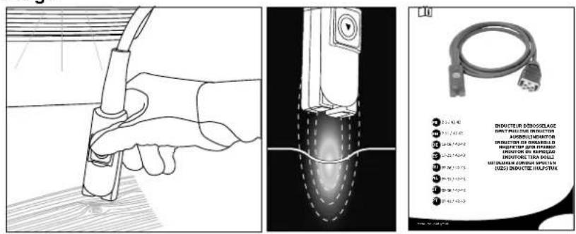
This inductor is designed specifically for removing glued windows (rear window, rear quarter window, panoramic roof, etc.), as well as sanding off gravel-chip scratches from the bottom of the bodywork. It can also be used to remove welded sheets. The automatic mode is particularly recommended for windscreen removal.
Removing glass
◇ Preparation
- Remove any exterior trim beforehand: windows with crimped-metal or plastic trim. For trims that cannot be removed, heat the holding weld from the inside.
- It is recommended to also remove any interior trim and other component parts, such as clips and dowels, that may be used to hold the window in place.
- Disconnect antennas and heated-glass systems.
- Stick protective tape around the edge of the glass to prevent damaging the painted surfaces during handling.
- Stick protective tape to the glass inductor to avoid scratching the glass. Replace the tape after removing each window.
- Clean the glass completely before beginning its removal.
◇ Heating phase & glass removal

The greatest risk of damage to the paintwork is at the beginning of the heating process, as it is more difficult to insert wedges between the glass and the bodywork.
Start in one corner and heat each side of that corner before progressing to opposite corners.
If the glass is damaged, start at the corner to be repaired and work towards the unbroken part of the glass.
natural_image
Diagram of a car interior showing a curved door, internal component, and directional arrows indicating flow or movement (no text or symbols)
Welded edges on which the glue joints rest

Visible painted surfaces not to be heated

Directions of heating progress
7. From a corner, place the inductor opposite the urethane-adhesive seal to easily remove the glass.
Some vehicles have narrow, welded edges, so heating the inductor can cause the painted surface to become visible, potentially compromising its appearance. In this case it is recommended to cool the outer surface with a damp cloth or a spray coolant. Move the inductor towards the middle of the window so that it is at least two cm from the visible, painted area.
- Move the torch back and forth by approximately 30 cm over both sides of the aforementioned seal. Finding the right heating speed: too slow a pace will result in excessive, localised heating. This is inefficient as it reduces the heat generated at the welded edge. too high a pace will not allow sufficient heating of the welded edge or the urethane-adhesive seal. When the urethane-adhesive bead's optimum temperature has been reached, a little smoke will be released.

If thick smoke appears, stop heating immediately. Move away from the area to avoid breathing in the fumes and try to identify the cause of the smoke. The heating of urethane glue causes the release of hydrogen cyanide, which is very dangerous for humans.
natural_image
Diagram of a car interior showing airflow or heat transfer from a vent to a handle (no text or symbols)- Apply pressure from inside the vehicle without forcing the seal to break. Causing the adhesive to lift-up and come away can take a few minutes. Once the seal has come off, it will not reattach to the metal.
When the corner of the glass lifts up, slide a plastic wedge into the gap between the glass and the welded edge. Be careful not to exert too much force which could break the window.
- Once the corner of the pane has come loose, repeat the heating process along the length and height of the pane, positioning wedges under the pane as you go.
| Glass Material Fragility of the glass | Time taken for removal depending on the size of the vehicle | ||
| Front windscreen Laminated glass +++ 20 minutes to 1 hour | |||
| Rear window | Annealed glass + 10 to 20 minutes | Quarter glass | |
| Front and rear-door windows | |||
ADHESIVE INDUCTOR
Body inductors
ref. 053359
natural_image
Coiled black cable with a white bandage and a small connector attached (no text or symbols visible)
Description
This inductor is designed to remove door strips, logos and lettering, as well as advertising and decorative stickers, without causing any damage in just a few minutes.
Usage
- How to heat painted panels
- Select Auto mode or set the power to a low level (10 to 30% of its maximum heating capacity).
- Position the inductor just above the area to be heated. There must be no contact between the inductor and the area or element being heated.
- When using the machine's heating function, use a circular or back-and-forth motion over the area to be heated.

If the inductor remains on the same area for too long, the paint can burn. To avoid this, it is necessary to keep the inductor constantly moving (in a back-and-forth or circular movement).
- For removing decals, vinyl stickers or stuck-on roof-rack bars.
natural_image
Line drawing of a printer with a cover and paper strip, emitting steam (no text or symbols)Follow the three steps described above (see the section on heating painted sheets). Heat for a few seconds and try to lift one edge of the item. If it starts to peel up easily, the required temperature has been reached, if not, continue heating for a few more seconds and try again.

Certain component parts that have been glued for a long time often require a longer heating time. If a decal is overheated, it often becomes soft and blistered. If this happens, allow to cool and then try again to remove the decal by peeling it off. Be careful not to burn the paintwork! If the sheet is sufficiently heated, the door mouldings should come off easily, taking the glue with them.
- For the removal of mouldings glued to the bodywork.
Body-side mouldings are removed in the same way as decals and stickers. A higher power or a longer time is needed for removing thicker mouldings. The metal under the mouldings is further away from the inductor.
- Select Auto Mode or set the power to a mid-level (40-60% of its maximum power).
- Position the inductor parallel to the work surface to ensure even heat distribution.
- Use a back-and-forth movement along the length of the moulding. Start from one end of the moulding. Slowly move back and forth over a few centimetres until the edge of the moulding can be easily peeled off.
- Then, slowly move the inductor further along the moulding while detaching it from the bodywork.

The adhesive tape is usually removed with the moulding. If there is glue or tape stuck to the bodywork, then move the inductor more slowly or increase the power.
• How to heat car-body parts
In winter or in cold climates, the part of the car's body to which decals, stickers or trims are to be applied must be preheated in the workshop to allow the adhesives to bond.
- Set the power to a low level (10 to 30% of its maximum power).
- Use circular or back-and-forth movements on the area being preheated.
PAINTLESS DEBOSSING INDUCTOR
Paintless dent-removal inductor
ref. 054776 (optional)
natural_image
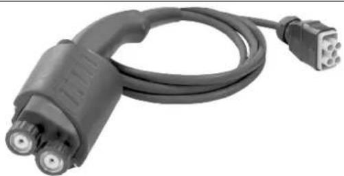
Coiled black cable with two connectors, no visible text or symbols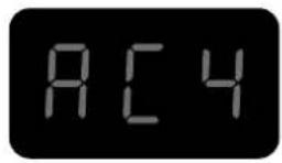
Description
This bodywork inductor has been designed for repairing minor bodywork dents caused by hail damage for example, without the need to retouch the paintwork. Stripping the insides of the parts that are going to be smoothed out is not necessary, this is because the sheet metal is heated from the outside and only to a very limited extent.
Usage
Refer to the instructions supplied with the product for advice on how to use it.
Spiral inductor
ref. 054783 (optional)
natural_image
Coiled black electrical plug with two connectors (no text or symbols visible)
Description
This inductor is designed to easily heat, release and remove all mechanical elements in seconds: seized bolts/nuts, screws, exhaust flanges, track rods, shock absorbers... etc.
Usage
natural_image
Technical line drawing of a mechanical assembly showing a shaft and housing with a valve (no text or symbols)
Refer to the instructions supplied with the product for advice on how to use it.
CONSUMABLES
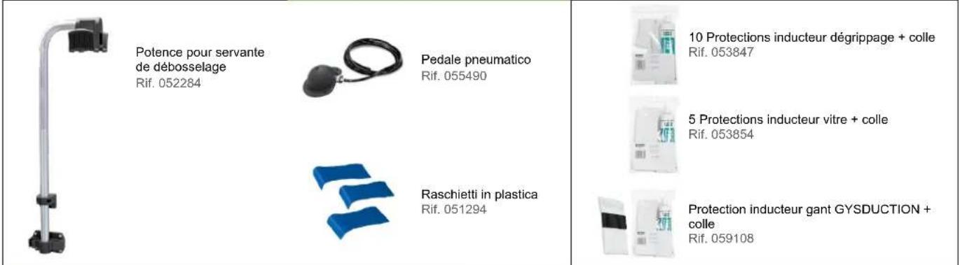
Cloths for induction heaters
Fibreglass cloths used on glass inductors, and also on seized inductors, can wear out from repeated use and from rubbing against the parts to be heated. If these cloths need to be replaced, GYS has provided the required kits' reference numbers below.
053854 FIVE-PIECE GLASS INDUCTOR MAINTENANCE KIT & GLUE
059108 ONE INDUCTOR PROTECTION GLOVE & GLUE
Freeze spray
This freeze spray is particularly useful for unpainted, dent-removal operations and for cooling heated parts.
048898 SET OF 12 COOLING SPRAYS -50°C / 400 ML
DEFAULT CODES
CODE MEANING
| E - 1 Pedal activated on power-up. |
| E - 2 Glass-inductor button activated on power-up. |
| E - 3 Front panel ON/OFF button pressed at power-up. |
| E - 4 Overcurrent in the inductor (either due to being too hot or a short circuit). |
| E - 5 Faulty inductor (cut or disconnected wire). |
| NO- ACC Attachment not connected. |
| AC - Attachment not recognised. |
«DRAINAGE» MODE
This function can only be used if the heating process is not activated (green button off).
- Press the inductor-change button (11), the pump will stop and the LED (10) will light up.
- Place the lance in its holder. Put the cable on the ground to avoid fluid loss.
- Unscrew the inductor with the 27 key (supplied with the product).
- Press and hold the heat-enable button (2) for three seconds until it lights up.
-
Position the lance over a container with a capacity of at least 10 litres.
-
Press the lance button (12). The pump will run either until the flow rate falls below one litre/min or for two minutes. The display shows the flow rate in decilitres per minute. To stop the pump during a cycle, press any button.
-
To completely drain the coolant system, blow (30PSI ≈ 2 bar) into the lance's tip until you hear air or see coolant spraying out of the tank.
-
To drain the remaining liquid from the bottom of the tank, use a vacuum pump or tilt the product towards the front.
natural_image
Technical line drawing of a mechanical device with fan, wheels, and handle (no text or symbols)- To refill the coolant, follow the instructions for the machine's first use.
It is advisable to change the coolant every year, otherwise the COMBlduction lance will be damaged.
It is preferable to use the special welding coolant offered with the Combiduction (see the section entitled 'Maintenance').
COOLING SYSTEM AND «FORCED COOLING» MODE.
When the coolant's temperature reaches 35^ (95°F), the fan will start. As soon as its temperature drops below 35^ , it will switch off again.
During long heating periods, the COMBIDUCTION has a forced cooling mode. To switch it on:
- Flip the main switch (1) to the ON position.
The machine carries out its start-up phase for two seconds. - Press the heat-release button (2). The heat-release button (2) and the LED indicator light (12) will light up, indicating that the product is now ready to heat.
- Press and hold (>3 seconds) the inductor-change button (11). This will activate the «Forced Cooling» mode.
The fan will then start automatically. The message «Fan ON» will appear on the display screen.
To stop the «Forced Cooling» mode, repeat step three. The message «Fan OFF» will appear on the display screen.
MAINTENANCE
General guidelines
- It is advised to change the coolant every year to avoid damaging the COMBIDUCTION machine's lance. Before adding the coolant, dust the product and thoroughly check for leaks.
- Preferably use the special welding coolant supplied with the COMBIDUCTION machine. Do not use automotive coolant. Only use coolants with low electrical conductivity.
- Regularly check that the tiller bolts are tightly screwed and that the electrical power connections are in good condition.
recommended torque for power screws:
| Screw size M5 M6 M8 M10 hose | clamp | Gas 1/43/8 Gas | M28 M32 | Inductor 16/22 | ||||
| Material steel steel brass brass | copper copper copper | |||||||
| Torque | 4 Nm | 6 Nm | 7 Nm | 7 Nm | 2.5 Nm | 4 Nm | 7 Nm max | 7 Nm max |
- It is essential that the product's maintenance is carried out by authorised, qualified personnel who are aware of the recommendations outlined in this manual.
- Never clean, oil or carry out maintenance on the product whilst it is in operation.
- Before undertaking any maintenance, set the On/Off switch (1) to the «0» position to switch off the product. Then, disconnect it from the mains supply to avoid electric shocks or other hazards resulting from improper handling.
- Do not wear rings, watches, jewellery or hanging clothes such as ties, ripped clothing, scarves, unbuttoned jackets or open zips that could be caught whilst working.
- Instead, wear protective clothing specifically designed to prevent accidents, such as: non-slip shoes, hearing protection, safety glasses and safety gloves, etc.
- Never use petrol or flammable solvents to clean the product. Use water instead and, if necessary, non-toxic commercial solvents.
- After maintenance, always reassemble the product's metal casings before restarting the machine.
- The ferrite on an inductor can be replaced if damaged.
To replace it, you need to:
- remove the protective cover.
- use a hot-ait paint stripper helps to remove the ferrite from the copper.
- clean the copper thoroughly.
- glue down the new ferrite with the specially-designed ferrite resin.
- position the new ferrite with its covering.
- wait for the adhesive to set completely before using the inductor.
Preventive maintenance
Thorough inspections at regular intervals are necessary to detect and eliminate defects quickly, so that they do not cause damage to the appliance.

Whenever you need to use the COMBIDUCTION equipment, first check the appliance's safety features and any anomalies that may affect the machine's correct operation. Check daily for signs of wear.

The operational safety of the product can only be guaranteed if repairs are carried out using original spare parts and if the maintenance instructions are properly followed.
After each use, when the product is switched off, it must be immediately cleaned to remove any dust or dirt that may reduce the efficiency of the ventilation system and also affect the product's correct functioning and its life span.
Before each use, check that the machine is functioning properly, along with the safety equipment and all the electrical connection cables.

Carry out periodic visual checks for fluid leaks and check that vents are not obstructed.
ELECTRICAL CONNECTIONS
This product is designed to operate with a single-phase mains voltage of 165 V to 265 V.
For 230 V single-phase electrical installations:
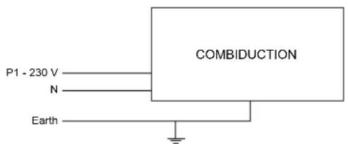
For three-phase electrical installations:
AUTO-INDUCTORS
ADDITIONAL ACCESSORIES CONSUMABLES AUTO INDUCTORS
POWERDUCTION CONSUMABLES
| Ferrite Inductor B1 Ref. 053712 | Protective Ferrite Casing B1 Ref. 056909 | Mounting bell for inductor POWERDUC-TION L180 spiral Ref. 069701 | Two-Part Power Epoxy Adhesive Glue - 2 x 15 g Ref. 056909 | Coolant spray -50℃ Ref. 048898 | Coolant 5 l - Ref. 052246 10 l - Ref. 062511 |
| Ferrite Inductor B2 Ref. 053458 | Protective Ferrite Casing B2 Ref. 056916 | ||||
| Ferrite Inductor B3 Ref. 067875 | 10 logo strips Ref. 051492 | ||||
| Ferrite Inductor B4 Ref. 053755 | Protective Ferrite Casing B4 Ref. 054844 |
WARRANTY CONDITIONS
The warranty covers all defects or manufacturing faults for a period of two years starting from the date of purchase (parts and labour).
The warranty does not cover:
- Any other damage caused by the machine's transportation.
• The general wear and tear of parts : (e.g. cables, clamps, concentrators and ferrite, etc.). - Incidents caused by misuse (misfeeding, dropping or dismantling).
• Environmental failures (pollution, rust or dust). - Problems with consumables, such as removable inductors and ferrites.
• The use of a non-specified coolant.
In the event of a breakdown, return the appliance to your distributor, together with:
- a dated proof of purchase (receipt or invoice etc.).
- a note explaining the breakdown.
natural_image
Close-up of a mechanical component with a curved pipe fitting and directional arrows indicating rotation (no text or symbols visible)Max. Anzugsdrehmoment = 7 Nm
natural_image
Close-up of a mechanical lever assembly with a pin and housing (no visible text or symbols)natural_image
Coiled black cable with a connector, no visible text or symbols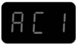
Beschreibung
natural_image
Diagram of a car interior showing a curved door, cable, and internal component with directional arrows (no text or symbols)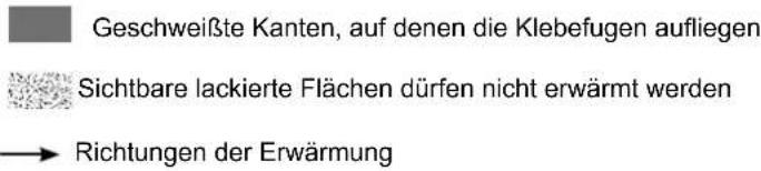
natural_image
Diagram of a car interior showing airflow or exhaust flow with arrows indicating direction (no text or symbols)natural_image
Coiled black cable with a white plastic band attached, next to a small electronic component (no text or symbols visible)
Beschreibung
natural_image
Line drawing of a printer with a cover and paper, no text or symbols presentnatural_image
Coiled black cable with two connectors, no visible text or symbols
natural_image
Coiled black electrical plug with two connectors (no text or symbols visible)
Beschreibung
natural_image
Technical line drawing of a mechanical device with heat exchangers and wheels (no text or symbols)natural_image
Open black toolbox containing medical or laboratory equipment with wires and a small device (no visible text or symbols)natural_image
Three types of wires with black and white bands, no text or symbols visibleZUSÄTZLICHES ZUBEHÖR
natural_image
Metallic stand with attached black connectors (no text or symbols visible)natural_image
Close-up of a mechanical component with a cylindrical shaft and circular features, no visible text or symbols.natural_image
Close-up of a mechanical lever assembly with a white handle and attached components (no visible text or symbols)| Inductores completos Adaptadores | |||||||
 |  | 28SRef. 064485 | 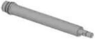 | 28LRef. 064492 | |||
C180/B1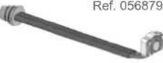 | Inductores | ||||||
 | S90Ref. 058927 |  | S70Ref. 061569 |  | L90Ref. 059788 | 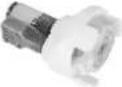 L180 ESPIRALRef. 065000 L180 ESPIRALRef. 065000 | |
 |  | S180Ref. 059269 | 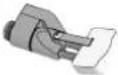 | S20/B1Ref. 064874 |  | L70 (70°)Ref. 059771 |  L20/B4Ref. 067882 L20/B4Ref. 067882 |
Descubra la gama completa |  | S180/B1Ref. 064881 |  | S180/B2Ref. 064928 |  | L180ref. 059795 |  L20 Guante AluRef. 069114 L20 Guante AluRef. 069114 |
 | S180/B3 WRef. 067899 |  | S180 D20Ref. 069985S180 D25Ref. 069992S180 D30Ref. 070592 |  | L180 D60Ref. 069923L180 D70Ref. 069930L180 D80Ref. 069121 | 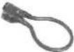 L180 D90Ref. 069947L180 D100Ref. 069954L180 D110Ref. 069961 L180 D90Ref. 069947L180 D100Ref. 069954L180 D110Ref. 069961 | |
| S180 D35Ref. 070608S180 D40Ref. 070615S180 D45Ref. 070622 | S180 D50Ref. 070639S180 D55Ref. 070646 | L180 D120Ref. 069978 | |||||
28L Ref. 064492
natural_image
Coiled black cable with a connector, no visible text or symbols
Descripción
natural_image
Diagram of a car interior showing airflow or movement around a vehicle component (no text or symbols)natural_image
Diagram of a car's front and rear door assembly showing internal components and airflow direction (no text or labels)natural_image
Coiled black cable with a white plastic band attached, next to a small electrical plug (no text or symbols visible)
Descripción
natural_image
Line drawing of a printer with a cover and paper, showing no text or symbolsnatural_image
Coiled black cable with two connectors, no visible text or symbols
Descripción
natural_image
Line drawing of a hand holding a tool with a curved handle, no text or symbols present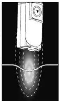
natural_image
Diagram of a mechanical device with internal flow visualization (no text or symbols)
natural_image
Coiled black electrical plug with two connectors (no text or symbols visible)
Descripción
natural_image
Technical line drawing of a mechanical assembly showing a shaft and flange with a circular component (no text or symbols)
natural_image
Technical line drawing of a mechanical device with wheels and a handle (no text or symbols)natural_image
Open black tool kit with coiled wires and a small device, no visible text or symbols
Hilo espiral ∅ 18 mm
Ref. 054806
Hilo espiral ∅ 24 mm
Ref. 054790
Hilo espiral ∅ 30 mm
Ref. 055469
natural_image
Pure electrical circuit lines without any symbolsHilo trenzado
Ref. 054813
Hilo rector
Ref. 054868
ACCESORIOS ADICIONALES CONSUMIBLES COCHE INDUCTORES
natural_image
Metallic vertical support bracket with black connectors (no text or symbols visible)
Ferrita B2
Ref. 053458

Ferrita B3
Ref. 067875

Ferrita B4
Ref. 053755
natural_image
Close-up of a mechanical component with a cylindrical shaft and circular end caps, showing internal rotation (no text or symbols)Макс момент затяжки = 7Нм
natural_image
Close-up of a mechanical lever assembly with a pin and housing (no visible text or symbols)natural_image
Coiled black cable with a connector, no visible text or symbols
Описание
natural_image
Diagram of a car interior showing airflow or movement around a vehicle handle (no text or symbols)natural_image
Diagram of a car interior showing airflow or airflow path with arrows indicating direction (no text or symbols)natural_image
Coiled black cable with a white bandage and a connector pin (no text or symbols visible)
Описание
natural_image
Line drawing of a person's seat with a credit card and a flag, no text or symbols presentnatural_image
Coiled black cable with two connectors and a connector pin (no text or symbols visible)
Описание
natural_image
Coiled black electrical plug with two connectors (no text or symbols visible)
Описание
natural_image
Technical line drawing of a mechanical device with fan, wheels, and internal grid structure (no text or symbols)WAARSCHUWINGEN - VEILIGHEIDSINSTRUCTIES
ALGEMENE INSTRUCTIES
BESCHRIJVING VAN HET APPARAAT (Fig I)
natural_image
Close-up of a mechanical component with a curved arrow indicating rotation (no visible text or symbols)natural_image
Close-up of a mechanical component with a lever and mounting bracket (no visible text or symbols)natural_image
Coiled black cable with a connector, no visible text or symbols
Beschrijving
natural_image
Diagram of a car interior showing airflow or movement around a curved mechanical component (no text or symbols)
natural_image
Diagram of a car interior showing airflow or airflow direction with arrows indicating movement (no text or symbols)natural_image
Coiled black cable with a white plastic band attached, next to a small plug (no text or symbols visible)
Beschrijving
natural_image
Line drawing of a car interior with a striped blanket and 'AUTO' label, no readable text or symbols beyond the labelnatural_image
Coiled black cable with two connectors, no visible text or symbols
Beschrijving
natural_image
Line drawing of a hand holding a tool with a curved handle, no text or symbols present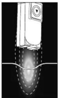
natural_image
Diagram of a mechanical component with internal flow pattern (no text or symbols)
natural_image
Coiled electric vehicle charging plug with two connectors (no text or symbols visible)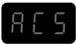
Beschrijving
natural_image
Technical line drawing of a mechanical assembly showing a shaft and housing with a rotating component (no text or symbols)
059108 1 BESCHERMING INDUCTOR LIJM
Afkoelende spray
natural_image
Technical line drawing of a mechanical device with wheels and a handle (no text or symbols)natural_image
Close-up of a black mechanical component with a circular arrow indicating rotation (no visible text or symbols)natural_image
Close-up of a mechanical device with a rod and cable, no visible text or symbolsnatural_image
Coiled black cable with a connector, no visible text or symbols
Descrizione
natural_image
Diagram of a car's side profile showing airflow and structural components (no text or labels)
natural_image
Diagram of a car's side panel showing airflow direction and component placement (no text or symbols)natural_image
Coiled black cable with a white bandage and a connector pin (no text or symbols visible)
Descrizione
natural_image
Line drawing of a car interior with a striped blanket and 'AUTO' label on the back panel (no readable text or symbols beyond basic markings)natural_image
Coiled black cable with two connectors, no visible text or symbols
Descrizione
natural_image
Coiled black electrical plug with two connectors (no text or symbols visible)
Descrizione
natural_image
Technical line drawing of a mechanical device with wheels and a connecting rod (no text or symbols)ACCESSORI AGGIUNTIVI
natural_image
Technical line drawing of a mechanical component with no visible text or symbols| 1 | Axe de roue / Wheel axle / Radachse / Eje de la rueda / Ось колеса / Wielas / Asse delle ruote 91100ST | |
| 2 | Poignée plastique / Plastic handle / Kunststoffgriff / Mango de plástico / Пластиковая ручка / Kunststof handvat / Maniglia in plastica | 56014 |
| 3 | Roue / Wheel / Rad / Rueda / Koleco / Wiel / Ruota 71375 | |
| 4 | Ventilateur / Ventilator / Beatmungsgerät / Ventilador / Вентилятор / Ventilator / Ventilatore | 51021 |
| 5 | Presse étoupe / Cable gland / Kabelverschraubung / Glándula de cable / кабельный ввод / Klier / Pressacavo | 71164 |
| 6 | Enrouleur de Cables - Pinces / Cable Reel - Pliers / Kabeltrommel - Zange / Carrete de cable - Alicates / Кабельный барабан - Клещи / Kabelhaspel - Tang / Avvolgicavo - Pinze | 56131 |
| 7 | Pompe / Pump / Pumpe / Bomba / Hacoc / Pomp / Pompa 71746 | |
| 8 | Clavier / Keyboard / Tastatur / Teclado / Kлавиатура / Toetsenbord / Tastiera 51967IND1 | |
| 9 | Interrupteur Marche/Arrêt / On/Off switch / Ein/Aus-Schalter / Interruptor de encendido y apagado / Переключатель Вкл/Выкл / Aan/uit-schake-laar / Interruttore On/Off | 51075 |
| 10 | Capteur de débit / Flow sensor / Durchflussensor / Sensor de flujo / Датчик расхода / Stromingssensor / Sensore di flusso | 81100 |
| 11 | Roue pivotante avec frein / Swivel wheel with brake / Schwenkrad mit Bremse / Rueda giratoria con freno / Шарнирное колесо с тормозом / Zwenkwiel met rem / Ruota girevole con freno | 71360 |
| 12 | Self / Self / Spule / Self / Inductie spoel / Self 63691 | |
| 13 | Transformateur / Transformer / Transformator / Transformador / Трансформатор / Transformator / Trasformatore | 96100 |
| 14 | Circuit alimentation & CEM / Power supply & EMC circuit / Stromversorgung & EMV-Schaltung / Fuente de alimentación y circuito EMC / Источник питания и электромагнитная цепь / Stroomvoorziening & EMC-circuit / Alimentazione e circuito EMC | E0100C |
| 15 | Transformateur / Transformer / Transformator / Transformador / Трансформатор / Transformator / Trasformatore | 96175 |
| 16 | Bouton lumineux vert / Green illuminated button / Grün beleuchtete Taste / Botón verde iluminado / Зеленая кнопка с подсветкой / Groen verli-chte knop / Pulsante verde illuminato / | 51403 |
| 17 | Circuit CEM / EMC circuit / Leistungsfluss-EMV-Schaltung / Circuito de conducción de energía EMC / Электромагнитная цепь электромагнитной совместимости / Elektriciteitsnet EMC-circuit / Circuito EMC a conduzione di potenza | 97472C |
| 18 | Circuit primaire / Primary circuit / Primärer Kreislauf / Circuito primario / Первичный контур / Primair circuit / Circuito primario | E0078C |
| 19 | Circuit adaptation interface clavier / Keyboard interface adaptation circuit / Schaltung zur Anpassung der Tastaturschnittstelle / Circuito de adaptac-ión de la interfaz del teclado / Схема адаптации интерфейса клавиатуры / Toetsenbordinterface aanpassingscircuit / Circuito di adattamento dell'interfaccia della tastiera | 97782C* |
| 20 | Lance / Launch / Starten Sie / Lanzamiento / Заныск / Lancering / Lanciare 94196 | |
| 21 | Cordon secteur / Power cord / Netzkabel / Cable de alimentación / шнур питания / Stroomkabel / Cavo di alimentazione | 21556 |
| 22 | Pied de maintiein potence / Handle foot for gallows / Handgriff-Fuß für Galgen / Pie de mango para la horca / Ручка-ножка для виселицы / Handgreepvoet voor galg / Piedino per forca | 56023 |
| 23 | Maintien haut potence / High gallows support / Hohe Galgenunterstützung / Soporte de la horca alta / Высокая виселица поддержка / Hoge galgsteun / Supporto per forca alta | 56024 |
| 24 | Potence support cable / High gallows support / Kabelhalterung / Soporte del cable / Кронштейн опоры кабеля / Kabelsteunbeugel / Staffa di supporto del cavo | fab050ST |
| 25 | Mat potence / Mat gallows / Matten-Galgen / La horca de esteras / ковровая виселица / Matgalg / Forca di stuoia 91025ST | |
| 26 | Support câble pour potence / Cable support for a gallows / Kabelhalterung für einen Galgen / Soporte de cable para una horca / Кабельная опора для виселицы / Кабельная опора для виселицы / Kabelsteun voor een galg / Supporto per cavo per forca | 56019 |
| 27 | Condensateur de résonnance / Resonance capacitor / Resonanzkondensator / Condensador de resonancia / Резонансный конденсатор / Resonantiecondensator / Condensatore di risonanza | 52250 |
| 28 | Circuit Combo / Combo Circuit / Combo-Schaltung / Circuito Combo / Комбинированная схема / Combo Circuit / Circuito combinato | E0027C |
| 29 | Interrupteur pneumatique / Pneumatic switch / Pneumatischer Schalter / Interruptor neumático / Пневматический выключатель / Pneumatische schakelaar / Interruttore pneumatico | 71179 |
| 30 | Bouchon étanche transport / Watertight transport plug / Wasserdichter Transportstopfen / Tapón de transporte estanco / Водонепроницаемая транспортная заглушка / Waterdichte transportstop / Tappo di trasporto a tenuta stagna | 43188 |
| 31 | Bouchon de remplissage / Filler cap / Einfülldeckel / Tapón de llenado / Крышка заливной горловины / Vuldop / Tappo di riempimento | 71334 |
| 32 | Ventilateur / Ventilator / Beatmungsgerät / Ventilador / Вентилятор / Ventilator / Ventilatore | 51004 |
| 33 | Carte microcontrôleur / Microcontroller card / Mikrocontroller-Karte / Tarjeta de microcontrolador / Микроконтроллерная плата / Microcontroller kaart / Scheda microcontrollore | 97788C |
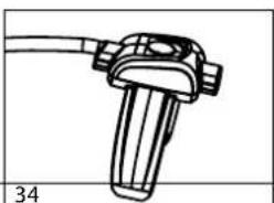
| 34 | Ensemble bouton pour lance / Button assembly for lance / Knopfleiste für Lanze / Conjunto de botones para la lanza / Кнопка в сборе для копья / Knop voor lans / Gruppo di pulsanti per la lancia | S81109 |
| 35 | Connecteur inducteur / Inductor connector / Induktoranschluss / Conector del inductor / Разъем индуктора / Inductor-aansluiting / Connettore induttore | - |