USER MANUAL HW 4500 FCS Comfort AL-KO
natural_image
Technical line drawing of a mechanical device with no visible text or symbols


Inhaltsverzeichnis
D 5
EN 13
NL 21
FR 29
ES 38
IT 47
SL 56
HR 64
PL 72
CS 81
SK 89
DA 97
SV 105
NO 113
FI 121
ET 129
LT 137
LV 145
HU 153
TR 161
RU 169
UK 178
© 2016
AL-KO KOBER GROUP Kötz, Germany
This documentation or excerpts therefrom may not be reproduced or disclosed to third parties without the express permission of the AL-KO KOBER GROUP.
 | HW 4000 FCS COMFORT (Art.Nr. 112 849) | HW 4500 FCS COMFORT (Art.Nr. 112 850) |
 | 1000 W 1300 W | |
 | 230 V AC/50 Hz 230 V AC/50 Hz | |
 | X 4 X 4 | |
 | 78 dB (A) 78 dB (A) | |
 | 8 m 8 m | |
 | 45 m / 4,5 bar 50 m / 5,0 bar | |
 | 4000 l/h 4500 l/h | |
 | 35 °C 35 °C | |
 | 2,0 / 3,5 bar 2,0 / 3,8 bar | |
 | 1" 1" | |
 | 17 kg 17 kg | |
 | 1 | 1 |
 | 17 | 17 | | |
line
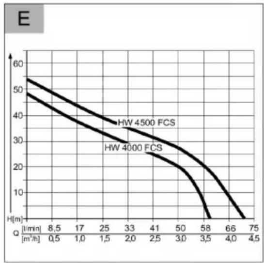
| H [m³/h] | HW 4500 FCS | HW 4000 FCS |
| -------- | ----------- | ----------- |
| 8.5 | 55 | 50 |
| 17 | 50 | 45 |
| 25 | 45 | 40 |
| 33 | 40 | 35 |
| 41 | 35 | 30 |
| 50 | 30 | 25 |
| 58 | 25 | 20 |
| 66 | 20 | 15 |
| 75 | 15 | 10 |
Wolfgang Hergeth
Managing Director
Scope of delivery.... 14
Safety instructions....14
Assembly....15
Startup....15
Maintenance and care.... 16
Storage....17
Disposal....17
Help in case of a malfunction.... 17
LED displays.... 18
Warranty.... 19
EU declaration of conformity....20
PRODUCT DESCRIPTION
This documentation describes various different unit models. Identify your model using the identification plate.
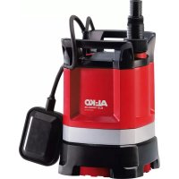
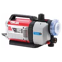
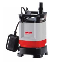
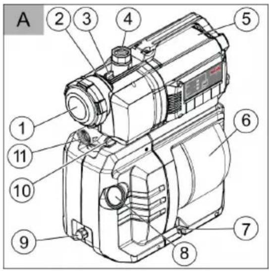
Product overview
(Fig. A - E)
| 1 Clear filter cover |
| 2 Pump housing |
| 3 Filling screw |
| 4 Pump outlet/pressure line connection |
| 5 Motor housing |
| 6 Storage vessel |
| 7 Screw-on point |
| 8 Pressure gauge |
| 9 Drain screw pump chamber |
| 10 Drain screws filter chamber |
| 11 Pump inlet/suction line connection |
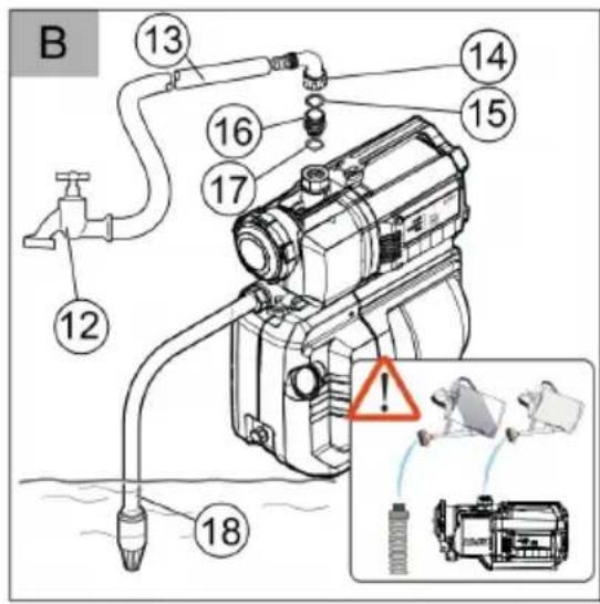
| 12 Water cock |
| 13 Pressure line |
ABOUT THIS HANDBOOK
Read this documentation before starting up the machine. This is a precondition for safe working and flawless operation.
- Observe the safety warnings in this documentation and on the product.
This documentation is a permanent integral part of the product described and must be passed on to the new owner if the product is sold.
Explanation of symbols

CAUTION!
Following these safety warnings carefully can prevent personal injury and/or material damage.

Special instructions for greater ease of understanding and improved handling.
| 14 | Angle nipple |
| 15 | Seal |
| 16 | Connection nipple |
| 17 | Seal |
| 18 | Suction line |
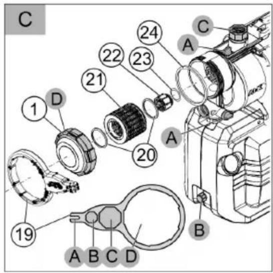
| 19 | Filter spanner |
| 20 | Filter seal |
| 21 | Filter |
| 22 | Check valve |
| 23 | Seal non-return valve |
| 24 | Housing seal |
| 25 | Screw-in nipple |
| 26 | Seal |
| 27 | Measuring unit float body |
| 28 | Valve closing cover |
| 29 | Valve |
Inox stainless steel
Units marked with the designation "INOX" are supplied in stainless steel. The structure and function are unaffected by this.
Designated use
The unit is intended for private use in the house and garden, and is exclusively suited to pumping clean water and rainwater.
It is suitable for:
Watering the garden and premises
Water supply in the house
■ Pressure increase in the water supply.

If the pressure of the water supply is increased, the local regulations must be observed. Your sanitation expert will provide the necessary information.
Possible misuse
The house water system is not suitable for the conveying:
Water containing sand, salt water and waste water with textile and paper content
■ Aggressive, corrosive, explosive or fuming chemicals or liquids
Fluids above 35°C.

The unit is not allowed to be used for pumping water for use in food or beverages.
The unit is not suitable for continuous use.
SCOPE OF DELIVERY
The unit is supplied ready for operation, with key for filter cover, elbow nipple and operating instructions.
Thermal protection
The unit is fitted with a thermal protection switch which switches the motor off in the event of overheating. The pump switches on again automatically after a cooling down period of approx. 15 - 20 minutes.
Dry-run protection
The unit is provided with dry-run protection. The dry-run protection switches the pump off after about 90 seconds if water is not being drawn up or if the suction line is damaged.
Pressure switch
The house water system is provided with a pressure switch. This pressure switch automatically switches the pump off and on when the set pressure is reached.
⇒ Set pressure values: see technical data.
LED monitoring
For monitoring the operational conditions, and for displaying the fault messages, the house water system is equipped with LED monitoring.
SAFETY INSTRUCTIONS

CAUTION!
Risk of injury!
Use the machine and the extension cable only in perfect working order. Damaged equipment may not be operated. Do not disable safety and protective devices!
Children, or people who are not familiar with the operating instructions, are not allowed to use the machine.
- Never lift, transport or suspend the unit using the connection cable.
■ Unilateral modifications or conversions of the unit are prohibited.
Electrical safety

CAUTION!
Danger when touching voltage conducting parts!
Disconnect the plug from the mains if the extension cable is damaged or severed! We recommend connecting a RCD (residual current operated device) having a nominal residual current of < 30 mA.
The pump may not be operated while people are in the pool or pond.
The house mains voltage must agree with the details quoted in the technical data, do not use any other supply voltage.
The unit must only be operated with an electrical installation in accordance with DIN/VDE 0100, Part 737, 738 and 702. Protection must be provided by a 10 A line protection switch and a RCCD (residual current operated device) having a nominal residual current of 10/30 mA.
Use only extension cables that are suitable for use outdoors - minimum cross-section 1.5 mm². Cable drums should always be unrolled completely.
■ Damaged or brittle extension cables must not be used.
→ Check the condition of your extension cable each time you start to use the equipment.
ASSEMBLY
Erecting the equipment
- Prepare a flat and solid erection site.
- Erect the machine horizontally and protected against flooding.
- Bolt the house water system securely at the bolting points (Fig. A -7) if necessary.
- The house water system must be protected from rain and direct water jets.

In daily operation (automatic mode), you must ensure, by suitable measures, that, in the event of a fault in the equipment, consequential damage caused by flooding is excluded.
Connecting the suction line
- Select the length of the suction line (Fig. B-17) to make sure that the house water system cannot run dry. The suction line must always be at least 30 cm under the surface of the water.
- Connect the suction line. Make sure that the connection is tight, but do not damage the thread.
We recommend using flexible lines at the pump inlet (Fig. A -10). This ensures that pressure or tension on the house water system cannot be exerted.
- If the water has a small amount of sand in it, a pre-filter must be fitted between the suction line and the pump inlet. Ask your expert dealer about this.
- Always lay the suction line with an upward gradient.

If the suction height is more than 4 m, you must use a suction hose having a diameter greater than 1". We recommend the use of an AL-KO suction unit with suction hose, suction filter and flow-back stop. Ask your expert dealer.
Fitting the pressure line
- Screw the connecting nipple (Fig. B -16) with the round seal ring (Fig. B -17) into the pump outlet (Fig. A -4).
- Screw the elbow nipple (Fig. B -14) with seal (Fig. B -15) onto the connecting nipple (Fig. B -16) and turn the elbow nipple in the desired direction.
- Fix a pressure line (Fig. B -13) onto the elbow nipple (Fig. B -14).
- Open all the closing off devices (valves, spray nozzles, water cock) in the pressure line.
STARTUP
Check the air pressure in the storage vessel

CAUTION!
The house water system must only be commissioned with a storage diaphragm pressure of 1.5 - 1.7 bar in the storage vessel. Check the air pressure at the valve on the back of the storage vessel before commissioning.
- If necessary, in the pressure line (Fig. B -13), open one of the existing closing off devices (valve, spray nozzle, water cock).
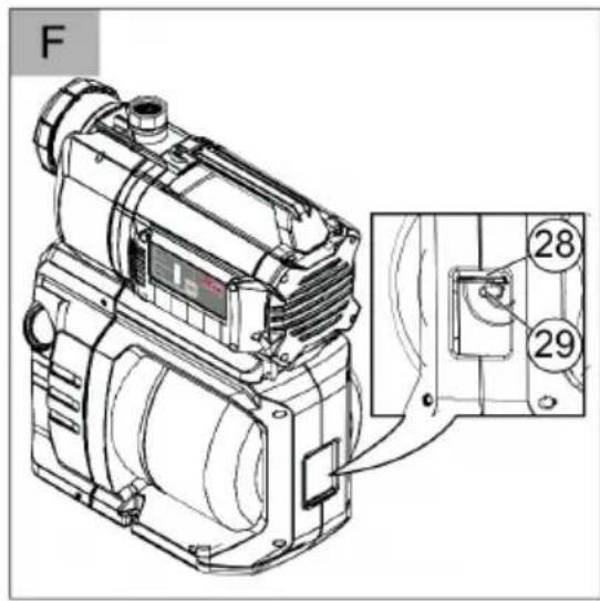
- Slide the closing off cover valve (Fig. F -28) on the back of the storage vessel (Fig. A -6) upwards.
- Check the air pressure at the valve (Fig. F -29) with an air pump or a tyre filler, each having a pressure indicator (pressure gauge).
- If necessary, adjust the air pressure to 1.5 - 1.7 bar.
- Then close the closing off cover valve on the back of the storage vessel again.
- The house water system can now be commissioned.
Filling the house water system

CAUTION!
Before commissioning, the house water system must always be filled up to the overflow with water, so that it can draw water immediately. If the pump runs dry it will be destroyed.

Fill the suction hose with water before screwing in place to reduce the suction time.
- Open the filling screw (Fig. A -3) with the filter key (Fig. C -19/A).
- Fill with water via the filling screw until the pump housing (Fig. A -2) is full.
- Screw the filling screw in.
Switching the pump on
- Open one of the closing off devices (e.g. water cock) in the pressure line.
- Insert the mains plug on the connection cable into the plug socket.
→ The pumps starts to feed.
- When no more air comes out with the water, close the closing off device in the pressure line.
⇒ The pump switches off automatically after the switch-off pressure has been reached. The house water system is ready for operation.
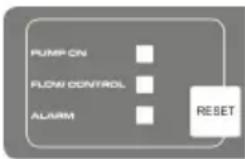
→ The LED displays are off.
⇒ If water is being fed, just the LED display PUMP ON lights up.
Initial commissioning
In the initial commissioning, the LED displays PUMP ON and the LED display FLOW CONTROL flashes.

If no water is being drawn up via the suction line after approx. 90 seconds, the dry running protection system switches the pump off and the LED display ALARM lights up. Check for leaks in the suction line, the filter glass and all screwed fittings, push the RESET button and repeat the initial commissioning process.
Switch the pump off
- Remove the mains plug from the socket
- Close one of the closing off devices (valve, spray nozzle, water cock) in the pressure line (Fig. B -10).

CAUTION!
Danger of injury from hot water
In extended use against the closed pressure side (>10 min.), the water in the pump can be severely heated up and can be emitted in an uncontrolled manner! Isolate the unit from the mains and allow the pump and water to cool down. Start the unit again only after all the faults have been rectified!
The risk of injury from hot water can arise if:
the installation is not correct
■ the pressure side is closed off
■ there is a lack of water in the suction line, or if
■ the pressure switch is defective.
Procedure
- Isolate the unit from the mains and allow the pump and water to cool down.
- Check the unit, the installation and water level.
- Start the unit again only after all the faults have been rectified!
MAINTENANCE AND CARE
Check the air pressure in the storage vessel

CAUTION!
Check the air pressure in the storage vessel at regular intervals. It must not exceed 1.5 bar (see Section "Commissioning: Checking the Air Pressure in the Storage Vessel").
Cleaning the pump

After conveying swimming pool water containing chlorine or fluids that leave a residue, the pump must be flushed out with clear water.
- Isolate the unit from the mains and secure against switching on again.
⇒ The pump stops automatically.
- Flush the pump out with clear water.
- Insert the mains plug into the plug socket.
- Switch the house water system on with the on/off switch (Fig. A -6).
→ The pump starts automatically.
Cleaning the filter
- Unscrew the drain screw filter chamber (Fig. A -10) of the draining opening, drain the filter chamber and close the draining opening again.
- Unscrew the clear filter cover (Fig. A -1) using the filter key (Fig. C -19/D).
- Remove the filter (Fig. C -21) from the filter housing (Fig. A -2) and clean under flowing water.
-
Cleaning the filter housing and clear sight filter cover.
-
Before fitting the filter, check the filter seal (Fig. C -20) and the housing seal (Fig. C -24) for damage, and replace if necessary.
- Fit the filter, screw the filter clear sight cover in place and tighten hand-tight with the filter key.
Cleaning the check valve
- Removing and fitting the filter (see Section "Cleaning the Filter").
- Unscrew check valve (Fig. C -22) and clean under flowing water.
- Replace seal (Fig. C -23) if necessary.
- Fit check valve.
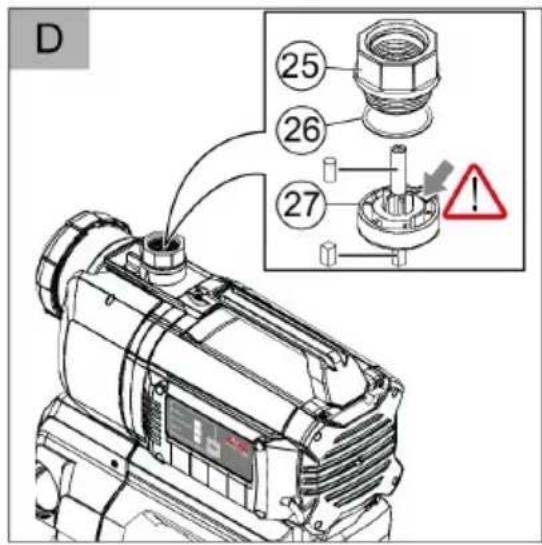
Unscrew float body
- Pressure line (Fig. B -13), with elbow nipple (Fig. B -14), and connecting nipple (Fig. B -16)
- Unscrew screw-in nipple (Fig. D -25) with seal (Fig. D -26). Note the fitting position of the float body (Fig. D -27). Pull out the float body and clean it.
- Replace the float body - note fitting position.
Remove blockages
- Isolate the unit from the mains and secure against switching on again.
- Remove the suction hose from pump inlet.
- Connect the pressure hose to the water supply.
-
Allow water to run through the pump housing until the blockage is removed.
-
Check that the pump is running freely by switching it on briefly.
- Start the house water system again as described.
STORAGE

If there is a risk of frost, the entire system must be drained (pump, lines, storage vessel and filter chamber).
- Drain the suction line (Fig. B -18) and the pressure line (Fig. B -13).
- Unscrew the drain screw on the filter chamber (Fig. A -10) and allow the water to flow out of the pump.
⇒ The water in the storage vessel (Fig. A -6) is pushed out by the air bellows at the same time.
- Unscrew the drain screw on the pump chamber (Fig. A -9) and allow the storage vessel (6) to empty.
- Screw the drain screws (Fig. A -9, 10) back in position and store the pump, lines and storage vessel in a frost-free environment.
DISPOSAL
Do not dispose of worn-out machines or spent batteries (including rechargeable batteries) in domestic waste!
The packaging, machine and accessories are made from recyclable materials and must be disposed of accordingly.
HELP IN CASE OF A MALFUNCTION

CAUTION!
Disconnect the mains plug before any fault rectification work. Faults in the electrical system must be rectified by an expert electrician.
| Malfunction Cause | Rectification | |
| Pump motor does not run | Impeller blocked Cleaning the pump. | Release the motor shaft of the impeller with a screwdriver. |
| Overheating by running dry or water which is too hot (thermal protection switch has switched the pump off). | Check the water level on the suction side. Allow the conveying fluid to cool down. Repair the pump or replace it. |
| No mains voltage Check fuses and power supply. |
| Pump not drawing water | The suction line is not in the water. Submerge the end of the suction line into the water by min. 30 cm. |
Malfunction Cause Rectification
| Suction line blockage Remove dirt from the suction area. |
| Pressure line blocked off Open the closing off devices in the pressure line. |
| Pump drawing air into the suction line Check all the connections in the suction line for leaks. Replace seal ring. |
| Pump has been running dry. Fill the pump housing with water. |
| Pump switches on and off frequently. | Diaphragm is damaged. Have the diaphragm replaced by AL-KO Service Department. |
| Low air pressure in the storage vessel Top up the air in the storage vessel. (Set the diaphragm pressure to 1.5 bar). |
| Pump drawing air, water shortage on suction side. | Switch pump off and allow to cool. |
| Flow rate too low | Suction line blockage Clean the suction area. Replace the filter. |
| Suction head too great Reduce the suction head. |
| Hose diameter too small Replace the pressure hose with one with a larger diameter. |
| Water volume on the suction side to little | Throttle back the pump to adapt the flow rate. |

If the faults cannot be rectified, please contact our Customer Service Department.
LED DISPLAYS
Switching condition LED display Function description/actions
| Normal operation mode |
| Pump switches on and starts to draw water. Pump fills the tank with outlet closed. | LED display PUMP ON lights up. LED display FLOW CONTROL flashes. | Initial commissioning Pump filled with water, suction and pressure side connected, water present on the suction side. Pump connected to mains. |
| Pump runnig. LED | display PUMP ON lights up. Pump delivering water. Water is being drawn off on the pressure side. |
| Switching condition | LED display Function description/actions | |
| Pump switches off via pressure switch. | LED displays off. Pump achieving the set pressure | |
| Fault message |
| Pump switches off via electronics (dry running protection). | LED display ALARM is flashing. Check all screwed fittings, the suction line and filter glass and press the RESET button if necessary. Back to initial commissioning until the pump delivers water.Alarm dry running:This message appears if, for a defined period, (approx. 90 seconds) there is no flow and pressure is not built up. Reset using the RESET button. |
WARRANTY
We will address claims for any defects in materials and workmanship during the statutory period of limitation by means of repairs or replacements of our choice. The period of limitation is governed by the laws of the country in which the machine was purchased.
Our warranty applies only if:
The machine has been properly handled
The operating instructions have been adhered to
■ Original replacement parts have been used
The warranty is no longer in effect if:
■ Efforts have been made to repair the machine
■ Technical modifications have been made to the machine
The machine has not been used for its intended purpose
The warranty does not cover:
■ Damage to paint work through normal use
Parts subject to wear as indicated in the replacement parts list with a box [xxx xxx (x)]
Internal combustion engines – separate warranty conditions of the respective engine manufacturer apply
The warranty period begins with the purchase by the first buyer. The warranty period begins on the date that appears on the original purchase receipt. In the event of a warranty claim, please your contact supplier or the nearest authorised customer service centre with this warranty declaration and the purchase receipt in hand. This warranty does not affect the legal warranty claims by the purchaser against the seller.
We herewith declare that this product, in the version introduced into trade by us, complies with the requirements of the harmonised EU guidelines, EU safety standards and the product-specific standards.
Product Type Manufacturer
| House water system | HW 4000 FCS | AL-KO Geräte GmbH |
| Serial number | HW 4500 FCS | Ichenhauser Str. 14 |
| G3043045 | | D-89359 Kötz |
Duly authorised person EU guidelines Harmonised standards
| Andreas Hedrich | 2014/35/EU | EN 60335-1:2012 |
| Ichenhauser Str. 14 | 2014/30/EU | EN 60335-2-41:2012 |
| D-89359 Kötz | 2000/14/EU (13) | EN 62233:2008 |
| 2011/65/EU | EN 55014-1:2012 |
| 2014/68/EU | EN 55014-2:2016 |
| | EN 61000-3-2:2014 |
| | EN 61000-3-3:2014 |
Sound pressure level
| EN ISO 3744HW 4000 FCSmeasured: 74 dB(A)guaranteed: 78 dB(A)HW 4500 FCSmeasured: 76 dB(A)guaranteed: 78 dB(A) | CE2015 |
Conformity evaluation
VERTALING VAN DE ORIGINELE GEBRUIKERSHANDLEIDING
Inhoudsopgave
Over dit handboek....21
Wolfgang Hergeth
Managing Director
Geluidsniveau
EN ISO 3744
HW 4000 FCS
gemeten: 74 dB(A)
| Uklopno stanje LED indikator Opis funkcije/mjere | |
| Normalan način rada |
| Pumpa se uključuje i počinje s usisavanjem. Pumpa puni spremnik kod zat-vorenog izlaza. | Pali se LED indikator PUMP ON. Tre-peri LED indikator FLOW CONTROL | Prvo stavljanje u pogon: Pumpa se puni vodom, usisna i tlačna strana su zatvorene, na tlačnoj strani je prisutna voda. Pumpa se preuzima u mrežu. |
| Pumpa radi. Pali se | LED indikator PUMP ON. Pumpa crpi vodu. Iz tlačne strane se uzima voda. |
| Pumpa se is-ključuje pomoću tlačne sklopke. | LED indikatori isključeni. Pumpa postiže | namješteni tlak |
| Poruka o grešci |
DEKLARACJA ZGODNOŚCI WE
VEDLIKEHOLD OG PLEIE
Koblingstilstand LED-indikering Funksjonsbeskrivelse/tiltak
Commissioning....131
Wolfgang Hergeth
Managing Director
Уровень звуковой
МОЩНОСТИ
EN ISO 3744
HW 4000 FCS
измерено: 74 дБ(А)
Wolfgang Hergeth
Managing Director
ETK HW 4000 FCS / HW 4500 FCS