
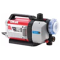
Dive 55003 - Pump AL-KO - Free user manual and instructions
Find the device manual for free Dive 55003 AL-KO in PDF.

| Product type | Submersible pump |
| Brand | AL-KO |
| Model | Dive 55003 |
| Power supply | 230 V, 50 Hz (mains) |
| Thermal protection | Built-in thermal switch, automatic restart after cooling |
| Switch type | Adjustable float switch |
| Intended use | Clear water, rainwater, chlorinated water (pool), drainage, irrigation |
| Excluded liquids | Drinking water, salt water, wastewater, corrosive or flammable liquids |
| Maximum liquid temperature | 35 °C |
| Delivery contents | Pump, power cable, float switch, plastic multi-connection nipple |
| Discharge connection | Plastic multi-connection nipple (adjustable) |
| Non-return valve | Integrated in the discharge head |
| Inlet filter | Yes, removable for cleaning |
| Recommended cable length for float | Approximately 120 mm |
| Recommended electrical protection | Residual current device < 30 mA |
| Maintenance | Clean with clear water after use, especially after chlorinated water |
| Winter storage | Drain completely to avoid freezing |
| Warranty | Legal (according to country of purchase), requires proper use and original parts |
| Spare parts | Available from AL-KO after-sales service |
| Continuous use | Not suitable for continuous operation |
| Weight | Not specified (approx. ~5 kg) |
Frequently Asked Questions - Dive 55003 AL-KO
User questions about Dive 55003 AL-KO
0 question about this device. Answer the ones you know or ask your own.
Ask a new question about this device
Download the instructions for your Pump in PDF format for free! Find your manual Dive 55003 - AL-KO and take your electronic device back in hand. On this page are published all the documents necessary for the use of your device. Dive 55003 by AL-KO.
USER MANUAL Dive 55003 AL-KO
natural_image
Technical line drawing of two cylindrical industrial enclosures with visible internal components and wiring (no text or symbols)


Inhaltsverzeichnis
EN Instructions for use....10
AL-KO KOBER GROUP Kötz, Germany
This documentation or excerpts therefrom may not be reproduced or disclosed to third parties without the express permission of the AL-KO KOBER GROUP.
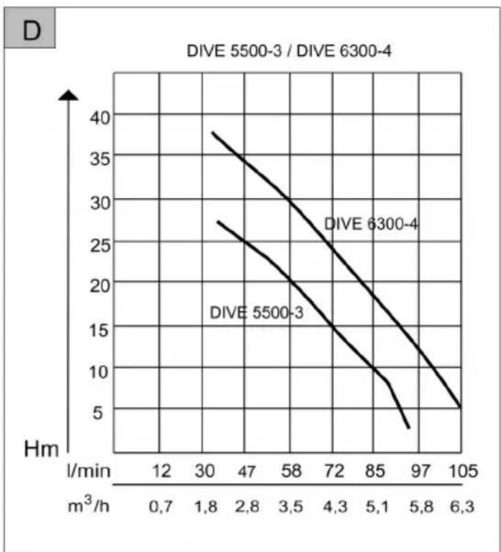
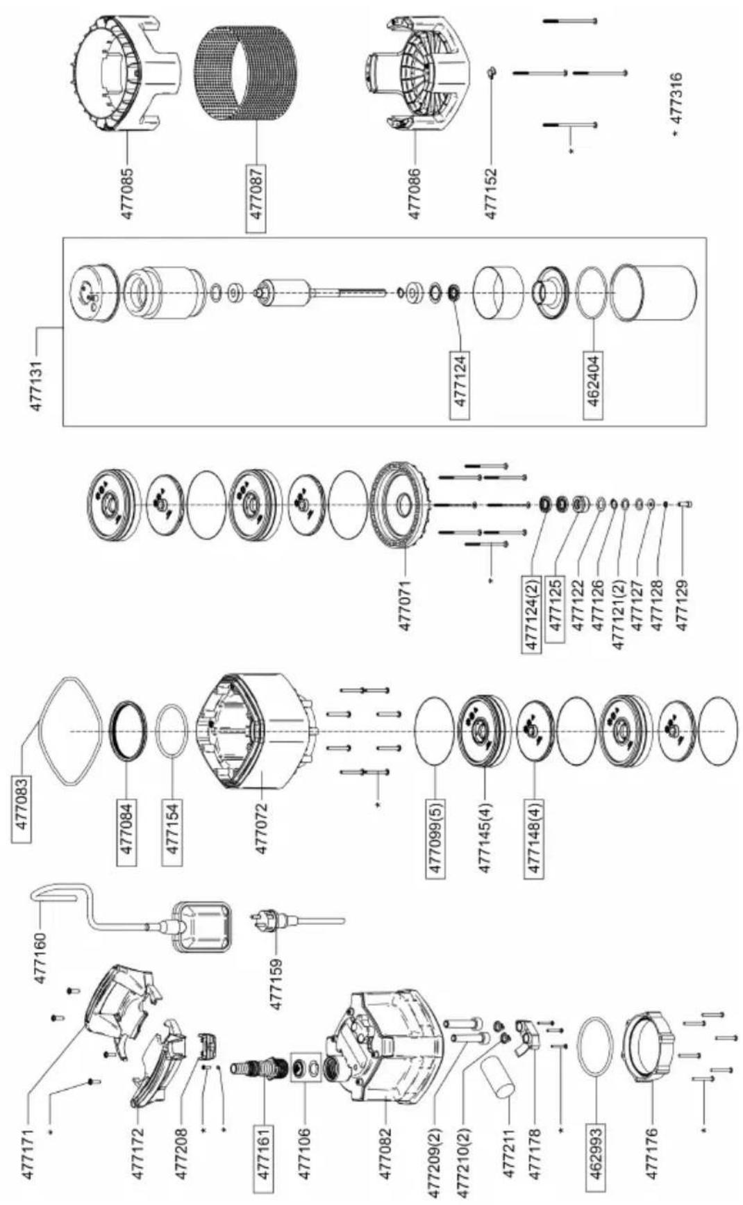
DIVE 5500-3 / DIVE 6300-4
line
| m³/h | DIVE 5500-3 Hm | DIVE 6300-4 Hm | |------|----------------|----------------| | 12 | 28 | 38 | | 30 | 25 | 35 | | 47 | 22 | 32 | | 58 | 19 | 29 | | 72 | 16 | 25 | | 85 | 11 | 20 | | 97 | 6 | 15 | | 105 | 3 | 10 |TECHNISCHE DATEN
 | DIVE 5500/3Art. Nr.113 036 | DIVE 6300/4Art. Nr.113 037 |
 | 800 W 1000 W | |
 | 230 V, 50 Hz 230 V, 50 Hz | |
 | IP X8 IP X8 | |
 | 30 m 40 m | |
 | ca. 7 m ca. 7 m | |
 | ca. 5500 l/h ca. 6300 l/h | |
 | 3 | 4 |
 | 0,5 mm 0,5 mm | |
 | ca. 400 mmca. 200 mm | ca. 400 mmca. 200 mm |
 | ca. 35 °C ca. 35 °C | |
 | 9,5 kg 10 kg | |
 | 10 m 10 m |
Wolfgang Hergeth Managing Director

2015
GARANTIE
Scope of delivery.... 11
Safety instructions....11
Assembly....11
Startup....11
Maintenance and care.... 12
Storage....12
Disposal....12
Troubleshooting....13
EU declaration of conformity....14
Warranty.... 14
PRODUCT DESCRIPTION
This documentation describes various different models of immersion pumps. Identify your model using the identification plate.
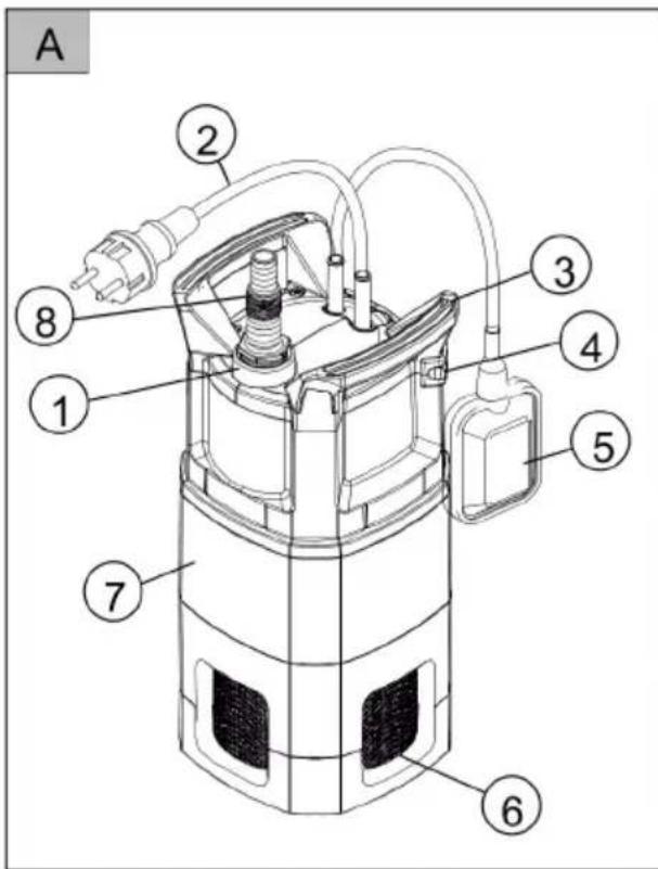
Product overview
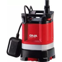
1 Pump outlet
2 Connection cable
3 Carrying handle
4 Cable clamp
5 Float switch
6 Inlet strainer
7 Pump housing
8 Multi-size nipple
Function of the pump
The submersible pump sucks the liquid to be pumped into the pump through the inlet strainer (8) and pumps it out at the outlet.
Designated use
The submersible pump is designed for home use in your house or garden. Please observe the technical data given in the instructions before putting the pump into operation.
ABOUT THIS HANDBOOK
Read this documentation before starting up the machine. This is a precondition for safe working and flawless operation.
- Observe the safety warnings in this documentation and on the product.
This documentation is a permanent integral part of the product described and must be passed on to the new owner if the product is sold.
Explanation of symbols

CAUTION!
Following these safety warnings carefully can prevent personal injury and/or material damage.

Special instructions for greater ease of understanding and improved handling.
Your submersible pump has been designed for use in the following applications:
■ emptying containers or pumping liquid from one container into another,
- pumping water from wells, cisterns and other water tanks
■ operating irrigation systems and lawn sprinklers
■ for the domestic water supply.
The submersible pump is designed to pump only the following liquids:
clear water
rain water
■ chlorinated water (pool water)
■ water for domestic use.
Possible misuse
Your submersible pump is not intended for permanent operation. The pump may not be used to pump the following liquids:
drinking water
salt water
■ beverages or liquid foods
corrosives or chemicals
■ acids or combustible, explosive or gasforming liquids
■ liquids with a temperature above 35 °C
■ sandy water or water containing abrasives
■ waste water containing textile or paper particles
SCOPE OF DELIVERY
Thermal protection
Your submersible pump is equipped with a thermal protection switch which automatically switches off the pump in case of overheating. The pump will remain off until it has cooled down. After about 15 - 20 minutes, the pump will automatically switch on.
SAFETY INSTRUCTIONS

CAUTION!
Risk of injury!
Use the machine and the extension cable only in perfect working order. Damaged equipment may not be operated.
Do not disable safety and protective devices!
Children, or people who are not familiar with the operating instructions, are not allowed to use the machine.
- Never lift, transport or suspend the unit using the connection cable.
■ Unilateral modifications or conversions of the unit are prohibited.
Electrical safety

CAUTION!
Danger when touching voltage conducting parts!
Disconnect the plug from the mains if the extension cable is damaged or severed! We recommend connecting a RCD (residual current operated device) having a nominal residual current of < 30 mA.
The pump may not be operated while people are in the pool or pond.
The house mains voltage must agree with the details quoted in the technical data, do not use any other supply voltage.
The unit must only be operated with an electrical installation in accordance with DIN/VDE 0100, Part 737, 738 and 702. Protection must be provided by a 10 A line protection switch and a RCCD (residual current operated device) having a nominal residual current of 10/30 mA.
Use only extension cables that are suitable for use outdoors - minimum cross-section 1.5 mm ^2 . Cable drums should always be unrolled completely.
■ Damaged or brittle extension cables must not be used.
⇒ Check the condition of your extension cable each time you start to use the equipment.
ASSEMBLY
Mounting the pressure line

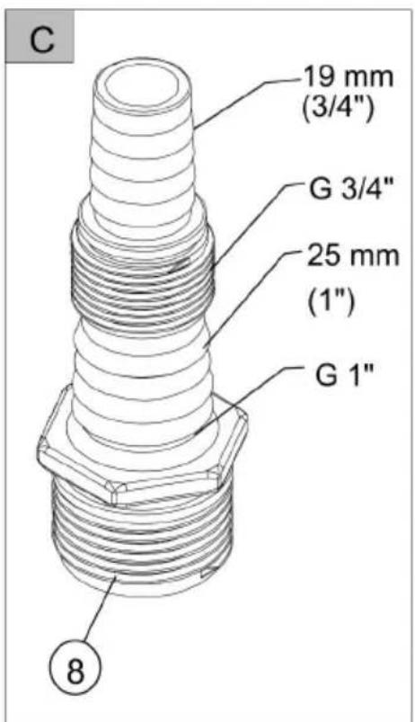
You can cut off the tip of the multi-size nipple to fit the diameter of the hose you are using. Using a hose with the largest possible diameter will greatly improve the performance of the pump.
1 Screw the multi-size nipple (10) into the pump outlet.
2 Attach a hose to the multi-size nipple.
3 Fix the connection cable (3) with cable ties to the pressure hose.
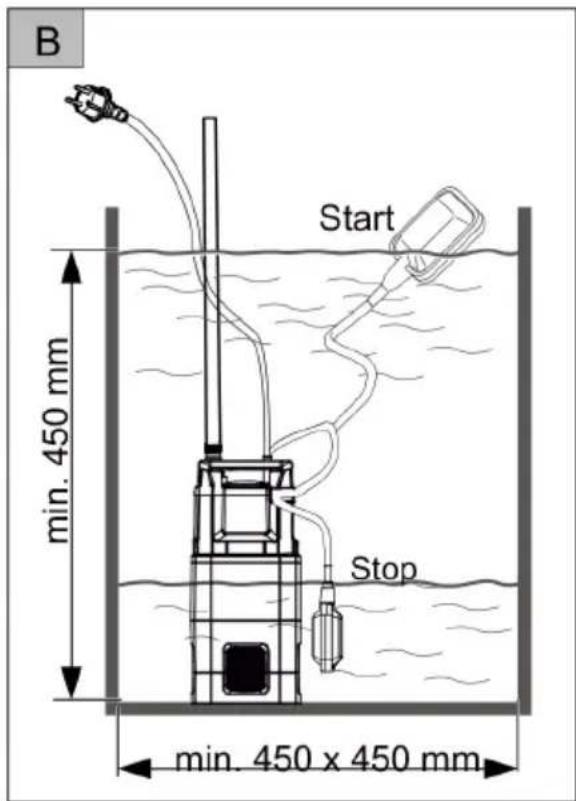
4 To submerse the pump into a well or cistern, attach a rope to the rope bracket (4) provided for this purpose.
5 Uncoil the electric cable completely.
6 Plug the pump into the socket. As soon as Adjusting the cut-in and cut-off levels the pump has reached the cut-in (= START) level, the float switch will automatically switch the pump on. When the liquid has fallen below the cut-off (= STOP) level, the pump will automatically switch off, see technical data.
STARTUP
Safety

CAUTION!
Take suitable measures, e.g. installation of an alarm or a back-up pump, to ensure that flooding will not occur if the pump should malfunction.

CAUTION!
When placing the pump in the liquid, make sure to let it down slowly. You may need to tilt the pump slightly so that air trapped in the body is released. Set the pump on the bottom so that it cannot fall over. If the bottom should be sandy or muddy or rocky and uneven, place the pump on a suitable hard, flat surface or suspend it from a rope attached to a secure object. Make sure to leave adequate room between the pump and the bottom so that it cannot suck up solid matter.

CAUTION!
Make sure that the pump does not suck in solid matter. Sand or other abrasive particles suspended in the liquid will lead to increased wear and tear and may impact the performance of your pump. Before lowering the pump into a well or a cistern, attach a rope to the handle. When placing the pump inside a cistern, make sure that the shaft is large enough for the pump to fit. For min. shaft dimensions, see Figure B.

CAUTION!
Place a cover over the cistern so that no one will fall in.

CAUTION!
When switching the pump on again after removing it from a cistern, make sure that the pressure hose is completely empty otherwise the pump will not automatically vent and it could be damaged.

CAUTION!
Make sure that the pump does not run with a blocked or closed pressure hose.

The pump has a non-return valve (2) on the pump output that prevents the pressure hose from emptying the pump every time it is at a standstill.
Adjusting the cut-in and cut-off levels
The float switch cable is attached to the pump housing. You can adjust the cut-in = START and cut-off = STOP levels for operation by simply
changing the height of the switch as desired. Recommended length of the float switch cable is approx. 120 mm.

CAUTION!
While pumping to the minimum submerged depth, make sure to keep the pump under observation and turn it off by pulling the plug when the minimum submerged depth has been reached to prevent the pump from sucking in air, as this may damage your pump.

If the level of the remaining water drops below the minimum submersed depth, the pump will suck in air. Before using the pump again to drain liquid, the air trapped in the pump will have to be vented (see Setting up and Operating the Pump).
Switching off the Pump
1 To switch off the pump, just pull the plug of the electric cable from the socket.
MAINTENANCE AND CARE
- Disconnect the machine from the mains power supply before commencing assembly and maintenance work.
Cleaning the pump

After conveying chlorine-containing swimming pool water or fluids that leave a residue, the pump must be flushed out with clear water.
- Clean the suction slots on the suction foot if necessary with clear water.
STORAGE

In the event of a risk of frost, the system must be drained completely.
DISPOSAL
Do not dispose of worn-out machines or spent batteries (including rechargeable batteries) in domestic waste!
The packaging, machine and accessories are made from recyclable materials and must be disposed of accordingly.
TROUBLESHOOTING
Help in case of malfunctions

CAUTION!
Disconnect the mains plug before any fault rectification work! Faults in the electrical system must be rectified by a qualified electrician.
| Malfunction Possible cause Solution | ||
| Motor does not run. | Impeller blocked. Remove dirt in the suction area. | Clean with a suitable tool through the opening at the back of the motor housing. |
| Thermal protection switch has switched off. | Wait until the thermal protection switch on the immersion pump switches on again. Take note of the maximum temperature of the conveying medium. Have the immersion pump inspected. | |
| No mains power. Check the fuses, have the power supply checked by a qualified electrician. | ||
| Float switch does not switch off when the water level rises. | Send the immersion pump to an AL-KO service facility. | |
| Pump running but does not feed. | Air in pump housing. Vent the immersion pump by holding it at an angle. | |
| Blockage on the suction side. Remove dirt in the suction area. | ||
| Pressure line closed off. Open the pressure line. | ||
| Pressure hose kinked. Extend the pressure hose. | ||
| Feed rate too low | Hose diameter too small. Use a bigger pressure hose. | |
| Blockage on the suction side. Remove dirt in the suction area. | ||
| Feed head to high. Observe max. feed head, see technical data! | ||

If the faults cannot be rectified, please contact our customer service department.
EU DECLARATION OF CONFORMITY
We hereby declare that this product, in the version brought into circulation by us, complies with the requirements of the harmonised EU guidelines, EU safety standards and the product-specific standards.
Product Type Manufacturer
| Immersion pump, electrical | DIVE 5500/3 | AL-KO Geräte GmbH |
| DIVE 6300/4 | Ichenhauser Str. 14 | |
| Serial number | D-89359 Kötz | |
| G3023025 |
Duly authorised person EU guidelines Harmonised standards
| Andreas Hedrich | 2014/35/EU | EN 60335-1:2012 |
| Ichenhauser Str. 14 | 2014/30/EU | EN 60335-2-41:2012 |
| D-89359 Kötz | 2011/65/EU | EN 62233:2008 |
We will address claims for any defects in materials and workmanship during the statutory period of limitation by means of repairs or replacements of our choice. The period of limitation is governed by the laws of the country in which the machine was purchased.
Our warranty applies only if:
The machine has been properly handled
The operating instructions have been adhered to
■ Original replacement parts have been used
The warranty is no longer in effect if:
■ Efforts have been made to repair the machine
■ Technical modifications have been made to the machine
The machine has not been used for its intended purpose
The warranty does not cover:
■ Damage to paint work through normal use
Parts subject to wear as indicated in the replacement parts list with a box [xxx xxx (x)]
Internal combustion engines – separate warranty conditions of the respective engine manufacturer apply
The warranty period begins with the purchase by the first buyer. The warranty period begins on the date that appears on the original purchase receipt. In the event of a warranty claim, please your contact supplier or the nearest authorised customer service centre with this warranty declaration and the purchase receipt in hand. This warranty does not affect the legal warranty claims by the purchaser against the seller.
ORIGINELE HANDLEIDING
Inhoudsopgave
Over dit handboek....15
INFORMATIONS SUR CE MANUEL
DÉCLARATION DE CONFORMITÉ CE
DEKLARACJA ZGODNOŚCI WE
VEDLIKEHOLD OG PLEIE
Wolfgang Hergeth Managing Director

2015
ГАРАНТИЯ
Wolfgang Hergeth Managing Director
2015
ГАРАНТИЯ
DIVE 6300-4
Art.Nr. 113 037
| Country | Company | Telephone | Fax |
| A | AL-KO KOBER Ges.m.b.H. | (+43)3578/2515-100 | (+43)3578/2515-31 |
| AUS | AL-KO INTERNATIONAL Pty. Ltd. | (+61)3/9767-3700 | (+61)3/9767-3799 |
| B / L | Eurogarden NV | (+32)16/805427 | (+32)16/805425 |
| BG | Valerii S&M Group SJ | (+359)2 942 34 02 | (+359)2 942 34 10 |
| CH | AL-KO KOBER AG | (+41)56/418-31 53 | (+41)56/4183160 |
| CZ | AL-KO KOBER Spol. S.R.O. | (+420)382/210381 | (+420)382/212782 |
| D | AL-KO GERÄTE GmbH | (+49)8221/203-0 | (+49)8221/97-8199 |
| DK | AL-KO GINGE A/S | (+45)98821000 | (+45)98825454 |
| EST/LT/LV | SIA AL-KO KOBER | (+371)67/627-326 | ((+371)67/807-018 |
| F | AL-KO S.A.S. | (+33)3/8576-3500 | (+33)3/8576-3581 |
| GB | Rochford Garden Machinery Ltd. | (+44)1963/828050 | (+44)1963/828052 |
| H | AL-KO KFT | (+36)29/5370-50 | (+36)29/5370-51 |
| HR | Brun.ko.-prom d.o.o. | (+385)1 3096 567 | (+385)1 3096 567 |
| I | AL-KO KOBER GmbH / SRL | (+39)039/9329-311 | (+39)039/9329-390 |
| IN | AGRO-COMMERCIAL | (+91)3322874206 | (+91)3322874139 |
| IQ | Avro Gulistan Com | (+946)750 450 80 64 | |
| IRL | Cyril Johnston & Co. Ltd. | (+44)2890813121 | (+44)2890914220 |
| LY | ASHOFAN FOR AGRICULT. ACC. | (+218)512660209 | (+218)512660209 |
| MA | BADRA Sarl | (+212)022447128 | (+212)022447130 |
| MK | Techno Geneks | (+389)2 2551801 | (+389)2 2520175 |
| N | AL-KO GINGE A/S | (+47)64/86-2550 | (+47)64/86-2554 |
| NL | O.DE LEEUW GROENTECHNIEK | (+31)38/444 6160 | (+31)38/444 6358 |
| PL | AL-KO KOBER Sp. z.o.o. | (+48)61/816-1925 | (+48)61/816-1980 |
| RO | SC PECEF TEHNICA SRL | (+40)344 40 30 30 | (+40)244 51 44 86 |
| RUS | OOO AL-KO KOBER | (+7)499/16708-42 | (+7)499/96600-00 |
| RUS | ZAO AL-KO St. Petersburg GmbH | (+7)812/446-1084 | (+7)812/446-1084 |
| S | GINGE Svenska AB | (+46)31/57-3580 | (+46)31/57-5620 |
| SK | AL-KO KOBER Slovakia Spol. S.R.O. | (+421)2/4564-8267 | (+421)2/4564-8117 |
| SLO | Darko Opara s.p. | (+386)1 722 58 50 | (+386)1 722 58 51 |
| SRB | Agromarket d.o.o. | (+381)34 308 000 | (+381)34 308 16 |
| TR | ZIMAS A.S. | (+90)232 4580586 | (+90)232 4572697 |
| UA | TOV AL-KO KOBER | (+380)44/392-07-08 | (+380)44/392-07-09 |

- Inhaltsverzeichnis
- GARANTIE
- PRODUCT DESCRIPTION
- Product overview
- Function of the pump
- Designated use
- ABOUT THIS HANDBOOK
- Explanation of symbols
- CAUTION!
- Possible misuse
- SCOPE OF DELIVERY
- Thermal protection
- SAFETY INSTRUCTIONS
- Risk of injury!
- Electrical safety
- Danger when touching voltage conducting parts!
- ASSEMBLY
- Mounting the pressure line
- STARTUP
- Safety
- Adjusting the cut-in and cut-off levels
- Switching off the Pump
- MAINTENANCE AND CARE
- Cleaning the pump
- STORAGE
- DISPOSAL
- TROUBLESHOOTING
- Help in case of malfunctions
- EU DECLARATION OF CONFORMITY
- Our warranty applies only if:
- The warranty is no longer in effect if:
- The warranty does not cover:
- ORIGINELE HANDLEIDING
- Inhoudsopgave
- INFORMATIONS SUR CE MANUEL
- DÉCLARATION DE CONFORMITÉ CE
- DEKLARACJA ZGODNOŚCI WE
- VEDLIKEHOLD OG PLEIE
- ГАРАНТИЯ
- DIVE 6300-4
Brand : AL-KO
Model : Dive 55003
Category : Pump