
ZIBHA1500D - Drill Zipper - Free user manual and instructions
Find the device manual for free ZIBHA1500D Zipper in PDF.

| Product type | Hammer drill / rotary hammer |
| Brand | Zipper |
| Model | ZIBHA1500D |
| Motor power | 1500 W |
| Voltage / Frequency | 230 V / 50 Hz |
| No-load speed | 880 min⁻¹ |
| Impact rate | 4350 blows/min |
| Max. drill capacity (concrete) | 32 mm |
| Max. chisel capacity | 17 mm |
| Tool holder | SDS-plus (10 mm) |
| Weight | 4.9 kg |
| Protection class | II (double insulation) |
| Sound pressure level | 93.5 dB(A) (uncertainty K=3 dB) |
| Sound power level | 104.7 dB(A) (uncertainty K=3 dB) |
| Vibration (drilling concrete, main handle) | 5.679 m/s² (uncertainty K=1.5) |
| Vibration (chiseling at full power, auxiliary handle) | 18.214 m/s² (uncertainty K=1.5) |
| Functions | Drilling, hammer drilling, chiseling, chiseling with rotation |
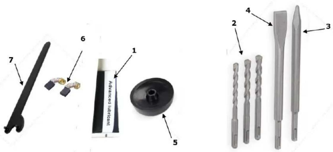
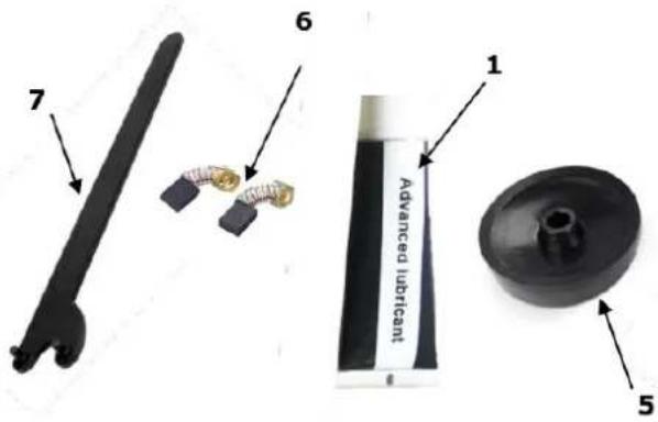
| Delivery contents | Drill bits (∅8, 10, 12 mm), pointed chisel, flat chisel, auxiliary handle, 2-hole key, grease, carbon brushes, dust cap |
| Maintenance | Clean after each use, lubricate every 100 h, replace carbon brushes if necessary |
| Safety | Automatic shutdown in case of overload, double insulation, SDS-plus lock, protection against accidental restarts |
| Operating conditions | Temperature: +5°C to +40°C, max. humidity 70% |
| Warranty | 2 years (DIY use), 1 year (professional use) |
Frequently Asked Questions - ZIBHA1500D Zipper
User questions about ZIBHA1500D Zipper
0 question about this device. Answer the ones you know or ask your own.
Ask a new question about this device
Download the instructions for your Drill in PDF format for free! Find your manual ZIBHA1500D - Zipper and take your electronic device back in hand. On this page are published all the documents necessary for the use of your device. ZIBHA1500D by Zipper.
USER MANUAL ZIBHA1500D Zipper
natural_image
Green and black ZIPPER 150D drill press tool with helical head and handle (no visible text or symbols on device body)ZI-BHA1500D
EAN: 9120039232652
CE

1 INHALT / INDEX
1 INHALT / INDEX 2
11.1 Intended Use....17
11.2 Security instructions .... 18
11.3 Remaining risk factors.... 19
12 OPERATION 19
12.1 Operation instructions.... 19
12.2 Operation 20
12.2.1 Insert drill or chisel 20
12.2.2 Remove drill or chisel 20
12.2.3 Adjust auxiliary handle 20
12.2.4 Drilling....20
12.2.5 Chiselling 20
12.2.6 Switch on / off 20
13 WARTUNG 21
13.1 Maintenance plan 21
13.2 Cleaning 21
13.3 Disposal....21
14 TROUBLE SHOOTING 21
15 PREFACE (FR) 22
16 TECHNIQUE 23
16.1 Composants....23
EN CE-CONFORM: This product complies with EC-directives
EN READ THE MANUAL! Read the user and maintenance manual carefully and get familiar with the controls in order to use the machine correctly and to avoid injuries and machine defects.
EN ATTENTION! Ignoring the safety signs and warnings applied on the machine as well as ignoring the security and operating instructions can cause serious injuries and even lead to death.
EN Protective clothing!
FR Vêtement de protection!
EN Stop and pull out the power plug before any break and engine maintenance!
EN Operation with jewelry forbidden!
EN Operation with tie forbidden!
EN Operation with long hair forbidden!
EN Warning of rotating parts!
EN Protect from moisture!
EN Protection class II!
FR Protection classe II!
SL Zaščitni razred II!
natural_image
Illustration of four different types of industrial cutting tools or drill bit designs, labeled 2 to 4 (no text or symbols on the tools themselves)natural_image
Mechanical assembly diagram showing a worm-like device with labeled component '2' (no text or symbols beyond label)natural_image
Mechanical assembly diagram showing a drill bit and screw mechanism (no text or labels)This manual contains important information and advice for the correct and safe use and maintenance of the drill hammer ZI-BHA1500D.
Following the usual commercial name of the device (see cover) is substituted in this manual with the name "machine".
The manual is part of the machine and may not be stored separately. Read it profoundly before first use of the machine and keep it for later reference. When the machine is handed to other persons always put the manual to the machine.
Please follow the security instructions!
Please read the entire manual, to prevent misunderstandings, machine damage or even injuries!

Due to continuous development of our products illustrations, pictures might differ slightly.
If you however find errors in this manual, please inform us.
Technical changes excepted!
Copyright law
© 2016
This manual is protected by copyright law – all rights reserved. Especially the reprinting as well as the translation and depiction of pictures will be prosecuted by law. Court of jurisdiction is the Landesgericht Linz or the competent court for 4707 Schlüsslberg, AUSTRIA.
Customer Support
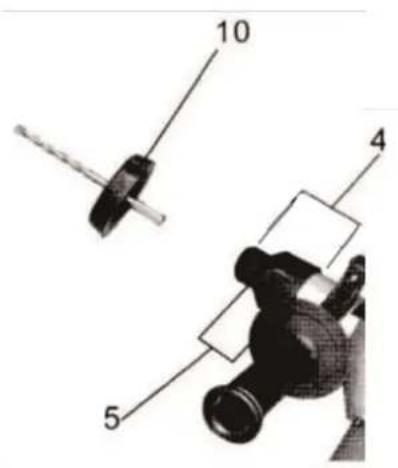
| 1 | Switch (drilling/hammer drilling) | 7 | Auxiliary handle |
| 2 | On-Off-switch | 8 | Lubrication point |
| 3 | Switch (drilling/hammer) | 9 | Motor |
| 4 | Tool mount (SDS-plus) | 10 | Dust protection cap |
| 5 | Locking sleeve |
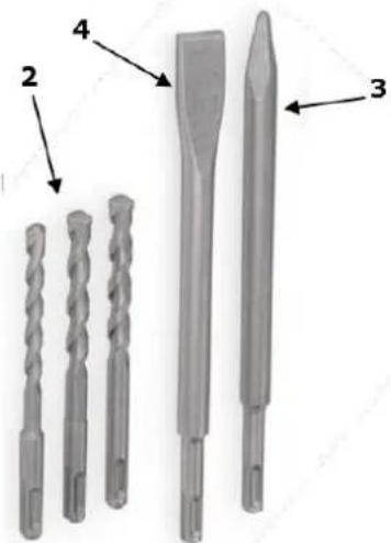
10.2 Delivery content
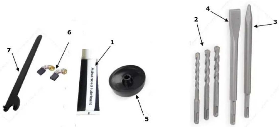
| 1 | Grease | 5 | Dust protection cap |
| 2 | Drill ( ∅ 8mm, 10mm, 12mm) | 6 | Carbon brushes |
| 3 | Pointed chisel | 7 | 2-hole-spanner |
| 4 | Flat chisel |
10.3 Technical details
| Voltage | 230 V / 50 Hz |
| Motor power | 1500 W |
| No-load speed | 880 min ^-1 |
| Hits | 4350 / min |
| Max. chisel capacity | ∅ 17mm |
| Max. drill capacity | ∅ 32mm |
| SDS-plus | 10 mm |
| Weight | 4,9 kg |
| Sound-power level LWA | 104,7 dB(A) bei K: 3dB(A) |
| Sound-pressure level LPA | 93,5 dB(A) bei K: 3dB(A) |
| Protection class | II |
10.3.1 Vibration
| Vibration emission valueUncertainly K=1,5 m/s2 | |||
| Drilling in concrete | Main handle | a_h,HD = 5,479 m/s^2 | |
| Auxiliary handle | a_h,HD = 10,901 m/s^2 | ||
| Chiseling | No load | Main handle | a_h,NL = 7,104 m/s^2 |
| Auxiliary handle | a_h,NL = 7,322 m/s^2 | ||
| Full load | Main handle | a_h,CH = 11,900 m/s^2 | |
| Auxiliary handle | a_h,CH = 18,214 m/s^2 | ||
| Equivalent value | Main handle | a_h,Cheq = 11,094 m/s^2 | |
| Auxiliary handle | a_h,Cheq = 16,8847 m/s^2 | ||
ATTENTI ON
The vibration emission during actual use of the power tool can differ from the declared total value depending on the ways in which the tool is use!
11 SAFETY
11.1 Intended Use
The machine must only be used for its intended purpose! Any other use is deemed to be a case of misuse.
To use the machine properly you must also observe and follow all safety regulations, the assembly instructions, operating and maintenance instructions lay down in this manual.
All people who use and service the machine have to be acquainted with this manual and must be informed about the machine's potential hazards.
It is also imperative to observe the accident prevention regulations in force in your area.
The same applies for the general rules of occupational health and safety.
The machine is used for:
Hammer drilling in concrete, brick and stone as well as for chiselling work.
Drilling without impact in wood, metal, ceramic and plastic.
Any manipulation of the machine or its parts is a misuse, in this case ZIPPER-MASCHINEN and its sales partners cannot be made liable for ANY direct or indirect damage.

WARNING
- Use only drills and chisels allowable for this machine!
- Never use a damaged drill or chisel!
- Use the machine never with defective or without mounted guard HIGHEST RISK OF INJURY!
Ambient conditions
The machine may be operated:
humidity
max. 70%
temperature
+5^ to +40^ (+41^ to +104^)
The machine shall not be operated in areas exposed to increased fire or explosion hazard.
Prohibited use
• The operation of the machine outside the stated technical limits described in this manual is forbidden.
• The use of the machine not according with the required dimensions is forbidden.
• The use of the machine not being suitable for the use of the machine and not being certified is forbidden.
- Any manipulation of the machine and parts is forbidden.
• The use of the machine for any purposes other than described in this manual is forbidden.
• The unattended operation on the machine during the working process is forbidden!
• It is not allowed to leave the immediate work area during the work is being performed.
11.2 Security instructions
Missing or non-readable security stickers have to be replaced immediately!
The locally applicable laws and regulations may specify the minimum age of the operator and limit the use of this machine!
To avoid malfunction, machine defects and injuries, read the following security instructions!


- Keep your work area dry and tidy! An untidy work area may cause accidents. Avoid slippery floor.
• Make sure the work area is lighted sufficiently - Do not overload the machine
- Provide good stability and keep balance all times
- Avoid abnormal working postures! Make sure you stand squarely and keep balance at all times.
- Keep away from the running drill!
• Always stay focused when working. Reduce distortion sources in your working environment. The operation of the machine when being tired, as well as under the influence of alcohol, drugs or concentration influencing medicaments is forbidden. - Respectively trained people only and only one person shall operate the machine.
- Do not allow other people, particularly children, to touch the machine or the cable. Keep them away from your work area.
• Make your workshop childproof.
• Make sure there is nobody present in the dangerous area. The minimum safety distance is 2m - Wear suitable work clothes! Do not wear loose clothing or jewellery as they might get caught in moving parts and cause severe accidents! Wear a hair net if you have long hair.
- Use personal safety equipment: safety gloves, dust musk, ear protectors and safety goggles when working with the machine.
- Never leave the machine running unattended! Before leaving the working area switch the machine off and wait until the machine stops.
• Always disconnect the machine prior to any actions performed at the machine. - Avoid unintentional starting
- Do not use the machine with damaged switch
- The plug of an electrical tool must strictly correspond to the socket. Do not use any adapters together with earthed electric tools
• Each time you work with an electrically operated machine, caution is advised! There is a risk of electric shock, fire, cutting injury; - Protect the machine from dampness (causing a short circuit)
- Use power tools and machines never in the vicinity of flammable liquids and gases (danger of explosion)
- Check the cable regularly for damage
- When working with the machine outdoors, use extension cables suitable for outdoor use
- Do not use the cable to carry the machine or to fix the work piece
- Protect the cable from heat, oil and sharp edges
- Avoid body contact with earthed
- Before starting the machine remove any adjusting wrenches and screwdrivers
- Rotating parts can cause severe cut injuries
- Keep the drills sharp and clean, so they get stuck less often and are easier to guide
- Keep any machine that is not being used out of reach of children

11.3 Remaining risk factors

WARNING
It is important to ensure that each machine has remaining risks. In the execution of all work (even the simplest) greatest attention is required. A safe working depends on you!
Even if the machine is used as required it is still impossible to eliminate certain residual risk factors totally. The following hazards may arise in connection with the machine's construction and design:
• Risk of injury to the hands / fingers by the rotating tool and tool mount during operation.
- Risk of injury due to sharp edges of the workpiece, especially in non-fixed with a suitable tool / device workpiece.
- Risk of injury: hair and loose clothing, etc. can be captured and wound up! Safety regulations must be observed with regard to clothing.
- Risk of injury due to contacting with live electrical components.
• Risk of injury due to dust emissions, treated with harmful agents workpieces
• Risk of injury to the hearing by prolonged labor without hearing protection
• Risk of injury to the eye by flying debris, even with safety goggles.
• Health damage caused by hand-arm vibrations if the equipment is used over a prolonged period or is not properly guided and maintained.
These risk factors can be minimized through obeying all security and operation instructions, proper machine maintenance, proficient and appropriate operation by persons with technical knowledge and experience.
12 OPERATION
Device to be operated in a perfect state only. Inspect the device visually every time it is to be used. Check in particular the safety equipment, electrical controls, electric cables and screwed connection for damage and if tightened properly. Replace any damaged parts before operating the device.
12.1 Operation instructions

WAR NING
Perform all machine settings with the machine being disconnected from the power supply!

ATTENTION
Excessive pressure may cause material damage!
- When drilling with the drill only slight pressure is required
- Too much pressure unnecessarily overload the motor and cause damage!

NOT ICE
- Use auxiliary handles supplied with the tool Loss of control can cause personal injury
- Hold the machine by insulated gripping surface
The contact with a live wire can cause electric shock
- Prior to cutting into walls, ceilings or floors, ensure there are no electric cables or conduits inside.
- Checking the mains, whether they comply with the relevant national standards and guidelines (especially Assemblies for Construction Sites)
- Use only clean working tool. Lightly lubricate the drill- or chisel shank before use with a grease.
12.2 Operation
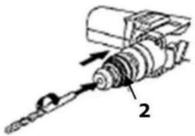
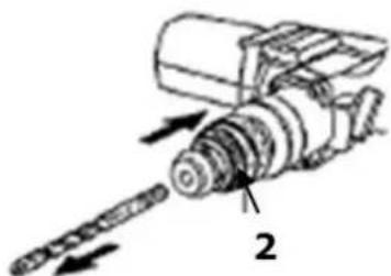
12.2.1 Insert drill or chisel
- Pull locking sleeve (2) back and hold it fast.
- Push and at the same time turn the chisel or a drill into the tool mount as far as it stops and release the locking sleeve.
- Ensure firm locking by pulling firmly on the work tool.
natural_image
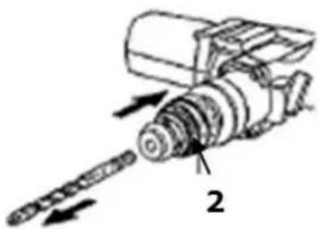
Mechanical assembly diagram showing a worm-like device with labeled component '2' (no text or symbols beyond label)12.2.2 Remove drill or chisel
- Pull back the locking sleeve (2) hold it fast, remove the work tool and release the locking sleeve.
- Clean the work tool and rub it over with a small amount of machine grease.
natural_image
Mechanical assembly diagram showing a worm-like device with directional arrows indicating movement (no text or symbols)12.2.3 Adjust auxiliary handle
- Release the fixture of the auxiliary handle (7) (turning two or three times anticlockwise)
- Turn the auxiliary handle to the desired position
- Fix the auxiliary handle again by turning clockwise
12.2.4 Drilling
Without impact:
1 Switch (drilling / hammer drilling)
With impact:
1 Switch (drilling / hammer drilling)

When working overhead, push dust protection cap over the drill. Empty as often as required and push over the drill again.
12.2.5 Chiselling
Chiselling:
3 Switch (drilling/hammer)
Chiselling and drilling:
3 Switch (drilling/hammer)

Flat chisel (4)
Flat chisel is used for finer chiselling work such as loosing ceramic tiles, removal of the adhesive, etc.
Pointed chisel (3)
Pointed chisel is best used for coarse chiselling such as breaking up cement or concrete flagstones, walls, etc.
12.2.6 Switch on / off
• To switch on, press On/Off-switch (2)
• The machine is switched on for as long as On/Off-switch is depressed.
13 WARTUNG

ATTENTI ON
Perform all maintenance machine settings with the machine being disconnected from the power supply!
Serious injury due to unintentional or automatic activation of the machine!

The machine does not require extensive maintenance. If malfunctions and defects occur, let it be serviced by trained persons only. Before first operation as well as later on every 100 operation hours you should lubricate all connecting parts (if required, remove beforehand with a brush all swarfs and dust).
NOTICE
Clean your machine regularly after every usage – it prolongs the machines lifespan and is a pre-requisite for a safe working environment.
Repair jobs shall be performed by respectively trained professionals only!
Check regularly the condition of the security stickers. Replace them if required.
Check regularly the condition of the machine. Store the machine in a closed, dry location.
13.1 Maintenance plan
| Inspections for the maintenance of the machine | |
| Loose or missing screws | Daily before starting |
| Damage to any part | Daily before starting |
| Clean the machine | Daily before starting |
| Check tool mount to wear of | Every 100 working hours |
13.2 Cleaning
After each workshift the machine has to be cleaned. Remove chips etc. with a suitable tool. Do not remove them by hand (cutting injury!). Remove dust as well.

NOTICE
The usage of certain solutions containing ingredients damaging metal surfaces as well as the use of scrubbing agents will damage the machine surface!
Clean the machine surface with a wet cloth soaked in a mild solution
13.3 Disposal
Do not dispose the machine in residual waste. Contact your local authorities for information regarding the available disposal options. When you buy at your local dealer for a replacement unit, the latter is obliged to exchange your old.
14 TROUBLE SHOOTING
BEFORE YOU START WORKING FOR THE ELIMINATION OF DEFECTS, DISCONNECT THE MACHINE FROM THE POWER SUPPLY.
| Trouble | Possible cause | Solution |
| Machine stops or will not start | Saw unpluggedCord damagedOverload tripped | Check all power connectionsChange cableAllow motor to cool and reset by pushing off switch |
| Impact system blocks | High fat friction due to low temperaturesMoving parts are blocked | Warm up the machine in a warm environmentChange damaged parts |
| Drill stucks | Too much boring dust in the boreholeDisruptive reinforced steel | Clean the drillFix new borehole |
MANY POTENTIAL SOURCES OF ERROR CAN BE CLEARED BY THE EXPERTLY CONNECTION TO THE ELECTRICITY GRID.

NOTICE
Should you in necessary repairs not able to properly to perform or you have not the prescribed training for it always attract a workshop to fix the problem.
15 PREFACE (FR)
Cher client!
natural_image
Mechanical assembly diagram showing a tool interacting with a cylindrical component (no text or symbols)natural_image
Mechanical assembly diagram showing a worm-like device with labeled component '2' (no text or symbols beyond label)24.2.2 Odstranjevanje svedra ali dleta
- Zaporno pušo (2) potegnite nazaj in jo trdno držite. Izvlecite orodje in nato zaporno pušo previdno spustite, da zdrsne v začetni položaj.
- Očistite orodje in ga konzervirajte z malo strojnega maziva.
natural_image
Mechanical assembly diagram showing a drill bit and screw mechanism (no text or labels)| 1 | Prekidač za biranje (bušenje/udarno bušenje) | 7 | Dodatna drška |
| 2 | Prekidač za uključivanje/isključivanje | 8 | Rupa za podmazivanje |
| 3 | Prekidač za biranje (bušenje/rad čekićem) | 9 | Motor |
| 4 | Prihvat alata (SDS-plus) | 10 | Kapica za zaštitu od prašine |
| 5 | Čahura za fiksiranje |
28.2 Pribor
| 1 | Mast za podmazivanje | 5 | Kapica za zaštitu od prašine |
| 2 | Svrdlo ( ∅ 8mm, 10mm, 12mm) | 6 | Ugljene četkice |
| 3 | Šiljato dlijeto | 7 | Ključ s 2 rupe |
| 4 | Plosnato dlijeto |
natural_image
Mechanical assembly diagram showing a tool inserted into a cylindrical component with labeled parts (no text or symbols present)natural_image
Mechanical assembly diagram showing a worm-like device with directional arrows indicating movement (no text or symbols)| 1 | Prekidač za biranje (bušenje/udarno bušenje) | 7 | Dodatna drška |
| 2 | Prekidač za uključivanje/isključivanje | 8 | Rupa podmazivanje |
| 3 | Prekidač za biranje (bušenje/rad čekićem) | 9 | Motor |
| 4 | Prihvat alata (SDS-plus) | 10 | Kapica za zaštitu od prašine |
| 5 | Čahura za fiksiranje |
34.2 Pribor
| 1 | Mast za podmazivanje | 5 | Kapica za zaštitu od prašine |
| 2 | Burgija ( ∅ 8mm, 10mm, 12mm) | 6 | Ugljen četka |
| 3 | Špic | 7 | Ključ s 2 rupe |
| 4 | Sekač |
natural_image
Mechanical assembly diagram showing a worm-like device with labeled component '2' (no text or symbols beyond label)42.2.2 Rinmuovere punta o scapello
natural_image
Mechanical assembly diagram showing a worm-like device with directional arrows indicating movement (no text or symbols)42.2.3 Foratura
With original ZIPPER spare parts you use parts that are attuned to each other shorten the installation time and elongate your machines lifespan.
IMP OR TAN T
The installation of other than original spare parts voids the warranty!
So you always have to use original spare parts
When you place a spare parts order please use the service formular you can find in the last chapter of this manual. Always take a note of the machine type, spare parts number and partname. We recommend to copy the spare parts diagram and mark the spare part you need.
You find the order address in the preface of this operation manual.
| NO | Name | qty | NO | Name | qty |
| 1 | Rubber Head | 1 | 55 | small gear 10 teeth | 1 |
| 2 | Steel Ring 17.5x2 | 1 | 56 | Adjust washer 19x15x4.7 | 1 |
| 3 | Steel Frame | 1 | 57 | Bearing 6002 | 1 |
| 4 | Spring 30.2x1.8x76 | 1 | 58 | Adjust washer14.1x19x0.5 | 1 |
| 5 | seal lock Hex.Socket Hd.Bolt M5x22 | 4 | 59 | Steel ball | 8 |
| 6 | Spring Washer 5 | 8 | 60 | flat board gear 39 teeth | 1 |
| 7 | Flat washer 5 | 8 | 61 | fixed board | 1 |
| 8 | Cylinder case | 1 | 62 | Circlips for shaft 12.5x1 | 1 |
| 9 | oil Seal 35x51x6 | 1 | 63 | Friction flate | 1 |
| 10 | Circlips for shaft 35 | 4 | 64 | spring | 4 |
| 11 | Big Washer 5 | 1 | 65 | self-locking nut | 1 |
| 12 | Bearing 61907-RZ | 1 | 66 | bearing 627 | 1 |
| 13 | Steel ball 7.14 | 5 | 67 | Crankshaft | 1 |
| 14 | teleflex | 1 | 68 | Bearing 6003 | 1 |
| 15 | X-oil seal 19x30x2.5 | 1 | 69 | Washer 28.5x1 | 1 |
| 16 | O-ring 11x2 | 2 | 70 | Internal Retaining Ring 35 | 1 |
| 17 | Impact hammer | 1 | 71 | Circlips for shaft 17 | 1 |
| 18 | steel Ball Φ7.14 | 3 | 72 | Big gear | 1 |
| 19 | Cylinder | 1 | 73 | Spring 6.8X1.2X33 | 1 |
| 20 | Flat key 3x2.5x18 | 2 | 74 | Square Key 22x5x5 | 1 |
| 21 | Plastic Range Ring | 1 | 75 | Dome Pin 7x19 | 1 |
| 22 | Plastic Cylinder Case | 1 | 76 | oil bearing | 1 |
| 23 | Big Spring 37x3.5x76 | 1 | 77 | steel sleeve 22x26x9 | 1 |
| 24 | gear 34 teeth | 1 | 78 | pillar | 1 |
| 25 | Circlips for shaft 28x1.6 | 2 | 79 | ball 4 | 1 |
| 26 | O-ring 19x3.1 | 2 | 80 | middle cover | 1 |
| 27 | rammer | 1 | 81 | button | 1 |
| 28 | Washer 47 | 1 | 82 | bearing 6001 | 1 |
| 29 | Oil Bearing | 1 | 83 | Fan Guide | 1 |
| 30 | piston | 1 | 84 | Rotor | 1 |
| 31 | Piston Pin | 1 | 85 | Screw ST4.8x60 | 2 |
| 32 | Connecting Rod | 1 | 86 | Stator | 1 |
| 33 | steel sleeve | 1 | 87 | spring | 1 |
| 34 | Cross pan head self-drilling screw ST4.8X50 | 4 | 88 | Bearing 608 | 1 |
| 35 | Gear Box | 1 | 89 | Motor house | 1 |
| 36 | Oil cover | 1 | 90 | Brush cover | 2 |
| 37 | O-ring 31.5x2 | 1 | 91 | Brush house | 2 |
| 38 | Damping spring 10x1.5x26 | 2 | 92 | Brush | 2 |
| 39 | Damping washer | 1 | 93 | Back coer | 1 |
| 40 | Damping Board | 1 | 94 | seal lock hex.socket Hd.bold M8x50 | 1 |
| 41 | Damping Screw M8x35 | 2 | 95 | Right Handle | 1 |
| 42 | self-drilling screw st3.9x16 | 16 | 96 | Left handle | 1 |
| 43 | Gear Box Right Cover | 1 | 97 | hexagon lock Nut M8 | 1 |
| 44 | Dial the torsion spring | 1 | 98 | cable cover | 1 |
| 45 | Washer 12.1x18x0.5 | 1 | 99 | cable | 1 |
| 46 | Internal Retaining Ring 18 | 1 | 100 | capacitance | 1 |
| 47 | button | 1 | 101 | inductance | 1 |
| 48 | spring | 1 | 102 | switch | 1 |
| 49 | knob | 1 | 103 | cable plate | 1 |
| 50 | washer 4 | 1 | 104 | T-shape Nut M8 | 1 |
| 51 | washer 4 | 1 | 105 | bracket | 1 |
| 52 | Screw ST3.9x16 | 1 | 106 | Auxiliary Handle | 1 |
| 53 | Gear Box Left Cover | 1 | 107 | Hoop | 1 |
| 54 | oil seal 19x28x4.5 | 1 | |||
Company ZIPPER Maschinen GmbH grants for mechanical and electrical components a warranty period of 2 years for amateur use; and warranty period of 1 year for professional use, starting with the purchase of the final consumer. In case of defects during this period, which are not excluded by paragraph 3, ZIPPER will repair or replace the machine at its own discretion.
2.) Report:
In order to check the legitimacy of warranty claims, the final consumer must contact his dealer. The dealer has to report in written form the occurred defect to ZIPPER. If the warranty claim is legitimate, ZIPPER will pick up the defective machine from the dealer. Returned shippings by dealers which have not been coordinated with ZIPPER, will not be accepted and refused.
3.) Regulations:
a) Warranty claims will only be accepted, when a copy of the original invoice or cash voucher from the trading partner of ZIPPER is enclosed to the machine. The warranty claim expires if the accessories belonging to the machine are missing.
b) The warranty does not include free checking, maintenance, inspection or service works on the machine. Defects due to incorrect usage of the final consumer or his dealer will not be accepted as warranty claims either. Some examples: usage of wrong fuel, frost damages in water tanks, leaving fuel in the tank during the winter, etc.
c) Defects on wear parts are excluded, e.g. carbon brushes, collection bags, knives, cylinders, cutting blades, clutches, sealings, wheels, saw blades, splitting crosses, riving knives, riving knife extensions, hydraulic oils, oil/air/fuel filters, chains, spark plugs, sliding blocks, etc.
d) Also excluded are damages on the machine caused by incorrect or inappropriate usage, if it was used for a purpose which the machine is not supposed to, ignoring the user manual, force majeure, repairs or technical manipulations by not authorized workshops or by the customer himself, usage of non-original ZIPPER spare parts or accessories.
e) After inspection by our qualified personnel, resulted costs (like freight charges) and expenses for not legitimated warranty claims will be charged to the final customer or dealer.
f) In case of defective machines outside the warranty period, we will only repair after advance payment or dealer's invoice according to the cost estimate (incl. freight costs) of ZIPPER.
g) Warranty claims can only be granted for customers of an authorized ZIPPER dealer who directly purchased the machine from ZIPPER. These claims are not transferable in case of multiple sales of the machine.
4.) Claims for compensation and other liabilities:
The liability of company ZIPPER is limited to the value of goods in all cases. Claims for compensation because of poor performance, lacks, damages or loss of earnings due to defects during the warranty period will not be accepted. ZIPPER insists on its right to subsequent improvement of the machine.
50 GARANTIE ET SERVICE (FR)
1.) Garantie:
Product experience form
We observe the quality of our delivered products in the frame of a Quality Management policy.
Your opinion is essential for further product development and product choice. Please let us know about your:
- Impressions and suggestions for improvement.
- experiences that may be useful for other users and for product design
- Experiences with malfunctions that occur in specific operation modes
We would like to ask you to note down your experiences and observations and send them to us via FAX, E-Mail or by post:
Erworben von / purchased from:
E-Mail/e-mail:
Please describe amongst others in the problem: What has cause the problem/defect, what was the last activity before you noticed the problem/defect? For electrical problems: Have you had checked you electric supply and the machine already by a certified electrician?
3. Bitte beachten
/ Additional information
INCOMPLETELY FILLED SERVICE FORMS CANNOT BE PROCESSED! FOR GUARANTEE CLAIMS PLEASE ADD A COPY OF YOUR ORIGINAL SALES / DELIVERY RECEIPT OTHERWISE IT CANNOT BE ACCEPTED. FOR SPARE PART ORDERS PLEASE ADD TO THIS SERVICE FORM A COPY OF THE RESPECTIVE EXPLODED DRAWING WITH THE REQUIRED SPARE PARTS BEING MARKED CLEARLY AND UNMISTAKABLE. THIS HELPS US TO IDENTIFY THE REQUIRED SPARE PARTS FASTLY AND ACCEL- LERATES THE HANDLING OF YOUR INQUIRY.


- INHALT / INDEX
- INHALT / INDEX 2
- OPERATION 19
- WARTUNG 21
- TROUBLE SHOOTING 21
- PREFACE (FR) 22
- TECHNIQUE 23
- Please follow the security instructions!
- Copyright law
- Customer Support
- Delivery content
- Vibration
- ATTENTI ON
- SAFETY
- Intended Use
- WARNING
- Ambient conditions
- Prohibited use
- Security instructions
- Remaining risk factors
- OPERATION
- Operation instructions
- WAR NING
- ATTENTION
- NOT ICE
- Operation
- Insert drill or chisel
- Remove drill or chisel
- Adjust auxiliary handle
- Drilling
- Chiselling
- Flat chisel (4)
- Pointed chisel (3)
- Switch on / off
- WARTUNG
- NOTICE
- Maintenance plan
- Cleaning
- Disposal
- TROUBLE SHOOTING
- PREFACE (FR)
- Cher client!
- Odstranjevanje svedra ali dleta
- Pribor
- Pribor
- Rinmuovere punta o scapello
- Foratura
- IMP OR TAN T
- The installation of other than original spare parts voids the warranty!
- 2.) Report:
- 3.) Regulations:
- 4.) Claims for compensation and other liabilities:
- GARANTIE ET SERVICE (FR)
- 1.) Garantie:
- Product experience form
- Bitte beachten
- / Additional information
Brand : Zipper
Model : ZIBHA1500D
Category : Drill