ZISTB16T - Drill Zipper - Free user manual and instructions
Find the device manual for free ZISTB16T Zipper in PDF.

| Product type | Vertical drill press (column drill) |
| Brand | Zipper |
| Model | ZISTB16T |
| Drilling capacity | Metal, wood, plastic - B16 chuck (1.5 to 16 mm) |
| Speed range | 420 to 2700 rpm (12 speeds via V-belts) |
| Power supply | 220-240 V / 50 Hz (single-phase) or 400 V three-phase depending on version; protection 16 A |
| Dimensions (approx) | Height: 1700 mm / Width: 400 mm / Depth: 500 mm |
| Weight (approx) | 120 kg |
| Drilling table | Tilting ±45°, height adjustable via handwheel and rack |
| Depth stop | Adjustable with reading on graduated scale |
| Spindle guard | Protective cover with safety microswitch |
| Emergency stop | Red push button (lockable) |
| Control | Start/Stop buttons + emergency stop |
| Safety equipment | Safety glasses, hearing protection, safety shoes; prohibition of gloves, jewelry, loose clothing |
| Routine maintenance | Lubrication of moving parts every 100 hours; cleaning after each use; greasing the tapered shaft after 50 hours |
| Spare parts | Available from Zipper under model reference and part number; warranty 2 years (non-commercial) / 1 year (commercial) |
| Repairability | Complex repairs reserved for authorized workshop; use of original parts mandatory |
| Working conditions | Max. humidity 70%, temperature +5 °C to +40 °C; indoor use only |
| General information | User and maintenance manual included; CE conformity; technical modifications reserved |
Frequently Asked Questions - ZISTB16T Zipper
User questions about ZISTB16T Zipper
0 question about this device. Answer the ones you know or ask your own.
Ask a new question about this device
Download the instructions for your Drill in PDF format for free! Find your manual ZISTB16T - Zipper and take your electronic device back in hand. On this page are published all the documents necessary for the use of your device. ZISTB16T by Zipper.
USER MANUAL ZISTB16T Zipper
EN USER MANUAL Drill Press
SL NAVODILO ZA UPORABO
natural_image
Green and black industrial drill press with control panel and base mount (no visible text or symbols)1 INHALT / INDEX
1 INHALT / INDEX 2
2 SICHERHEITSZEICHEN / SAFETY SIGNS / VARNOSTNE OZNAKE / BEZPEČNOSTNÉ SYMBOLY / SYMBOLES DE SECURITE / ZNAKOVI ZA SIGURNOST 5
3 TECHNIK / TECHNIC / TEHNIKA / TECHNIKA / TECHNIQUE / TEHNIKA 8
3.1 Komponenten / Components / Komponente / Komponenty / Composants /Komponente 8
8
3.2 Lieferumfang / Delivery content / Vsebina pošiljke / Súčasť dodávky / Contenu de la livraison /Opseg isporuke ...... 9
3.3 Technische Daten / Technical data / Tehnični podatki / Technické údaje / Données techniques / Tehnički podaci 10
11.1 Intended Use 24
11.2 Safety instructions.... 24
11.3 Remaining risk factors.... 26
12 ASSEMBLY 26
12.1 Preparatory activities 26
12.1.1 Workplace requirements ......26
12.1.2 Transport 26
12.1.3 Preparation of the surface 27
12.2 Power supply 27
12.3 Assembly 28
13 OPERATION 29
13.1 Operation instructions.... 29
13.2 Operation.... 30
14 MAINTENANCE 31
14.1 Maintenance plan....32
14.2 Cleaning.... 32
14.3 Disposal 32
15 TROUBLE SHOOTING 32
16 UVOD (SL) 33
17 VARNOST 34
17.1 Namenska uporaba....34
17.2 Varnostni napotki 34
17.3 Druga tveganja 36
18 MONTAŽA 37
EN CE-CONFORM: This product complies with EC-directives
EN READ THE MANUAL! Read the user and maintenance manual carefully and get familiar with the controls in order to use the machine correctly and to avoid injuries and machine defects.
EN ATTENTION! Ignoring the safety signs and warnings applied on the machine as well as ignoring the security and operating instructions can cause serious injuries and even lead to death.
EN Protective clothing!
EN Operation with gloves forbidden!
EN Operation with jewelry forbidden!
SL Med delom s strojem je nošenje nakita prepovedano!
EN Operation with tie forbidden!
SL Med delom s strojem je nošenje kravate prepovedano!
SK Prevádzka s kravatou je zakázaná!
EN Operation with long hair forbidden!
EN Do not climb onto the machine!
EN Warning about cut injuries!
SL Opozorilo pred urezninami!
FR Attention aux coupures!
HR Upozorenje na porezotine!

DE Warnung vor rotierenden Teilen!
EN Warning of rotating parts!
SL Opozorilo pred rotirajočimi deli!
SK Výstraha pred rotujúcimi častami!
FR Avertissement de pièces rotatives !
HR Upozorenje na rotirajuće dijelove!

DE Warnung vor wegschleudernden Teilen!
EN Warning against thrown-off items!
SL Nevarnost zaradi delov, ki letijo okrog!
SK Varovanie pred odletujúcimi častami!
FR Avertissement de projection de pièces!
HR Oprez! Katapultiranje dijelova!

DE Vor Nässe schützen!
EN Protect from moisture!
SL Zaščitite pred vlago!
SK Chráňte pred vlhkostou!
FR Protéger de l'humidité !
HR Zaštitite od vlage!
DE Sicherheitsabstand einhalten!
EN Keep safety distance!
SL Ohranjajte varnostno razdaljo!
SK Dodržiavajte bezpečnú vzdialenost!
FR Respecter des distances de sécurité !
HR Održavajte sigurnosni razmak!

| 1 | Not-AUS-SchalterEmergency StopStikalo za IZKLOP v siliNúdzový vypínačInterrupteur d'ARRÊTD'URGENCEPrekidač za isključivanje unuždi | 8 | SpindelschutzDrill chuck guardZaščita za vrtalno glavoOchrana (kryt) vretenaProtection de brocheŠtitnik vretenaŠtitnik vretena |
| 2 | EIN-/ AUS-SchalterON/OFF-switchStikalo za VKLOP/IZKLOPSpínač ON / OFFCommutateur marche-arrêtPrekidač zauključivanje/isključivanje | 9 | Fixierunghebel TischLocking handleZatezna ročica vrtalne mizeUpevňovacia páka stolaLevier de fixation de tableRučica za fiksiranje stola |
| 3 | BohrtischDrill benchVrtalna mizaVítací stôlTable de perçageStol za bušenje | 10 | MotorMoteurMotor |
| 4 | GrundplatteBaseplateOsnovna ploščaZákladová doska (základňa)Plaque de baseOsnovna ploča | 11 | SpindelhubhebelDrill lifting armsRočica za dviganje inspuščanje vrtalne glavePáka zdvihu vretenaLevier de levage de brocheRučica za podizanje vretena |
| 5 | RiemenabdeckungGear coverPokrov jermenaKryt remeňaCouvercle de courroiePoklopac remena | 12 | Tiefenanschlag mitSkalaDepth stop with scaleOmejevalnik globine zmerilno skaloHíbkový doraz so stupnicouButée de profondeur avecétalonGraničnik dubine sa skalom |
| 6 | SäuleCloumn TubeStojaloStípkColonneStup | 13 | ZahnstangeRackZobata letevOzubená tyčCrémaillèreNazubljena letvica |
| 7 | BohrfutterDrill chuckVrtalna glavaSklůčidlo pre vrtákMandrin de perçageStezna glava | 14 | KurbelHeight CrankRočicaKľukaManivelleKoljenasta ručica |
3.2 Lieferumfang / Delivery content / Vsebina pošiljke / Súčasť dodávky / Contenu de la livraison /Opseg isporuke
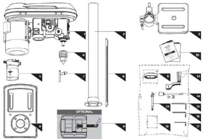
| 1 | Machinen Kopf / Machine HeadGlava stroja / Hlava strojaTête d'usinage /Glava stroja | 10 | Bedienungsanleitung / manualNavodilo za uporabo / Návod na obsluhuMode d'emploi /Uputa za uporabu |
| 2 | Säule / Column tubeStojalo / StípikColonne /Stup | 11 | Verstellring / CollarNastavljiv obroč / Nastavovací krúžokAnneau de réglage /Prsten za namještanje |
| 3 | Bohrtisch / Drilling BenchVrtalna miza / Vřtací stôlTable de perçage /Stol za bušenje | 12 | Kurbel Höhenverstellung / height crankRočica za nastavitev višine / Klůka nastavenia výškyManivelle de réglage en hauteur /Koljenasta ručica za namještanje visine |
| 4 | Bohrfutter / Drill chuckVrtalna glava / SkľúčidloMandrin de perçage /Stezna glava | 13 | Tiefen Anschlag / depth stopOmejevalnik globine / Hĺbkový dorazButée de profondeur /Graničnik dubine |
| 5 | Bohrfutterschutz / Drill chuck guardZaščita vrtalne glave / Protection du mandrin de perçage /Štitnik stezne glave | 14 | Hebel / drill lifting arm (x3)Ročica za dviganje in spuščanje vrtalne glavePáka / drill lifting arm (x3)Levier /Ručica |
| 6 | Grundplatte / BaseplateOsnovna plošča / Plaque de base /Osnovna ploča | 15 | Imbusschlüssel / Allen key 5mmImbus ključ / Imbusový klúčClé Allen /Imbus ključ |
| 7 | Bohrfutterschlüssel / Drill chuck keyKljuč za vrtalno glavo / Clé de mandrin /Ključ za steznu glavu | 16 | Imbusschlüssel / Allen key 4mmImbus ključ / Imbusový klúčClé Allen /Imbus ključ |
| 8 | Zahnstange / RackZobata letev / Crémaillère /Nazubljena letvica | 17 | Imbusschlüssel / Allen key 3mmImbus ključ / Imbusový klúčClé Allen |
| 9 | Maschinenschraubstock (optional)Plier (optional)Štrojni primež (opcija)Étau de la machine (en option)Škripac stroja (opcionalno) | 18 | Schraubenbeutel (inkludiert) /Hardware bag (incl.)4x M8x20; 2x M10x35 (optional)Komplet vijakov (priložen)Vak so skrutkami (súčastou balenia)Poche de boulonnerie (inclue)Vrećica s vijcima (uključena) |
3.3 Technische Daten / Technical data / Tehnični podatki / Technické údaje / Données techniques / Tehnički podaci
| ZI-STB16T | |
| Betriebsspannung / VoltageObratovalna napetost / NapätieTension de fonctionnement /Radni napon | 230 V / 50 Hz |
| Motorleistung / motor powerMoč motorja / Výkon motoraPuissance du moteur /Snaga motora | 630 W (S2 15min) |
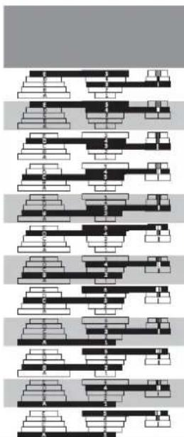
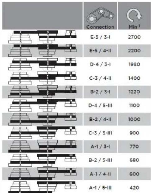
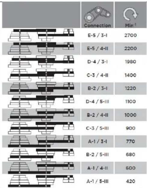
| Spindeldrehzahl / spindle speedŠtevilo vrtljajev svedra / Otáčky vretenaVitesse de broche /Broj okretaja vretena | 420/600/680/770/900/1000/1100/1220/1400/1980/2200/2700 min-1 |
| Spindelhub / Spindle strokeHod vrtalne glave / Zdvih vretenaCourse de la broche /Podizaj vretena | 60 mm |
| Ausladung / distance spindle to columnRazdalja med vrtalno glavo in stojalom / VyloženiePortée /Prevjes | 126mm |
| Schutzklasse / safety classZaščitni razred / Ochranná triedaClasse de protection /Klasa zaštite | I |
| Schutzart / protection categoryVrsta zaščite / OchranaClasse /Vrsta zaštite | IP 20 |
| Schall-Druckpegel / Sound pressure levelNivo zvočnega tlaka / Hladina akustického tlakuNiveau de pression acoustique /Razina zvučnog tlaka LPA | 67 dB(A) K=3dB(A) |
| Schall-Leistungspegel / Sound power levelNivo zvočne moči / Hladina akustického výkonuNiveau de puissance acoustique / Razina zvučne snage LWA | 80 dB(A) K=3dB(A) |
| Bohrfutter / Drill ChuckVrtalna glava / Sklúčidlo min -max øMandrin de perçage / Stezna glava | 3 - 16 mm |
| Gewicht / weightTeža /HmotnosťPoids / Težina | 30 kg |
| Dimension Bohrtisch / drill bench dimensionDimenzije vrtalne mize / Rozmer vřtacieho stolaDimensions de la table de perçage / Dimenzije stola za bušenje | 195 x 195 mm |
| Dimension Grundplatte / baseplateDimenzije osnovne plošče / Rozmer základovej doskyDimensions de la plaque de base / Dimenzije osnovne ploče | 343 x 213 mm |
| Abstand Spindel-Tisch / distance spindle to worktableRazdalja med vrtalno glavo in vrtalno mizo / Vzdialenosť vreteno-stôlDistance du plateau des broches / Razmak vreteno-stol | 410 mm |
| Abstand Spindel-Grundplatte / distance spindle to baseRazdalja med vrtalno glavo in osnovno ploščo / Vzdialenosť vreteno-základová doskaDistance de la plaque de base de broches / Razmak vreteno-osnovna ploča | 525 mm |
| Dimesion Maschine (LxBxH) / machineDimenzije stroja / Rozmer strojaDimensions de la machine / Dimenzije stroja | 475 x 295 x 840 mm |
| Spindelkonus / spindle taperVrtalna konica / Kužel'vretena / Cône de broche /Konus vretena | JT33/B16 |
4 VORWORT (DE)

bar
| Category | Connection (Mln⁻¹) | |---|---| | E-5 / 3-I | 2700 | | E-5 / 4-II | 2200 | | D-4 / 3-I | 1980 | | C-3 / 4-II | 1400 | | B-2 / 3-I | 1220 | | D-4 / 5-III | 1100 | | B-2 / 4-II | 1000 | | C-3 / 5-III | 900 | | A-1 / 3-I | 770 | | B-2 / 5-III | 680 | | A-1 / 4-II | 600 | | A-1 / 5-III | 420 |This manual contains important information and advice for the correct and safe use and maintenance of the drill press ZI-STB16T.
Following the usual commercial name of the device (see cover) is substituted in this manual with the name "machine".
The manual is part of the machine and may not be stored separately. Read it profoundly before first use of the machine and keep it for later reference. When the machine is handed to other persons always put the manual to the machine.
Please follow the security instructions!
Please read the entire manual, to prevent misunderstandings, machine damage or even injuries!

Due to continuous development of our products illustrations, pictures might differ slightly.
If you however find errors in this manual, please inform us.
Technical changes excepted!
Copyright law
© 2018
This manual is protected by copyright law – all rights reserved. Especially the reprinting as well as the translation and depiction of pictures will be prosecuted by law. Court of jurisdiction is the Landesgericht Linz or the competent court for 4707 Schlüsslberg, AUSTRIA.
Customer Support
The machine must only be used for its intended purpose! Any other use is deemed to be a case of misuse. To use the machine properly you must also observe and follow all safety regulations, the assembly instructions, operating and maintenance instructions lay down in this manual.
All people who use and service the machine have to be acquainted with this manual and must be informed about the machine's potential hazards. It is also imperative to observe the accident prevention regulations in force in your area. The same applies for the general rules of occupational health and safety.
The machine is used for:
Drilling in wood, plastic and metal with chuck B16/1.5-16mm.
Work the materials only with suitable drills.
This machine is not intended for use by persons (including children) with reduced physical, sensory or mental capabilities, or lack of experience and knowledge, unless they have been given supervision or instruction concerning use of the machine by a person responsible for their safety. Never allow children or people unfamiliar with these instructions to use the machine. Supervise children. This will ensure that children do not play with the unit.
Any manipulation of the machine or its parts is a misuse, in this case ZIPPER-Maschinen and its sales partners cannot be made liable for ANY direct or indirect damage.

WARNING
- Use only drills allowable for this machine!
- Never use a damaged drill!
- Never use the machine with defective or without mounted guards!
- The removal or modification of the safety components may result in damage to equipment and serious injury!
HIGHEST RISK OF INJURY!
Ambient conditions
The machine may be operated:
humidity
max. 70%
temperature
+5°C to +40°C (+41°F to +104°F)
The machine shall not be operated outdoors or in wet or damp areas.
The machine shall not be operated in areas exposed to increased fire or explosion hazard.
Prohibited use
- The operation of the machine outside the stated technical limits described in this manual is forbidden.
- The operation of the machine without provided protective devices is prohibited.
- The use of the machine not according with the required dimensions is forbidden.
- The use of the machine not being suitable for the use of the machine and not being certified is forbidden.
• Any manipulation of the machine and parts is forbidden. - The use of the machine for any purposes other than described in this user-manual is forbidden.
- The unattended operation on the machine during the working process is forbidden!
- It is not allowed to leave the immediate work area during the work is being performed.
11.2 Safety instructions
Missing or non-readable security stickers have to be replaced immediately!
The locally applicable laws and regulations may specify the minimum age of the operator and limit the use of this machine!
To avoid malfunction, machine defects and injuries, read the following security instructions!

NOTICE
In this machine following protective equipment is in effect:
• Emergency button on the control panel
- Shutdown when opening the belt cover or spindle guard
- Emergency button on the control panel - Shutdown when opening the belt cover or spindle guard
- Keep your work area dry and tidy! An untidy work area may cause accidents. Avoid slippery floor.
• Make sure the work area is lighted sufficiently
• Work only in a well ventilated area - Do not overload the machine
- Provide good stability and keep balance all times
- Avoid abnormal working postures! Make sure you stand squarely and keep balance at all times.
- Keep away from the running drill!
- Always stay focused when working. Reduce distortion sources in your working environment. The operation of the machine when being tired, as well as under the influence of alcohol, drugs or concentration influencing medicaments is forbidden.
- Do not climb onto the machine!
- Attach the machine to the underground.
- Only one person shall operate the machine.
- The machine must be operated only by trained persons (knowledge and understanding of this manual), which have no limitations of motor skills compared with conventional workers.
- Do not allow other people, particularly children, to touch the machine or the cable. Keep them away from your work area.
• Make your workshop childproof.
• Make sure there is nobody present in the dangerous area. The minimum safety distance is 2 m - Wear suitable work clothes! Do not wear loose clothing or jewelry as they might be caught and cause severe accidents!
- Wear a hair net if you have long hair.
- Loose objects can become entangled and cause serious injuries!
- Use personal protective equipment. Always wear eye protection. Protective equipment such as dust mask, non-skid safety shoes, hard hat, or hearing protection used for appropriate conditions will reduce personal injuries. Operation with gloves forbidden
- Never leave the machine running unattended! Before leaving the working area switch the machine off and wait until the machine stops.
• Always disconnect the machine prior to any actions performed at the machine. - Avoid unintentional starting
- Do not use the machine with damaged switch
- The plug of an electrical tool must strictly correspond to the socket. Do not use any adapters together with earthed electric tools
- Each time you work with an electrically operated machine, caution is advised! There is a risk of electric shock, fire, cutting injury;
- Protect the machine from dampness (causing a short circuit)
- Use power tools and machines never in the vicinity of flammable liquids and gases (danger of explosion)
- Check the cable regularly for damage
- When working with the machine outdoors, use extension cables suitable for outdoor use
- Do not use the cable to carry the machine or to fix the work piece
- Protect the cable from heat, oil and sharp edges
- Avoid body contact with earthed components
- Before starting the machine remove any adjusting wrenches and screwdrivers
- Use a clip or clamping jaws to secure the workpiece
- Do not fix the workpiece with your hands
- Rotating parts can cause severe cut injuries
- Keep the drills sharp and clean, so they get stuck less often and are easier to guide
- Keep any machine that is not being used out of reach of children
- Any repairs must only be carried out by the authorized service agent.
11.3 Remaining risk factors

WARNING
It is important to ensure that each machine has remaining risks. In the execution of all work (even the simplest) greatest attention is required. A safe working depends on you!
Even if the machine is used as required it is still impossible to eliminate certain residual risk factors totally. The following hazards may arise in connection with the machine's construction and design:
- Risk of injury to the hands / fingers by the rotating tool during operation.
- Risk of injury due to sharp edges of the workpiece, especially in non-fixed with a suitable tool / device workpiece.
- Risk of injury: hair and loose clothing, etc. can be captured and wound up! Safety regulations must be observed with regard to clothing.
- Risk of injury due to contacting with live electrical components.
- Risk of injury due to dust emissions, treated with harmful agents workpieces
- Risk of injury to the eye by flying debris, even with safety goggles.
- Risk of injury to the hearing by prolonged working without hearing protection.
These risk factors can be minimized through obeying all security and operation instructions, proper machine maintenance, proficient and appropriate operation by persons with technical knowledge and experience.
In spite of all safety is and remains her healthy common sense and their corresponding technical qualification / training for use of the machines most important safety factor!
12 ASSEMBLY
Please check the product contents immediately after receipt for any eventual transport damage or missing parts. Claims from transport damage or missing parts must be placed immediately after initial machine receipt and unpacking before putting the machine into operation. Please understand that later claims cannot be accepted anymore.
12.1 Preparatory activities
12.1.1 Workplace requirements
The workplace has to fulfill the requirements.
The ground has to be even, in level and hard. It must be suitable at least to weight it with double weight per square meter than the machines net weight.
The chosen workplace must have access to a suitable electric supply net hat complies with the machines requirements.
12.1.2 Transport
The machine can be transported in package with a forklift.
The machine is very heavy. The machine shall be lifted from crate with a suitable lifting device only that is certified to be able to carry the machines load.

WARNING
The lifting and transportation of the machine must only be carried out by qualified staff and must be carried out with appropriate equipment.
Note that lifting equipment used (crane, forklift, sling, etc.) must be in perfect condition.
To maneuver the machine in the packaging can also a pallet jack or a forklift be used.
12.1.3 Preparation of the surface
Uncoated metal machine parts have been insulated with a greasy layer to inhibit corrosion.
This layer has to be removed. You can use standard solvents that do not damage the machine surface.

NOTICE
Do not use solvents based on nitrite, aggressive solvents like break cleaners or scrubbing agents!
These damage the machine surface.
12.2 Power supply

ATTENTION
When working with non-grounded machines:
Severe injury or even death may arise though electrocution!
Therefore: The machine must be operated at a grounded power socket
The connection of the machine to the electric power supply and the following checks have to be carried out by a respectively trained electrician only.
- The electronic connection of the machine is designated for operation with a grounded power socket!
- The mains supply must be secured with 16A:
- If the connector plug doesn't fit or if it is defect, only qualified electricians may modify or renew it!
- The grounding wire should be held in green-yellow.
- Check, whether the feeding voltage and the Hz comply to the required values of the machine. A deviation of feeding voltage of ±5% is allowed
- After connecting, check the right running direction (400V)!
- Make sure that a possible extension cord is in good condition and suitable for the transmission of power. An undersized cord reduces the transmission of power and heats up.
- A damaged cable must be replaced immediately

NOTICE
Operation is only allowed with safety switch against stray current (RCD max. stray current of 30mA)


NOTICE
Use only permitted extension cable with cross-section the one in the following table declared.

| Voltage | Extension | Cross-section |
| 220 V-240 V50 Hz | <27 m | 1,5 mm^2 |
| <44 m | 2,5 mm^2 | |
| <70 m | 4,0 mm^2 | |
| <105 m | 6,0 mm^2 |
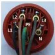
Plug 400V:
5-wire:
with
N-conductor
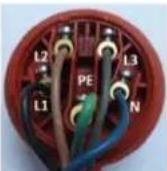
4-wire:
without
N-conductor
12.3 Assembly
| Place the column tube on the baseplate. Bolt the column tube to the baseplate with the four screws M8×20 supplied. Tighten the screws moderately tight with an open end wrench SW 13 (not scope of delivery) so that the threads in the baseplate do not strip. | 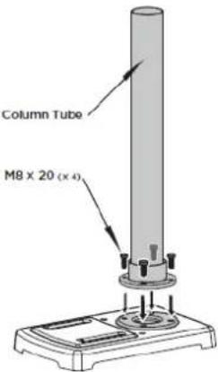 | Place the drilling bench holder over the rack. The teeth of track must mesh with the teeth of gear. (see figure 1).Slide the drilling bench on the column tube.Make sure the bottom bevel of rack insert into the bottom disc of the column tube. (see fig. 2) | 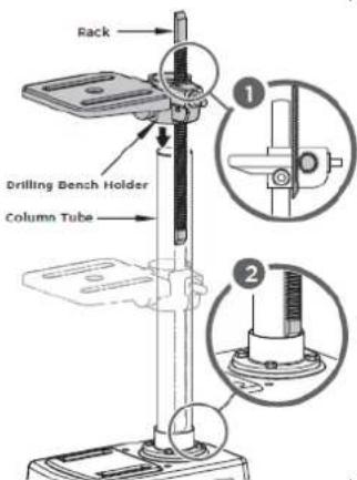 |
| Slide the collar over the column tube with beveled edge facing down until it presses against the top of the rack. (see fig. 3)Tight the set screw, but do not overtighten it. (see fig. 4) | 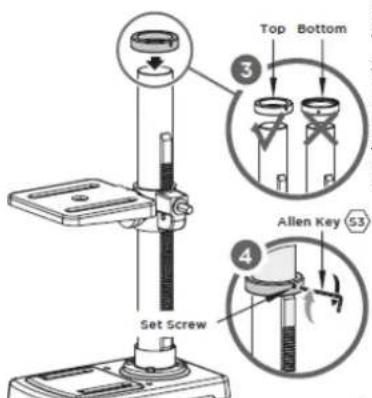 | Slide the height crank over the shaft on the side of drilling bench. (see fig. 5)Secure the height crank to the shaft using allen key 3mm. (see fig. 6) | 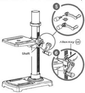 |
| Place the machine head on the column tube and secure the machine head with the two grub screws tot he side with the allen key 4mm. | 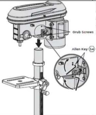 | Put the drill chuck guard on the upper part oft he drill spindle. Secure the drill chuck guard with a screwdriver. | 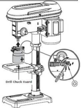 |
| Fold the drill chuck guard upwards.Insert the drill chuck on the taper of the drill spindle.Push the drill chuck onto the drill spindle with a few light tabs. Use a plastic hammer for this purpose. | 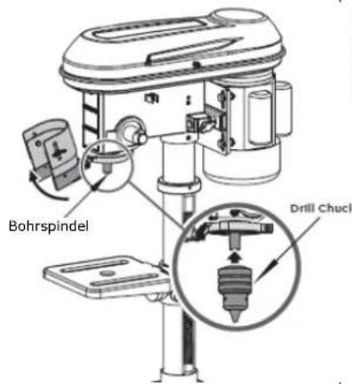 | Bolt the three drill lifting arms into the hand spindle guide and fix them. | 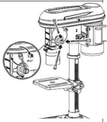 |
| Attach the drill chuck key into the key holder | 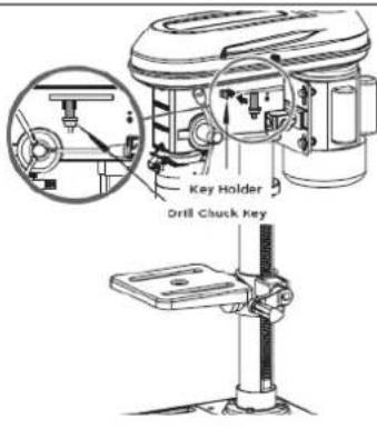 | 1. Remove the washer and nut from the depth stop. (see fig. 1)2. Insert the depth stop through the hole in the fence. (see fig. 2)3. Screw the depth stop with washer and nut that just had been removed from step 1. Centrally align the depth stop into the bore of the fence (see fig. 3)4. The home position of pointer should be 0mm. (see fig. 4) | 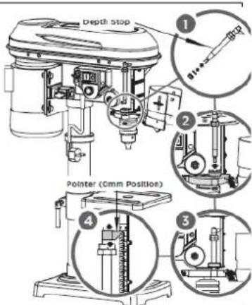 |
| The plier is optional, with bolts, flat washers and nuts mounted on the drilling bench or the baseplate. | 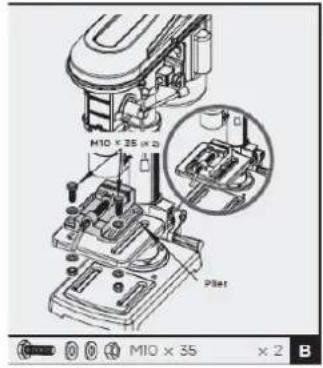 |
13 OPERATION
Device to be operated in a perfect state only. Inspect the device visually every time it is to be used. Check in particular the safety equipment, electrical controls, electric cables and screwed connection for damage and if tightened properly. Replace any damaged parts before operating the device.
13.1 Operation instructions

WARNING
Perform all machine settings with the machine being disconnected from the power supply!

ATTENTION

- Do not attempt to drill material with the surface other than flat unless a suitable support is available!
- Never switch the machine on while pressing the drill bit against the material!

NOTICE
- Before switching the machine on, make sure that the table-clamping lever is firmly tightened
• Make sure that the bit is firmly clamped in the chuck - Due to the height of its own weight is the fixation of the drill press to the ground requirement for less-vibration work.
- Use a clip or clamping jaws to secure the piece to be drilled on the table
- Set the drill to speed answering a specific job
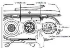
- Check the V-belts and tighten if necessary
- Overtightening the belts can cause the motor to bind and not start. It can also damage motor bearings!
• In advanced wear of, replace V-belt
• V-belts and pulleys may not come into contact with grease, oil or other lubricants - Loosen the V-belt for a long break
• After drilling guide the spindle back to the top position by hand.
13.2 Operation
Switching ON:
- Belt cover and spindle guard must be closed!
- Release the EMERGENCY-switch (a) by turning clockwise.
- Push the ON-button (b).
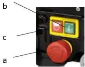
Switching OFF:
- Push OFF-button (c).
• In emergency the machine can be stopped by pushing the EMERGENCY-switch (a).
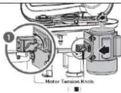
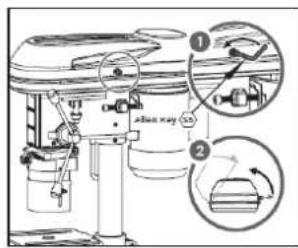
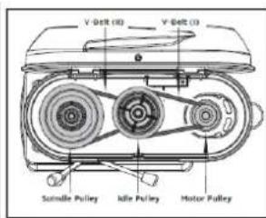
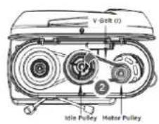
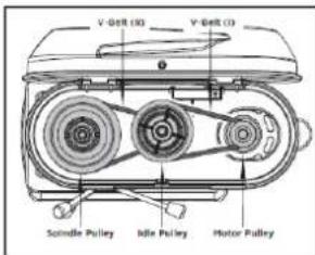
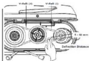
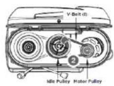
- Release the locking screw on the gear cover with the allen key 5 mm.
- Pull the locking screw and open the gear cover.
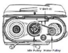
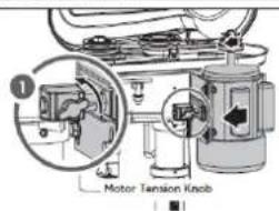
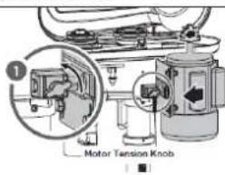
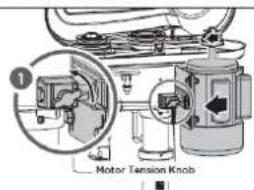
- Loosen the motor tension knob on each side of the headstock.
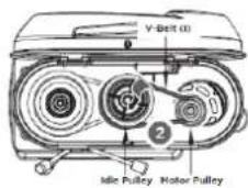
- Slide the motor forward a little to release the load on the V-belts. See below illustration 2.
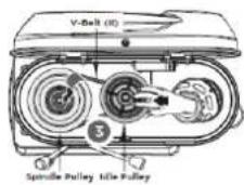
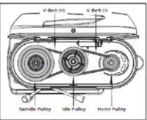
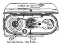
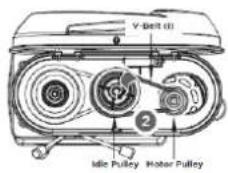
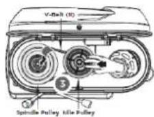
- Remove the V-belt between idle pulley and motor pulley first, then slide idle pulley towards the spindle pulley to release the load on the V-belt between idle pulley and spindle pulley. Remove the second V-belt. See 2 & 3.
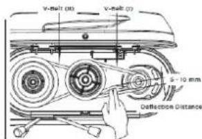
- Place the two V-belts on the desired assembly to reach the specified speed. (see table)
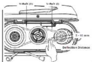
- Slide the motor back to tension the V-belts again. The V-belts are correctly tensioned when it gives way slightly when pressed. Deflection distance of belt is 5-10mm.
- Lock this position with the two motor tension knobs.
- Close the gear cover. Fasten the locking screw on the gear cover with the allen key 5 mm.

The Ground Truth image displays a single, solid horizontal line. According to Rule 2 (UNDERSCORE & LINE RULES), this is a stylistic or background line, not a placeholder underscore. Therefore, the OCR result must ignore it and output nothing or only meaningful text. The provided OCR content is "\_\_\_\_", which consists of four underscores. This is an incorrect interpretation of the line as a placeholder, violating the rule that stylistic lines must be ignored. The OCR has hallucinated placeholder underscores where none exist in the GT. Hence, the OCR result is inconsistent with the Ground Truth.
Soft material => high rotation speed Hard material => low rotation speed
Adjusting the Drilling Bench (Height, tilt angle)
- Release the locking handle
- Rotate the height crank clockwise or counter clockwise to desired height.
- Pivot the drilling bench to the desired position
- Fasten the drilling bench again with the locking handle.
- You can also adjust the tilt angle of the drilling bench. To do this, release the retaining screw under the drilling bench with an open end wrench SW19 (not scope of delivery). Tilt the drilling bench as described to the right or left up to a max. of 45° and secure the drilling bench again with the retaining screw.

Setting drilling depth:
- Adjust the depth stop to desired depth.
• The depth is shown on the scale.
Changing the drill:
- Fold the drill chuck guard up.
- Release the retaining jaws of the drill chuck with the drill chuck key.
- Remove the bit.
- Insert a new bit.
- Tighten the retaining jaws of the drill chuck with the drill chuck key.
- Check that the bit is centred.
- Fold the drill chuck guard down again.
- Attach the drill chuck key back to the key holder. Using a quick chuck:
- Open the keyless chuck by turning in against rotation direction A and holding ring B until the drill can be inserted.
- Insert the drill.
- Firmly tighten the collar of the keyless chuck by hand in rotation direction A and holding ring B.
• This automatically locks the drill chuck.
14 MAINTENANCE

ATTENTION
Perform all maintenance machine settings with the machine being disconnected from the power supply!
Serious injury due to unintentional or automatic activation of the machine!

The machine does not require extensive maintenance. If malfunctions and defects occur, let it be serviced by trained persons only.
Before first operation as well as later on every 100 operation hours you should lubricate all connecting parts (if required, remove beforehand with a brush all swarfs and dust).
Check regularly the condition of the security stickers. Replace them if required.
Check regularly the condition of the machine.
Store the machine in a closed, dry location.
NOTICE
Clean your machine regularly after every usage – it prolongs the machines lifespan and is a prerequisite for a safe working environment.
Repair jobs shall be performed by respectively trained professionals only!
14.1 Maintenance plan
After each workshift:
- Apply a thin layer of oil on the column and the table
- Remove drill cuttings and metal chips
After 50 hours of operation
- Apply some fat on the angle drift
14.2 Cleaning
After each workshift the machine has to be cleaned. Remove chips etc. with a suitable tool. Do not remove them by hand (cutting injury!). Remove dust as well.

NOTICE
The usage of certain solutions containing ingredients damaging metal surfaces as well as the use of scrubbing agents will damage the machine surface!
Clean the machine surface with a wet cloth soaked in a mild detergent
14.3 Disposal
Do not dispose the machine in residual waste. Contact your local authorities for information regarding the available disposal options. When you buy at your local dealer for a replacement unit, the latter is obliged to exchange your old.

15 TROUBLE SHOOTING
BEFORE YOU START WORKING FOR THE ELIMINATION OF DEFECTS, DISCONNECT THE MACHINE FROM THE POWER SUPPLY.
| Trouble | Possible cause | Solution |
| Motor does not run | Incorrect power supply | Let it be checked by a trained person |
| Switch defect | Change | |
| Motor defect | Change | |
| Safety switch activated | Check the belt cover or spindle guard (open?). | |
| Loud noise when running | Incorrect belt tension | Adjust belt tension (1cm rule) |
| Drill runs erratically | Drill chuck not assembled correctly to arbour or one of them is dirty | Check and adjust. |
| Drill chuck jaws worn or damaged | Change drill chucj | |
| Spindle or boring is worn | Check and replace if necessary | |
| Drill is hot and smokes | Too fast speed for material being drilled | Reduce speed use lubricants |
| Motor runs but no rotation or weak drilling power | Belt tension too lowPulley belt dirty, slippery | TightenClean |
MANY POTENTIAL SOURCES OF ERROR CAN BE CLEARED BY THE EXPERTLY CONNECTION TO THE ELECTRICITY GRID.

NOTICE
Should you in necessary repairs not able to properly to perform or you have not the prescribed training for it always attract a workshop to fix the problem.
16 UVOD (SL)
Spoštovani kupec!
flowchart
graph TD
    A["Top Step"] --> B["Step 1"]
    B --> C["Step 2"]
    C --> D{Decision}
    D -->|Yes| E["Step 3"]
    D -->|No| F["Step 4"]
    E --> G["Step 5"]
    F --> H["Step 6"]
    G --> I["Step 7"]
    H --> J["Step 8"]
    I --> K["End"]
    J --> K
    style A fill:#f9f,stroke:#333
    style K fill:#bbf,stroke:#333


E-5 / 3-1
2700
E-5/4-II
2200
D-4 / 3-1
1980
C-3/4-11
1400
B-2/3-1
1220
B-2/4-11
1000
C-3 / 5-III
900
A-1/3-1
770
B-2 / 5-11
680
A-1/4-II
600
A-1 / 5-III
420
bar
| Category | Connection (Min⁻¹) | |---|---| | E-5 / 3-I | 2700 | | E-5 / 4-II | 2200 | | D-4 / 3-I | 1980 | | C-3 / 4-II | 1400 | | B-2 / 3-I | 1220 | | D-4 / 5-III | 1100 | | B-2 / 4-II | 1000 | | C-3 / 5-III | 900 | | A-1 / 3-I | 770 | | B-2 / 5-III | 680 | | A-1 / 4-II | 600 | | A-1 / 5-III | 420 |Cher client, chère cliente,
natural_image
Close-up of a red electrical terminal block with labeled wires (L1, L2, PE, N) and no readable text or symbols beyond labels.36.3 Sastavljanje
| Stup postavite na osnovnu ploču i fiksirajte ga s pomoću 4 vijaka M8x20. | 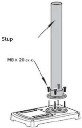 | Stavite držač stola za bušenje iznad nazubljene letvice. Pazite da se zupci nazubljene letvice poklapaju s onima na držaču stola za bušenje (vidi 1). Nazubljenu letvicu i držač stola za bušenje sada montirajte na stup. Pritom pazite da je nazubljena letvica pričvršćena u donjem prstenu. (vidi 2) | NazletvDržabušeni SI 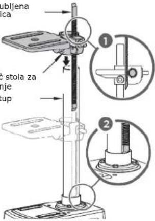 |
| Prsten navucite preko stupa tako da skošeni rub bude okrenut prema dolje sve dok ne dođe do gornje strane nazubljene letvice (vidi 3)Fiksirajte ga navojnim zatikom (vidi 4) | 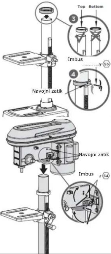 | Koljenastu ručicu gurnite preko vratila (vidi 5) i fiksirajte ju (vidi 6) | 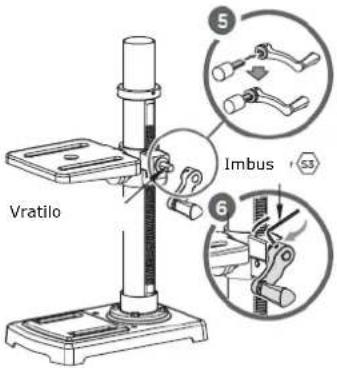 |
| Glavu stroja pričvrstite na stup 2 navojnim zaticima. | Štitnik vretena stavite na gornji kraj vretena i pričvrstite ga pomoću odvijača. | 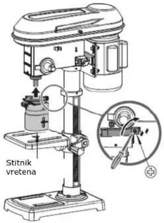 | |
| Štitnik vretenazakrenite prema gore i steznu glavu stavitena konus vretena.Zatim fiksirajte steznu glavu opreznim udarom gumenim čekićem. | 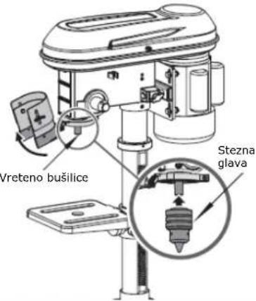 | Vijcima pričvrstite 3poluge i pritegnite ih. | 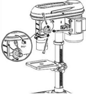 |
| Ključ za steznu glavupričvrstite u držaču. |  | Podlošku i maticu skinite s graničnikadubine.Umetnite graničnikdubineGraničnik dubinepričvrstite maticom ipodloškom iz 1.korakaNamjestite položaj 0mm na skali. | 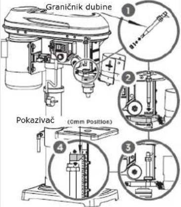 |
| Opcionalni škripacmože se na stol zabušenje pričvrstitivijcima, podloškama imaticama. | 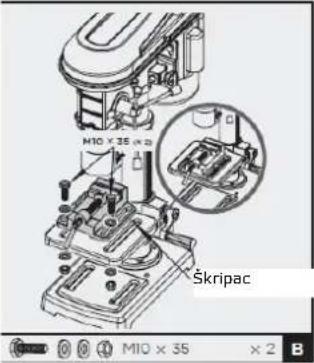 |
37 RAD
bar
| Category | Connection (Min⁻¹) | |---|---| | E-5 / 3-I | 2700 | | E-5 / 4-II | 2200 | | D-4 / 3-I | 1980 | | C-3 / 4-II | 1400 | | B-2 / 3-I | 1220 | | D-4 / 5-III | 1100 | | B-2 / 4-II | 1000 | | C-3 / 5-III | 900 | | A-1 / 3-I | 770 | | B-2 / 5-III | 680 | | A-1 / 4-II | 600 | | A-1 / 5-III | 420 |(EN) With original ZIPPER spare parts you use parts that are attuned to each other shorten the installation time and elongate your machines lifespan.
IMPORTANT
The installation of other than original spare parts voids the warranty!
So you always have to use original spare parts
When you place a spare parts order please use the service formular you can find in the last chapter of this manual. Always take a note of the machine type, spare parts number and partname. We recommend to copy the spare parts diagram and mark the spare part you need.
You find the order address in the preface of this operation manual.
ZI-STB16T
| Pos | Name | Qty | Pos | Name | Qty | Pos | Name | Qty |
| 1 | Base | 1 | 32 | Thin Nut M10 | 6 | 63 | Big Washer 5 | 4 |
| 2 | Column Base | 1 | 33 | Spring Shield | 1 | 64 | Screw M5*10 | 3 |
| 3 | Bolt 8.8 M8*20 | 4 | 34 | Elastic Pin 6*16 | 2 | 65 | Screw M5*16 | 1 |
| 4 | Column | 1 | 35 | Motor Mounting Rod | 2 | 66 | Handle Lever | 3 |
| 5 | Bolt 8.8 12*25 | 1 | 36 | Rivet 4*8 | 4 | 67 | Spacer | 4 |
| 6 | Drilling Bench | 1 | 37 | Motor Mounting Bracket | 1 | 68 | Spring Washer 4 | 2 |
| 7 | Bevel Gear Pin | 1 | 38 | Motor | 1 | 69 | Lock Washer 4 | 2 |
| 8 | Bracket | 1 | 39 | Screw M8*8 | 1 | 70 | Main Case | 1 |
| 9 | Lock Handle | 1 | 40 | V-Bolt | 2 | 71 | Gear Shaft | 1 |
| 10 | Worm | 1 | 41 | Motor Pulley | 1 | 72 | Front Panel | 1 |
| 11 | Bevel Gear | 1 | 42 | Screw ST2.9*6.5 | 2 | 73 | Drill Chuck Key | 1 |
| 12 | Nut M8 | 1 | 43 | Microswitch Box Cover | 1 | 74 | Screw M4*12 | 1 |
| 13 | Thin Nut M8 | 1 | 44 | Microswitch | 1 | 75 | Key Clamp | 1 |
| 14 | Height Crank Handle | 1 | 45 | Microswitch Box | 1 | 76 | Cushion | 1 |
| 15 | Screw M8*50 | 1 | 46 | Screw ST3.5*9.5 | 2 | 77 | Circlip 11 | 1 |
| 16 | Height Crank | 1 | 47 | Clamp | 1 | 78 | Anti-Rotation Screw | 1 |
| 17 | Screw M6*10 | 48 | Upper Belt Cover | 1 | 79 | Coil Spring | 1 | |
| 18 | Cable & Plug | 1 | 49 | Circlip 5 | 1 | 80 | Rack | 1 |
| 19 | Cable Sheath | 1 | 50 | Washer 6 | 1 | 81 | Sleeve | 1 |
| 20 | Switch Panel | 1 | 51 | Screw M6*16 | 1 | 82 | Bearing 6201-2Z | 2 |
| 21 | Screw M4*8 | 6 | 52 | Compression Spring | 1 | 83 | Spindle | 1 |
| 22 | Cable Clamp | 1 | 53 | Left-hand Threaded Nut | 1 | 84 | Drill Chuck | 1 |
| 23 | Screw ST3.5*9.5 | 2 | 54 | Spindle Pulloy | 1 | 85 | Pointer (Rod) | 1 |
| 24 | Collar | 1 | 55 | Idle Gear | 1 | 86 | Locating Rod | 1 |
| 25 | Switch | 1 | 56 | Spline Housing | 1 | 87 | Nut M6 | 1 |
| 26 | Cable Gland | 1 | 57 | Idle Gear Axle | 1 | 88 | Drill Chuck Guard | 1 |
| 27 | Lock Nut M8 | 4 | 58 | Bearing 6203-2Z | 2 | "1 | Nut M10 | 2 |
| 28 | Spring Washer 10 | 2 | 59 | Bearing Spacer | 1 | "2 | Washer 10 | 4 |
| 29 | Washer B | 8 | 60 | Circlip 17 | 1 | "3 | Machine Vise 2.5" | 1 |
| 30 | Bolt M8*25 | 4 | 61 | Handle Knob | 3 | "4 | Bolt 8.8 M10*35 | 2 |
| 31 | Lock Knob | 2 | 62 | Bottom Belt Cover | 1 |
41 EU-KONFORMITÄTSERKLÄRUNG / CE-DECLARATION OF CONFORMITY / EU-IZJAVA O SKLADNOSTI / PSH / DECLARATION DE CONFORMITE UE /EU POTVRDA O SUKLADNOSTI

Inverkehrbringer / Distributor
(EN) Hereby we declare that the above mentioned machines meet the essential safety and health requirements of the above stated EC directives. Any manipulation or change of the machine not being explicitly authorized by us in advance renders this document null and void.
Company ZIPPER Maschinen GmbH grants for mechanical and electrical components a warranty period of 2 years for amateur use; and warranty period of 1 year for professional use, starting with the purchase of the final consumer. In case of defects during this period, which are not excluded by paragraph 3, ZIPPER will repair or replace the machine at its own discretion.
2.) Report:
In order to check the legitimacy of warranty claims, the final consumer must contact his dealer. The dealer has to report in written form the occurred defect to ZIPPER. If the warranty claim is legitimate, ZIPPER will pick up the defective machine from the dealer. Returned shippings by dealers which have not been coordinated with ZIPPER, will not be accepted and refused.
3.) Regulations:
a) Warranty claims will only be accepted, when a copy of the original invoice or cash voucher from the trading partner of ZIPPER is enclosed to the machine. The warranty claim expires if the accessories belonging to the machine are missing.
b) The warranty does not include free checking, maintenance, inspection or service works on the machine. Defects due to incorrect usage of the final consumer or his dealer will not be accepted as warranty claims either. Some examples: usage of wrong fuel, frost damages in water tanks, leaving fuel in the tank during the winter, etc.
c) Defects on wear parts are excluded, e.g. carbon brushes, collection bags, knives, cylinders, cutting blades, clutches, sealings, wheels, saw blades, splitting crosses, riving knives, riving knife extensions, hydraulic oils, oil/air/fuel filters, chains, spark plugs, sliding blocks, etc.
d) Also excluded are damages on the machine caused by incorrect or inappropriate usage, if it was used for a purpose which the machine is not supposed to, ignoring the user manual, force majeure, repairs or technical manipulations by not authorized workshops or by the customer himself, usage of non-original ZIPPER spare parts or accessories.
e) After inspection by our qualified personnel, resulted costs (like freight charges) and expenses for not legitimated warranty claims will be charged to the final customer or dealer.
f) In case of defective machines outside the warranty period, we will only repair after advance payment or dealer's invoice according to the cost estimate (incl. freight costs) of ZIPPER.
g) Warranty claims can only be granted for customers of an authorized ZIPPER dealer who directly purchased the machine from ZIPPER. These claims are not transferable in case of multiple sales of the machine.
4.) Claims for compensation and other liabilities:
The liability of company ZIPPER is limited to the value of goods in all cases. Claims for compensation because of poor performance, lacks, damages or loss of earnings due to defects during the warranty period will not be accepted. ZIPPER insists on its right to subsequent improvement of the machine.
44 GARANCIJA (SL)
1.) Garancija:
Product experience form
We observe the quality of our delivered products in the frame of a Quality Management policy.
Your opinion is essential for further product development and product choice. Please let us know about your:
- Impressions and suggestions for improvement.
- experiences that may be useful for other users and for product design
- Experiences with malfunctions that occur in specific operation modes
We would like to ask you to note down your experiences and observations and send them to us via FAX, E-Mail or by post:
Erworben von / purchased from:
E-Mail/ e-mail:
Please describe amongst others in the problem: What has cause the problem/defect, what was the last activity before you noticed the problem/defect? For electrical problems: Have you had checked you electric supply and the machine already by a certified electrician?
3. Bitte beachten
/ Additional information
INCOMPLETELY FILLED SERVICE FORMS CANNOT BE PROCESSED! FOR GUARANTEE CLAIMS PLEASE ADD A COPY OF YOUR ORIGINAL SALES / DELIVERY RECEIPT OTHERWISE IT CANNOT BE ACCEPTED. FOR SPARE PART ORDERS PLEASE ADD TO THIS SERVICE FORM A COPY OF THE RESPECTIVE EXPLODED DRAWING WITH THE REQUIRED SPARE PARTS BEING MARKED CLEARLY AND UNMISTAKABLE. THIS HELPS US TO IDENTIFY THE REQUIRED SPARE PARTS FASTLY AND ACCEL- ERATES THE HANDLING OF YOUR INQUIRY.