ZI-ABH1050 - Drill Zipper - Free user manual and instructions
Find the device manual for free ZI-ABH1050 Zipper in PDF.

| Type de produit | Demolition hammer |
| Modèle | ZI-ABH1050 |
| Marque | Zipper |
| Tension nominale | 230 V, 50 Hz |
| Puissance du moteur | 1050 W |
| Nombre de frappes par minute | 2000 min⁻¹ |
| Énergie de frappe individuelle | 38 Joules |
| Poids | 11 kg |
| Dimensions de l'outil | ∅ 21 x 300 mm |
| Niveau de pression acoustique (LPA) | 98,5 dB(A) |
| Niveau de puissance acoustique (LWA) | 105 dB(A) |
| Valeur d'émission vibratoire | 12,711 m/s² |
| Type de mandrin | Hexagonal ∅ 21 mm |
| Utilisation prévue | Burinage dans le béton, la brique et la pierre |
| Contenu de la livraison | Marteau burineur, burin plat, burin pointu, charbons, huile, clé Allen, clé, graisse |
| Classe de protection | II |
| Entretien | Nettoyage après chaque utilisation, changement des charbons toutes les 100 heures |
| Température de fonctionnement | +5 °C à +40 °C |
| Humidité maximale | 70 % |
| Garantie | 2 ans (usage amateur), 1 an (usage professionnel) |
Frequently Asked Questions - ZI-ABH1050 Zipper
User questions about ZI-ABH1050 Zipper
0 question about this device. Answer the ones you know or ask your own.
Ask a new question about this device
Download the instructions for your Drill in PDF format for free! Find your manual ZI-ABH1050 - Zipper and take your electronic device back in hand. On this page are published all the documents necessary for the use of your device. ZI-ABH1050 by Zipper.
USER MANUAL ZI-ABH1050 Zipper
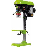
natural_image
Two green ZIPPER 1500 power tools, one with blade and handle, the other with handle and blade (no text or symbols visible on the devices themselves)
ZI-ABH1050 / ZI-ABH1500
CE
EAN :912003923088 7
912003923058 0
EN Read the operation manual carefully before first use.
1 INHALT / INDEX
2 VORWORT 5
11.2 Technical Details 25
12 SAFETY 26
12.1 Intended Use 26
12.2 Security instructions 27
12.3 Remaining risk factors 29
13 ASSEMBLY 30
13.1 Delivery content.... 30
13.1.1 ZI-ABH1050 30
13.1.2 ZI-ABH1500 30
14 OPERATION 31
14.1 Operation instructions 31
14.2 Operation ZI-ABH1050....32
14.2.1 Insert chisel 32
14.2.2 Switch on 32
14.2.3 Switch off 32
14.3 Operation ZI-ABH1500....34
14.3.1 Insert chisel 34
14.3.2 Switch on 34
14.3.3 Switch off 35
14.3.4 ÖL einfüllen 35
15 MAINTENANCE 36
15.1 Maintenance plan....36
15.2 Changing the carbon brushes....37
15.3 Cleaning 37
15.4 Disposal 37
16 TROUBLE SHOOTING 38
17 ERSATZTEILE / SPARE PARTS 39
ATTENTION! Ignoring the safety signs and warnings applied on the machine as well as ignoring the security and operating instructions can cause serious injuries and even lead to death.

DE
READ THE MANUAL! Read the user and maintenance manual carefully and get familiar with the controls n order to use the machine correctly and to avoid injuries and machine defects.

EC-CONFORM: This product complies with EC-directives

DE
Allgemeiner Hinweis
EN
General note


DE
Protective clothing!

DE
EN Protection class II!

EN Operation with jewelry forbidden!

EN Operation with tie forbidden!

EN Operation with long hair forbidden!


EN Stop and pull out the power plug before any break and engine maintenance!

EN Warning of rotating parts!

EN Protect from moisture!
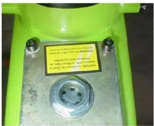
EN ATTENTION! For transport oil has been drained. Fill up with lubrication oil before first operation! Failure to do so will result in permanent engine damage and void guarantee.
4 TECHNIK
4.1 Komponenten
4.1.1 ZI-ABH1050
4.1.2 ZI-ABH1500
6.1.2 ZI-ABH1500
natural_image
Close-up of a hand holding a green spray gun and black textured object against a concrete wall (no text or symbols visible)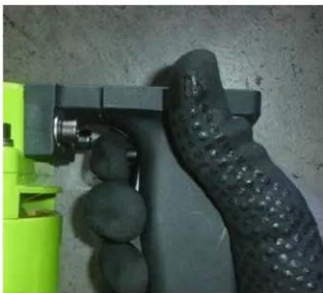
natural_image
Close-up of a hand holding a green and black plastic device against a textured wall (no visible text or symbols)7.2.3 Ausschalten
natural_image
Close-up of a metallic mechanical component with bolts and a hexagonal nut, held by gloved hands (no visible text or symbols)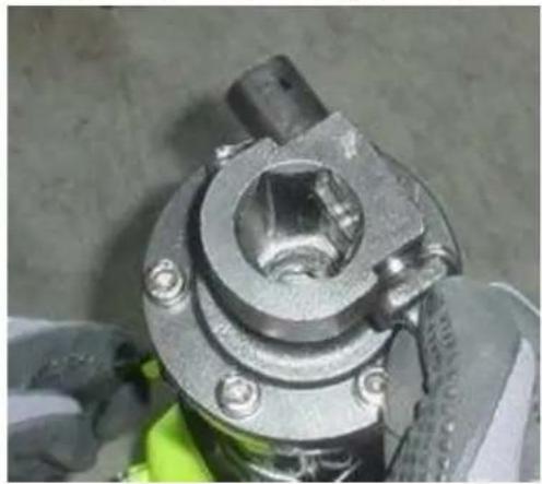
natural_image
Close-up of a mechanical component with bolts and a central hub, partially covered by gloved hands (no visible text or symbols)natural_image
Close-up of a mechanical component with a metallic shaft and flange (no visible text or symbols)7.3.2 Einschalten
natural_image
Close-up of a hand holding a green spray gun and black textured object against a concrete wall (no text or symbols visible)
natural_image
Close-up of a hand holding a green and black handheld device against a textured wall (no visible text or symbols)7.3.3 Ausschalten
natural_image
Close-up of a mechanical device with a metallic bolt and green base, showing a hand holding a transparent tube (no visible text or symbols)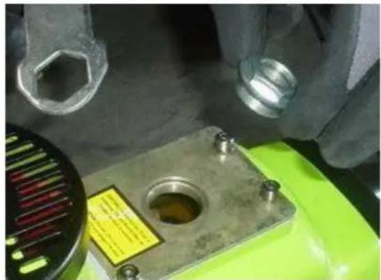
natural_image
Close-up of a mechanical component with a green base and metallic housing, no visible text or symbolsnatural_image
Close-up of a green and black industrial machine with a yellow screwdriver inserted, no visible text or symbols.
natural_image
Close-up of a green industrial machine component with a metal clamp, no visible text or symbols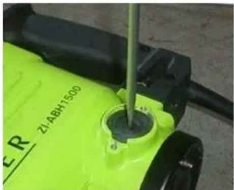
natural_image
Close-up of a green electric water heater with a screwdriver inserted, showing internal components and no visible text or symbols.natural_image
Symbol of a trash bin with crossed lines indicating no waste, and a solid black rectangle below (no text or labels)9 FEHLERBEHEBUNG
This manual contains important information and advice for the correct and safe use and maintenance of the ZI-ABH1050 and ZI-ABH1500.
Following the usual commercial name of the device (see cover) is substituted in this manual with the name "machine".
The manual is part of the machine and may not be stored separately. Read it profoundly before first use of the machine and keep it for later reference. When the machine is handed to other persons always put the manual to the machine.

Please follow the security instructions!
Please read the entire manual, to prevent misunderstandings, machine damage or even injuries!
Due to continuous development of our products illustrations, pictures might differ slightly. If you however find errors in this manual, please inform us.
Technical changes excepted!
Copyright law
© 2013
This manual is protected by copyright law – all rights reserved. Especially the reprinting as well as the translation and depiction of pictures will be prosecuted by law. Court of jurisdiction is the Landesgericht Linz or the competent court for 4707 Schlüsslberg, AUSTRIA.
Customer Support
11.2 Technical Details
| ZI-ABH1050 | ZI-ABH1500 | |
| Rated voltage / frequency | 230V, 50 Hz | 230V, 50 Hz |
| Motor power | 1050 W | 1550 W |
| Hits / minute | 2000 | 1400 |
| Weight | 11 kg | 18 kg |
| Single hit power | 38 Joule | 45 Joule |
| Sound-pressure level L_PA (K=3dB(A)) | 98,5dB(A) | 83 dB(A) |
| Sound-power level L_WA (K=3dB(A)) | 105 dB(A) | 105 dB(A) |
| Guaranteed L_WA | 105 dB(A) | 105dB(A) |
| Vibrations emission (K=1,5 m/s ^2 ) | 12,711 m/s ^2 | 18,981 m/s ^2 |
| Tool dimensions | ∅ 21x300mm | 30x400mm (hexagonal) |
The declared vibration total value has been measured in accordance with a standard test method and may be used for comparing one tool with another.
The declared vibration total value may also be used in a preliminary assessment of exposure.

W ARNI NG
The vibration emission during actual use of the power tool can differ from the declared total value depending on the ways in which the tool is use!
12 SAFETY
12.1 Intended Use
The machine must only be used for its intended purpose! Any other use is deemed to be a case of misuse. The machine is only used for:
Chiseling in concrete, brick and stone.
For installations of pipelines, power lines and demolition work.
To use the machine properly you must also observe and follow all safety regulations, the assembly instructions, operating and maintenance instructions lay down in this manual.
All people who use and service the machine have to be acquainted with this manual and must be informed about the machine's potential hazards.
It is also imperative to observe the accident prevention regulations in force in your area.
The same applies for the general rules of occupational health and safety.
Any manipulation of the machine or its parts is a misuse, in this case HOLZMANN-Machines and its sales partners cannot be made liable for ANY direct or indirect damage.
Even when the machine is used as prescribed it is still impossible to eliminate certain residual risk factors.

W ARNI NG
- Use only chisels allowable for this machine!
- Never use a damaged chisel!
- Use the machine never with defective or without mounted guard HIGHEST RISK OF INJURY!
Ambient conditions
The machine may be operated:
humidity
max. 70%
temperature
+5^ to +40^ (+41^ to +104^)
The machine shall not be operated in areas exposed to increased fire or explosion hazard.
Prohibited use
- The operation of the machine outside the stated technical limits described in this manual is forbidden.
- The use of the machine not according with the required dimensions is forbidden.
- The use of the machine not being suitable for the use of the machine and not being certified is forbidden.
- Any manipulation of the machine and parts is forbidden.
• The use of the machine for any purposes other than described in 12.1 is forbidden. - The unattended operation on the machine during the working process is forbidden!
- It is not allowed to leave the immediate work area during the work is being performed.
12.2 Security instructions
Missing or non-readable security stickers have to be replaced immediately!
To avoid malfunction, machine defects and injuries, read the following security instructions!
The locally applicable laws and regulations may specify the minimum age of the operator and limit the use of this machine!

- Keep your work area dry and tidy! An untidy work area may cause accidents. Avoid slippery floor.
- Make sure the work area is lighted sufficiently
- Do not overload the machine
- Provide good stability and keep balance all times
- Avoid abnormal working postures! Make sure you stand squarely and keep balance at all times.
- Keep away from the running tool!
- Always stay focused when working. Reduce distortion sources in your working environment. The operation of the machine when being tired, as well as under the influence of alcohol, drugs or concentration influencing medicaments is forbidden.

- Respectively trained people only and only one person shall operate the machine.
- Do not allow other people, particularly children, to touch the machine or the cable. Keep them away from your work area.
• Make your workshop childproof. - Make sure there is nobody present in the dangerous area. The minimum safety distance is 2m


- Wear suitable work clothes! Do not wear loose clothing or jewellery as they might get caught in moving parts and cause severe accidents! Wear a hair net if you have long hair.

- Use personal safety equipment: safety gloves, dust musk, ear protectors and safety goggles when working with the machine.

- Never leave the machine running unattended! Before leaving the working area switch the machine off and wait until the machine stops.
- Always disconnect the machine prior to any actions performed at the machine.
- Avoid unintentional starting
- Do not use the machine with damaged switch

- The plug of an electrical tool must strictly correspond to the socket. Do not use any adapters together with earthed electric tools
• Each time you work with an electrically operated machine, caution is advised! There is a risk of electric shock, fire, cutting injury; - Protect the machine from dampness (causing a short circuit)
- Use power tools and machines never in the vicinity of flammable liquids and gases (danger of explosion)
- Check the cable regularly for damage
- When working with the machine outdoors, use extension cables suitable for outdoor use
- Do not use the cable to carry the machine or to fix the work piece
- Protect the cable from heat, oil and sharp edges
- Avoid body contact with earthed

- Before starting the machine remove any adjusting wrenches and screwdrivers
- Parts can cause severe cut injuries
- Keep the chisels sharp and clean, so they get stuck less often and are easier to guide
- Keep any machine that is not being used out of reach of children

NO TI CE
Emergency procedure
A first aid kit in accordance with DIN 13164 should always be read available for a possible accident. Initiate the violation in accordance with the necessary first aid measures. When requesting support, provide the following details:
| 1. Place of accident | 2. Type of accident |
| 3. Number of injured people | 4. Injury type(s) |
12.3 Remaining risk factors

W ARNI NG
It is important to ensure that each machine has remaining risks. In the execution of all work (even the simplest) greatest attention is required. A safe working depends on you!
Even if the machine is used as required it is still impossible to eliminate certain residual risk factors totally. The following hazards may arise in connection with the machine's construction and design:
Despite of correct and proper use and maintenance there remain some residual risk factors:
- Hazard of injury or machine damage due to undetected machine defect
To minimize this risk, check the machine prior to every operation for loose screws and connections. Check the motor noise, the spindle, the drill chuck, etc. for eventual damage. Damaged parts have to be replaced immediately, no operation of the machine in the meantime!
- Hazard of electric shock
Undetected malfunctions in the power supply and/or the connected wood working machine might result in electric shock when touching the machine. Ensure proper electric installation, and let it check periodically by a trained electrician.
• Danger due to unintended machine start-up
Eliminate this risk by disconnecting the machine before you perform any checks or activities on the machine.
- Hazard of inhaling toxic dust
Especially wood dust arising from chemically treated wood and/or lacquer/paint are harmful when inhaled. Therefore wear a suitable breathing mask if required.
These risk factors can be minimized through obeying all security and operation instructions, proper machine maintenance, proficient and appropriate operation by persons with technical knowledge and experience.

WARNING
This machine produces an electromagnetic field during operation. The field may under some circumstances interfere with active or passive medical implants. To reduce the risk of serious or fatal injury, we recommend persons with medical implants to consult their physician and the medical implant manufacturer before operating this machine!
13 ASSEMBLY
13.1 Delivery content
Please check the product contents (see capture 11.1) immediately after receipt for any eventual transport damage or missing parts. Claims from transport damage or missing parts must be placed immediately after initial machine receipt and unpacking before putting the machine into operation. Please understand that later claims cannot be accepted anymore.
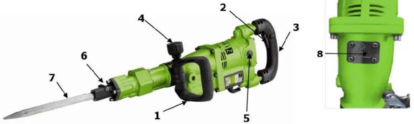
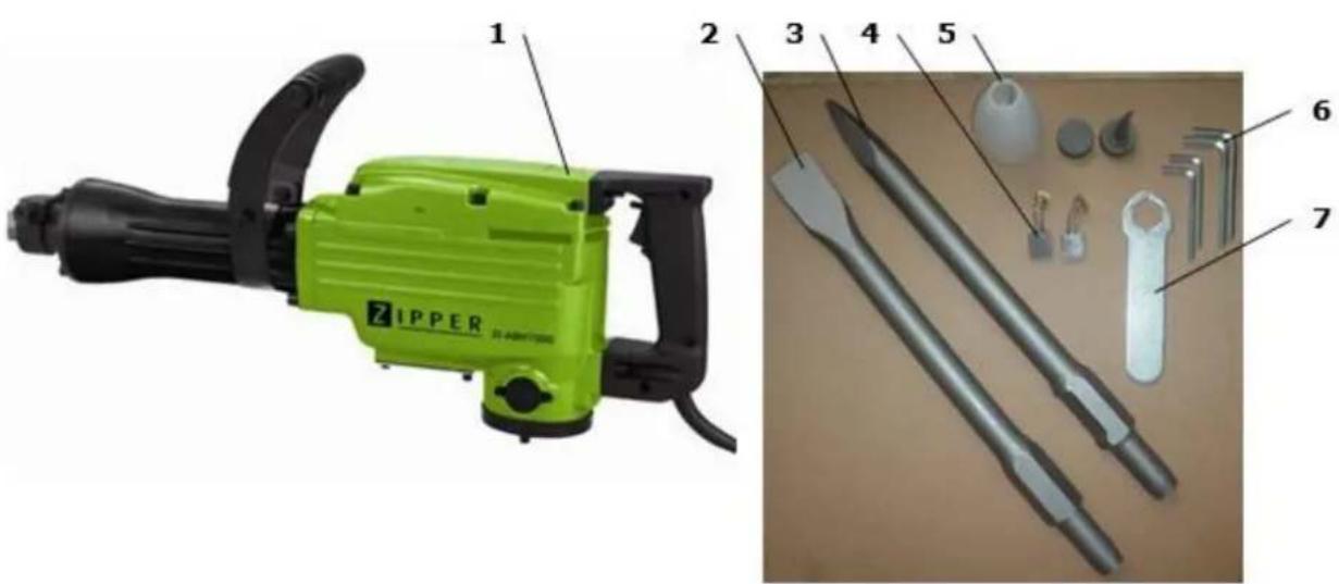
13.1.1 ZI-ABH1050

natural_image
Green power tool with black handle and labeled component (no visible text or symbols)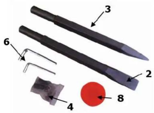
13.1.2 ZI-ABH1500

natural_image
Green ZIPPER-branded power tool with black handle and labeled parts (1 and 2), no visible text or symbols beyond labels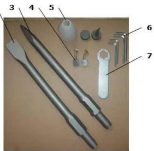
| 1 Demolition hammer | 2 Flat chisel | 3 Point chisel |
| 4 Carbon brushes | 5 Oil filler | 6 Allen key |
| 7 Spanner | 8 Grease |
The range of accessories may differ depending on the model.
14 OPERATION
Device to be operated in a perfect state only. Inspect the device visually every time it is to be used. Check in particular the safety equipment, electrical controls, electric cables and screwed connection for damage and if tightened properly. Replace any damaged parts before operating the device.
14.1 Operation instructions

WARNING
Perform all machine settings with the machine being disconnected from the power supply!

ATTENTION
Excessive pressure may cause material damage!
- When chiseling only slight pressure is required
- Too much pressure unnecessarily overload the motor and cause damage!

NOT I CE
- Use auxiliary handles supplied with the tool
Loss of control can cause personal injury - Hold the machine by insulated gripping surface
The contact with a live wire can cause electric shock - Prior to chiseling into walls, ceilings or floors, ensure there are no electric cables or conduits inside.
- Checking the mains, whether they comply with the relevant national standards and guidelines (especially Assemblies for Construction Sites)
- Use only clean working tool. Lightly lubricate the chisel shank before use with a grease.
14.2 Operation ZI-ABH1050
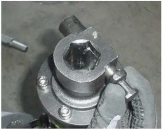
14.2.1 Insert chisel
(1) Rotate the stop lever (3) 180^ clockwise while pulling it toward you.
Next insert the tool shank (1) in the hexagonal hole on the front cover (pic. 1)
(2) Clamp the tool by turning the stop lever (3) half a turn in the opposite direction. (Bild 2)
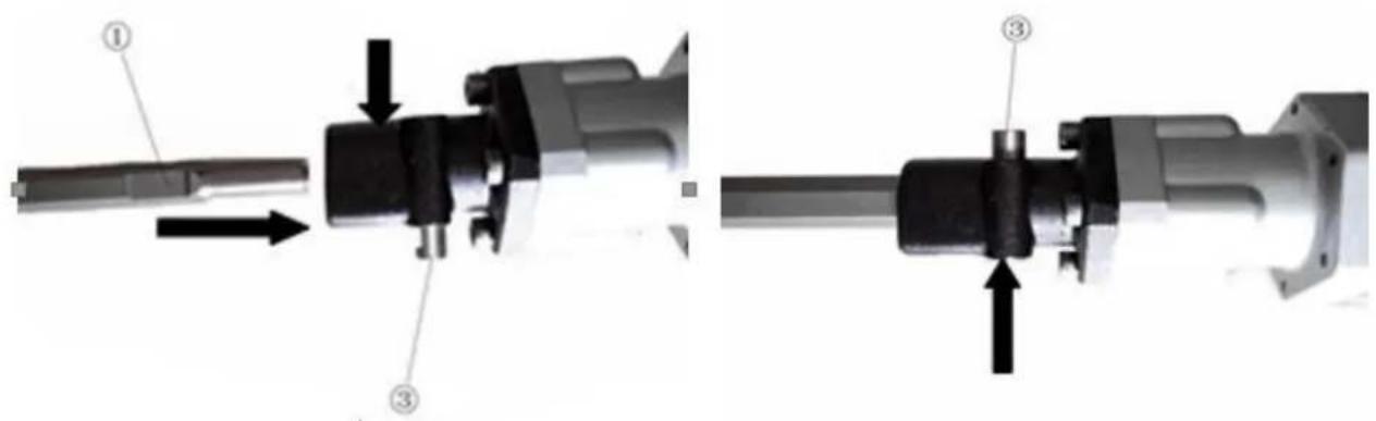
(3) When removing the tool. Follow the above procedure in reverse order.
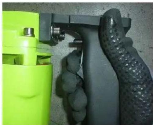
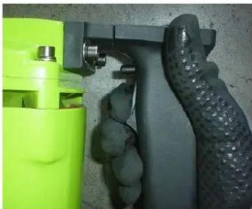
14.2.2 Switch on
- Press the Power push button to the start the engine and set the stroke to move.
- By pressing the locking button can be switched to continuous operation.
natural_image
Close-up of a hand holding a green spray gun and black textured object against a concrete wall (no text or symbols visible)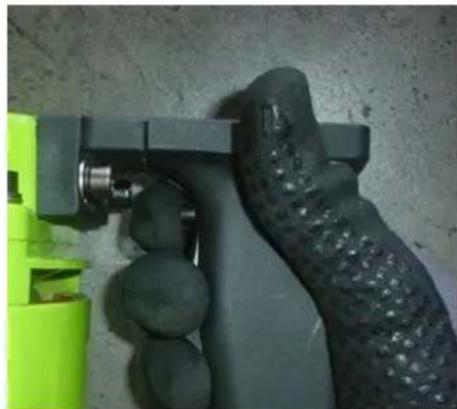
natural_image
Close-up of a hand holding a green and black plastic tool, with no visible text or symbols.14.2.3 Switch off
• Take the pressure off switch push button to stop the stroke.
- For continuous operation, press and release the push button switch to release the fixation.
14.2.4 Filling with oil

WARNING
• The gear motor is supplied without oil!
- Fill gearbox-lubricating oil before starting the E-motor!
Before adding gearbox lubrication oil, disconnect the demolition hammer from the mains.
As an oil tank is installed, the demolition hammer can be used about 20 days to refill without oil. The daily use is about 3 - 4 hours.
Recommended gear oils: 75W-80 75W-90 80W-90 API GL4 API GL5
- Add oil, if in this position (or upright) in the oil level is less than 3mm, or no oil is visible.
- Remove the oil level. Make sure that the rubber seal on the thread fits well and is not damaged when screwing
• After filling of oil drag the oil level again firmly.
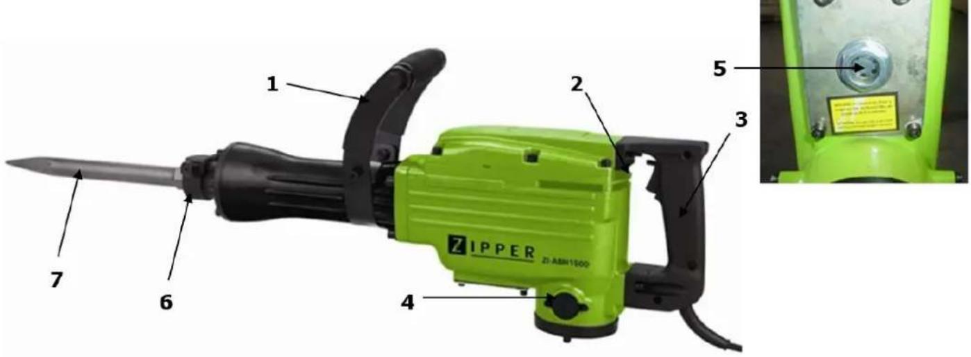
14.3 Operation ZI-ABH1500
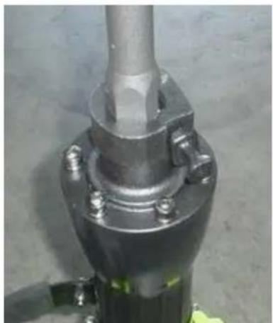
14.3.1 Insert chisel
Clean the tool shank of deposits and grease it lightly one.
- The clamp bolt from the tool shaft pull and turn 90^ clockwise
natural_image
Close-up of a mechanical component with a hexagonal bolt and threaded shaft (no visible text or symbols)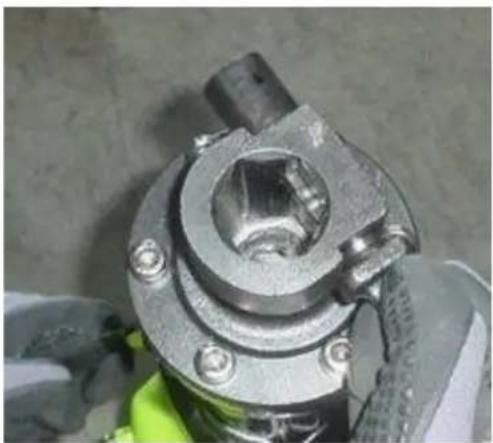
natural_image
Close-up of a mechanical component with bolts and a central hub, partially covered by gloved hands (no visible text or symbols)- Set the tool and rotate the clamp bolt back to 90 degrees and let it snap back into the tool shank.
- Check by pulling the tool if the tool is firmly held in place.
• Tool shank should always be greased before insertion.
- When removing the tool. Follow the above procedure in reverse order.
natural_image
Close-up of a metallic mechanical component with bolts and a central shaft (no visible text or symbols)14.3.2 Switch on
- Press the Power push button to the start the engine and set the stroke to move.
- By pressing the locking button can be switched to continuous operation.
natural_image
Close-up of a hand holding a green spray gun and a black textured object against a concrete wall (no text or symbols visible)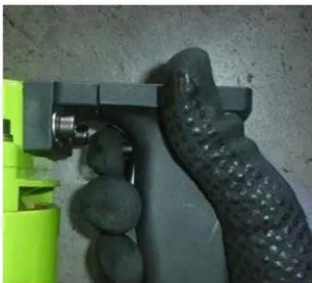
natural_image
Close-up of a hand holding a green and black plastic tool with spherical components, against a plain wall (no text or symbols visible)14.3.3 Switch off
• Take the pressure off switch push button to stop the stroke.
- For continuous operation, press and release the push button switch to release the fixation.
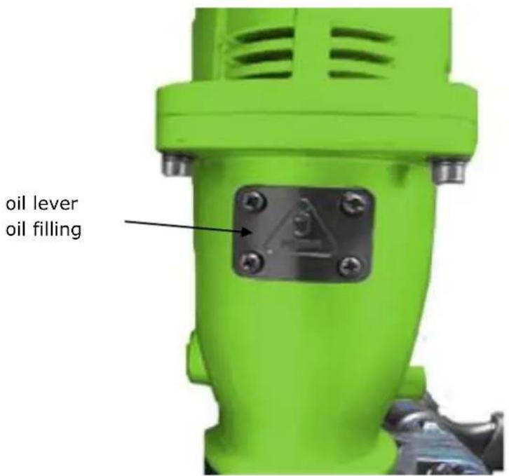
14.3.4 ÖL einfüllen

WARNING
• The gear motor is supplied without oil!
• Fill gearbox-lubricating oil before starting the E-motor!
Before adding gearbox lubrication oil, disconnect the demolition hammer from the mains.
As an oil tank is installed, the demolition hammer can be used about 20 days to refill without oil. The daily use is about 3 - 4 hours.
Recommended gear oils: 75W-80 75W-90 80W-90 API GL4 API GL5
- Add oil, if in this position (or upright) in the oil level is less than 3mm, or no oil is visible.
- Remove the oil level using the supplied Allen wrench. Make sure that the rubber seal on the thread fits well and is not damaged when screwing
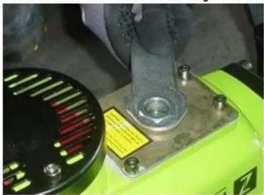
natural_image
Close-up of a green industrial machine with a metallic bolt and screw base, no visible text or symbols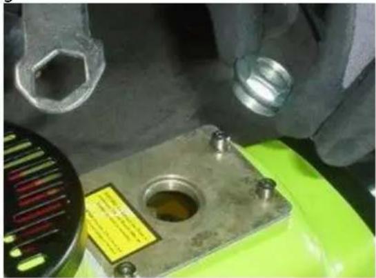
natural_image
Close-up of a mechanical component with a metallic housing and a small cylindrical part, surrounded by hands (no visible text or symbols)- To check, insert the oil level indicator and pull easily fixed.
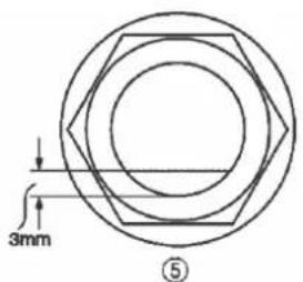
- Oil level should be around 3 mm from the lower edge
• After filling of oil drag the oil level again firmly
15 MAINTENANCE

ATTENTION
Don't clean or do maintenance on the machine while it is still connected to the power supply:
Damages to machine and injuries might occur due to unintended switching on of the machine!
Therefore: Switch the machine off and disconnect it from the power supply be-fore any maintenance works or cleaning is carried out
The machine does not require extensive maintenance. If malfunctions and defects occur, let it be serviced by trained persons only.
Before first operation as well as later on every 100 operation hours you should lubricate all connecting parts (if required, remove beforehand with a brush all swarfs and dust).
Check regularly the condition of the security stickers. Replace them if required.
Check regularly the condition of the machine.
The good condition and perfect adjustment of the guiding rollers is essential for a smooth band guidance and a clean cut.
Store the machine in a closed, dry location.
NOTICE
Clean your machine regularly after every usage – it prolongs the machines lifespan and is a pre-requisite for a safe working environment.
Repair jobs shall be performed by respectively trained professionals only!
15.1 Maintenance plan
| Inspections for the maintenance of the machine | |
| Loose or missing screws | Daily before starting |
| Damage to any part | Daily before starting |
| Clean the machine | Daily before starting |
| Check tool mount to wear of | Every 100 working hours |
| Change carbon brushes | Every 100 working hours |
15.2 Changing the carbon brushes
If the carbon brushes are worn down to the wear limit may result in engine damage. Both carbon brushes should be replaced together. The procedure is ident in both models.
- Loosen the screws of the cover M4X12.
• Take off the cover and unscrew the brush cap. - Remove the carbon brushes.

natural_image
Close-up of a green industrial machine with a yellow screwdriver inserted, showing internal components (no visible text or symbols)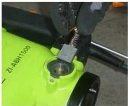
natural_image
Close-up of a green industrial machine component with a metallic screw and central hub (no visible text or symbols)
natural_image
Close-up of a green electric water heater with a screwdriver inserted, no visible text or symbols on the body.• After replacing the carbon brushes rotate the brush cap back on.
- Screw the cover back on.
15.3 Cleaning
After each workshift the machine has to be cleaned. Remove chips etc. with a suitable tool. Do not remove them by hand (cutting injury!). Remove dust as well.

NOTICE
The usage of certain solutions containing ingredients damaging metal surfaces as well as the use of scrubbing agents will damage the machine surface!
Clean the machine surface with a wet cloth soaked in a mild solution
15.4 Disposal
Do not dispose the machine in residual waste. Contact your local authorities information regarding the available disposal options. When you buy at your local dealer for a replacement unit, the latter is obliged to exchange your old.

16 TROUBLE SHOOTING
Disconnect the machine from the power supply prior to any checks performed at the ma-chine itself!
| Trouble | Possible cause | Solution |
| Machine stops or will not start | Machine unpluggedCord damagedOverload tripped | Check all power connectionsChange cableAllow motor to cool and reset by pushing off switch |
| Impact system blocks | High fat friction due to low temperaturesMoving parts are blocked | Warm up the machine in a warm environmentChange damaged parts |
| Drill stucks | Disruptive reinforced steel | Fix new hole |
MANY MALFUNCTIONS AND DEFECTS CAN BE AVOIDED BY LETTING THE MACHINE BE CONNECTED TO YOUR POWER SUPPLY BY A CERTIFIED ELECTRICIAN
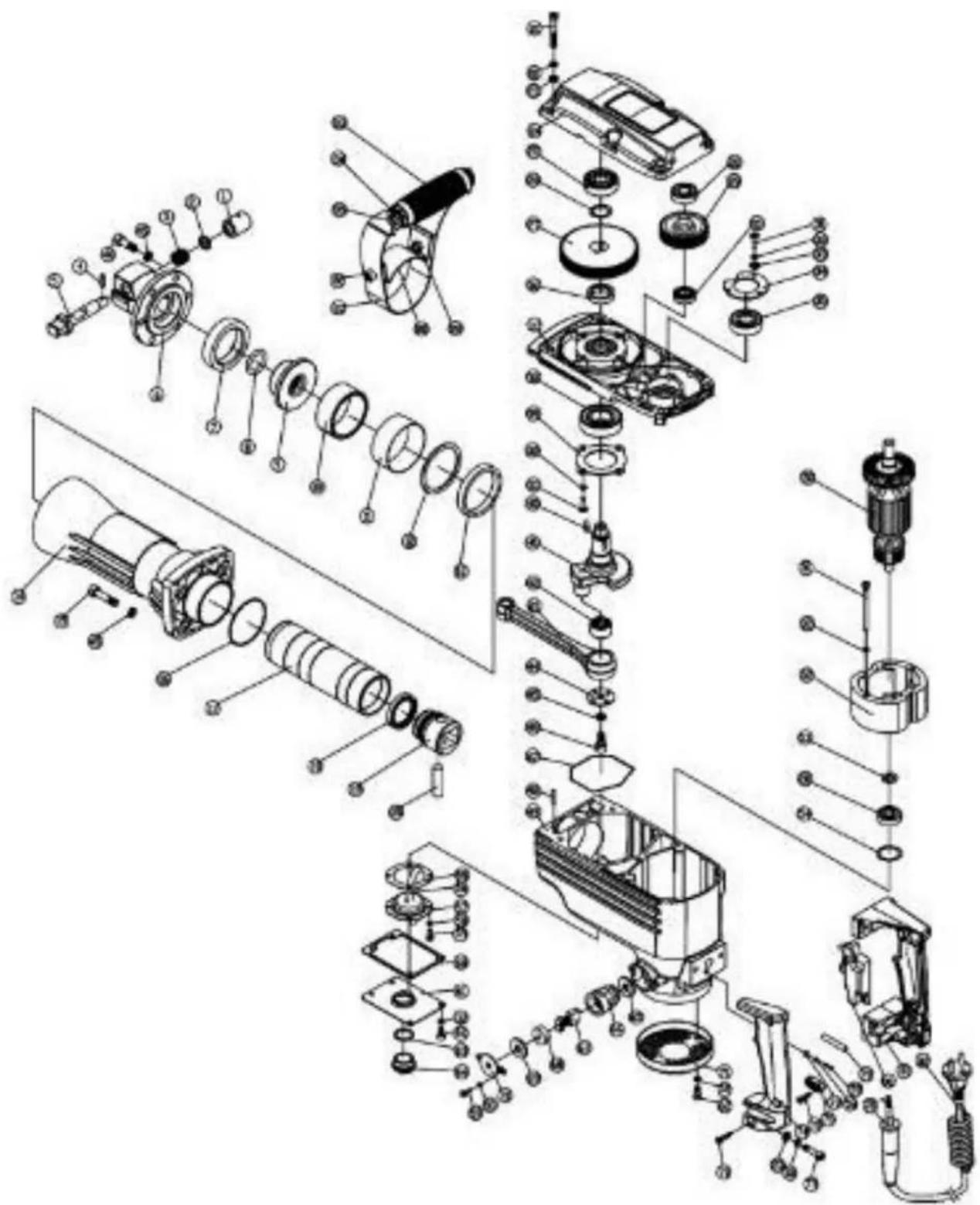
17 ERSATZTEILE / SPARE PARTS
With original ZIPPER spare parts you use parts that are attuned to each other shorten the installation time and elongate your machines lifespan.
IMPORTANT
The installation of other than original spare parts voids the warranty!
So you always have to use original spare parts
When you place a spare parts order please use the service formular you can find in the last chapter of this manual. Always take a note of the machine type, spare parts number and partname. We recommend to copy the spare parts diagram and mark the spare part you need.
You find the order address in the preface of this operation manual.
| NO. | Name | Qty | NO. | Name | Qty | |
| 1 | spring cylindrical pin 3X12 | 1 | 52 | chassis | 1 | |
| 2 | pin shaft | 1 | 53 | steel ring 25 | 1 | |
| 3 | pin spring | 1 | 54 | brush holder safety cover | 2 | |
| 4 | steel ball 8 | 1 | 55 | bearing seat | 1 | |
| 5 | bolt M8X35 | 4 | 56 | bearing 6203 2RS | 1 | |
| 6 | spring washer 8 | 4 | 57 | wava washer 40 | 1 | |
| 7 | the camping seat | 1 | 58 | cylinder sealing pad | 1 | |
| 8 | cylinder case | 1 | 59 | armature | 1 | |
| 9 | intermediate cover gasket | 1 | 60 | motor shell | 1 | |
| 10 | side handle | 1 | 61 | stator | 4 | |
| 11 | six hexagon-head belt M8X130 | 1 | 62 | cross pan head screws M4X5 | 2 | |
| 12 | side handle connecying piece | 2 | 63 | brush holder plate | 1 | |
| 13 | hoop | 1 | 64 | cross head tapping screws ST2.9X10 | 6 | |
| 14 | cylinder | 1 | 65 | shock absorber spring | 2 | |
| 15 | scaling ring 29.5X36.5X3.5 | 2 | 66 | sliding sleeve | 2 | |
| 16 | piston | 1 | 67 | guide pillar | 2 | |
| 17 | connecting rod | 1 | 68 | screw ST4X18 | 3 | |
| 18 | needle bearing HK1210 | 1 | 69 | left handle | 1 | |
| 19 | flat washer 10 | 1 | 70 | right handle | 1 | |
| 20 | cirlip for shaft | 1 | 71 | switch | 1 | |
| 21 | big gear | 1 | 72 | terminal | 1 | |
| 22 | cylindrical pin 4X8 | 2 | 73 | inner wire | 1 | |
| 23 | eccentiec shaft | 1 | 74 | fiberglass pipe Φ7 | 1 | |
| 24 | cirdio for shaft 45 | 1 | 75 | rear cover | 1 | |
| 25 | washer | 2 | 76 | back cover | 1 | |
| 26 | thrust needle roller bearing | 2 | 77 | back cover board | 1 | |
| 27 | needle bearing HK1716 | 2 | 78 | bearing 6201 2RS | 1 | |
| 28 | supporting seat | 1 | 79 | brush holder cover | 2 | |
| 29 | spring washer 5 | 6 | 80 | carbon brush | 2 | |
| 30 | bolt M5X20 | 6 | 81 | brush holder cover | 2 | |
| 31 | gear box | 1 | 82 | brush holder rock | 1 | |
| 32 | the oil cap | 1 | 83 | ring | 1 | |
| 33 | cross pan head screws M4X12 | 8 | 84 | wava washer | 2 | |
| 34 | piston pin | 1 | 85 | power cord | 1 | |
| 35 | 0-ring 2X24 | 1 | 86 | capacity | 1 | |
| 36 | bolt M6X50 | 6 | 87 | switch mounting box | 1 | |
| 37 | spring washer 6 | 17 | 88 | signs | 1 | |
| 38 | washer 6 | 16 | 89 | binding post | 2 |
| 39 | 0-ring 18.5X28.5X5 | 1 |
| 40 | the intermediate lid | 1 |
| 41 | nut 8 | 1 |
| 42 | 0-ring 20.5X34.5X7 | 1 |
| 43 | knob | 1 |
| 44 | knob cap | 1 |
| 45 | anril | 1 |
| 46 | impact piston | 1 |
| 47 | 0-ring Φ4X28 | 2 |
| 48 | stop lever | 1 |
| 49 | the opening sleeve | 1 |
| 50 | the impact cylinder | 1 |
| 51 | bolt M6X25 | 11 |
| 90 | cable clamp | 1 |
| 91 | self tapping screw ST3.9x15 | 2 |
| 92 | cable sheath | 1 |
| 93 | screw M5x25 | 2 |
| 94 | switch mounting box | 1 |
| 95 | crossrecessed countersunk head screws M5X10 | 2 |
17.2.3 ZI-ABH1500
Hereby we declare that the above mentioned machines meet the essential safety and health requirements of the above stated EC directives. Any manipulation or change of the machine not being explicitly authorized by us in advance renders this document null and void.

Christian Eckerstorfer
Techn. Dokumentation / techn. documentation
HOLZMANN-MASCHINEN
Company ZIPPER Maschinen GmbH grants for mechanical and electrical components a warranty period of 2 years for amateur use; and warranty period of 1 year for professional use, starting with the purchase of the final consumer. In case of defects during this period, which are not excluded by paragraph 3, ZIPPER will repair or replace the machine at its own discretion.
2.) Report:
In order to check the legitimacy of warranty claims, the final consumer must contact his dealer. The dealer has to report in written form the occurred defect to ZIPPER. If the warranty claim is legitimate, ZIPPER will pick up the defective machine from the dealer. Returned shippings by dealers which have not been coordinated with ZIPPER, will not be accepted and refused.
3.) Regulations:
a) Warranty claims will only be accepted, when a copy of the original invoice or cash voucher from the trading partner of ZIPPER is enclosed to the machine. The warranty claim expires if the accessories belonging to the machine are missing.
b) The warranty does not include free checking, maintenance, inspection or service works on the machine. Defects due to incorrect usage of the final consumer or his dealer will not be accepted as warranty claims either. Some examples: usage of wrong fuel, frost damages in water tanks, leaving fuel in the tank during the winter, etc.
c) Defects on wear parts are excluded, e.g. carbon brushes, collection bags, knives, cylinders, cutting blades, clutches, sealings, wheels, saw blades, splitting crosses, riving knives, riving knife extensions, hydraulic oils, oil/air/fuel filters, chains, spark plugs, sliding blocks, etc.
d) Also excluded are damages on the machine caused by incorrect or inappropriate usage, if it was used for a purpose which the machine is not supposed to, ignoring the user manual, force majeure, repairs or technical manipulations by not authorized workshops or by the customer himself, usage of non-original ZIPPER spare parts or accessories.
e) After inspection by our qualified personnel, resulted costs (like freight charges) and expenses for not legitimated warranty claims will be charged to the final customer or dealer.
f) In case of defective machines outside the warranty period, we will only repair after advance payment or dealer's invoice according to the cost estimate (incl. freight costs) of ZIPPER.
g) Warranty claims can only be granted for customers of an authorized ZIPPER dealer who directly purchased the machine from ZIPPER. These claims are not transferable in case of multiple sales of the machine.
4.) Claims for compensation and other liabilities:
The liability of company ZIPPER is limited to the value of goods in all cases. Claims for compensation because of poor performance, lacks, damages or loss of earnings due to defects during the warranty period will not be accepted. ZIPPER insists on its right to subsequent improvement of the machine.
Product experience form
We observe the quality of our delivered products in the frame of a Quality Management policy.
Your opinion is essential for further product development and product choice. Please let us know about your:
- Impressions and suggestions for improvement.
- experiences that may be useful for other users and for product design
- Experiences with malfunctions that occur in specific operation modes
We would like to ask you to note down you experiences and observations and send them to us via FAX, E-Mail or by post:
Name / name:
Produkt / product:
Kaufdatum / purchase date:
Erworben von / purchased from:
E-Mail/ e-mail:
Please describe amongst others in the problem:
What has cause the problem/defect, what was the last activity before you noticed the problem/defect?
For electrical problems: Have you had checked you electric supply and the machine already by a certified electrician?
3. Bitte beachten
Additional information
INCOMPLETELY FILLED SERVICE FORMS CANNOT BE PROCESSED! FOR GUARANTEE CLAIMS PLEASE ADD A COPY OF YOUR ORIGINAL SALES / DELIVERY RECEIPT OTHERWISE IT CANNOT BE ACCEPTED. FOR SPARE PART ORDERS PLEASE ADD TO THIS SERVICE FORM A COPY OF THE RESPECTIVE EXPLODED DRAWING WITH THE REQUIRED SPARE PARTS BEING MARKED CLEARLY AND UNMISTAKABLE. THIS HELPS US TO IDENTIFY THE REQUIRED SPARE PARTS FASTLY AND ACCEL- LERATES THE HANDLING OF YOUR INQUIRY.