
C800 - Garage door Hornbach - Free user manual and instructions
Find the device manual for free C800 Hornbach in PDF.

| Product type | Garage door opener device |
| Brand | Hornbach |
| Model | C800 |
| Rated voltage | 220-240 V~ / 50 Hz |
| Rated power | 120 W |
| Standby power | 6 W |
| Protection rating | IP20 |
| Protection class | II (reinforced insulation) |
| Weight | 4.2 kg |
| Temperature range | -20 to +45 °C |
| Max. pull force | 800 N |
| Speed | 0.15 m/s |
| Sound level | <70 dB(A) |
| Continuous operation time | 4 min |
| Service life | 25,000 cycles |
| Max. compatible door dimensions | 4880 x 2200 mm |
| Max. door weight | 116 kg |
| Min. ceiling distance - highest door point | 150 mm |
| Battery type (remote control) | L828 (27A) 12V |
| Battery type (wall control) | CR2032 |
| Radio frequency | 433.92 MHz |
| Radio range (open field) | 25 m |
| Lighting | LED (user non-replaceable) |
| Maintenance and cleaning | Wipe with a soft, damp cloth; mild detergent possible, no alcohol or petroleum |
| Spare parts and repairability | Contact your HORNBACH store for service and parts; user-replaceable batteries; other repairs by a qualified technician |
| General information | Intended use: private garage doors, not commercial use; monthly test of safety reversal system mandatory |
Frequently Asked Questions - C800 Hornbach
User questions about C800 Hornbach
0 question about this device. Answer the ones you know or ask your own.
Ask a new question about this device
Download the instructions for your Garage door in PDF format for free! Find your manual C800 - Hornbach and take your electronic device back in hand. On this page are published all the documents necessary for the use of your device. C800 by Hornbach.
USER MANUAL C800 Hornbach
D GARAGENTORANTRIEB FÜR SEKTIONALTORE | Montage- und Gebrauchsanweisung
F DISPOSITIF D'OUVERTURE DE PORTE DE GARAGE SECTIONNELLE | Manuel d'installation et de l'utilisateur
I APRIPORTA PER GARAGE SEZIONALI | Manuale d'installazione e d'uso
NL OPENER VOOR SECTIONALE GARAGEDEUR | Installatie- en gebruiksaanwij zing
S TAKSKJUTPORTSMOTOR | Installations- och bruksanvisning
CZ OTEVÍRÁNÍ SEKČNÍCH GARÁŽNÍCH VRAT | Montážní a uživatelský manuál
SK OTVÁRAČ SEKČNÝCH GARÁŽOVÝCH DVERÍ | Inštalačná a používatelská príručka
RO INSTALATIE DE DESCHIDERE PENTRU USI SECTIONALE DE GARAJ | Manual de instalare și utilizare
GB SECTIONAL GARAGE DOOR OPENER | Installation and User Manual
Vielen Dank!
natural_image
Product assembly of a metal frame with attached clamps and two separate metal brackets (no text or symbols visible)natural_image
Exploded view of automotive component parts including metal brackets, lockers, and car keys (no text or symbols)natural_image
3D rendering of a modern metal roof structure with support beams and a grid-patterned floor (no text or symbols)2
Torspalt prüfen
natural_image
Technical diagram of a metal structural assembly with multiple supports and mounting holes (no text or symbols)
VORSICHT
natural_image
Technical illustration of a metal beam with screws and a 2x magnified inset showing internal components (no text or symbols)5
Motorkopf
natural_image
Mechanical assembly with metal frame and wiring, no visible text or symbols6
natural_image
3D rendering of a wall-mounted storage unit with horizontal shelves and corner brackets (no text or symbols)9
natural_image
Close-up of a metallic mechanical component with internal parts and a tool, no visible text or symbols12
natural_image
Close-up of a metallic mechanical component with a triangular clip and internal structure (no visible text or symbols)13
natural_image
Technical illustration of a mechanical assembly with multiple components and a close-up view of a component (no text or symbols present)15
Torverstärkung

VORSICHT
natural_image
Exterior view of a metal shelving unit with horizontal supports and a vertical support bracket (no text or symbols)16a
natural_image
Mechanical assembly diagram showing a metal frame with a hanging hook and a downward arrow indicating motion (no text or symbols)18
natural_image
Technical diagram of a metal bracket with mounting holes and bolts, mounted on a horizontal panel (no text or symbols visible)19
22
Stromanschluss
natural_image
Close-up of a black cable inserted into a white electrical socket (no text or symbols visible)Programmierung
1
natural_image
Exterior view of a modern building roof structure with a vertical arrow indicating direction (no text or symbols)
natural_image
Interior view of a room with ceiling grilles and a wall-mounted panel, showing a downward arrow indicating compression or displacement (no text or symbols)3
natural_image
Close-up of a white electronic device with a button and labeled part (4), no readable text or symbols beyond the label.1.

2.
< 10 Sek. < 10 Sek.
natural_image
Close-up of a white computer mouse button with an orange power button and arrow indicator (no text or symbols)natural_image
Exterior view of a modern office building (no signage)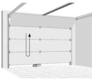
natural_image
3D diagram of a U-shaped pipe or channel structure inside a room with ceiling grilles and a small rectangular base (no text or symbols)natural_image
3D diagram showing a switch inside a wall-mounted device and its close-up view of the door (no text or symbols present)natural_image
Exploded view of a handheld electronic device showing internal components like battery pack, switch, and connector (no text or symbols visible)Directive machines 2006/42/CE
Directive RED 2014/53/UE
Spectre (Art. 3(2)): EN 300 220-2 V3.1.1:2017
natural_image
Exploded view of automotive component parts including metal brackets, gear tools, and car keys (no text or symbols)Supports Kit de vissage Commandes
natural_image
3D rendering of a modern indoor space with a metal roof and tiled floor (no text or symbols)2
natural_image
Technical diagram of a metal structural assembly with multiple supports and mounting holes (no text or symbols)
ATTENTION
natural_image
Technical illustration of a metal beam with screws and a close-up inset showing internal components (no text or symbols)5
Unité de moteur
natural_image
Mechanical assembly with metal bracket and cable, no visible text or symbols6
natural_image
3D rendering of a wall-mounted storage unit with horizontal shelves and corner brackets (no text or symbols)9
natural_image
Close-up of a metallic mechanical component with internal parts and a tool, no visible text or symbols12
natural_image
Close-up of a metallic mechanical component with a triangular clip and internal structure (no visible text or symbols)13
natural_image
Technical illustration of a mechanical assembly with multiple components and a close-up view of a component (no text or symbols present)15
natural_image
Exterior view of a metal shelving unit with horizontal supports and a vertical support bracket (no text or symbols)16a
natural_image
Mechanical assembly diagram showing a metal frame with a hanging hook and a downward arrow indicating motion (no text or symbols)18
natural_image
Technical diagram of a metal bracket with mounting holes and bolts, mounted on a horizontal panel (no text or symbols visible)19
natural_image
Mechanical assembly diagram showing a lever with labeled points A and B, and a hanging component (no text or symbols beyond labels)21
Installer la commande murale
22
natural_image
Close-up of a black cable inserted into a white electrical outlet socket (no text or symbols visible)Programmation
1
natural_image
Simple line drawing of a roof structure with a downward arrow indicating direction (no text or symbols)3.
natural_image
Interior view of a room with horizontal paneling and ceiling light, showing a downward arrow indicating a decrease (no text or symbols present)5.
natural_image
Close-up of a white electronic device with a button and labeled part (4), no readable text or symbols beyond the number.1.
2.
natural_image
Exterior view of a modern metal warehouse shelter with a small rectangular block on the floor (no signage or text)
natural_image
3D diagram of a U-shaped pipe or channel inside a rectangular chamber, with no visible text or symbolsnatural_image
3D diagram showing a switch inside a wall-mounted device and its close-up view of the door (no text or symbols present)natural_image
Exploded view of a handheld electronic device showing internal components like battery pack, switch, and connector (no text or symbols visible)natural_image
Exploded view of automotive component parts including metal brackets, lockers, and car keys (no text or symbols)natural_image
3D rendering of a modern metal roof structure with support beams and tiled floor (no text or symbols)2
natural_image
Technical diagram of a metal beam supported by two parallel plates, with bolt holes and dimension label '2x' (no text or symbols beyond the label)
ATTENZIONE
natural_image
Technical illustration of a metal beam with screws and a 2x magnified inset showing internal components (no text or symbols)5
Motore
natural_image
Mechanical assembly with metal frame and wiring, no visible text or symbols6
natural_image
3D rendering of a wall-mounted storage unit with horizontal shelves and corner brackets (no text or symbols)9
natural_image
Close-up of a metallic mechanical component with internal parts and a tool, no visible text or symbols12
natural_image
Close-up of a metallic mechanical component with a triangular clip and internal structure (no visible text or symbols)13
natural_image
Technical illustration of a mechanical assembly with multiple components and a close-up view of a component (no text or symbols present)15
natural_image
Exterior view of a metal shelving unit with horizontal supports and a vertical support bracket (no text or symbols)16a
natural_image
Mechanical assembly diagram showing a metal frame with a hanging hook and a downward arrow indicating motion (no text or symbols)natural_image
Technical diagram of a metal bracket with mounting holes and bolts, mounted on a horizontal panel (no text or symbols visible)19
22
natural_image
Close-up of a black cable inserted into a white electrical socket (no text or symbols visible)Programmazione
1
natural_image
Exterior view of a modern building roof structure with a vertical arrow indicating direction (no text or symbols)
natural_image
Interior view of a room with ceiling grilles and a wall-mounted panel, showing a downward arrow indicating compression or displacement (no text or symbols)3
natural_image
Close-up of a white electronic device with a button and labeled point '4' (no text or symbols beyond the label)
natural_image
Exterior view of a modern office building (no signage)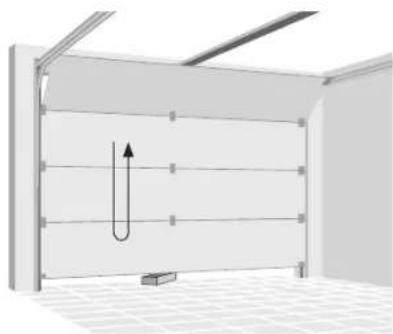
natural_image
3D diagram of a U-shaped pipe or channel structure inside a room with ceiling grilles and a small rectangular block at the bottom (no text or symbols)Funzionamento

AVVERTENZA
natural_image
3D diagram showing a switch inside a wall-mounted device and its close-up view of the door (no text or symbols present)natural_image
Exploded view of a handheld electronic device showing internal components like battery pack, switch, and connector (no text or symbols visible)natural_image
Three types of electrical components: rail-set, rail connectors, and deurarm, shown in separate views (no text or symbols on parts)

natural_image
Exploded view of automotive component parts including metal brackets, gear tools, and car keys (no text or symbols)natural_image
3D rendering of a modern metal roof structure with arched windows and a grid-patterned floor (no text or symbols)2
natural_image
Technical diagram of a metal beam supported by two parallel plates, with no visible text or symbols
OPGELET
natural_image
Technical illustration of a metal beam with screws and a 2x magnified inset showing internal components (no text or symbols)5
Motoreenheid
natural_image
Mechanical assembly with metal bracket and cable, no visible text or symbols6
De riem spannen
natural_image
3D rendering of a wall-mounted storage unit with horizontal shelves and corner brackets (no text or symbols)9
natural_image
Close-up of a metallic mechanical component with internal parts and a tool, no visible text or symbols12
natural_image
Close-up of a metallic mechanical component with a triangular clip and internal structure (no visible text or symbols)13
natural_image
Technical illustration of a mechanical assembly with multiple components and cross-sectional views (no text or symbols)15
Deurversterking

OPGELET
natural_image
Exterior view of a metal shelving unit with horizontal supports and a vertical support bar (no text or symbols)16a
natural_image
Mechanical assembly diagram showing a metal frame with a hanging hook and a downward arrow indicating motion (no text or symbols)18
natural_image
Technical diagram of a metal bracket with mounting holes and bolts, mounted on a horizontal panel (no text or symbols visible)19
22
Voeding aansluiten
natural_image
Close-up of a white electrical outlet with a black cable inserted, showing the socket and socket (no text or symbols visible)Programmeren
1
natural_image
Simple line drawing of a roof structure with a vertical arrow indicating upward motion (no text or symbols)
natural_image
Interior view of a room with horizontal paneling and ceiling light, showing a downward arrow indicating a decrease (no text or symbols present)3
Bediening koppelen
LED-indicator 1
Knop 1 2
Knop 2 3
Activeringsknop 4
1.
natural_image
Close-up of a white electronic device with a button and labeled part (4), no readable text or symbols beyond the label.1.
2.

natural_image
Exterior view of a modern office building (no signage)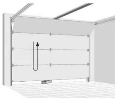
natural_image
3D diagram of a U-shaped pipe or channel structure inside a rectangular chamber, with no visible text or symbols.natural_image
3D diagram showing a switch inside a wall-mounted device and its corresponding view of a U-shaped door (no text or symbols present)Batterij vervangen van afstandsbedie- ning
natural_image
Exploded view of a handheld electronic device showing internal components like battery pack, switch, and connector (no text or symbols visible)Bediening resetten
natural_image
Three metal components: skensats, skenanslutningar portarm, and two separate curved metal parts (no text or symbols visible)
natural_image
Exploded view of automotive component parts including metal brackets, gear tools, and car keys (no text or symbols)Konsoler Skruvset Reglage
Tekniska data
Garageportsöppnare
Märkspänning 220-240 V\~/50 Hz
Märkeffekt 120 W
Standbyeffekt 6 W
natural_image
3D rendering of a modern metal roof structure with arched supports and grid-patterned floor (no text or symbols)2
Kontrollera portspelet
natural_image
Technical diagram of a metal beam supported by two vertical posts, showing structural components and mounting points (no text or symbols)
FÖRSIKTIG
natural_image
Technical illustration of a metal beam with screws and a close-up inset showing internal components (no text or symbols)5
Motorenhet
natural_image
3D rendering of a mechanical assembly with metal brackets and wiring, no visible text or symbols6
Remspänning
natural_image
3D rendering of a room corner with horizontal shelves and vertical supports (no text or symbols)9
natural_image
Close-up of a mechanical assembly with metal components and a tool, no visible text or symbols12
natural_image
Close-up of a metallic mechanical component with a triangular clip and internal structure (no visible text or symbols)13
natural_image
Technical illustration of a mechanical assembly with multiple components and cross-sectional views (no text or symbols)15
Portförstärkning

FÖRSIKTIG
natural_image
Exterior view of a metal shelving unit with horizontal railings and a vertical support bracket (no text or symbols)16a
natural_image
Mechanical assembly diagram showing a metal frame with a hanging hook and a downward arrow indicating motion (no text or symbols)18
natural_image
Technical diagram of a metal bracket with mounting holes and bolts, mounted on a horizontal panel (no text or symbols visible)19
natural_image
Mechanical assembly diagram showing a lever with labeled points A and B, and a hanging component (no text or symbols beyond labels)21
22
Strömanslutning
natural_image
Close-up of a white electrical outlet with a black cable inserted, showing the socket and socket (no text or symbols visible)Programmering
1
Programmeringsknappar på motorenheten:
- (Nerknapp) 1
+(Uppknapp)2
Inställningsknapp 3
Kodknapp 4

2
natural_image
Simple line drawing of a roof structure with a vertical arrow indicating upward motion (no text or symbols)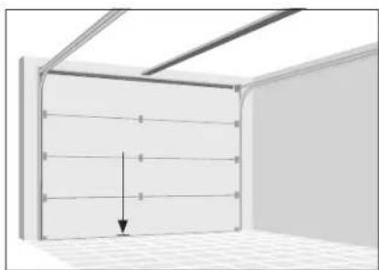
natural_image
Interior view of a room with horizontal paneling and ceiling light, showing a downward arrow indicating a decrease (no text or symbols present)3
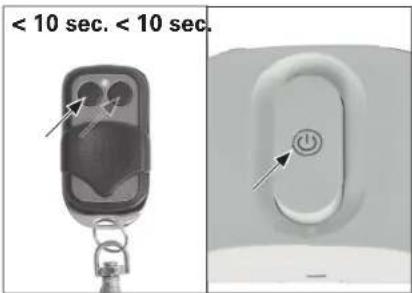
Parningskontroller
LED-indikator 1
Knapp 1 2
Knapp 2 3
Aktiveringsknapp 4
1.
Tryck på kodknappen tills LED 1 lyser konstant.
2.
natural_image
Close-up of a white electronic device with a button and labeled part (4), no readable text or symbols beyond the label.1.

2.
< 10 s. < 10 s.

natural_image
Close-up of a white electronic button with an arrow pointing to the power button (no text or symbols visible)natural_image
Exterior view of a modern office building (no signage)
natural_image
3D diagram of a U-shaped pipe or channel inside a room with ceiling grilles and a small rectangular block at the bottom (no text or symbols)Användning

WARNING
natural_image
3D diagram showing a switch inside a wall-mounted device with an arrow pointing to the switch (no text or symbols present)Byta batteri i fjärrkontrollen
natural_image
Exploded view of a handheld electronic device showing internal components like battery pack, switch, and connector (no text or symbols visible)Radera kontroller
TYTO POKYNY USCHOVEJTE.
natural_image
Product assembly of a metal frame with attached clamps and two separate metal brackets (no text or symbols visible)Sada kolejnice
Spojky kolejnice Rameno vrat

natural_image
Exploded view of automotive component parts including metal brackets, gear tools, and car keys (no text or symbols)natural_image
3D rendering of a metal-framed storage or support structure with grid pattern at the base (no text or symbols)2
natural_image
Technical diagram of a metal beam supported by vertical supports and a 2x load, showing structural details without any text or symbols.
POZOR
natural_image
Technical illustration of a metal I-beam with screws and screw holes, shown alongside an inset close-up of its internal components (no text or symbols)5
Jednotka motoru
natural_image
3D rendering of a mechanical device with metal brackets and a cable, no visible text or symbols6
Napínání remene
natural_image
3D rendering of a wall-mounted storage unit with horizontal shelves and corner brackets (no text or symbols)9
natural_image
Close-up of a metallic mechanical component with internal parts and a tool, no visible text or symbols12
natural_image
Close-up of a metallic mechanical component with a triangular clip and internal structure (no visible text or symbols)13
natural_image
Technical illustration of a mechanical assembly with multiple components and a close-up view of a component (no text or symbols present)15
Vyztužení vrat

POZOR
natural_image
Exterior view of a metal shelving unit with vertical supports and horizontal rails (no text or symbols)16a
Montáž držáku vrat
natural_image
Mechanical assembly diagram showing a metal frame with a hanging hook and a downward arrow indicating motion (no text or symbols)18
natural_image
Technical diagram of a metal bracket with mounting holes and bolts, mounted on a horizontal panel (no text or symbols visible)19
22
natural_image
Close-up of a white electrical outlet with a black cable inserted (no text or symbols visible)Programování
1
natural_image
Simple line drawing of a roof structure with a vertical arrow indicating upward motion (no text or symbols)
natural_image
Interior view of a room with horizontal paneling and ceiling light, showing a downward arrow indicating a decrease (no text or symbols present)3
Spárovaná ovládání
Kontrolka led 1
Tlačítko 1 2
Tlačítko 2 3
Tlačítko aktivace 4
1.
natural_image
Close-up of a white electronic device with a button and labeled point '4' (no text or symbols beyond the label)1.
2.
natural_image
Exterior view of a modern office building (no signage)
natural_image
Diagram of a U-shaped structure inside a room with ceiling grilles and a small rectangular block at the bottom (no text or symbols)Provoz

VAROVÁNÍ
natural_image
Diagram showing a switch inside a wall-mounted device and its open lid, with an arrow indicating the switch's direction (no text or symbols present)natural_image
Exploded view of a handheld electronic device showing internal components like battery pack, switch, and connector (no text or symbols visible)Vymazání ovládání
1.
DÔLEŽITÉ BEZPEČNOSTNÉ POKYNY
UPOZORNENIE – Z DÔVODOV BEZPEČNOSTI JE DÔLEŽITÉ, ABY STE SA RIADILI PODL'A TÝCHTO POKYNOV
TIETO POKYNY SI ODLOŽTE.
DÔLEŽITÉ BEZPEČNOSTNÉ POKYNY
Dôležité pokyny na inštaláciu
natural_image
Exploded view of automotive component parts including metal brackets, lockers, and car keys (no text or symbols)natural_image
3D rendering of a modern metal roof structure with support beams and tiled floor (no text or symbols)2
natural_image
Technical diagram of a metal structural assembly with multiple supports and mounting holes (no text or symbols)
POZOR
natural_image
Technical illustration of a metal beam with screws and a 2x magnified inset showing internal components (no text or symbols)5
Motorová jednotka
natural_image
Mechanical assembly diagram showing a metal rod with four bolts and a cable, no text or symbols present6
Napnutie remeňa
natural_image
3D rendering of a room corner with horizontal shelves and a curved ceiling fixture (no text or symbols)9
natural_image
Close-up of a metallic mechanical component with internal parts and a tool, no visible text or symbols12
Zopnite vzpery závlačky, aby sa zaistila na mieste.
natural_image
Close-up of a metallic mechanical component with a triangular clip and internal structure (no visible text or symbols)13
Zdvihnite kolajničku na konci s motorom až k stropu. Úplne otvorte garážové dvere. Na horný koniec garážových dverí umiestnite dosku (hrúbka 4 cm) a položte na ňu kolajničku.
14
natural_image
Technical illustration of a mechanical assembly with multiple components and cross-sectional views (no text or symbols)15
Vystuženie dverí

POZOR
natural_image
Exterior view of a metal shelving unit with vertical supports and horizontal rails (no text or symbols)16a
natural_image
Mechanical assembly diagram showing a metal frame with a hanging hook and a downward arrow indicating motion (no text or symbols)18
natural_image
Technical diagram of a metal bracket with mounting holes and bolts, mounted on a horizontal panel (no text or symbols visible)19
22
Pripojenie napájania
natural_image
Close-up of a black cable inserted into a white electrical outlet socket (no text or symbols visible)Programovanie
1
natural_image
Simple line drawing of a roof structure with a vertical arrow indicating upward motion (no text or symbols)
natural_image
Interior view of a room with horizontal paneling and ceiling light, showing a downward arrow indicating a decrease (no text or symbols present)3
natural_image
Close-up of a white electronic device with a circular button and labeled number 4 (no text or symbols beyond the label)1.

2.
natural_image
Exterior view of a modern office building (no signage)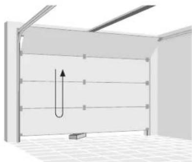
natural_image
Diagram of a U-shaped structure inside a room with ceiling grilles and a small rectangular block at the bottom (no text or symbols)Obsluha

UPOZORNENIE
natural_image
Diagram showing a switch mechanism inside a plastic door frame, with an arrow indicating the process (no text or symbols present)natural_image
Exploded view of a smart home electronic device showing internal components like battery pack, switch, and carabiner (no text or symbols visible)natural_image
Exploded view of automotive component parts including metal brackets, lockers, and car keys (no text or symbols)natural_image
3D rendering of a modern metal roof structure with arched supports and grid-patterned floor (no text or symbols)2
Verifi carea fantei uşii
natural_image
Technical diagram of a metal beam supported by two vertical posts, showing structural components and mounting points (no text or symbols)4
Montare angrenaj
natural_image
Technical illustration of a metal beam with screws and a 2x load, showing internal components and assembly (no text or symbols)5
Unitate motor
natural_image
Mechanical assembly with metal frame and wiring, no visible text or symbols6
natural_image
3D rendering of a wall-mounted storage unit with horizontal shelves and corner brackets (no text or symbols)9
natural_image
Close-up of a metallic mechanical component with internal parts and a tool, no visible text or symbols12
natural_image
Close-up of a metallic mechanical component with a triangular clip and internal structure (no visible text or symbols)13
natural_image
Technical illustration of a mechanical assembly with multiple components and a close-up view of a component (no text or symbols present)15
Ranforsarea usii

PRECAUTIE:
natural_image
Exterior view of a metal shelving unit with horizontal railings and a vertical support bracket (no text or symbols)16a
Montarea consolei uşii
natural_image
Mechanical assembly diagram showing a metal frame with a hanging hook and a downward arrow indicating motion (no text or symbols)18
natural_image
Technical diagram of a metal bracket with mounting holes and bolts, mounted on a horizontal panel (no text or symbols visible)19
22
Conectarea la sursa de alimen- tare
natural_image
Close-up of a white electrical outlet with a black cable inserted (no text or symbols visible)Programare
1
natural_image
Exterior view of a modern building roof structure with a vertical arrow indicating direction (no text or symbols)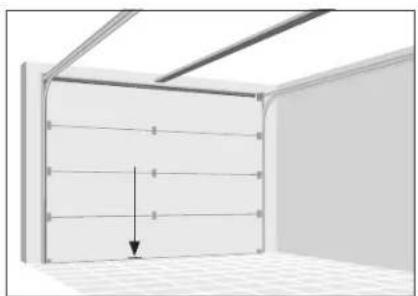
natural_image
Interior view of a room with ceiling grilles and a wall-mounted panel, showing a downward arrow indicating compression or displacement (no text or symbols)3
natural_image
Close-up of a white electronic device with a button and labeled point '4' (no text or symbols beyond the label)1.
2.
natural_image
Exterior view of a modern office building (no signage)
natural_image
3D diagram of a U-shaped pipe or channel structure inside a room with ceiling grilles and a small rectangular block at the bottom (no text or symbols)natural_image
Diagram showing a switch mechanism inside a plastic door frame, with an arrow indicating the process (no text or symbols present)natural_image
Exploded view of a handheld electronic device showing internal components like battery pack, switch, and connector (no text or symbols visible)We are convinced that this garage door opener will exceed your expectations and wish you joy while using it.
Read the instructions before installing or using the garage door opener. Keep it close to the garage door after installation and observe the safety instructions.
Service
In case of service requests or spare parts, please contact your local HORNBACH store.
Symbols

Please read this user manual carefully and keep it for further reference.

Warning of accident and injury to persons and serious damage to property.

2 persons required.

Do not use outdoors or in damp environments.

Protection class II (enforced insulation).

Temperature range -20 to 45 °C

Keep children away when the door is moving. Never allow children to walk or run under moving door. Never allow children to use door opener controls. Always keep moving door within sight. If person is trapp<ed under door, push wall control button or use emergency release.

If door opener doesn't work, pull red emergency release knob and open door manually.

WARNING
Indicates a potentially dangerous situation which, if not protected against, could result in death or serious (irreversible) injuries.

CAUTION
Indicates a potentially hazardous situation which can result in minor or moderate injury or damage to the product or equipment.
Table of content
| Service | 194 |
| Symbols | 194 |
| Intended use 194 | |
| Important safety instructions 195 | |
| Declaration of conformity 197 | |
| Overview | 198 |
| Components | 198 |
| Scope of delivery 198 | |
| Technical data 200 | |
| Installation | 201 |
| Required accessories 201 | |
| Preparation | 201 |
| Programming | 210 |
| Safety reversal system test 212 | |
| Operation | 213 |
| Maintenance | 214 |
| Maintenance work by operator 214 | |
| Monthly maintenance 214 | |
| Cleaning | 214 |
| Battery change of wall control | 215 |
| Battery change of remote control | 215 |
| Erasing controls | 215 |
| Troubleshooting | 216 |
| Disposal | 216 |
Intended use
This garage door opener is intended for the operation of garage doors in the private sector, matching the specifications given in section technical data. The garage door opener may only be used in dry rooms. The opener is not to be used with doors having openings exceeding 50 mm in diameter or having edges or protruding parts a person could grip or stand on. The garage door opener is not intended for commercial use or use in public space.
Any other use or modification to the garage door opener is considered as improper use and could cause considerable dangers.

WARNING
- Carefully read this installation and user manual prior to the installation and use of the product.
- Observe the installation requirements and installation methods for a proper and safe installation.
- Lack of maintenance can lead to unsafe operation.

WARNING
Manual release test
- Close garage door, then pull down the red emergency release handle. The trolley will disconnect.
- Test door for balance by releasing it at halfway. If balanced, it should stay in place, supported entirely by its springs. If the door falls down, seek professional garage door service.

WARNING
Safety reversal system test
- With the door fully open, place a board with a thickness of 5 cm centered in the way of the door.
- Press remote control push button. When closing, the door MUST reverse when making contact with the board.
- Otherwise do not use the garage door opener any more; instead seek professional assistance for repair.

IMPORTANT SAFETY INSTRUCTIONS
WARNING NOTICE - FOR THE SAFETY OF PERSONS, IT IS IMPORTANT TO FOLLOW THESE INSTRUCTIONS
THESE INSTRUCTIONS ARE TO BE KEPT. Important operation instructions
- Read and follow all warnings and instructions.
· Always keep remote controls out of the reach of children. Children shall not play with the appliance. Cleaning and user maintenance shall not be made by children without supervision.
· This appliance can be used by children aged from 8 years and above and persons with reduced physical, sensory or mental capabilities or lack of experience and knowledge if they have been given supervision or instruction concerning use of the appliance in a safe way and understand the hazards involved. - Only activate the garage door when you clearly see that there are no obstructions to door travel.
· Always keep the garage door in sight until completely closed. No one should cross the path of the moving door. - No one should go under a stopped, partially opened door.
- Watch the moving door and keep people away until the door is completely opened or closed.
- Due to remote control the door may move unexpectedly. No one should cross the path of a moving door.
- If possible, use emergency release handle only when garage door is closed. Otherwise make sure, that the garage doorway is clear of persons and obstructions. Weak or broken springs or an unbalanced door could result in an open door falling rapidly and unexpectedly.
· Never use emergency release handle to pull the garage door open or closed. If rope knot becomes untied, you could fall.
· Frequently examine the installation, in particular check cables, springs and mount-
ings for signs of wear, damage or imbalance. Do not use if repair or adjustment is needed since a fault in the installation or an incorrectly balanced door may cause injury.
· Safety reversal system must be tested monthly and after any adjustments. The garage door must reverse on contact with objects 5 cm above floor level.
· Balance of garage door must be tested monthly. An improperly balanced door may not reverse when required and could result in severe injury or death.
- All repairs to cables, spring assemblies and other hardware must be made by a trained door systems technician.
· Each steel wire rope shall have a safety factor not smaller than 6 (minimum breaking strength/static load of one rope).
- Rope drums shall have a pitch circle diameter (PCD) at least equal to 20 times the rope diameter.
· Always disconnect electric power to garage door opener before making any repairs or removing covers.
· If necessary, call for authorized service.
- Ensure that all safety and danger labels stay fully legible.
- Permanently fix the labels warning against entrapment in a prominent place or near any fixed controls.
· The drive must not be used with a door incorporating a wicket door.
· The drive is not to be used with doors having openings exceeding 50 mm in diameter or having edges or protruding parts a person could grip or stand on.

IMPORTANT SATETY INSTRUCTIONS
Important installation instructions
- Install garage door opener only on properly balanced and lubricated garage door. - Disable all locks connected to the garage door.
- The drive is intended to be installed at least 2.5 m above the floor or other access level.
· Install the actuating member for the manual release at a height less than 1.8 m. If removable, the actuating member should be stored in direct vicinity of the door.
· Never connect garage door opener to power source until instructed to do so.
- Permanently fix the label concerning the manual release adjacent to its actuating member.
· Never wear watches, rings or loose clothing while installing or servicing opener. They could be caught in garage door or opener mechanisms.
- Install wall-mounted garage door control:
- within sight of the garage door.
· out of reach of children at minimum height of 1.5 m).
· away from all moving parts of the door.
- Place entrapment warning label on wall next to garage door control.
- Place manual release/safety reverse test label in plain view on inside of garage door.
- Upon completion of installation, test safety reversal system.
· To avoid serious personal injury or death from electrocution, disconnect all electric and battery power before performing any service or maintenance.
- Warning! Lack of maintenance can lead to unsafe operation.
For use of batteries
· The battery must be removed from the appliance before it is scrapped.
· CAUTION! Explosion hazard when the batteries are not replaced correctly. Only replace by batteries of the same type. Pay attention to the correct polarity.
Do not expose batteries (battery pack or inserted batteries) to excessive heat from sunlight, fire, etc. Protect from mechanical shocks. Keep dry and clean. Keep out of reach of children.
- Do not open, disassemble, cut open, or short-circuit batteries. Do not use old and new batteries together.
- Observe the safety notes and other notes on the battery and its packaging.
- Remove leaking batteries and clean the battery compartment thoroughly. Avoid contact with eyes and skin.
· Do not ingest the battery, chemical burn hazard.
· If you think that batteries might have been swallowed or placed inside any part of the body, seek immediate medical attention.
Declaration of conformity
CE We declare, that the product described in Technical Data:
Garage Door Opener C800
manufactured for:
is in conformity with the following directives:
Machinery Directive 2006/42/EC
RED Directive 2014/53/EU
and in accordance to the following applicable harmonized standards:
EN 60335-2-95:2015/A1:2015
EN 60335-1:2012/A13:2017
EN 62233:2008
AfPS GS 2014:01 PAK
EN 13241:2003/A2:2016
prEN 12635:2015
EN 12635:2015
EN 12453:2017
EN ISO 12100:2010
EN 55014-1:2017
EN 55014-2:2015
EN 55015:2013/A1:2015
EN 61547:2009
EN 61000-3-2:2014
EN 61000-3-3:2013
Draft ETSI EN 301 489-1 V2.2.0:2017
Final Draft ETSI EN 301 489-3 V2.1.1:2017
EN 62479:2010
Spectrum (Art. 3(2)): EN 300 220-2 V3.1.1:2017
The door opener must not be put into service until the garage door system into which it is to be incorporated has been declared in conformity with the provisions of the directives EN 12453, EN 13241 and 2006/42/EC.
ppa. Andrews Back
Andreas Back
Head of Quality Management, environment & CSR
Person authorised to compile the technical file
Bornheim, 12.08.2018
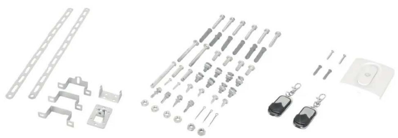
Scope of delivery
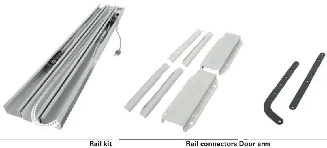
natural_image
Product images of rail components including a rail kit, rail connectors, and door arm (no text or symbols on parts)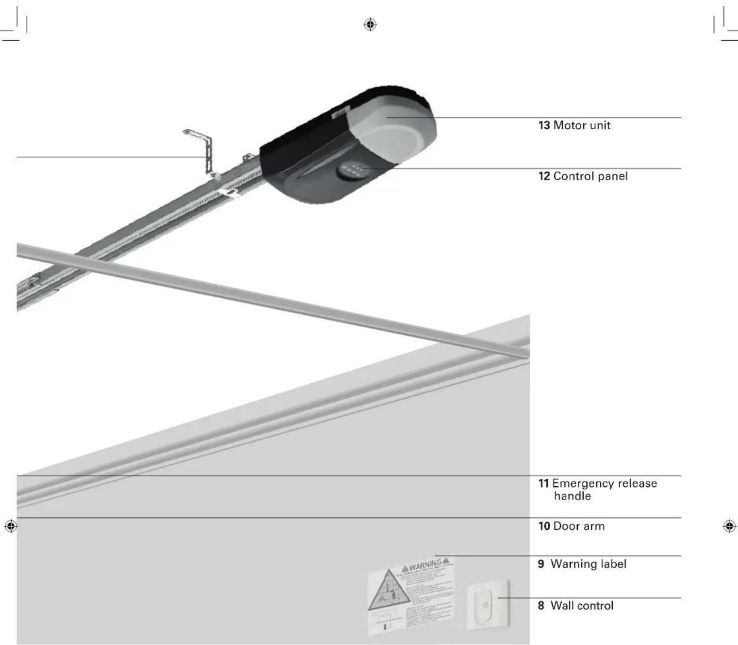

natural_image
Exploded view of automotive component parts including metal brackets, lockers, and car keys (no text or symbols)Brackets Screw kit Controls
Technical data
Garage door opener
Nominal voltage 220-240 V\~/ 50 Hz
Rated power 120 W
Standby power 6 W
Light source LED, not replaceable by user
Protection class IP 20
Degree of protection II
Weight 4.2 kg
Temperature range -20 to +45 °C
Max. pulling force 800 N
Speed 0.15 m/s
LpA <70 dB(A)
Time of continuous operation
Opener service life
4 min
25,000 cycles
Suitable for garage doors, fulfilling all of the following demands:
Setup
Sectional door with horizontal and vertical track, well balanced and equipped with a fall arrester
4880 x 2200 mm
116 kg
Min. distance between ceiling and highest point of travel of the door
150 mm
Wall control
Battery type
CR2032
Frequency range
433.92MHz ±100kHz
Radio range in free-field conditions
25 m
Max. transmitting power
4 dBm
Remote control
Battery type
L828 (27A) 12V
Frequency range
433.92MHz ±100kHz
Radio range in free-field conditions
25 m
Max. transmitting power
4 dBm
Installation

WARNING
Consult a specialist, if there is any doubt on the load carrying capacity of the installation site.

WARNING
Important safety instructions. Follow all instructions since incorrect installation can lead to severe injury.
- Before installing the drive, remove all unnecessary ropes or chains and disable any equipment, such as locks, not needed for powered operation;
- Before installing the drive, check that the door is in good mechanical condition, correctly balanced and opens and closes properly;
- Before installation, check if the wall or ceiling at the installation site has sufficient load carrying capacity. Depending on the wall type at the installation site, the correct fastening must be selected in order to ensure a secure fixation.
- After installation, ensure that the mechanism is properly adjusted and that the drive reverses or the object can be freed when the door contacts a 50 mm high object placed on the floor
• After installation, ensure that parts of the door do not extend over public footpaths or roads. - After installation, ensure that the entrapment protection system operates as intended.

WARNING
Always call a trained door systems technician if garage door binds, sticks, or is out of balance. An unbalanced garage door may not reverse when required.
Never try to loosen, move or adjust garage door, door springs, cables, pulleys, brackets or their hardware, all of which are under extreme tension.
Required accessories
The following accessories (not included) are required, for a proper installation of the garage door opener:
- Level
- Tape measure
- Chalk or pencil
- Wrench
- Stepladder
- Impact drill
- Suitable wall anchors
- Suitable drill bit for wall type at installation site
- Garage door reinforcement (if required)
- Batten (4 cm thick, slightly shorter then garage door width)
- Emergency door release kit of door supplier (only for garages without second entry)

WARNING
To prevent risks during installation, the installer must have sufficient knowledge in the following qualifications:
- Handling of ladders and scaffolding.
- Evaluation of basic structures of a building.
- Handling of tools and machines.
- Handling and installation of fastening equipment.
• Commissioning and operation of products.
If not every qualification can be covered by the installer, seek for a professional installation specialist to perform the installation.

WARNING
Electrical work and repairs must be performed by a qualified electrician. During installation, always observe the national installation regulations.
Preparation
- Fiberglass, aluminum or lightweight steel garage doors require reinforcement before installation of door opener. Contact your door manufacturer for reinforcement kit. Install reinforcement kit following the manufacturer's manual.
- To avoid installation difficulties, do not run the garage door opener until instructed to do so.
- Disable all locks of the garage door. Otherwise the opener and the door will be damaged when operating the garage door. The garage door opener prevents the door from being opened without the appropriate remote control. If your garage has no second entry, install an emergency door release kit of your garage door supplier to be able to open the door in case of malfunction.
- Remove all ropes connected to garage door before installation and operation to avoid entanglement.
- The garage door opener needs a free wall socket in the vicinity that meets the requirements given in technical data and all local regulations. The socket must be freely accessible to cut the garage door from power supply by unplugging when needed. Have a qualified electrician install a socket, if none is available yet.
1
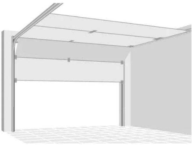
Check of door balance
Make sure, the door is free-moving and well balanced. Lift the door halfway up and release it. If balanced, the door stays in this position only by force of its springs. Call a trained door systems technician, if the door is out of balance or if it binds.
natural_image
3D rendering of a modern metal roof structure with arched windows and grid-patterned floor (no text or symbols)2
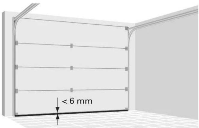
Check of door gap
Make sure, the gap between the closed door and the floor is less than 6 mm. Otherwise the reversal system may not work properly.
3
Rail assembly
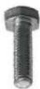
Join the three sections of the rail with the connectors. Make sure that the belt is not distorted. Fix each joint with four nuts and cup square bolts M8x20.
8x
natural_image
Technical diagram of a metal structural assembly with multiple supports and mounting holes (no text or symbols)
CAUTION
To prevent injury from pinching, keep hands away from the joints while assembling the rail.
4
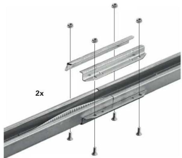
Sprocket assembly
Flip the rail. Centre the bore holes in the sprocket assembly under the appropriate holes in the rail and fi x the sprocket assembly with the two Phillips screws M5x20.
natural_image
Technical illustration of a metal I-beam with screws and screw holes, shown alongside an inset close-up of its internal structure (no text or symbols)5
Motor unit
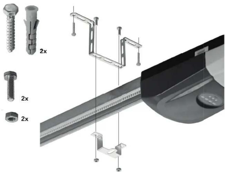
Join the motor unit and the rail. Fit the shaft of the motor unit slips into the sprocket assembly. Position the two U rail clips according to the holes in the motor unit. To fix the clips, use the four self-threading screws M6x16. Other screws might seri- ously damage the garage door opener.
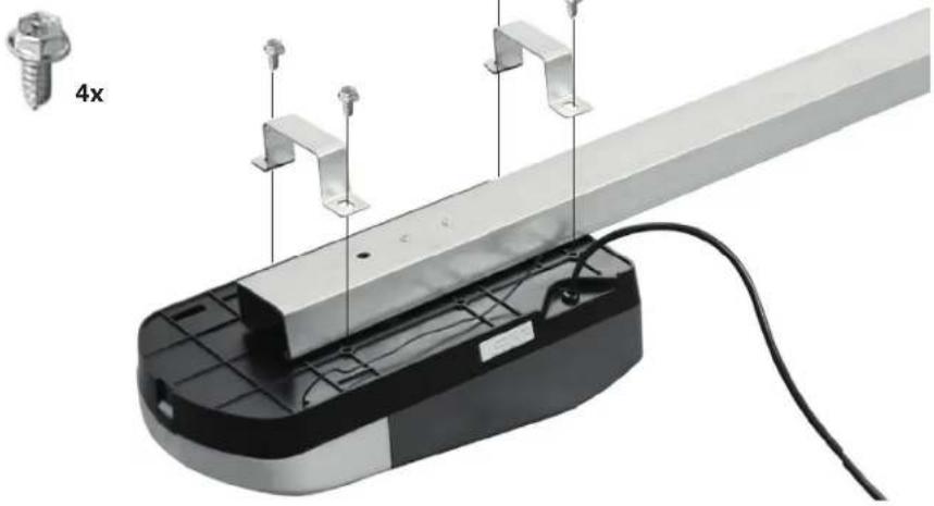
natural_image
Mechanical assembly with metal frame and wiring, no visible text or symbols6
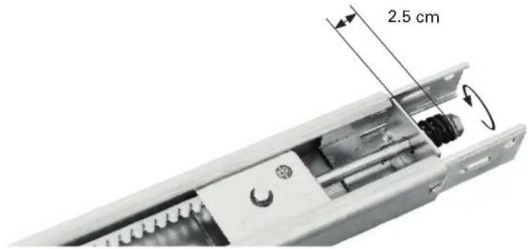
Belt tensioning
Tighten the belt by turning the tension nut clockwise, until the spring is extended to 2.5 cm. Do not overtighten the belt.
7
Header bracket installation
The header bracket should be installed centered over the garage door. If this is not possible, you may fasten the header bracket within 1 m to the right or left of the centre.
The header bracket can be mounted flush against the ceiling when clearance is minimal.

WARNING
To prevent possible serious injury or death:
- Select an installation location without pipes or cables behind it.
- Header bracket must be rigidly fastened to structural support on header wall or ceiling, otherwise garage door might not reverse when required. Do not install header bracket over drywall.
- Concrete anchors must be used if mounting bracket or structural support into masonry.
- Never try to loosen, move or adjust garage door, springs, cables, pulleys, brackets or their hardware, all of which are under extreme tension.
8
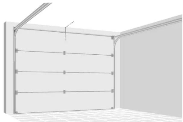
Horizontal positioning
Close the door and mark the inside vertical centerline of the garage door. Extend the line onto the header wall above the door.
For ceiling mount extend line onto the ceiling.
natural_image
3D rendering of a room corner with horizontal shelves and a vertical beam, no text or symbols present9
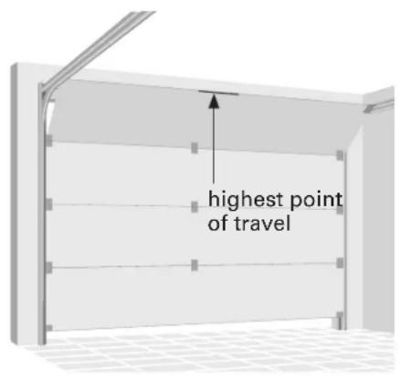
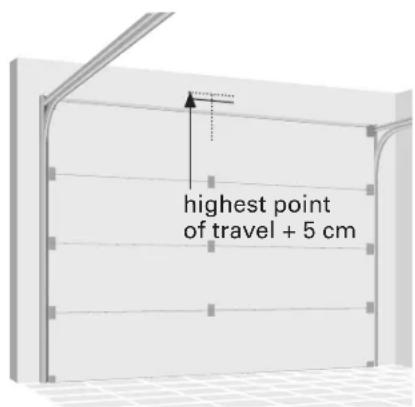
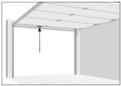
Vertical positioning for wall mount
Open your door to the highest point of travel. Draw a horizontal line onto the header wall at the highest point of travel plus 5 cm.
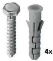
10a
Wall mount
Install the header bracket with its sides pointing upwards. Center the bracket as shown with its bottom edge on the horizontal line.
Mark the fastening holes and drill the holes. Fix the bracket with appropriate plugs and screws.
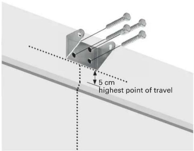
10b
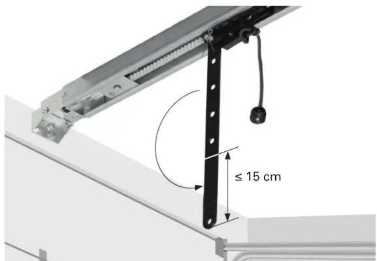
Ceiling mount
Center the header bracket on the mark, no more than 15 cm from the wall.
Mark the fastening holes and drill the holes. Fix the bracket with appropriate plugs and screws.
11
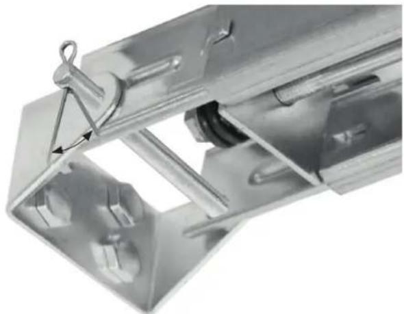
Attach the rail to header bracket
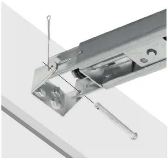
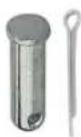
Align the holes in the rail and the bracket and insert the long shouldered shaft.
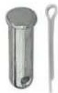
Fix the shaft with a cotter pin.
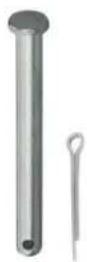
1x
natural_image
Close-up of a metallic mechanical component with internal parts and a tool, no visible text or symbols12
Brace the brackets of the cotter pin to secure it in place.

natural_image
Close-up of a metallic mechanical component with a triangular clip and internal structure (no visible text or symbols)13
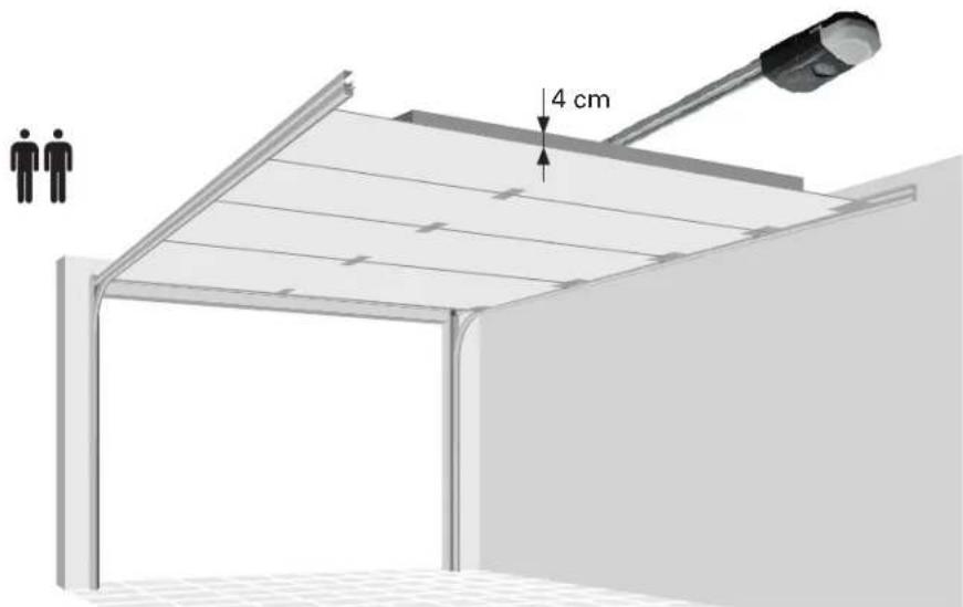
Lift the rail at motor end up to the ceiling. Open the garage door fully. Put a batten (4 cm thick) on the top end of the garage door and lay the rail on it.

14
Hang the garage door opener
Bend the hanging brackets to bridge the distance between the garage door opener and the ceiling.
Mark the fastening holes and drill the holes. Fix the bracket with appropriate plugs and screws.
Attach the rail to the hanging brackets with the U rail.
Remove the batten from the garage door.

WARNING
To prevent possible serious injury or death:
- Select an installation location without pipes or cables behind it.
- Bracket must be rigidly fastened to structural support on ceiling, otherwise garage door might not reverse when required. Do not install bracket over drywall.
- Concrete anchors must be used if mounting bracket or structural support into masonry.
natural_image
Technical illustration of a mechanical assembly with multiple components and a close-up view of a component (no text or symbols present)15
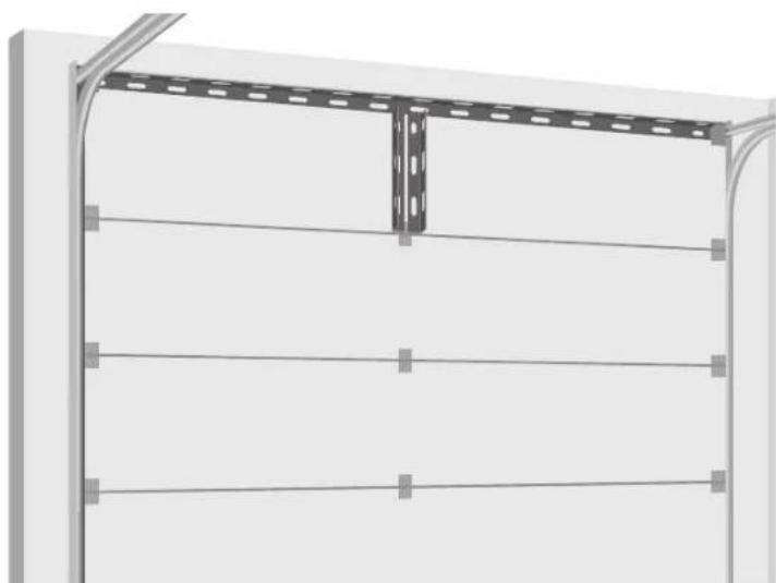
Door reinforcement

CAUTION
Fiberglass, aluminum or lightweight steel garage doors require reinforcement before installation of door bracket.
You might enforce your door with U-shaped braces on your own risk. The horizontal reinforcement should at least be long enough to be secured to two vertical supports. The vertical reinforcement should cover the height of the top panel.
natural_image
Exterior view of a metal shelving unit with horizontal railings and a vertical support bracket (no text or symbols)16a
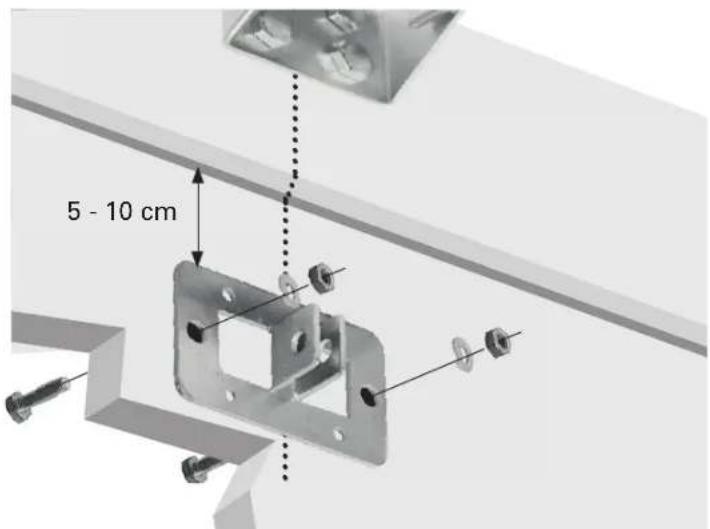
Door bracket mount
Position the top edge of the bracket 5-10 cm below the top edge of the door, or directly below any structural support across the top of the door.
Drill fastening holes and fasten with 4 self-threading screws.
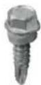
4x
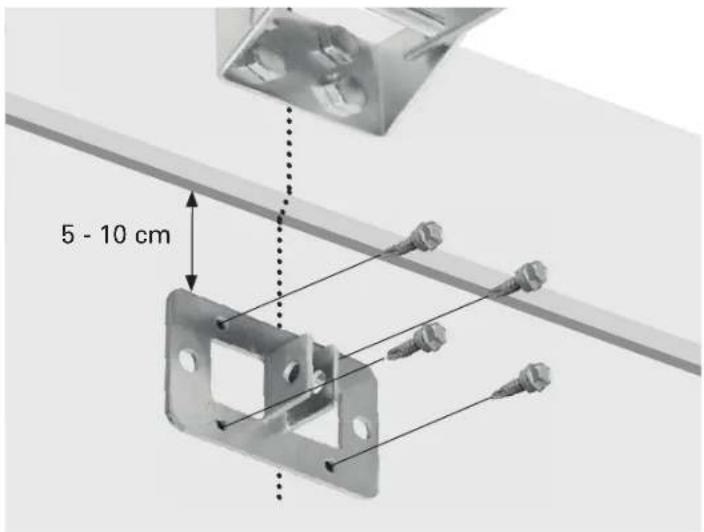
16b
Alternately use machine bolts, lock washers and nuts (not included).
17
Disconnect the trolley by pulling the emergency release handle.
Attach the straight door arm to the trolley with one of the short shouldered shafts.
Fix the shaft with a cotter pin.
Brace the brackets of the cotter pin to secure it in place.
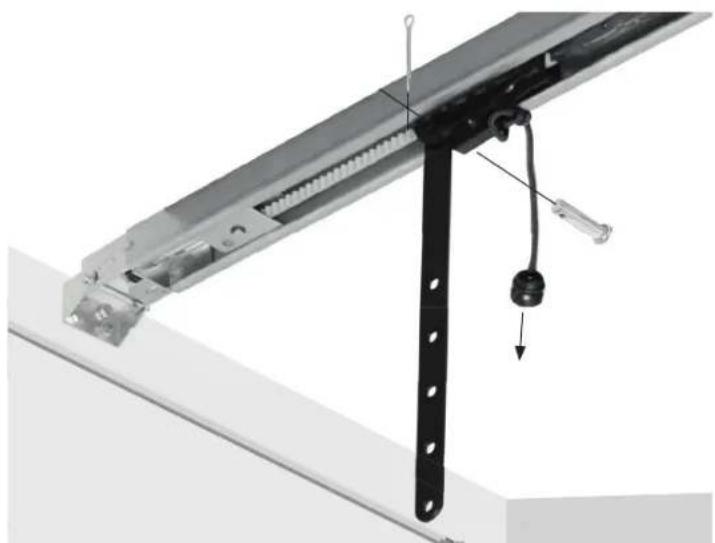
natural_image
Mechanical assembly diagram showing a metal frame with a hanging hook and a downward arrow indicating motion (no text or symbols)18
Attach the curved door arm to the door bracket with the second short shouldered shaft.
Fix the shaft with a cotter pin.
Brace the brackets of the cotter pin to secure it in place.
Join arms with the bolts and nuts. Select holes as far apart as possible to increase door arm rigidity.

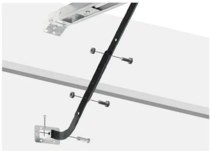
natural_image
Technical diagram of a black metal bracket with mounting screws and a wall-mounted frame (no text or symbols)19
If the holes in the curved door arm and the straight door arm do not align, reverse the straight door arm. Proceed with step 18. If necessary, you may cut up to 15cm from the solid end of the straight arm.
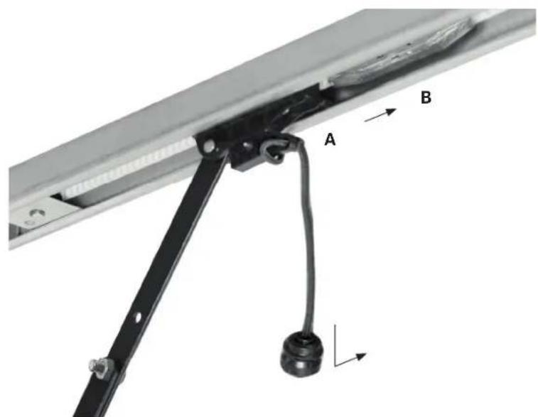
20
Pull the trolley A with the emergency release handle over the belt connector B until they click into place.

CAUTION
If your garage has no second entry, install an emergency door release kit of your garage door supplier to be able to open the door in case of malfunction.
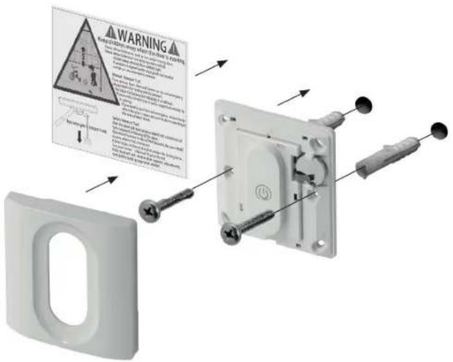
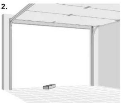
21
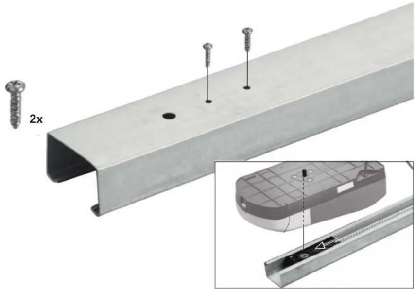
Installing the wall control
Take off the lid. Select an installation location in sight of the garage door without pipes or cables behind it. Mark the fastening holes and drill them. Fix the wall control with the plugs and screws.
Place entrapment warning label on wall next to garage door control.
22
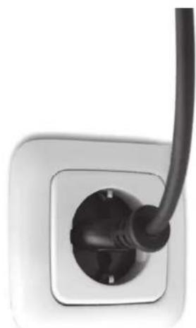
Power connection
Connect garage door opener to a suitable outlet (see technical data). Ensure that the cable is not in the way of the garage door, cars or people.
natural_image
Close-up of a black cable inserted into a white electrical socket (no text or symbols visible)Programming
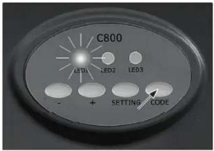
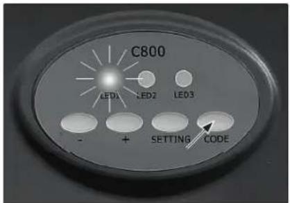
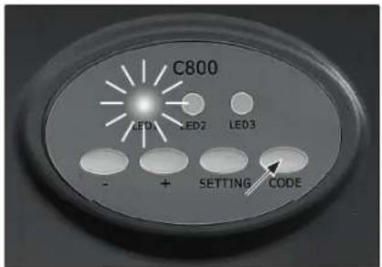
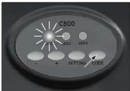
1
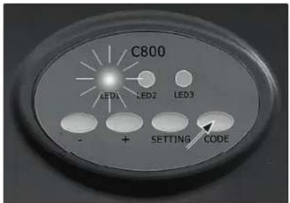
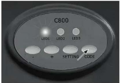
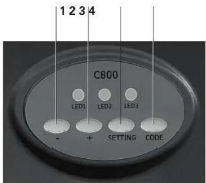
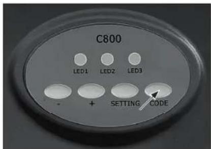
Programming buttons on motor unit:
- (Down button) 1
+(Up button)2
Setting button 3
Code button 4
2
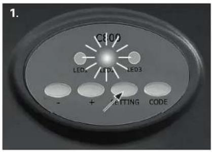
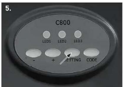
Programming the way of travel
1.
Press and hold setting button until LED 2 shines continuously.
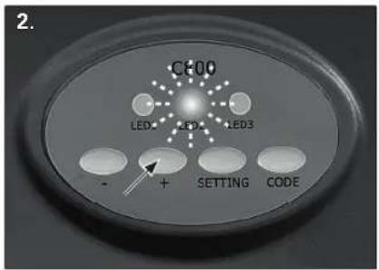
2.
Press and hold + (up button) until door is in desired up position. LED 2 blinks. To prevent damage to vehicles, ensure that the door is fully open.
3.
Once the door is in the desired up position, press and hold setting button, until LED 3 shines continuously.
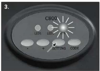
4.
Press and hold – (down button) until door is in the desired down position.
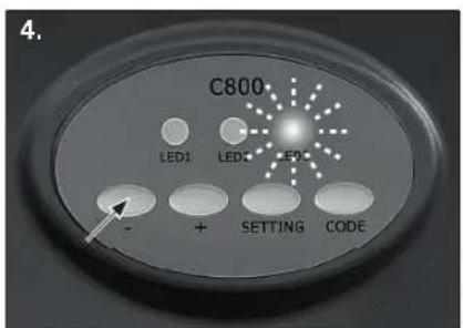
5.
Once the door is in the desired down position, press and hold setting button until LED turns off.
natural_image
Exterior view of a modern building roof with a ceiling-mounted fixture and a hanging fixture (no text or symbols visible)
natural_image
Interior view of a room with ceiling grilles and a wall-mounted panel, showing a downward arrow indicating compression or displacement (no text or symbols)3
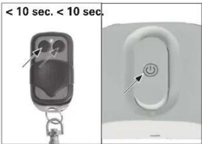
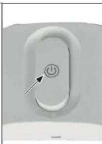
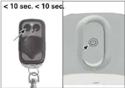
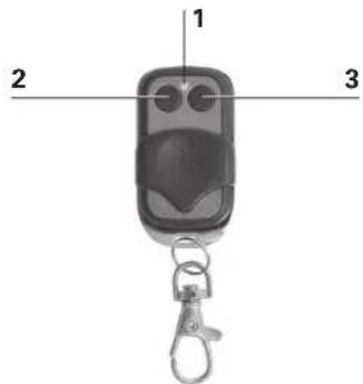
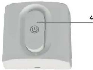
Pairing controls
LED indicator 1
Button 1 2
Button 2 3
Activating button 4
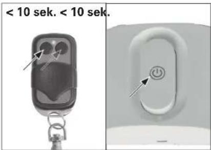
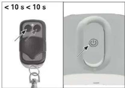
1.
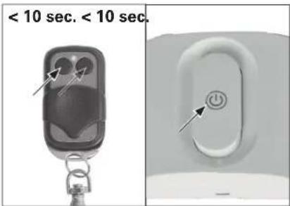
Press the Code button until the LED 1 shines continuously.
2.
Within 10 seconds, press button 1 or 2 of the remote control, or the activating button of the wall control.
3.
Press the same button again. LED 1 will fl ash and turn off. Repeat steps 1. to 3. to code up to a maximum of 10 remote controls.
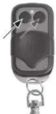
Remote control
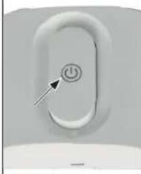
Wall control
natural_image
Close-up of a white electronic device with a button and labeled point '4' (no text or symbols beyond the label)1.
2.
Safety reversal system test

WARNING
Without a properly installed safety reversal system, persons (particularly small children) could be seriously injured or even killed by a closing garage door. Incorrect adjustment of garage door travel limits will interfere with the proper operation of the safety reversal system.
- The safety reversal system MUST be tested at least once every month.
- The safety reversal system must be tested after any adjustments made.
1.
With the door fully open, place a board with a thickness of 5 cm centered in the way of the door.
2.
Press remote control push button. When closing, the door MUST reverse when making contact with the board.
Otherwise do not use the garage door opener any more; instead seek professional assistance for repair.
1.2.
natural_image
Exterior view of a modern office building (no signage)
natural_image
3D diagram of a U-shaped pipe or channel inside a rectangular chamber, with no visible text or symbolsOperation

WARNING
Read and follow all warnings and instructions.
Always keep remote controls out of the reach of children.
Only activate the garage door when you clearly see that there are no obstructions in the way of travel.
Always keep the garage door in sight until completely closed. Ensure that nobody crosses the path of the moving door.
Ensure that nobody goes under a stopped, partially opened door.
If possible, use emergency release handle only when garage door is closed.
If you need to pull the red emergency release knob when the door is open, be sure no one is standing in the way of door travel.
Weak or broken springs or an unbalanced door could result in an open door falling rapidly and unexpectedly.
Never use emergency release handle to pull the garage door open or closed. If rope knot becomes untied, you could fall.
Due to remote control the door may move unexpectedly. Ensure that nobody crosses the path of the moving door.
- Press button on wall control or remote control to start the garage door opener. The door will always move in the opposite direction of the last run.
- Door stops if fully open or closed.
· Alternatively, you can stop the movement by pressing the button on the control again. - The door will move in the opposite direction when started again.
Maintenance

WARNING
Always disconnect electric power to garage door opener before making any repairs or removing covers.
All repairs to cables, spring assemblies and other hardware must be made by a trained door systems technician.

WARNING
Regularly execute the manual release test and the safety reverse test. Maintain the garage door as advised in the door manual. Lack of maintenance can lead to unsafe operation.
- Make sure, that the warning label is fixed properly and fully legible.
Maintenance work by operator
- Damage or wear to a door system must only be rectified by qualified and trained professionals.
- To ensure fault –free operation, the door system must be inspected regularly and, if necessary, repaired. Always disconnect operating system from the power supply before starting work on the door system.
- Regularly check that the safety devices function correctly; no less than every six months.
- Do the safety reversal test once a month (see "Safety reversal system test").
- Check all the moving parts of the door system and door operator system.
- Check the door system for signs of damage or wear and tear.
- Move the door manually to check that the door travels easily and smoothly.
- Check all power supply cables for signs of damage.
Monthly maintenance
Manual release test

WARNING
An unbalanced door may fall down when released. Keep doorway free during test.
- Close garage door, then pull down the red emergency release handle. The trolley will disconnect.
- Test door for balance by releasing it at halfway. If balanced, it should stay in place, supported entirely by its springs. If the door falls down, seek professional garage door service.
Safety reversal test
- With the door full open, place a board with a thickness of 5 cm centered in the way of the door.
- The closing door must reverse when it hits the board. If door stops on the obstruction, seek professional garage door service.
Cleaning
- If the garage door opener or the controls need cleaning, wipe them with a brush or a soft damp cloth. A mild detergent can be used but nothing like alcohol, petrol or other cleaning agent.
- Never use caustic agents to clean plastic parts.
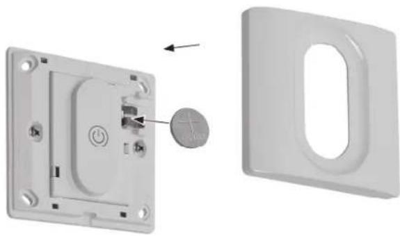
Battery change of wall control
Remove cover inserting a small screwdriver into the slot at the bottom of the lid.
Insert a new C2032 battery (+ side outwards) and reinstall the lid.
natural_image
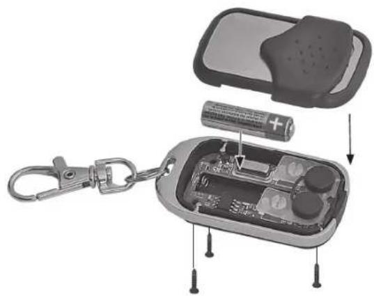
3D diagram showing a switch inside a wall-mounted device and its external casing (no text or symbols)Battery change of remote control
Unscrew the three little screws at the backside of the remote control, take of the lid and insert a new L828 battery. Please observe the polarity. Reinstall the lid.
natural_image
Exploded view of a smart lock-in case showing battery, switch, and internal components (no text or symbols visible)Erasing controls
-
Press and hold the Code button, the LED 1 turns on.
-
Release the button when LED 1 turns off. All remote controls are now erased. This might become necessary if a remote control gets lost. 3.
To pair controls again, see chapter "Programming" section 3).
1.2.
Troubleshooting
PROBLEM CAUSE SOLUTION
| Garage door doesn’t open | Door locked | Remove all locks before operating the garage door opener |
| Control not connected (try another control to confirm) | Move remote control closer to the garage door openerReplace battery (see section “Battery change”)Pair control (see section “Programming”)Replace control | |
| Door sticks (after pulling the emergency release, the door may be moved only with excessive force) | Have a trained door systems technician maintain the door. | |
| Power connection failure Plug garage door opener plug into a suitable live socketCheck the socket with a suitable luminaireHave a qualified electrician repair the power connection, if socket is not live | ||
| Garage door doesn’t close/open fully | Brackets, connections, arms impaired | Check garage door and door opener; re-programme the way of travel; always test safety reversal system after programming |
| Door not balanced (after pulling the emergency release and opening the door half-way, the door isn’t held in that position by its springs) | Have a trained door systems technician maintain the door. | |
| Garage door reverses during closing | Door sticks (after pulling the emergency release, the door may be moved only with excessive force) | Have a trained door systems technician maintain the door. |
| Obstacles in the way Remove obstacles | like stones and ice in the doorway | |
| Way of travel set improperly Re-programme the way of travel; always test safety reversal system after programming | ||
Disposal

The pictogram with the crossed out dustbin points to the requirement for separate disposal of electrical and electronic appliances (WEEE).
Electrical and electronic appliances can contain
hazardous and environmentally hazardous materials. Do not dispose of this appliance as domestic waste. Hand it in at a collection point for electrical and electronic waste. By doing so, you will help to conserve resources and protect the environment. For further details, please consult your dealer or your local authorities.
Used batteries must be disposed of properly. Battery selling stores and municipal collection points offer special containers for battery disposal.
Children must not play with plastic bags and packaging material, due to possible injury or danger of suffocation. Store such material safely or dispose of environmentally friendly