
IAN 368781 - Bike accessory CRIVIT - Free user manual and instructions
Find the device manual for free IAN 368781 CRIVIT in PDF.

| Product type | Bike work stand (repair stand) |
| Brand | Crivit |
| Model | IAN 368781 |
| Maximum load capacity | 30 kg (25 kg if attached to seat post or if center of gravity is altered) |
| Compatible frame diameter | Approximately 25 mm to 55 mm |
| Main material | Steel (assumed) |
| Adjustable height | Yes, via telescopic tube |
| Adjustable support angle | Yes, via locking lever |
| Front wheel stabilizer | Included with rubber connectors |
| Tool tray | Included, with magnet for small parts |
| Floor anchoring | Possible via ballast or screwing (not supplied) |
| Product weight | Not specified (estimated: about 5 kg) |
| Intended use | Private, for bicycle repairs and maintenance |
| Cleaning | Water only, no harsh detergents |
| Storage | In a dry and clean place at room temperature |
| Warranty | 3 years (material and manufacturing defects) |
| After-sales service France | Tel: 0800 919270, Email: deltasport@lidl.fr |
| Delivery contents | Tripod, bike mount, telescopic tube, stabilizer, rubber connectors, tool tray, brackets, screws, Allen key, manual |
| Safety | Do not exceed 30 kg, flat and stable surface, do not sit on the bike, be careful with carbon frames |
Frequently Asked Questions - IAN 368781 CRIVIT
User questions about IAN 368781 CRIVIT
0 question about this device. Answer the ones you know or ask your own.
Ask a new question about this device
Download the instructions for your Bike accessory in PDF format for free! Find your manual IAN 368781 - CRIVIT and take your electronic device back in hand. On this page are published all the documents necessary for the use of your device. IAN 368781 by CRIVIT.
USER MANUAL IAN 368781 CRIVIT
Instructions for use
NL EG
FIETS-MONTAGESTEUN
Gebruiksaanwijzing
CZ
MONTÁŽNÍ STOJAN NA KOLO
Návod k použiti
IS
SOPORTE DE TALLER PARA BICICLETAS
Before reading, fold out the illustration page and get to know all of the functions of your unit.
图图
GS/IE Usage and safety information Page 11
| FR/BE Consignes d'utilisation en da vortuń | Page | 15 | |
| N/BE | Gebruks en veiligheidships | Pages 20 | |
| FL | Winkzetki elat uzykrowszeni bezpieczanlava | Strona | 24 |
| CZ | Pokyny i podziti a bezpandrot | Shórsky | 28 |
| SK | Pokyny pre použivanie a bezpečnost | Strona | 32 |
| LS | Inn accima de nu y seguridad | Pages | 36 |
| DK | Brugy og sikkerhadsorvninger | Side | 40 |
IAN 384433_2107IAN 384433_2107
natural_image
Illustration of a bicycle mounted on a pole with labeled components (no text or symbols beyond 'D' and number '2')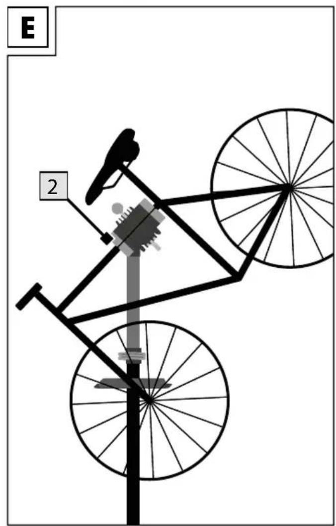
natural_image
Two identical diagrams showing a tree with a checkmark and an X mark, no text or symbols present.You have chosen to purchase a high-quality product. Familiarise yourself with the product before using it for the first time.

Read the following instructions for use carefully.
Use the product only as described and only for the given areas of application. Store these instructions for use carefully. When passing the product on to third parties, please also hand over all accompanying documents.
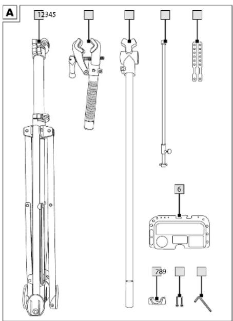
Scope of delivery (fig. A)
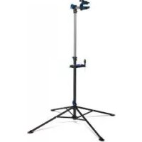
1 x stand with support feet (1)
1 x bicycle mount (2)
1 x telescopic rod (3)
1 x front wheel stabiliser (4)
2 x rubber connection (5)
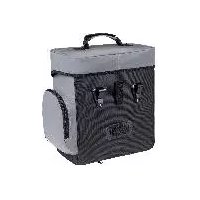
1 x tool tray (6)
1 x clamp (7)
2 x screw (8)
1 x allen key (9)
1 x instructions for use
1 x quick start guide
Technical data
Maximum load capacity: 30kg
For bicycle frames: ∅ of approx. 25mm - 55mm
natural_image
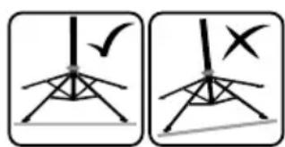
Two identical diagrams showing a vertical pole with a checkmark and an X-shaped symbol, no text or labels present.Ensure that the floor is level and position is stable.

Date of manufacture (month/year): 12/2021
Intended use
This bicycle repair stand has been developed for private use. It allows bicycles to be suspended and clamped so that repairs can be performed.

Safety instructions
Risk of injury!
- Read through the instructions for use before assembly and follow the steps one by one as described in the instructions.
- WARNING! Do not exceed the maximum load capacity of 30kg!
- There is risk of injury and of damage to the product.
- Check all parts of the product regularly. Loose screws must be tightened and defective parts replaced in order to avoid damage to the product.
- Make sure that the socket screws on the upper tube connector always remain tight.
- WARNING! Set the product up only on a firm and even surface to prevent the product from falling over.
- WARNING! No one must sit on the bicycle once clamped. There is risk of injury
- WARNING! Any use other than for the intended purpose or any improper use can lead to endangerment of persons or damage to the bicycle.
- Avoid any aggressive chemical substances (e.g. solvents)!
- Discontinue use if damaged.
- When using the product always adhere to the operating instructions of the pedelec or bicycle manufacturer.
- Check the product for damage and wear before each use. The product may only be used in good order and condition!
Caution! Risk of trapping fingers!
- When unfolding and folding up the repair stand be sure not to trap your fingers.
- Position the repair stand so that you have enough space for movement, including when the bicycle is set up.
Avoiding material damage!
- To prevent damage to the bicycle be careful not to trap any parts or cabling in the repair stand.
-
Carbon frames and other bicycle frames with thin walls are extremely sensitive to pressure! Use appropriate clamping force of the clamp so as not to damage the frame.
-
Guiding and locking parts must be kept free of oil and grease.
- Not all types of frames and cross-sections can be clamped in the product.
Assembly
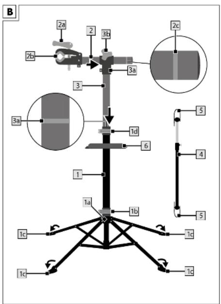
- Spread out the legs of the stand (1) a little and place it on the ground (fig. B).
- Slide the joint connection (1a) down as far as the stop (fig. B).
- Open the quick release clamp (1b) on the joint connection (fig. B).
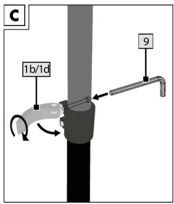
- To set in position, insert the Allen key (9) into the end of the quick release clamp, as shown in fig. C, and turn it clockwise until you feel a slight resistance.
- Give it one more turn and then close the quick release clamp. When you close it you should feel stiff resistance.
- Check that it is set up properly.
- Fold down the feet (1c) on the legs of the stand and make sure that the product is standing on a firm and stable surface (fig. B).
- Insert the telescopic rod (3) up into the stand.
- Insert the bicycle mount (2) through the bracket (3a) of the telescopic rod (fig. B).
Note: Observe the maximum extension length of the bicycle mount (2) and do not exceed the markings indicated (2c).
-
Turn the fixing screw (3b) until the bicycle mount sits securely in the bracket of the telescopic rod (fig. B).
-
Position the bracket (7) anywhere on the stand (1) and opposite the tool tray (6).
-
Insert the screws (8) into the holes in the bracket and screw them in with the aid of the Allen key to attach the tool tray to the stand.
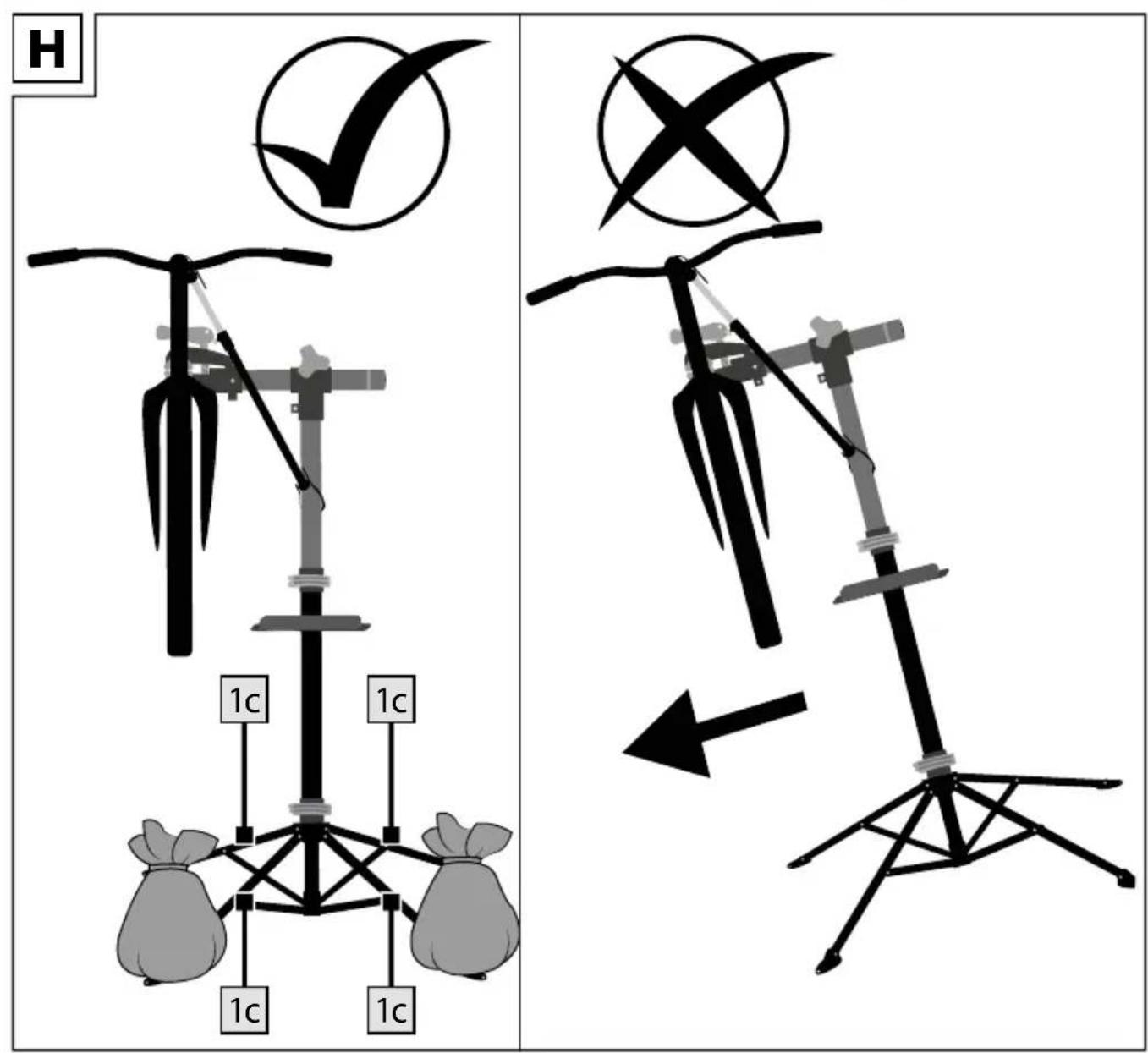
Note: If there is a risk of the bike repair stand tipping over when being used, weigh down all four legs (1c) (fig. H). Make sure that the ballast cannot shift unintentionally. Place the ballast on the legs (1c) uniformly and covering a broad surface area. As an option you can screw the feet of the repair stand to the floor in accordance with professional standards to increase the positional stability. When doing so use appropriate assembly materials. Ask your specialist retailer what materials (screws and dowels) are appropriate.
Mounting the bicycle
! Tips:
• After mounting the bicycle check that both the bicycle and the bicycle repair stand are securely in position.
- Stay within the maximum extension lengths of the telescopic rod (3) and the bicycle mount (2) without exceeding the markings indicated (2c)/(3a) (fig. B).
- If you attach the bicycle to a vertical frame post (e.g. seat post) the maximum load capacity decreases to 25kg.
- Be sure to attach the bicycle at its centre of gravity. Otherwise there is the risk that the bicycle may turn.
- If the centre of gravity at the point of attachment shifts while you are working on the bicycle, you must readjust the bicycle in the mount so that the centre of gravity is restored.
If not, the maximum load capacity decreases to 25kg.
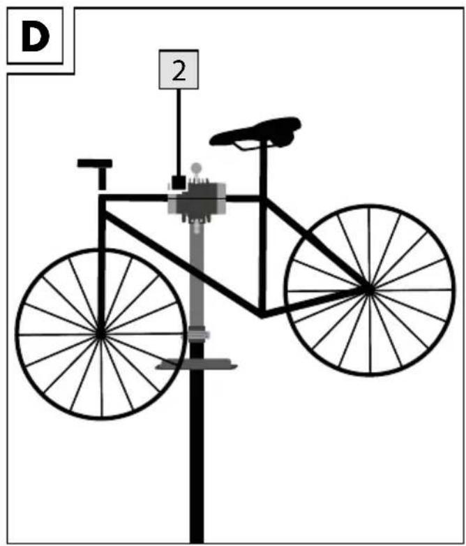
- Choose a section of the bicycle frame that you want to clamp in the repair stand mount (2).
Note: This section of the frame must always be located in the bicycle's centre of gravity.
-
Set the angle of the bicycle mount (2) to match the selected position of the bicycle frame (see examples in figs. D and E).
-
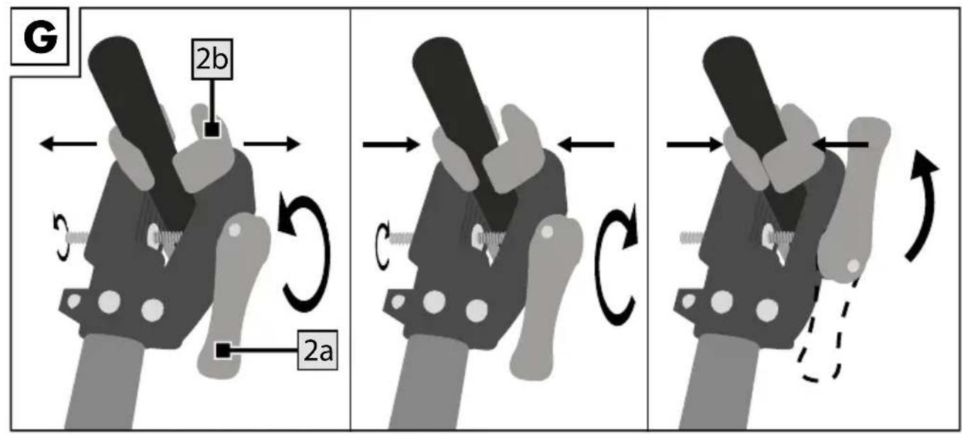
Flip the quick release lever (2a) to open the clamp (2b) (fig. G).
-
Place the bicycle frame in the clamp and flip the quick release lever back again to close the clamp.
Note: Make sure that the clamping force is sufficient.
Setting the clamping force
If the quick release lever (2a) can be flipped too easily, the clamping force is insufficient.
- Turn the quick release lever in a clockwise direction to increase the clamping force (fig. G).
Note: If the quick release lever cannot be flipped, the clamping force is too great.
- Reduce the clamping force by turning the quick release lever counter-clockwise.
- Loosen the clamp one half turn and then try to close the quick release lever.
- Repeat this procedure until you find the maximum clamping force at which the quick release lever can still be flipped.
Adjusting the telescopic rod
You can set the telescopic rod at any desired height.
We recommend that 2 people perform the next step (height adjustment).
- Turn the telescopic rod (3) to change the position of the bicycle when clamped.
- Open the quick release clamp (1d) on the stand.
- Set the telescopic rod at the desired height.
Note: Observe the maximum extension length of the telescopic rod (3) and do not exceed the indicated markings (3a).
- As shown in fig. C, to fix in position insert the Allen key (9) into the end of the quick release clamp (1b)/(1d) and turn it clockwise until you feel a slight resistance.
- Give it one more turn and then flip the quick release clamp. When you flip it you should feel stiff resistance.
- Check the fixation.
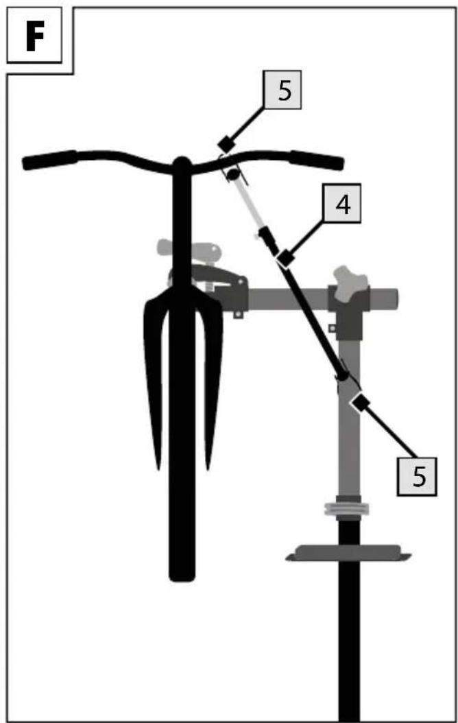
Stabilising the front wheel
Attach the rubber connections (5) on the ends of the front wheel stabiliser (4). Using the front wheel stabiliser fix the front wheel in position between the handlebars and the telescopic tube (fig. F).
Tool tray
A magnet is located inside the large compartment of the tool tray for securing small parts.
Maintenance
Ensure that the hexagonal screws on the upper tube connector are always tightly secured as well. Check all parts of the bike work stand regularly. Loose screw connections must be tightened and defective parts replaced to avoid damage to the product.
Storage, cleaning
When not in use, always store the product clean and dry at room temperature.
Clean only with water and wipe dry afterwards with a cloth.
IMPORTANT! Never clean the product with harsh cleaning agents.
Disposal
Dispose of the article and the packaging materials in accordance with current local regulations. Packaging materials such as foil bags are not suitable to be given to children. Keep the packaging materials out of the reach of children.

Dispose of the products and the packaging in an environmentally friendly manner.

The recycling code is used to identify various materials for recycling. The code consists of the recycling symbol - which is meant to reflect the recycling cycle – and a number which identifies the material.
Notes on the guarantee and service handling
The product was produced with great care and under continuous quality control. DELTA-SPORT HANDELSKONTOR GmbH gives private end customers a three-year guarantee on this product from the date of purchase (guarantee period) in accordance with the following provisions. The guarantee is only valid for material and manufacturing defects. The guarantee does not cover parts subject to normal wear and tear that are thus considered wear parts (e.g. batteries) or fragile parts such as switches, rechargeable batteries, or parts made of glass.
Claims under this guarantee are excluded if the product has been used incorrectly, improperly, or contrary to the intended purpose, or if the provisions in the instructions for use were not observed, unless the end customer proves that a material or manufacturing defect exists that was not caused by one of the aforementioned circumstances.
Claims under the guarantee can only be made within the guarantee period by presenting the original sales receipt. Please therefore keep the original sales receipt. The guarantee period is not extended by any repairs carried out under the guarantee, under statutory guarantees, or as a gesture of goodwill. This also applies to replaced and repaired parts.
If you wish to make a claim please first contact the service hotline mentioned below or contact us by e-mail. If there is a guarantee case, then the product will be repaired or replaced free of charge to you or the purchase price will be refunded, depending on our choice.
Your legal rights, in particular guarantee claims against the respective seller, are not limited by this guarantee.
IAN: 384433_2107
GB Service Great Britain
Tel.: 0800 404 7657
E-Mail: deltasport@lidl.co.uk
IE Service Ireland
Tel.: 1890 930 034
(0,08 EUR/Min., (peak))
(0,06 EUR/Min., (off peak))
E-Mail: deltasport@lidl.ie
Félicitations!
natural_image
Two identical diagrams showing a tree with a checkmark and an X mark, no text or symbols present.natural_image
Two identical diagrams showing a vertical pole with a checkmark and an X-shaped symbol, no text or labels present.natural_image
Two identical diagrams showing a tree with a checkmark and an X mark, no text or symbols present.natural_image
Two identical diagrams showing a tripod with a checkmark and an X mark, no text or symbols present.


- Read the following instructions for use carefully.
- Scope of delivery (fig. A)
- Technical data
- Intended use
- Safety instructions
- Risk of injury!
- Caution! Risk of trapping fingers!
- Avoiding material damage!
- Assembly
- Mounting the bicycle
- ! Tips:
- Setting the clamping force
- Adjusting the telescopic rod
- We recommend that 2 people perform the next step (height adjustment).
- Stabilising the front wheel
- Tool tray
- Maintenance
- Storage, cleaning
- Disposal
- Notes on the guarantee and service handling
Brand : CRIVIT
Model : IAN 368781
Category : Bike accessory