
IAN 292230 - Bike accessory CRIVIT - Free user manual and instructions
Find the device manual for free IAN 292230 CRIVIT in PDF.
| Product Type | Bicycle Workstand |
| Brand | Crivit |
| Model | IAN 292230 |
| Maximum Load | 30 kg (25 kg if fixed on vertical frame bar) |
| Compatible Frame Diameter | 2.5 cm - 5.5 cm |
| Adjustable Height | Yes, via telescopic bar |
| Main Material | Steel and aluminum |
| Color | Black (estimated) |
| Weight | Approx. 5 kg (estimated) |
| Package Contents | 1 workstand, 1 mounting tool, 1 front wheel stabilizer, 1 tool tray, instruction manual |
| Main Functions | Support for bicycle repair, assembly and maintenance |
| Tool Tray | Magnet for fixing small parts |
| Front Wheel Stabilizer | Included to stabilize the front wheel while working |
| Care and Cleaning | Clean with warm water and neutral soap, dry with a dry cloth |
| Safety | Do not exceed 30 kg, use on level surface, do not stand on the bike, risk of crushing during folding |
| Warranty | 3 years from date of purchase |
| After-sales service (Belgium) | Tel.: 070 270 171 (€0.15/min), Email: deltasport@lidl.be |
| Intended Use | Private, domestic use |
| Storage | Dry and well-ventilated place |
| Spare Parts | Available during the warranty period |
Frequently Asked Questions - IAN 292230 CRIVIT
User questions about IAN 292230 CRIVIT
0 question about this device. Answer the ones you know or ask your own.
Ask a new question about this device
Download the instructions for your Bike accessory in PDF format for free! Find your manual IAN 292230 - CRIVIT and take your electronic device back in hand. On this page are published all the documents necessary for the use of your device. IAN 292230 by CRIVIT.
USER MANUAL IAN 292230 CRIVIT
natural_image
Black tripod-mounted stand with a tripod base, no visible text or symbols on the device or background.BIKE WORKSTAND
DELTA SPORT HANDELSKONITOR GMBH
- 100%
0522197 Harburg
CERIKAVIN
(1) 本次股东大会的决议有效期

12/2017
2016.04.03
(2) (2)
OE ME NI
BIKE WORKSTAND
Instructions for use
FR 26
PIED D'ATELIER POUR VÉLO
Mode d'emploi
DE AT CH
(2) 30 (45)
Before reading, told out the illustration page and got to know all of the functions of your crit.
[Illegible]
GS/IE/NI Instructions and Safety Notice Page 6
DK Betenings op sikserbedshervisninger Side 9
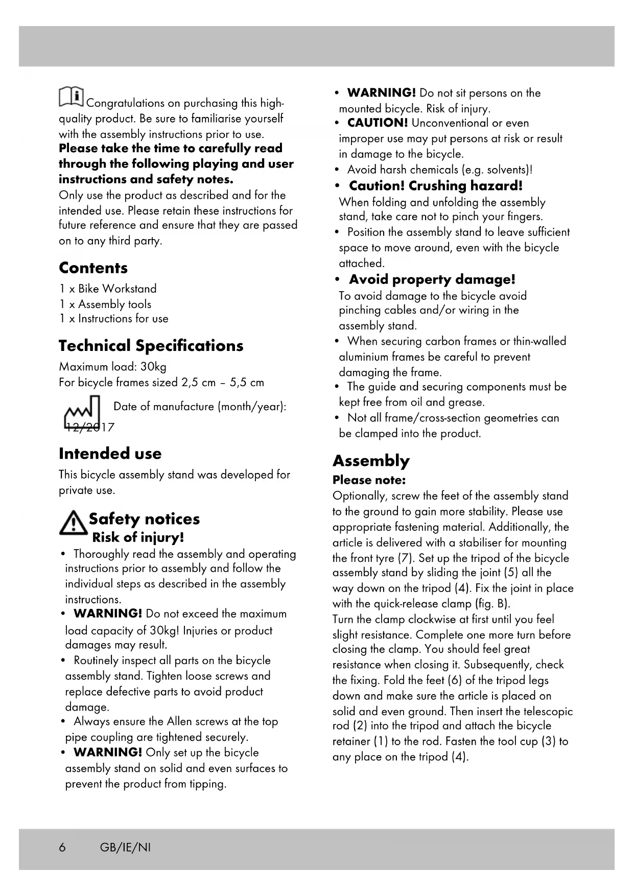
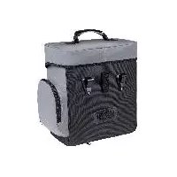
GB Overview of parts:

(1) Bicycle bracket
(2) Telescopic pole
(3) Tool tray
(4) Tripod
(5) Joint
(6) Feet
(7) Front wheel stabiliser
DK Deloversigt:
Congratulations on purchasing this high-quality product. Be sure to familiarise yourself with the assembly instructions prior to use. Please take the time to carefully read through the following playing and user instructions and safety notes.
Only use the product as described and for the intended use. Please retain these instructions for future reference and ensure that they are passed on to any third party.
Contents
1 x Bike Workstand
1 x Assembly tools
1 x Instructions for use
Technical Specifications
Maximum load: 30kg
For bicycle frames sized 2,5 cm - 5,5 cm

Date of manufacture (month/year):
Intended use
This bicycle assembly stand was developed for private use.

Safety notices
Risk of injury!
- Thoroughly read the assembly and operating instructions prior to assembly and follow the individual steps as described in the assembly instructions.
- WARNING! Do not exceed the maximum load capacity of 30kg! Injuries or product damages may result.
- Routinely inspect all parts on the bicycle assembly stand. Tighten loose screws and replace defective parts to avoid product damage.
• Always ensure the Allen screws at the top pipe coupling are tightened securely. -
WARNING! Only set up the bicycle assembly stand on solid and even surfaces to prevent the product from tipping.
-
WARNING! Do not sit persons on the mounted bicycle. Risk of injury.
- CAUTION! Unconventional or even improper use may put persons at risk or result in damage to the bicycle.
- Avoid harsh chemicals (e.g. solvents)!
• Caution! Crushing hazard!
When folding and unfolding the assembly stand, take care not to pinch your fingers.
- Position the assembly stand to leave sufficient space to move around, even with the bicycle attached.
- Avoid property damage!
To avoid damage to the bicycle avoid pinching cables and/or wiring in the assembly stand.
- When securing carbon frames or thin-walled aluminium frames be careful to prevent damaging the frame.
- The guide and securing components must be kept free from oil and grease.
- Not all frame/cross-section geometries can be clamped into the product.
Assembly
Please note:
Optionally, screw the feet of the assembly stand to the ground to gain more stability. Please use appropriate fastening material. Additionally, the article is delivered with a stabiliser for mounting the front tyre (7). Set up the tripod of the bicycle assembly stand by sliding the joint (5) all the way down on the tripod (4). Fix the joint in place with the quick-release clamp (fig. B).
Turn the clamp clockwise at first until you feel slight resistance. Complete one more turn before closing the clamp. You should feel great resistance when closing it. Subsequently, check the fixing. Fold the feet (6) of the tripod legs down and make sure the article is placed on solid and even ground. Then insert the telescopic rod (2) into the tripod and attach the bicycle retainer (1) to the rod. Fasten the tool cup (3) to any place on the tripod (4).
Attaching the bicycle

Instructions:
• After positioning, make sure that the bicycle fits safely and that the assembly stand is stable.
- Please observe the maximum extension lengths of the telescopic rod (2) and the bicycle retainer (1); do not exceed the marking.
- If you attach the bicycle by a vertical frame tube (e.g. the seat tube), then the maximum load capacity is reduced to 25 kg.
- Please ensure that the bicycle is attached at the centre of mass. Otherwise there is a risk that the bicycle will turn.
- If the centre of mass of the attached bicycle changes during work, then you need to readjust the bicycle in the cycle bracket so that the bicycle is attached at its centre of mass again. Otherwise the maximum load capacity is reduced to 25 kg.
Choose the section of the bicycle frame you wish to clamp in the retainer of the bicycle assembly stand. This section of the frame must be located in the bicycle's centre by all means. Set the angle of the bicycle retainer (1) to fit the selected bicycle frame length (see examples in fig. C and fig. D) and tighten the screw on the clamping device of the retainer.
Turn the quick release lever anti-clockwise to open the clamping device (Fig. F).
Put the bicycle frame into the clamping device and turn the quick release lever in a clockwise direction until the quick release lever can be moved around with force (Fig. F).
Make sure to have an adequate clamping force.
Note: If the quick release lever can be moved around too easily, the clamping force is insufficient. In this case, push the quick release lever back into the open position and turn it in a clockwise direction again to increase the fixed clamping force. Close the quick release again. If the quick release lever cannot be moved around, the clamping force is too strong.
Reduce the clamping force by turning the lever anti-clockwise. Loosen the clamping device by half a turn and then try to close the quick release. Repeat this procedure until you find the maximum clamping force at which the lever can still be moved around.
• We recommend carrying out the following step (height adjustment) with 2 people.
Extend the telescopic rod (2) to the desired height. By turning the rod you can also change the position of the clamped bicycle. As soon as you have reached the desired height and position, fasten the telescopic rod to the tripod with the quick release. Proceed in the same way as with the quick release on the tripod joint (fig. B). To stabilise the front tyre, clamp the front tyre stabiliser (7), that is included in the delivery, between the handlebar and the telescopic rod (fig. E).
Tool tray
A magnet is located inside the large compartment of the tool tray for securing small parts.
Care, storage
Routinely clean the bicycle assembly stand with warm water and pH-neutral soap. Always follow with a dry cloth! Avoid harsh chemicals (e.g. solvents)! Store the product in a dry and well-ventilated area.
Disposal
Dispose of the article and the packaging materials in accordance with current local regulations. Packaging materials such as foil bags are not suitable to be given to children. Keep the packaging materials out of the reach of children.

Devices that are marked with the symbol shown here may not be disposed of with domestic waste.
You are obliged to dispose of these kinds of used electrical and electronic devices separately. Ask your local authority about possible methods for regulated disposal.
Notes on the guarantee and service handling
The product was produced with great care and under constant supervision. You receive a three-year warranty for this product from the date of purchase. Please retain your receipt.
The warranty applies only to material and workmanship and does not apply to misuse or improper handling. Your statutory rights, especially the warranty rights, are not affected by this warranty.
With regard to complaints, please contact the following service hotline or contact us by e-mail. Our service employees will advise as to the subsequent procedure as quickly as possible. We will be personally available to discuss the situation with you. Any repairs under the warranty, statutory guarantees or through goodwill do not extend the warranty period. This also applies to replaced and repaired parts.
Repairs after the warranty are subject to a charge.
IAN: 292230

Service Great Britain
Tel.: 0871 5000 720
(£ 0.10/Min.)
E-Mail: deltasport@lidl.co.uk

Service Ireland

Tel.: 1890 930 034
(0,08 EUR/Min., (peak))
(0,06 EUR/Min., (off peak))
E-Mail: deltasport@lidl.ie

Tillykke!


- BIKE WORKSTAND
- GB Overview of parts:
- DK Deloversigt:
- Contents
- Technical Specifications
- Intended use
- Safety notices
- Risk of injury!
- Assembly
- Please note:
- Attaching the bicycle
- Instructions:
- • We recommend carrying out the following step (height adjustment) with 2 people.
- Tool tray
- Care, storage
- Disposal
- Notes on the guarantee and service handling
- Tillykke!
Brand : CRIVIT
Model : IAN 292230
Category : Bike accessory