IAN 329949 - Ceiling fan Livarno Lux - Free user manual and instructions
Find the device manual for free IAN 329949 Livarno Lux in PDF.

| Product type | Ceiling fan with LED lighting |
| Brand | Livarno Lux |
| Model | IAN 329949 |
| Use | Indoor, dry and enclosed rooms |
| Power supply | 220-240 V~ 50 Hz |
| Total fan power | 50 W |
| Included LED bulb power | 6 W |
| Max bulb power | 60 W |
| Standby consumption | 0.31 W |
| Adjustable speeds | 3 levels (LOW, MED, HI) |
| Maximum speed | 230 rpm |
| Noise level | 52 dB(A) |
| Fan diameter | 107 cm |
| Housing height | 36 cm |
| Protection class | I |
| Protection rating | IP20 |
| Bulb type | E27 (max 60 W) |
| Remote control batteries | 2 x 1.5 V AAA |
| Max ceiling slope | 14° |
| Minimum floor-blade distance | 2.3 m |
| Minimum wall-blade distance | 0.6 m |
| Minimum room height | 2.55 m |
| Functions | Remote control, reversible rotation direction (winter/summer) |
| Blade material | Wood and white (double-sided) |
| Warranty | 3 years |
Frequently Asked Questions - IAN 329949 Livarno Lux
User questions about IAN 329949 Livarno Lux
0 question about this device. Answer the ones you know or ask your own.
Ask a new question about this device
Download the instructions for your Ceiling fan in PDF format for free! Find your manual IAN 329949 - Livarno Lux and take your electronic device back in hand. On this page are published all the documents necessary for the use of your device. IAN 329949 by Livarno Lux.
USER MANUAL IAN 329949 Livarno Lux
natural_image
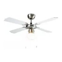
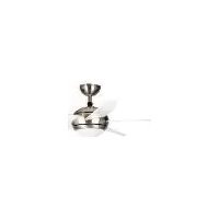
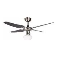
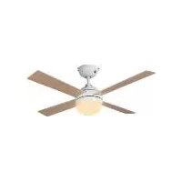
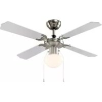
Modern white and gray ceiling fan with four blades, featuring a spherical head and top hub (no text or symbols visible)DECKENVENTILATOR MIT LED-LEUCHTE / CEILING FAN WITH LED LIGHT / VENTILATEUR DE PLAFOND AVEC ÉCLAIRAGE LED
DE AT CH
DECKENVENTILATOR MIT LED-LEUCHTE
Assembly, operating and safety instructions
NL BE
PLAFONDVENTILATOR MET LED-LAMP
Before reading, unfold the pages containing the illustrations and familiarise yourself with all functions of the device.
FR BE
natural_image
Line drawing of a mobile phone with no visible text or symbols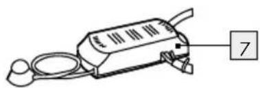
natural_image
Line drawing of a handheld electronic device with a labeled component (no text or symbols present)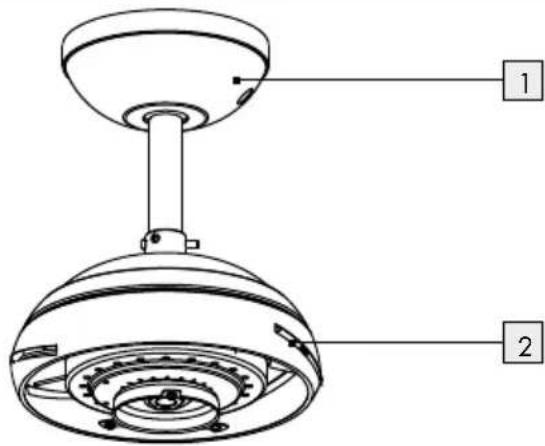
text_image
Technical diagram of a mechanical device with labeled parts 1 and 2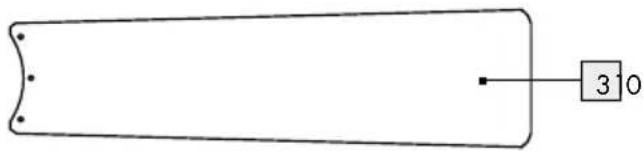
natural_image
Simple line drawing of a rectangular object with a labeled square and number 3 (no text or symbols beyond basic markings)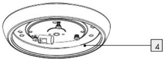
natural_image
Technical line drawing of a circular mechanical component with internal components and a numbered label (4) pointing to the end.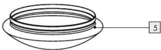
natural_image
Simple line drawing of a bowl-like structure with a numbered label '5' pointing to the side (no text or symbols on the diagram itself)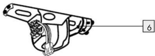
natural_image
Technical line drawing of a mechanical component with no visible text or symbols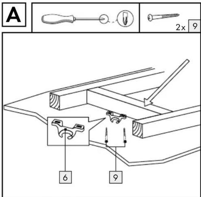
text_image
A 2x 9 6 9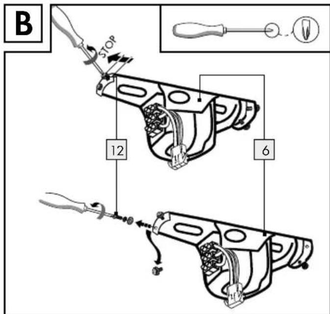
text_image
B STOP 12 6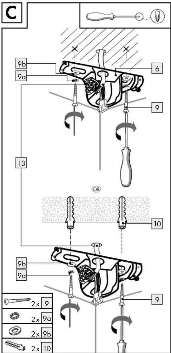
text_image
C 9b 9a 6 9 13 OR 10 9b 9a 2x 9 2x 9a 2x 9b 2x 10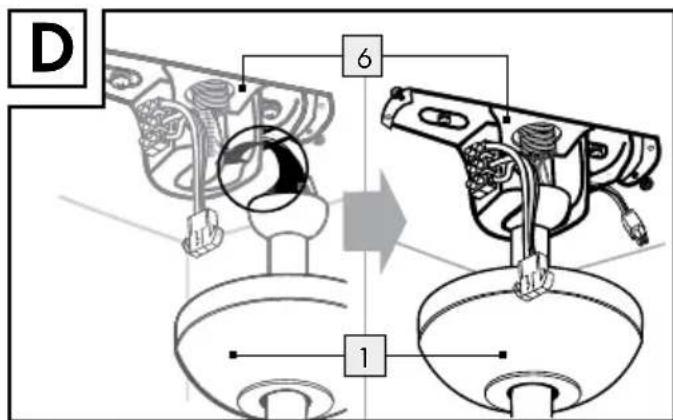
text_image
D 6 1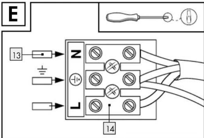
text_image
E 13 + - - 14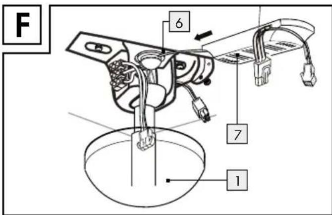
text_image
F 6 7 1(Deckenventilator): 50 W
Max. zulässige
EDI Light Service Center
Kleinbahnstraße 35
59759 Arnsberg
DEUTSCHLAND
E-Mail: info@edi-light.com
Telefon: +49 2932 639 773
Österreich
EDI Light Service Center
Heiligkreuz 22
6136 Pill
AUSTRIA
E-Mail: info@edi-light.com
Telefon: +43 5242 670 57
Schweiz
EGLO Schweiz AG
Seetalstraße 142
6032 Emmen
SCHWEIZ
E-Mail: info-switzerland@eglo.com
Telefon: +41 41 268 69 59
IAN 329949\_1910
Intended use......Page 21
Scope of delivery....Page 21
Parts description......Page 21
Technical data......Page 21
Safety Page 22
Safety notes....Page 22
Safety instructions for batteries/rechargeable batteries Page 23
Preparation......Page 24
Tools and materials required......Page 24
Prior to installation......Page 24
Assembly Page 24
Installing the product......Page 24
Initial use Page 25
Operating the ceiling fan with LED light....Page 25
Setting up clockwise/anti-clockwise rotation Page 26
Operating the ceiling fan with LED light using the remote control......Page 26
Replacing the batteries....Page 26
Troubleshooting Page 27
Replacing the LED light bulb....Page 27
Maintenance and cleaning......Page 28
Disposal Page 28
Warranty and service......Page 28
Warranty Page 28
Service address......Page 29
Declaration of conformity....Page 29
Warranty card....Page 29
| List of pictograms used | |||
 | Read the instructions! |  | Risk of accidents and danger to life for infants and children! |
| Safety instructionsInstructions for use |  | Warning! Danger of electric shock! | |
| This product is only suitable for use indoors, in dry and enclosed spaces. |  | Caution - hot surfaces! | |
| V~ | Volts (alternating current/voltage) |  | Caution! Danger of explosion! |
| Hz | Hertz (frequency) Earth wire (protection cl |  | |
| W | Watts (effective power) LED light bulb dimenions | ||
| LED operating life | 60% of the light intensity is achieved in less than 1 second. | ||
| This ceiling fan with LED light is not suitable for dimmers or electronic switches. | 2 type AAA batteries included | ||
| E27 LED light bulb included | |||
| Only install the light bulb in a dry environment. | Wear safety gloves! | ||
| IP20 | Protection type: no protection against water!Suitable for indoor use only. | Dispose of the packaging and the product in an environmentally friendly manner! | |
| 3 speed settings available | Improper disposal of batteries can harm the environment! | ||
| Switching cycles Certified with the DEKRA | |||
| For your safety! | Product meets the applicable Euro-pean product-specific directives. | ||
| Observe the warnings and safety notes! | |||
Ceiling fan with LED light
●Introduction

Congratulations on the purchase of your new ceiling fan with LED light. You have chosen a high-quality product. Please be
sure to carefully read all the instructions for use. Unfold the pages with the illustrations. These instructions are a part of this ceiling fan with LED light and contain important information on setup and operation. Always observe all safety information. Before using this product for the first time, verify that the correct voltage is present and that all parts are properly installed. If you have any questions or are unsure
about operating the ceiling fan with LED light, please contact your retailer or the service centre. Please keep these instructions in a safe place and include them when passing this product on to others.
Intendeduse
This ceiling fan with LED light is solely suitable for use in dry, closed indoor spaces. It is not suitable for use in bathrooms or other consistently damp areas. Neither is it suitable for use in tropical climates. This ceiling fan with LED light is only intended for private household use. Do not operate at temperatures over 40 °C.
- Scope of delivery
Always check that all parts are present and that the ceiling fan with LED light is in perfect condition immediately after unpacking.
1 Ceiling fan unit
4 Fan blades
1 Lighting unit
1 Lampshade (glass)
1 LED bulb (E27, 6 W)
1 Mounting bracket
1 Receiver
1 Remote control (incl. 2 batteries, type AAA)
2 Fastening screws (mounting bracket)
2 Spring lock washers
2 Washers
2 Wall plugs
3 Screws (lighting unit)
1 Set of assembly instructions and instructions for use incl. warranty card
Partsdescription
1 Cover (ceiling fan unit)
2 Motor housing (ceiling fan unit)
3 Fan blade
4 Lighting unit
5 Lampshade
6 Mounting bracket
7 Receiver
8 Remote control
9 Fastening screws (mounting bracket)
9a Spring lock washer (mounting bracket)
9b Washer (mounting bracket)
10 Wall plug
11 Screws (lighting unit)
12 Screw (cover)
13 Power cord (external)
14 Lustre terminal
15 Connection cable (mounting bracket)
16 Connection socket (motor housing)
17 Sensor unit
18 Screw (fan blade)
19 Connector plug (motor housing)
20 Connection socket (lighting unit)
21 LED light bulb
22 Socket
23 Rotation direction switch
24 LED indicator
Remote control buttons 8:
25 HI button (ceiling fan)
26 MED button (ceiling fan)
27 LOW button (ceiling fan)
28 OFF button (ceiling fan)
29 OFF button (LED light)
30 ON button (LED light)
●Technicaldata
Item number: 55461
Operating voltage: 220-240V\~50Hz
Total output (ceiling fan): 50 W
Max. permissible light
bulb wattage: 60W
Wattage in standby mode: 0.31 W
Rotational speed: 230 rpm
Noise level: 52 dB(A)
LED light bulb output: E27, 6 W
Dimensions: Body height: 36 cm
Ceiling fan
diameter: 107 cm
Protection class: 1/⊥
IP rating: IP20
Batteries: 2 x 1.5 V, type AAA
Distributor:
Edi Light GmbH, Heiligkreuz 22, 6136 Pill, AUSTRIA
www.edi-light.com
●Safety

Safety notes
The information included in these instructions for use is for your own safety. Please read it carefully before installing the device and keep the instructions for later consultation. Damage due to failure to comply with these instructions for use will void the warranty! We assume no liability for consequential damage! We assume no liability for property damage or personal injury due to improper handling or failure to observe the safety information!

RISK OF WARNING!
CIDENT AND DANGER TO LIFE FOR INFANTS AND CHILDREN!
This ceiling fan with LED light may be used by children aged 8 years and up, as well as by persons with reduced physical, sensory or mental capacities, or those lacking experience and knowledge, as long as they are supervised or instructed in the safe use of the product and they understand the associated risks. Do not allow children to play with the product. Never allow children to clean or maintain this product unsupervised.
Do not leave the product or packaging material lying unattended. Plastic films or bags, or plastic parts etc. can turn into dangerous toys for children.

Avoid the risk of fatal injury from electric shock
■ Ensure that any electrical installation is performed by a qualified electrician or a person trained to carry out electrical installations, in compliance with the applicable standards.
■ Never use the product if it is damaged in any way.
■ Remove the fuse or switch off the circuit breaker (0 setting) in the fuse box prior to installation.
■ Always avoid any contact between the ceiling fan or the LED light and water or other liquids.
■ Never open any of the electrical equipment or insert any objects into this equipment. Such interferences pose a risk of fatal injury from electric shock.
Prior to installation, make sure that the available mains voltage corresponds to the required operating voltage of the ceiling fan (see "Technical data").
- Be sure not to damage any wires during installation.
- Do not install the light on damp or conductive surfaces.
This ceiling fan with LED light is not suitable for dimmers or electronic switches.
Only insert the light bulb in a dry environment.

Prevent fire and injury hazards


CAUTION! RISK OF BURNS DUE TO HOT SURFACES! To prevent burns, ensure that the product has
been switched off and has cooled down before touching the LED light. Illuminants become very hot.
Before mounting the ceiling fan, make sure that the mounting location has a load capacity of at least 45 kg.
Do not look directly into the light source. Do not look at the light source with an optical instrument (e.g. magnifying glass).
- Replace defective light bulbs with new ones immediately. Before changing the light bulb, make sure that the circuit to which the product is connected is not live. To do so, remove the fuse or switch off the circuit breaker in the fuse box (position 0).
- Only use lamps of the specified type (see type plate and "Technical data").
- Allow the LED light to cool down for at least 15 minutes before replacing a defective bulb.
- Do not under any circumstances use the product to store or hang up other objects.
DO NOT insert any objects into the fan blades during operation, as this may damage the ceiling fan and cause injury.
DO NOT use the ceiling fan in the same room and at the same time as gas-powered devices.
■ Never use the connection cable to carry the weight of the product.
WARNING: unusual oscillations, stop using the ceiling fan immediately and consult qualified personnel.
- Should doubts arise during assembly / use of the product, consult a qualified electrician.
The replacement of safety suspension parts must be carried out by the manufacturer, his customer service representatives or suitably qualified persons.

Avoid the risk of property damage!
- Install the ceiling fan in a location where it is protected from moisture and dirt.
A ceiling height of at least 2.55 m is required for safe operation. The fan blades must be at least 2.3 m away from the floor and 0.6 m away from the nearest wall or item of furniture. The ceiling to which the product is mounted may slope by a maximum of 14°.
■OnlyuseOEM parts. The use of non-standard or solid-state dimmer controllers may result in loss of performance and cause permanent damage to the product, which is excluded from warranty.
Do not operate the ceiling fan if the ambient air temperature is over 40 °C. - Unpack the ceiling fan carefully on a soft surface to avoid damaging the surface of the ceiling fan.
- Do not lay the motor housing on its side, as this could bend and damage the decor housing.

For your safety!
Always be alert! Always pay attention to what you are doing and always use common sense.
- Do not install the product if you are having difficulty concentrating or do not feel well.
■ efBre use, familiarise yourself with all the instructions and diagrams in these instructions, as well as with the product itself.

Safety instructions for batteries/rechargeable batteries
■ DANGER TO LIFE! Keep batteries/rechargeable batteries out of reach of children. If accidentally swallowed seek immediate medical attention.
■ Swallowing may lead to burns, perforation of soft tissue, and death. Severe burns can occur within 2 hours of ingestion.
DANGER OF EXPLOSION!

Never recharge non-rechargeable batteries. Do not short-circuit batteries / rechargeable batteries and / or open them. Overheating, fire or bursting can be the result.
■ Never throw batteries / rechargeable batteries into fire or water.
Do not exert mechanical loads to batteries / rechargeable batteries.
Risk of leakage of batteries / rechargeable batteries
- Avoid extreme environmental conditions and temperatures, which could affect batteries / rechargeable batteries, e.g. radiators / direct sunlight.
If batteries / rechargeable batteries have leaked, avoid contact with skin, eyes and mucous membranes with the chemicals! Flush immediately the affected areas with fresh water and seek medical attention!
WEAR PROTECTIVE GLOVES!
Leaked or damaged batteries / rechargeable batteries can cause burns on contact with the skin. Wear suitable protective gloves at all times if such an event occurs.
In the event of a leakage of batteries / rechargeable batteries, immediately remove them from the product to prevent damage.
Only use the same type of batteries / rechargeable batteries. Do not mix used and new batteries/rechargeable batteries.
■ Remove batteries / rechargeable batteries if the product will not be used for a longer period.
Risk of damage of the product
Only use the specified type of battery / rechargeable battery!
Insert batteries / rechargeable batteries according to polarity marks (+) and (-) on the battery / rechargeable battery and the product.
Use a dry lint-free cloth or cotton swab to clean the contacts on the battery / rechargeable battery and in the battery compartment before inserting!
■ Remove exhausted batteries/rechargeable batteries from the product immediately.
■ Ensure that there is a minimum distance of 300 mm between the fan blades and the nearest objects and walls at the installation site.
Make sure that the fan blades are at least 2.3 m above the ground.
Prior to installation, make sure that the installation site is suitable to bear the weight of the product. You may need to install a wooden support between two ceiling beams (see Fig. A).
- Assembly
●Preparation
- Tools and materials required
The specified tools and materials are not included. The information and values specified are non-binding and are only provided as a reference. The nature of the material is determined by the specific local conditions.
- Pencil / marking tool
- Voltage tester
- Cross-head and slotted head screwdriver
- Power drill
- Drill bit
- Side cutters
- Ladder
- Pliers
Note: DO NOT use power tools to tighten the screws. Excessive tightening can damage the thread of the screws.
- Prior to installation
■ Prior to installation, familiarise yourself with all the instructions and diagrams in this manual as well as with the ceiling fan itself.
Before installation ensure that the circuit to which the product will be connected is not live. To do so, remove the fuse or switch off the circuit breaker in the fuse box (position 0).
- Verify that the components are not live using a voltage tester.
Note: You will need a power drill for the installation work.
Note: Please also follow the instructions for your power drill.
Note: The supplied fixing screws 9 are intended for use with wooden ceiling beams; for all other materials the appropriate fixing screws must be purchased. Ask a specialist shop for suitable screws and plugs for your ceiling.
Note: The mounting bracket 6 of the ceiling fan allows it to be mounted on angled / sloped ceilings up to an inclination of 14°.
WARNING! Please be sure not to drill into any electrical wiring, gas or water lines inside the wall.
- Installing the product
Note: Place the ceiling fan on a soft surface when unpacking to avoid damaging the surface of the ceiling fan.
Note: Do not lay the motor housing 2 on its side, as this could bend and damage the decor housing.
Note: Remove all packaging materials from the ceiling fan with LED light.
Installing the mounting bracket:
WARNING! DANGER OF ELECTRIC SHOCK!
■ Remove the fuse or switch off the circuit breaker (0 setting) in the fuse box prior to installing the mounting bracket 6.
☐ Unscrew the right-hand screw 12, including the washer and tooth lock washer, which is located at the side of the mounting bracket 6.
□ Unscrew the left-hand screw 12 together with the washer and tooth lock washer (see Fig. B).
☐ Mark the drill holes using the holes in the mounting bracket 6 intended for the fixing screws 9 as a guide.
Now drill the mounting holes. Make sure that you do not damage the power cord (external) ^13 , water pipes or electrical cables.
☐ Insert the wall plugs 10 into the drilled holes. If necessary, use a hammer to help you.
IMPORTANT! The chosen installation location must be able to hold the total weight of the ceiling fan with LED light.
☐ Guide the power cord (external) 13 through the intended central hole in the mounting bracket 6. Attach the mounting bracket 6 using the washers 9b, spring lock washers 9a and fixing screws 9 provided (see Fig. C). Make sure that at least 30 mm of the fixing screw 9 is screwed into the ceiling beam or wooden support.
Installing the ceiling fan: ⚠ WARNING! DANGER OF ELECTRICSHOCK!
Before proceeding with the installation, make sure that the power supply to which the product is connected is not live. To do so, remove the fuse or switch off the circuit breaker in the fuse box (position 0).
Using one of the holes intended for this purpose, hang the cover 1 on the hook on the mounting bracket 6. The mounting bracket 6 is provided with a lug which must be aligned with the corresponding groove on the ball joint of the cover 1 (see Fig. D).
Connect the connection cable (external) 13 with the lustre terminal 14 in the mounting bracket 6. Also ensure to connect the correct coloured wires (live wire, black or brow = symbol L, neutral wire, blue = symbol N, earth wire ⊥ = green-yellow) (see Fig. E).
☐ Insert the receiver 7 between the mounting bracket 6 and ball joint (see Fig. F).
☐ Insert the connecting cables 15 of the mounting bracket 6 into the connection sockets 16 of the motor housing 2. Make sure that the connections are firmly connected (see Fig. G).
☐ Insert the sensor unit 17 of the receiver 7 into the opening provided for this purpose in the cover 1 (see Fig. H).
Place the cover 1 on the mounting bracket 6 by tightening the screws 12 with the washer and tooth lock washer (see Fig. I). Make sure that all screws are tightened securely.
Remove the pre-installed screws 18 and spring lock washers on the motor housing 2.
☐ Attach the fan blades 3 to the motor housing 2. Use the screws 18 and spring lock washers pre-installed on the motor housing 2 (see Fig. J). Make sure that all the fan blades 3 have either the side with the wood effect or the white site facing downwards.
Connecting the ceiling fan:
☐ Insert the connector plug 19 of the motor housing 2 firmly into the connection socket 20 of the lighting unit 4 (see Fig. K).
☐ Fasten the lighting unit 4 to the motor housing 2 with the screws 11 and the tooth lock washers (see Fig. L). Ensure that the cables do not become trapped.
☐ Screw the LED light bulb 21 clockwise into the socket 22 (see Fig. M). Please refer to the chapter "Technical data" to find out which LED light bulb is required.
Place the lampshade 5 on the lighting unit 4 by turning the lampshade 5 clockwise (see Fig. M).
☐ Replace the fuse or switch on the circuit breaker (I setting) in the fuse box.
Your ceiling fan with LED light is now ready to use.
- Initial use
- Operating the ceiling fan with LED light
You can switch the ceiling fan and the LED light on / off and adjust the rotation speed of the ceiling fan
using the remote control 8 (see chapter "Operating the ceiling fan with LED light using the remote control").
- Setting up clockwise / anti-clockwise rotation
CAUTION! RISK OF INJURY! Always switch the ceiling fan off and wait until it is still before using the rotation direction switch 23. Operating the rotation direction switch 23 while the ceiling fan is on can lead to injuries and / or material damage.
Winter:
☐ In low temperatures, slide the rotation direction switch 23 upwards. The ceiling fan will rotate clockwise and distribute the heat in the room (see Fig. N).
Summer:
☐ In high temperatures, slide the rotation direction switch 23 downwards. The ceiling fan will rotate anti-clockwise and generate a cooling airflow (see Fig. N).
- Operating the ceiling fan with LED light using the remote control (see Fig. O)
The following functions can only be operated using the remote control 8.
Note: The LED indicator 24 flashes red when a function is selected using the remote control.
Note: Before using the remote control 8, make sure that there are no obstacles between the transmitter on the remote control 8 and the receiver 7. If the remote control 8 does not function properly, refer to the chapter "Troubleshooting".
| Controlling the ceiling fan | |
| HI 25 | Set the rotation speed of the ceiling fan (high) |
| MED 26 | Set the rotation speed of the ceiling fan (medium) |
| LOW 27 | Set the rotation speed of the ceiling fan (low) |
| OFF 28 | Switch off the ceiling fan |
| Controlling the LED light | |
| OFF 29 | Switch the LED light off |
| ON 30 | Switching the LED light on |
● Replacing the batteries
Note: Low voltage in the batteries can affect operation and signal reception. The LED indicator 24 flashes when the battery is low. Replace the battery immediately.
Open the battery compartment cover located on the back of the remote control 8.
☐ Remove the depleted batteries.
☐ Insert two new batteries of the specified type (see chapter "Technical data") into the battery compartment. Ensure that the polarity is correct, as indicated in the battery compartment.
☐ Close the battery compartment cover.
Note: If you are not going to use the ceiling fan with LED light for a long period of time, remove the batteries from the remote control 8.
●Troubleshooting
| Faults Cause Solution | ||
| The ceiling fan and LED light cannot be controlled via the remote control 8. | Batteries are not inserted correctly or are depleted. | ☐ Check that the batteries in the remote control 8 are inserted according to the polarity indicated.☐ Insert new batteries into the remote control 8 if necessary.☐ Low voltage in the batteries can affect operation and signal reception. The LED indicator 24 flashes when the battery is low. Replace the battery immediately. |
| The receiver 7 and transmitter may be disturbed by obstacles or by other radio frequencies or remotely controlled devices. | ☐ Make sure that there are no obstacles in the way or reduce the distance between the remote control 8 and the receiver 7.☐ If necessary, remove other remotely controlled devices from the vicinity of the receiver 7 or switch them off. | |
| The ceiling fan with LED light is not working even though the remote control 8 is working and there is no fault. | Fuse is removed or circuit breaker switched off / defective. | ☐ Switch off the ceiling fan with LED light.☐ Check the fuse or circuit breaker. |
WARNING! If you notice unusual oscillations, stop using the ceiling fan immediately and consult qualified personnel. Do not attempt to repair the ceiling fan yourself.
● Replacing the LED light bulb
WARNING! DANGER OF ELECTRIC SHOCK!
Before changing the light bulb, make sure that the power supply to which the product is connected is not live. To do so, remove the fuse or switch off the circuit breaker in the fuse box (position 0).
CAUTION! RISK OF BURNS DUE TO HOT SURFACES! Allow the LED light to cool off completely.
Remove the lampshade 5 from the lighting unit 4 by turning the lampshade 5 anticlockwise.
☐ Use a clean, lint-free cloth to replace the bulb.
□ Unscrew the defective LED light bulb 21 from the socket 22 anti-clockwise.
☐ Screw the new LED light bulb 21 clockwise into the socket 22. Please refer to the chapter "Technical data" to find out which LED light bulb is required.
Place the lampshade 5 back on the lighting unit 4 by turning the lampshade 5 clockwise (see Fig. M).
☐ Replace the fuse or switch on the circuit breaker (I setting) in the fuse box.
● Maintenance and cleaning
WARNING! DANGER OF ELECTRIC SHOCK! Always disconnect the product from the mains before cleaning. To do
so, remove the fuse or switch off the circuit breaker in the fuse box (position 0).

WARNING! DANGER OF ELECTRIC
SHOCK! To ensure electrical safety, never clean the product with aggressive
detergents or immerse it in water.

CAUTION! RISK OF BURNS DUE TO HOT SURFACES! Allow the LED light to cool off completely.
- Do not use solvents, petrol, etc. Doing so would damage the product.
☐ Only clean with a dry, fluff-free cloth.
☐ Use a duster to clean the fan blades 3.
☐ Replace the fuse or switch on the circuit breaker (I setting) in the fuse box. - Check that all screws are properly tightened every 6 months. The movement of the ceiling fan can cause the screws to loosen.
●Disposal
The packaging is made entirely of recyclable materials, which you may dispose of at local recycling facilities.
Observe the marking of the packaging materials for waste separation, which are marked with abbreviations (a) and numbers (b) with following meaning: 1-7: plastics / 20-22: paper and fibre-board/80-98: composite materials.

The product and packaging materials are recyclable, dispose of it separately for better waste treatment. The Triman logo is valid in France only.
Contact your local refuse disposal authority for more details of how to dispose of your worn-out product.
To help protect the environment, please dispose of the product properly when it has reached the end of its useful life and not in the household waste. Information on collection points and their opening hours can be obtained from your local authority.
Faulty or used batteries / rechargeable batteries must be recycled in accordance with Directive 2006/66/EC and its amendments. Please return the batteries/rechargeable batteries and/or the product to the available collection points.
Environmental damage through incorrect disposal of the batteries / rechargeable batteries!
Batteries / rechargeable batteries may not be disposed of with the usual domestic waste. They may contain toxic heavy metals and are subject to hazardous waste treatment rules and regulations. The chemical symbols for heavy metals are as follows: Cd = cadmium, Hg = mercury, Pb = lead. That is why you should dispose of used batteries / rechargeable batteries at a local collection point.
● Warranty and service
Warranty
We provide a 3-year warranty from the date of purchase. Our products are manufactured using modern production methods and are subject to precise quality control. We guarantee that this product is in perfect condition. During the warranty period we will remedy any defects in material or manufacture free of charge. In the event of an unexpected defect, please return the carefully packaged product to the service address specified.
The warranty does not extend to damage due to improper operation, or to wear parts and consumables. These can be ordered from the telephone number listed for a charge. Repairs not covered by the warranty (e.g. light bulbs) may also be requested at cost price from the service address listed.
The product will be repaired at the specified service location. Timely processing and returns can only be ensured by sending the product directly to this address.
If you would like additional product information, need to order accessories or if you have a question about the service process, please contact our customer service department on the telephone number specified. Please include the item number (see "Technical data") when enquiring about the product.
●Serviceaddress
Great Britain/Ireland
EGLO UK Ltd.
Unit 12 Cirrus Park
Lower Farm Road
Moulton Park Industrial Estate
Northampton, NN3 6UR, GREAT BRITAIN
E-Mail: info-greatbritain@eglo.com
Phone: +44 1604 790 986
IAN 329949\_1910
Please have your receipt and item number (e.g. IAN 123456_7890) ready as your proof of purchase when enquiring about the product.
● Declaration of conformity CE

This product fulfils the requirements of the applicable European and national directives. The relevant declarations and
documents are held by the manufacturer. This product meets the requirements of the German Equipment and Product Safety Act.
We reserve the right to make technical and visual changes to the product in the interest of product improvement. Typographical and printing errors excepted.

Warrantycard
Return address:
Name/First name:
Country/Postal code/City/Street address:
Phone number:
Item number / Description:
Purchase date / Point of purchase:
Description of the defect:
Date / Signature:
Non-warranty cases:

Please return the un-repaired item, carriage paid.

Please inform me of the costs. Repair the product for a fee.
EGLO Belgium B.V.B.A.
Antwerpsesteenweg 247
2950 Kapellen, BELGIQUE
E-mail: info-belgium@eglo.com
Telefoon: +32-3-250 60 80
IAN 329949\_1910
EGLO Belgium B.V.B.A.
Antwerpsesteenweg 247
2950 Kapellen, BELGIË
E-mail: info-belgium@eglo.com
Telefoon: +32-3-250 60 80
IAN 329949\_1910
NOSTE OCHRANNÉ RUKAVICE!

text_image
N 23 WINTER CLOCKWISE Blade Rotation SUMMER COUNTER-CLOCKWISE Blade Rotation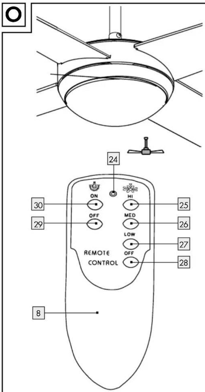
text_image
ON OFF HI MED LOW OFF REMOTE CONTROL 24 30 29 25 26 27 28 8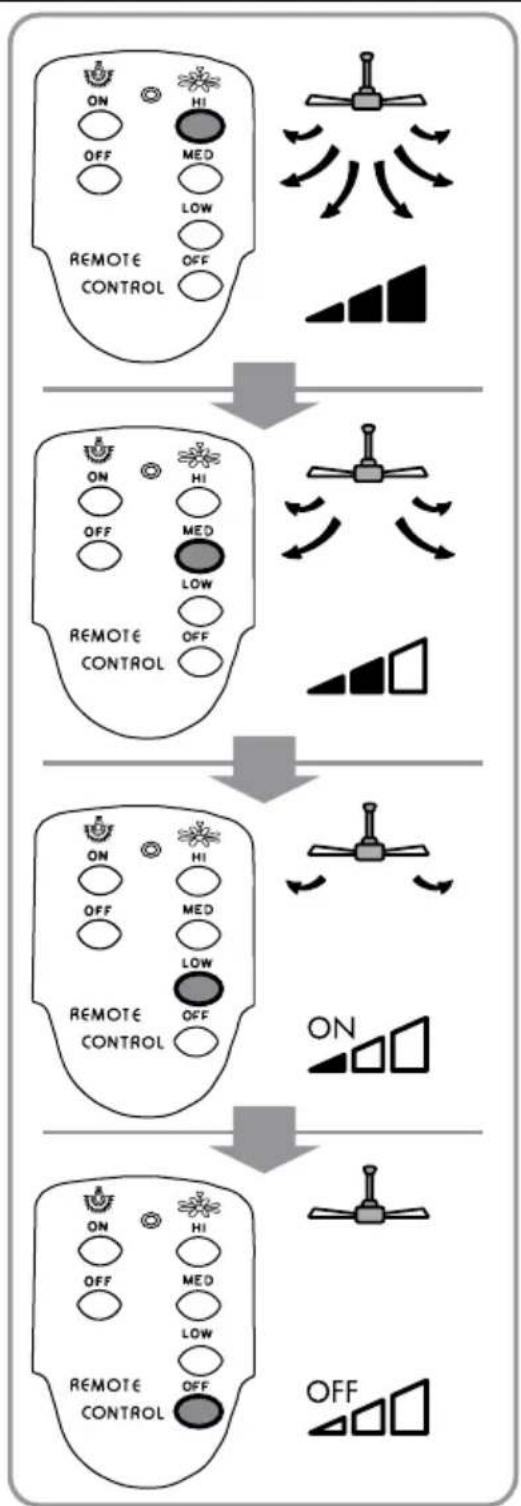
flowchart
graph TD
    A["ON"] --> B["HI"]
    C["OFF"] --> D["MED"]
    E["LOW"] --> F["OFF"]
    G["REMOTE CONTROL"] --> H["OFF"]
    I["ON"] --> J["HI"]
    K["OFF"] --> L["MED"]
    M["LOW"] --> N["OFF"]
    O["REMOTE CONTROL"] --> P["OFF"]
    Q["ON"] --> R["HI"]
    S["OFF"] --> T["MED"]
    U["LOW"] --> V["OFF"]
    W["REMOTE CONTROL"] --> X["OFF"]
    Y["ON"] --> Z["HI"]
    AA["OFF"] --> AB["MED"]
    AC["LOW"] --> AD["OFF"]
    AE["REMOTE CONTROL"] --> AF["OFF"]
EDI Light GmbH
Heiligkreuz 22
6136 Pill
AUSTRIA
text_image
FSC MIX FSC® C142868