SWL R1300 - Sweeper Lavor - Free user manual and instructions
Find the device manual for free SWL R1300 Lavor in PDF.
| Product type | Assisted front-discharge ride-on sweeper |
| Brand | Lavor |
| Model | SWL R1300 |
| Power supply | Diesel |
| Engine | Kubota D722-EF01, 14.7 kW at 3600 rpm |
| Cleaning width (with 1 side brush) | 1300 mm |
| Cleaning width (with 2 side brushes) | 1600 mm |
| Waste container capacity | 490 L |
| Maximum forward speed | 12 km/h |
| Working speed | 8 km/h |
| Maximum slope | 18% |
| Weight (standard version) | 950 kg |
| Dimensions (L x W x H) | 2250 x 1450 x 1540 mm |
| Filtering surface | 8 m² (1 pocket filter) |
| Maximum cleaning capacity | 19200 m²/h |
| Transmission | Hydraulic |
| Traction | Rear |
| Guaranteed sound level | 92 dB(A) |
| Suction system | Pocket filter with shaker |
| Safety devices | Seat belt, automatic stop if operator stands up, container safety bar |
| Routine maintenance | Engine oil change every 90-100 h, air filter cleaning every 25 h, check dust seals every 70-100 h |
Frequently Asked Questions - SWL R1300 Lavor
User questions about SWL R1300 Lavor
0 question about this device. Answer the ones you know or ask your own.
Ask a new question about this device
Download the instructions for your Sweeper in PDF format for free! Find your manual SWL R1300 - Lavor and take your electronic device back in hand. On this page are published all the documents necessary for the use of your device. SWL R1300 by Lavor.
USER MANUAL SWL R1300 Lavor
text_image
QR code image containing encoded data, no visible human-readable textDIFFERENZIA I RIFIUTI SEPARATE THE WASTE
MANUALE USO E MANUTENZIONE motoscopa
IT pag. 2
INSTRUCTIONS AND OPERATING MANUAL Sweeper
EN pag. 39
MANUEL D'INSTRUCTION Motobalayeuse
FR page 73
Technical data plate
CE
indice....pag.
CAPITOLO 1 - NORME GENERALI 4
CAPITOLO 2 - SCOPI / INTENZIONI. . . . . . . . . . . . . . . . . . . . . . . . . . . . . . . . . . . . . . . . . . . . . . . . . . . . . . . . . . . . . . . . 5
text_image
EACCE Made in Italy Type S/N Code Year / Week Weight Kg KW PO n. Volts LwA dB 2 %text_image
Technical diagram of a vehicle's internal components with numbered parts for identification.Figura 1
text_image
Technical diagram of a mechanical device with numbered components and exploded view, likely for assembly or maintenance purposes.Figura 2
text_image
Technical diagram of a mechanical vehicle with numbered parts labeled 1, 2, and 3Figura 3
3.4. SPAZZOLA CENTRALE
natural_image
Technical line drawing of a mechanical device with labeled components (no text or symbols present)Figura 4
3.8. CONTENITORE RIFIUTI
text_image
Technical diagram of a mechanical device with numbered parts and directional arrows indicating motion or assembly.Figura 5
3.9. FLAP CONTENITORE
natural_image
Technical line drawing of a mechanical agricultural machine with a multi-barrel tower and wheels (no text or symbols)
natural_image
Pure technical line drawing of a mechanical component with no text or symbols
natural_image
Technical line drawing of a mechanical component with an arrow indicating direction (no text or symbols)Figura 6
3.10. DATI TECNICI
CARATTERISTICHE TECNICHE U.M. SWL R 1300
natural_image
Technical line drawing of a ship's interior and steering wheel (no text or symbols)Figura 8

natural_image
Technical line drawing of a car interior showing structural components and airflow direction (no text or symbols)

natural_image
Technical line drawing of a vehicle interior showing engine compartment and structural components (no text or symbols)
natural_image
Illustration of a rolled-up document with an arrow pointing upward (no text or symbols)
natural_image
Technical line drawing of a car interior showing engine and dashboard components (no text or symbols)
natural_image
Diagram of a mechanical component with internal forces and arrows, labeled 'C' (no text or symbols beyond label)Figura 9
text_image
Diagram of a vehicle steering system with labeled components and directional arrows indicating motion or movement.Figura 10
text_image
Technical diagram of a mechanical device with labeled components 1 and 2Figura 11
4.3. DISPOSITIVI DI COMANDO
text_image
Technical diagram of a mechanical device with numbered components for identification and assembly reference.Figura 12
text_image
OFF ON GL ST -100V -100VFigura 13
4.3.4. PEDALE ACCELERATORE
natural_image
Technical diagram of a mechanical component with directional arrows indicating movement or force (no text or symbols present)Figura 14
natural_image
Diagram of three vertical cylindrical components with red arrows indicating flow or movement, mounted on a mechanical base (no text or symbols present)Figura 15
4.3.9. COMANDO SPAZZOLA CENTRALE
natural_image
3D mechanical assembly diagram showing directional arrows and component placement (no text or symbols)Figura 16
4.3.11. INTERRUTTORE SPAZZOLA LATERALE
flowchart
graph TD
    A["Control Panel"] --> B["Leftmost Panel"]
    B --> C["Leftmost Panel with Arrow pointing inward"]
    C --> D["Rightmost Panel with Red Arrow indicating clockwise rotation"]
    D --> E["Leftmost Panel with Arrow pointing inward"]
    E --> F["Leftmost Panel with Red Arrow indicating clockwise rotation"]
    F --> G["Rightmost Panel with Light Arrow indicating clockwise rotation"]
Figura 17
natural_image
Technical line drawing of a mechanical frame assembly (no text or symbols)
text_image
A - B CFigura 20

text_image
B AFigura 21 Figura 22

text_image
B
natural_image
Close-up of a gray electronic device with a red 'C' label and a black control switch (no readable text or symbols beyond the label)Figura 23
natural_image
Technical line drawing of a mechanical assembly with two views (top and side), showing internal components and structural details (no text or symbols present)Figura 25
natural_image
Technical line drawing of an industrial machine interior with a magnified inset showing internal components (no text or symbols)Figura 26
natural_image
Technical line drawing of a mechanical device with visible components and mounting base (no text or symbols)
natural_image
Technical line drawing of a mechanical device with exploded view and close-up insets (no text or symbols)Figura 27
natural_image
Technical line drawing of a mechanical device with internal components and a magnified inset showing a close-up detail (no text or symbols)Figura 28


natural_image
Technical line drawing of a mechanical component with an arrow indicating direction (no text or symbols present)
natural_image
Technical diagram of a mechanical component with a black arrow pointing to a specific feature (no text or symbols present)Figura 30
natural_image
Technical line drawing of a mechanical component with a black arrow indicating direction (no text or symbols)
natural_image
Technical line drawing of a mechanical component with no visible text or symbolsFigura 31
natural_image
Technical diagram of a mechanical device with directional arrows indicating motion or force (no text or symbols present)Figura 32
natural_image
Technical line drawing of a mechanical device with internal components and a magnified inset showing tool path (no text or symbols)Figura 38

text_image
Technical diagram of a cleaning or dust removal device with labeled parts and exploded viewsFigura 39
text_image
Technical diagram of a device with numbered components and labeled partsFigura 41
natural_image
Technical line drawing of a mechanical device with a 700-unit dimension标注 (no text or symbols present)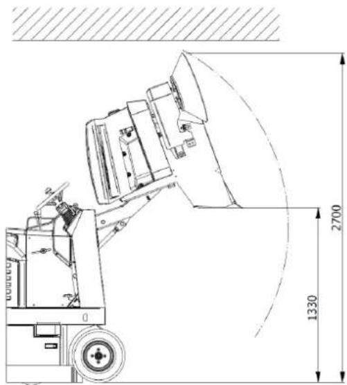
text_image
2700 1330Figura 42

VERIFICARE CHE NON VI SIANO PERSONE A MENO DI 2 METRI DALLA MOTOSCOPA DURANTE LE OPERAZIONI DI SVUOTAMENTO DEL CONTENITORE RIFIUTI. VERIFICARE INOLTRE CHE VI SIA SPAZIO ADEGUATO PER EVITARE URTI CHE POTREBBERO DANNEGGIARE LA MOTOSCOPA COMPROMETTENDONE IL FUNZIONAMENTO.

natural_image
Technical line drawing of a mechanical device with labeled parts and mounting holes (no text or symbols present)Figura 43
CAPITOLO 12 - TRASPORTO, MOVIMENTAZIONE E FUORI SERVIZIO
12.1. MESSA FUORI SERVIZIO

text_image
Technical diagram of a mechanical assembly with numbered components labeled 1 to 4
text_image
Technical diagram of a machine with numbered components labeled 5, 6, and 7Figura 44
14.4. SPAZZOLA CENTRALE

OPERAZIONE DA ESEGUIRSI A MOTORE SPENTO E FREDDO MUNITI DI GUANTI, OCCHIALI DI SICUREZZA E DISPOSITIVI DI PROTEZIONE DELLE VIE RESPIRATORIE. PROCEDERE ALL'ISPEZIONE SOLO DOPO AVER INSERITO LA BARRA DI SICUREZZA (PAR. 4.4.1).
text_image
Technical diagram of a mechanical device with numbered components for identificationFigura 45
text_image
Technical diagram of a 3D printing machine with labeled parts, showing assembly and component details.Figura 47
14.6. MANUTENZIONI SPECIFICHE PER MOTORI A COMBUSTIONE INTERNA


CHAPTER 9 - ADJUSTMENTS....61
CHAPTER 10 - SAFETY RULES....62
CHAPTER 11 - STABILITY OF THE MACHINE....64
CHAPTER 12 - TRANSPORTATION, HANDLING AND DECOMMISSIONING ..... 65
CHAPTER 13 - EMERGENCY SITUATIONS....65
CHAPTER 14 - MAINTENANCE....66
CHAPTER 15 - EXTRAORDINARY MAINTENANCE....71
CHAPTER 16 - SPARE PARTS....71
CHAPTER 17 - DISMANTLING AND DEMOLITION....71
CHAPTER 18 - DEFECTS / CAUSES / SOLUTIONS ..... 71
CHAPTER 19 - WARRANTY 72
LEGEND
The following symbols are used in this manual and on the machine, which can be found individually or combined.
 | Indicates a warning or note about key functions or useful functions.Pay close attention to the text blocks indicated by this symbol. |
 | Indicates a note about key functions or useful functions. |
 | Indicates the need to consult the use and maintenance manual before carrying out any operation |
 | Indicates that the information where the symbol is displayed relates to maintenance. |
Refer to the specific manuals of the machine parts (e.g. engine, batteries, etc.) for further symbols not shown in this document.

BEFORE USING THE MACHINE READ THIS INSTRUCTION MANUAL CAREFULLY.
THE COMPANY DECLINES ANY LIABILITY FOR DAMAGE TO PROPERTY AND/OR PERSONS RESULTING FROM FAILURE TO COMPLY WITH THE RULES LISTED IN THIS MANUAL OR FROM IRREGULAR AND/OR IMPROPER USE OF THE MACHINE.
THE MACHINE IS NOT INTENDED FOR USE BY PERSONS (INCLUDING CHILDREN) WITH REDUCED PHYSICAL, SENSORY AND MENTAL CAPABILITIES OR WHO HAVE NOT ASSIMILATED AND FULLY UNDERSTOOD ALL THE CONTENTS OF THIS MANUAL.
USE OF THE MACHINE MUST BE SUPERVISED TO AVOID ITS USE BY CHILDREN.
THE MACHINE IS DESIGNED FOR COMMERCIAL USE, FOR EXAMPLE IN HOTELS, HOSPITALS, COMMERCIAL ENTERPRISES, SHOPS, OFFICES, LEASED PREMISES AND IN LARGE SPACES IN GENERAL. IN ADDITION, THE MACHINE:
- MUST NOT BE USED OR KEPT OUTSIDE IN HUMID CONDITIONS OR EXPOSED DIRECTLY TO RAIN;
- MUST BE STORED UNDER COVER.
ALL THE TOOLS THAT WILL BE NECESSARY FOR PERSONAL PROTECTION (GLOVES, MASKS, GLASSES, WHITE LENSES, KEYS AND TOOLS) ARE SUPPLIED BY THE USER.
FOR YOUR CONVENIENCE, PLEASE REFER TO THE TABLE OF CONTENTS.
FOR FURTHER REFERENCE, ALWAYS KEEP THIS MANUAL WITH YOU (IN CASE OF LOSS, IMMEDIATELY REQUEST A COPY FROM YOUR DEALER).
THE COMPANY RESERVES THE RIGHT TO MAKE CHANGES OR IMPROVEMENTS TO THE MACHINES OF ITS OWN PRODUCTION WITHOUT THE OBLIGATION ON ITS PART TO IMPLEMENT THE SAME ON THE MACHINES PREVIOUSLY SOLD.
ALL THE MOTORSWEEPERS COMPLY WITH EU DIRECTIVES AND ARE LABELLED:

text_image
EAC CE Made in Italy Type S/N Code Year / Week Weight Kg KW PO n. Volts LwA dB 2 %CHAPTER 2 - PURPOSES / INTENTIONS
The company is pleased to be able to consider you one of the owners of a SWL R 1300 motorsweeper.
Following the instructions below, we are sure you will fully appreciate the working possibilities of this motorsweeper.
This instruction manual is provided to instruct and define as clearly as possible the purposes and intentions for which the machine was built and for use in the context of maximum safety.
You will also find listed all those minor operations necessary to keep the motorsweeper efficient and safe.
Always contact specialised personnel for extraordinary maintenance operations (par. 15).
You will find information on the residual hazards or risks, that is, all those risks that cannot be eliminated, with the appropriate instructions for each case. There will be information on the permitted and not permitted uses, indications on the commissioning of the motorsweeper, technical indications and permitted performances, indications on the use of the motorsweeper and its maintenance, indications for decommissioning and for dismantling or demolition.
CHAPTER 3 - MACHINE DESCRIPTION
3.1. OPERATION AND MAIN PARTS
The machine has been designed for the cleaning and removal of dust and dirt generally present on hard, not excessively uneven flat surfaces such as: cement, asphalt, stoneware, ceramic, wood, sheet metal, marble, rubber or plastic rugs in general, ashlar or smooth, synthetic or short pile fibre carpets.
text_image
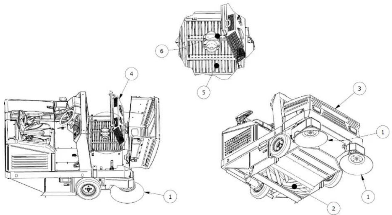
Technical diagram of a vehicle's internal components with numbered parts for identification.Figure 1
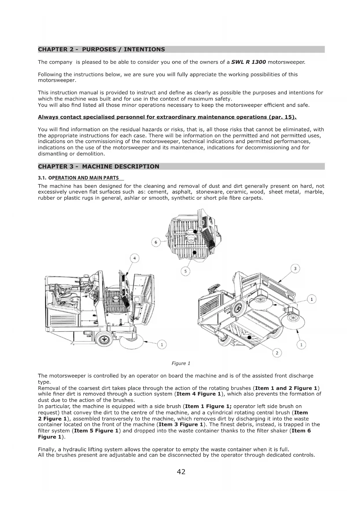
The motorsweeper is controlled by an operator on board the machine and is of the assisted front discharge type.
Removal of the coarsest dirt takes place through the action of the rotating brushes (Item 1 and 2 Figure 1) while finer dirt is removed through a suction system (Item 4 Figure 1), which also prevents the formation of dust due to the action of the brushes.
In particular, the machine is equipped with a side brush (Item 1 Figure 1; operator left side brush on request) that convey the dirt to the centre of the machine, and a cylindrical rotating central brush (Item 2 Figure 1), assembled transversely to the machine, which removes dirt by discharging it into the waste container located on the front of the machine (Item 3 Figure 1). The finest debris, instead, is trapped in the filter system (Item 5 Figure 1) and dropped into the waste container thanks to the filter shaker (Item 6 Figure 1).
Finally, a hydraulic lifting system allows the operator to empty the waste container when it is full. All the brushes present are adjustable and can be disconnected by the operator through dedicated controls.
3.2. SAFETY PROTECTIONS AND DEVICES
As shown in Figure 2, it is possible to see the safety protections and devices that must be intact and carefully fitted. The machine must not be used with damaged or missing protections or without safety devices that are not intact and functioning correctly. A description of the protections and safety devices is therefore provided below.

text_image
Technical diagram of a mechanical device with numbered components and exploded view, likely for assembly or maintenance purposes.Figure 2
| ITEM No. | DESCRIPTION |
| 1 Engine | hood |
| 2 Filter / | fan casing |
| 3 Seat | casing |
| 4 Machine | rear casing |
| 5 Machine | side casings |
| 6 Arm | protection flap |
| 7 | Man present safety micro;seat belt |
| 8 Side | brush casing |
| 9 Central | brush hatch |
| 10 Safety | Bar |
3.3. SIDE BRUSH
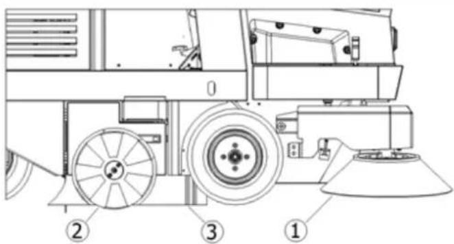
The side brush is installed on the operator side, Item 1 Figure 3, acts as a conveyor of dust and debris, and is designed primarily for the cleaning of edges, corners and profiles. It is possible to disengage each brush through a dedicated command. It is available in different hardness and nature of the bristles, depending on the type of material to be collected or the flooring.
On request, the additional side brush installed on the opposite side is installed.

IMPORTANT: Do not touch the side brush with your hands during rotation and do not collect filamentary materials (wires, ropes, etc.)
text_image
Technical diagram of a mechanical vehicle with numbered parts labeled 1, 2, and 3Figure 3
3.4. CENTRAL BRUSH
The central brush Item 2 Figure 3 is the main part of the machine and allows the loading of dust and debris into the waste container. It is available in different hardness and nature of the bristles, depending on the type of material to be collected or the flooring. It is adjustable in height when worn.

IMPORTANT: Do not collect cords, wires, packing straps, sticks, etc. longer than 25 cm because they could wrap around the central and side brush and then damage it.
3.5. DUST SEALS
The seals Item 3 Figure 3 surround the central brush and are very important for correct functioning of the machine as they allow dust to be suctioned in; it is important to check its condition often.
3.6. SUCTION SYSTEM
The suction system (Item 4 Figure 1) allows collection of the finest debris and prevents the formation of dust that can form by the action of the brushes.
3.7. FILTERING SYSTEM
The filtering system is obtained by means of a pocket filter Item 1 Figure 4 and traps the finest particles that are suctioned in by the suction system and prevents dust from spreading into the outside environment. A shaking system (Item 2 Figure 4) is used to release debris inside the waste container recleaning the filters.

text_image
Technical diagram of a mechanical device with labeled components, showing internal structure and numbered parts.Figure 4
3.8. WASTE CONTAINER
The waste container (Item 1, Figure 5) is used to contain all the material collected by the central brush and the dust of the filters. It is operated by a hydraulic actuator (Item 2, Figure 5) that allows it to be emptied and is equipped with a safety locking system (Item 3, Figure 5) in the fully open position.

text_image
Technical diagram of a mechanical device with numbered components and directional arrows indicating motion or assembly.Figure 5
3.9. CONTAINER FLAP
The container flap (Item 4 Figure 5) allows the operator to close the access of the debris to the waste container, preventing any leakage of the debris collected with the brushes stopped and during the lifting phase promoting emptying at the desired time and in the intended place (Figure 6). It is left open during cleaning operations. It is equipped with side seals and a central unit that has the task of promoting the action of the central brush during waste collection operations and ensuring a level of sealing that prevents the leakage of debris when closed.

natural_image
Technical line drawing of a mechanical device with multiple views and components, no visible text or symbolsFigure 6
| TECHNICAL CHARACTERISTICS U.o.M. SWL R 1300 | ||
| Power supply // Diesel | ||
| Engine power (KUBOTA D722-EF01) | kW/rpm | 14.7/3600 |
| Width central brush /Cleaning track mm 1000 x ∅330 | ||
| Width central brush + no. 1 right side brush (∅475) mm 1300 | ||
| Width central brush + no. 2 side brushes mm 1600 | ||
| Max advancement speed km/h 12 | ||
| Max. reverse speed Km/h 6 | ||
| Working speed | Km/h 8 | |
| Maximum cleaning capacity (with no. 2 side brushes) | sqm/h | 19200 |
| Maximum slope | % | 18 |
| Drive | // | rear |
| Transmission | // | Hydraulic |
| Minimum distance for reversing between two walls | mm 3400 | |
| Filtering surface (no. 1 pocket filter) | sqm | 8 |
| Container capacity | L | 490 |
| Maximum length with side brush | mm 2250 | |
| Maximum width | mm 1450 | |
| Standard version height | mm 1540 | |
| Weight ^4 | kg | 950 |
| Weight with cab (if applicable) ^5 | kg | 1140 |
| Weight with roll bar (if applicable) ^6 | kg | 1030 |
| Measured sound power level Lw ^☒ | dB | 89 |
| Guaranteed sound power level LwA | dB | 92 |
4.1. WORKPLACE POSITION
The workplace that must be occupied by the operator during use of the machine is only that shown in Figure 7. Depending on the equipment, the workplace can be protected by a roll bar (A, Figure 7, no side protection) or by a cab (B, Figure 7, side protection present). Access to the workplace is facilitated by a platform (1, Figure 7). In the case of cab protection, access to and leaving of the workplace takes place by opening/closing the door by means of the external/internal handle located in it (2, Figure 7).

Figure 7
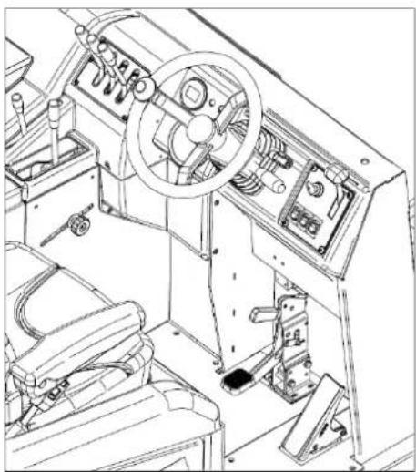
All the manual and pedal controls for use of the machine are located at the operator's seat, as shown in Figure 8.
natural_image
Technical line drawing of a ship's interior machinery showing steering wheel, dashboard, and control panel (no text or labels)Figure 8

IMPORTANT: For safety reasons, the machine switches off automatically if the operator gets up from the driving position.
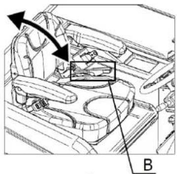
4.2. OPERATOR COMFORT
To ensure correct posture and the desired degree of comfort during use of the machine it is possible to adjust the stroke of the seat, the inclination of the backrest and the armrests through, respectively, lever A, lever B and wheel C, placed located each armrest, as shown in Figure 9.

natural_image
Technical line drawing of a car interior showing structural components and directional arrows (no text or symbols)
natural_image
Technical line drawing of a car interior showing structural components and a highlighted section (no text or symbols)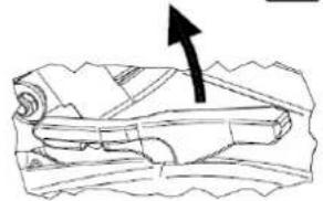
natural_image
Illustration of a rolled-up document with an arrow pointing upward (no text or symbols)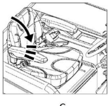
natural_image
Technical line drawing of a car interior showing steering wheel and dashboard (no text or symbols)
natural_image
Diagram of a boat hull with visible structural lines and directional arrows (no text or labels)Figure 9
It is also possible to adjust the inclination of the steering wheel, using the dedicated lever (Item 1 Figure 10).

text_image
Diagram of a vehicle's steering wheel and dashboard with labeled components and directional arrows indicating rotation or movement.Figure 10
For models equipped with a cab and roll bar only and to ensure the desired ventilation, it is also possible to open the rear window using the appropriate lever (Item 1 Figure 11). For models equipped with a cab, it is also possible to open the side window by using the dedicated handle (Item 2 Figure 11) and sliding it on the guides.

text_image
Technical diagram of a mechanical frame with labeled components 1 and 2Figure 11
4.3. CONTROL DEVICES
4.3.1. POSITION OF THE CONTROLS AND DESCRIPTION
As mentioned in para. 4.1, the control devices are located at the operator seat (Figure 8). Figure 12 displays the description and position of the operator controls and a detailed description below.

text_image
Technical diagram of a mechanical assembly with numbered components for identificationFigure 12
| 1 Starter key |
| 2 Engine regulator |
| 3 Accelerator |
| 4 Start and work lights selector |
| 5 Brake |
| 6 Parking Brake |
| 7 Brush movement selector |
| 8 Central brush control |
| 9 Central brush action regulator |
| 10 Side brush switch |
| 11 Side brush speed regulator |
| 12 Suction switch |
| 13 Filter shaker switch |
| 14 Waste container control |
| 15 Container flap control |
| 16 Indicator and hour meter |
| 17 Fuel level indicator |
4.3.2. STARTER KEY
Through the action on the key switch (Item 1 Figure 12) it is possible to start the engine and stop it (Figure 13). It is also possible to remove the key.
4.3.3. ENGINE REGULATOR
The engine regulator control (Item 2 Figure 12) consists of a lever through which it is possible to adjust the
intensity of the engine revolutions as shown in Figure 13.

text_image
ON OFF ST -Figure 13
4.3.4. ACCELERATOR PEDAL
The accelerator pedal (Item 3 Figure 12) is operated by pressing it and manages the motorsweeper. The direction of travel (forward or reverse) will be decided from the position set via the direction selector (Item 4 Figure 12).
4.3.5. START AND WORK LIGHTS SELECTOR

natural_image
Technical diagram of a mechanical component with directional arrows indicating motion or flow (no text or symbols present)Figure 14
The direction selector, with 6 combinations, (Item 4 Figure 12) is used to control the direction of travel of the motorsweeper (forward, backward and neutral) as shown in Figure 14. In the models where the work lights are included, the selector also controls the switching on and off by moving the lever up (lights on) or down (lights off).
4.3.6. BRAKE PEDAL
Pressing the brake pedal, (Item 5 Figure 12) it is possible to act on the braking system of the motorsweeper, stopping its operation.
This control is used to keep the motorsweeper braked when not in service and consists of a lever located immediately above the brake pedal (Item 6 Figure 12). Activation of the parking brake, with active electrical services, is accompanied by a continuous audible signal.
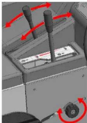
4.3.8. BRUSH MOVEMENT SELECTOR
The control lever (Item 7 Figure 12) allows the central brush and the side brush to be operated simultaneously or not. In the middle position (centre) both brushes remain inactive (Figure 15).
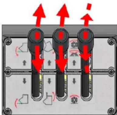
text_image
Diagram showing three vertical connectors with red arrows indicating directional movement, surrounded by mechanical components and motion indicators.Figure 15
4.3.9. CENTRAL BRUSH CONTROL
Through the control lever (Item 8 Figure 12) it is possible to raise or lower the central brush in order to ensure or not its cleaning action (Figure 16).
4.3.10. CENTRAL BRUSH ACTION REGULATOR
The central brush action regulator (Item 9 Figure 12) is represented by a slider along a slot that can be locked in place by rotating a threaded knob (Figure 16). It is used to adjust the height of the central brush from the floor when it is fully lowered (working position), adjusting the action on the surface to be cleaned.
natural_image
3D mechanical assembly diagram showing directional arrows and component placement (no text or symbols)Figure 16
4.3.11. SIDE BRUSH SWITCH
Pressing the selector button (Item 10 Figure 12) it is possible to configure the side brush in the working position (in contact with the surface to be cleaned) or at rest (in the raised position). Intermediate positions (Figure 17) are not possible.

flowchart
graph TD
    A["Top Panel"] --> B["Left Panel"]
    B --> C["Right Panel"]
    C --> D["Left Panel"]
    D --> E["Right Panel"]
    E --> F["Left Panel"]
Figure 17
4.3.12. SIDE BRUSH SPEED REGULATOR
Through the control lever (Item 11 Figure 12) the rotation speed of the side brush can be adjusted (Figure 15).
4.3.13. SUCTION SWITCH
Pressing the filter shaker switch button (Item 12 Figure 12) it is possible to operate and stop the suction system (Figure 17).
4.3.14. FILTER SHAKER SWITCH
Pressing the filter shaker button (Item 13 Figure 12) it is possible to operate the mechanism responsible for the falling of fine debris and dust trapped in the pocket filters. The switch is characterised by only one stable position (Figure 17).
4.3.15. WASTE CONTAINER CONTROL
Using the control lever (Item 14 Figure 12) the waste container ascent/descent device is activated. In the middle (centre) position the device is deactivated (Figure 15).
4.3.16. CONTAINER FLAP CONTROL
The control lever (Item 15 Figure 12) is used to open or close the flap of the waste container. In the middle position (centre) the flap is stopped (Figure 15).
4.3.17. INDICATOR AND HOUR METER
The indicator and hour meter (Item 16 Figure 12) includes all the operational and alarm indicators that can be activated during operation of the motorsweeper.

text_image
1 2 3 4 5 6 7 8 9Figure 18
In particular, as shown in Figure 18:
1: Work lights: ignition confirmation (in models where applicable)
2: Engine preheating: activation confirmation
3: Parking brake: activation confirmation
4: Container flap: closing position confirmation/alarm
5: Alternator 2 (electric motorsweeper services): fault alarm
6: Alternator 1 (engine): fault alarm
7: Engine cooling circuit: Engine water high temperature alarm/fault
8: Engine oil circuit: pressure loss alarm/fault
9: Hour meter
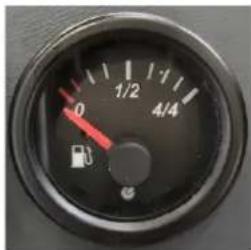
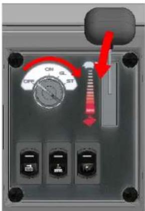
4.3.18. FUEL LEVEL INDICATOR
The fuel level indicator (Item 17 Figure 12) indicates the fuel level in the tank (Figure 19).
text_image
0 1/2 1/1 4/4Figure 19
4.3.19. POSITION AND DESCRIPTION OF CONTROLS FOR CAB AND ROLL BAR
The controls for the additional devices concerning the cab and roll bar are arranged on the top of the windscreen as shown in Figure 20 and refer to:
Cab ceiling light (A)
● Window washer device (B)
● Windscreen wiper (C)

natural_image
Technical line drawing of a mechanical frame assembly (no text or symbols)
text_image
A - B CFigure 20

text_image
B A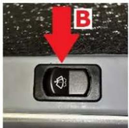
text_image
B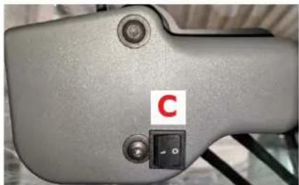
natural_image
Close-up of a gray mechanical device with a red label 'C' and a black control switch (no readable text or symbols beyond the label)Figure 21 Figure 22 Figure 23
The LED ceiling light in the cab is switched on or off via the pressure switch shown in Figure 21. Above the latter (Figure 21) is the stable position switch (Figure 22), which activates the window washer device. The device is activated when the switch is pressed and deactivated when it is released. The windscreen wiper is activated via the two-position stable switch (Figure 23). In position 1 the windscreen wiper is activated while in position 0 it is deactivated.
4.4. USE OF SAFETY PROTECTIONS AND DEVICES
4.4.1. WASTE CONTAINER SAFETY BAR POSITIONING
The safety bar (Item 10 Figure 2) prevents accidental closure of the waste container when it is lifted. After the container has been lifted, remove the safety bar from the rest position (Pos. 1 Figure 24) and place the safety bar in the base (Pos. 2 and 3, Figure 24). Remove the safety bar by lifting it from the base, sliding it along the slot and repositioning it in the initial position.

MAKE SURE THAT THE SAFETY BAR HAS BEEN DISCONNECTED BEFORE LOWERING THE WASTE CONTAINER.

text_image
1 2 3Figure 24
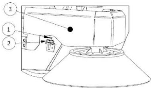
4.4.2. ENGINE HOOD, SEAT HOOD AND FILTER COVER SAFETY DEVICES
The engine hood (Item 1 Figure 2), the seat hood (Item 3 Figure 2) and filter covers (Item 2 Figure 2) can be easily opened to allow for inspection and maintenance operations. They are equipped with safety devices that prevent accidental closure. In particular, the engine hood and seat hood are equipped with safety rods that fit together as shown in Figure 25.

natural_image
Technical line drawing of a mechanical assembly with two views (top and side), showing internal components and structural details (no text or symbols)Figure 25
Opening beyond the limit of the filter cover is prevented by dedicated cables (Figure 26). This avoids the danger of damaging the cover itself as well as the persons around it.
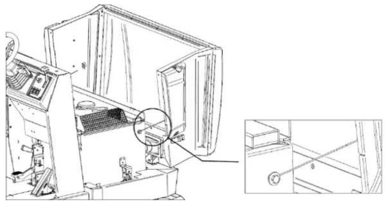
natural_image
Technical line drawing of an industrial machine interior with a magnified inset showing internal components (no text or symbols)Figure 26
CHAPTER 5 - PERMITTED AND NON-PERMITTED CONDITIONS OF USE
5.1. PERMITTED CONDITIONS OF USE
The motorsweeper was created to clean processing residues, dust, dirt in general, all flat, hard, not excessively uneven surfaces such as: cement, asphalt, stoneware, ceramic, wood, sheet metal, marble, rubber or plastic rugs in general, ashlar or smooth, synthetic or short pile fibre carpets.
The permitted conditions of use are as follows.
Minimum operating temperature: -20°C (-4°F)
Maximum operating temperature: +38°C (+100.4°F)
Maximum front and side slope: para. 3.10

ALWAYS USE SAFETY BELTS WHEN OPERATING THE MOTORSWEEPER.


Refer to the engine manual for additional permitted conditions of use.

IMPORTANT: Do not use and do not leave at rest with temperatures above +40°C (+104°F).

IMPORTANT: proceed with emptying, cleaning and maintenance of the machine only on flat and regular flooring that allows perfect stability to the machine for the entire duration of all the afore-mentioned operations.
5.2. NON-PERMITTED CONDITIONS OF USE
● The motorsweeper cannot be used on slopes greater than what is reported.
It cannot be used in environments where explosive or flammable materials are present.
It cannot be used on dirt, gravel or very uneven surfaces.
- It cannot collect oils, poisons and chemical materials in general, (in the case of having to use the machine in chemical plants request specific authorisation that will be produced by the retailer or parent company).
It cannot be used on urban or non-urban roads and must not travel on any public road.
- It cannot be used in poor lighting environments, except for models equipped with work lights.
It cannot be towed in any way including on private premises and on public roads or in public places.
It cannot be used to sweep snow or to wash or degrease surfaces in general that are wet or very wet.
- It cannot operate in the presence of spinning or the construction of filiform materials because the nature of the material to be collected is incompatible with the rotation of the brushes.
- It cannot be used in any way as a support for objects or as a raised floor for property and persons.
● Never let anyone approach within range of the machine.
- Do not make changes of any kind unless authorised by the manufacturer.


In addition, refer to the engine manual for any additional conditions of use that are not permitted.
CHAPTER 6 - PREPARATION (UNPACKING)
The motorsweeper is delivered packed on top of its pallet and comes with the side brush/brushes disassembled. After removing the outer packaging, the machine must be removed from the pallet:
By lifting with lifting devices of suitable capacity for the weight of the machine (indicated on the CE plate) using the eyebolts supplied (Figure 27);
Through the use of suitable platforms.
natural_image
Technical line drawing of a mechanical vehicle on a platform, showing front and side views with no visible text or symbols.Figure 27
At the end of the unpacking operation, disassemble and store the eyebolts and assemble the side brush/brushes, as illustrated in paragraph 14.5.

IMPORTANT: All waste materials resulting from the unpacking operation must be disposed of by the user, following the specific disposal regulations currently in force.

CHECK THAT THE PROTECTIONS ARE PERFECTLY INTACT AND CORRECTLY ASSEMBLED; IN CASE OF DEFECTS OR MISSING ELEMENTS DO NOT PROCEED WITH START-UP AND IMMEDIATELY CONTACT THE DEALER OR THE PARENT COMPANY.
CHAPTER 7 - COMMISSIONING


BEFORE PROCEEDING, IT IS NECESSARY TO HAVE READ ALL THE PREVIOUS CHAPTERS.
7.1. CHECKS BEFORE FIRST START-UP
The motorsweeper is supplied ready for the first start-up by the user. Adjustments, inspections and functional tests have already been performed by the Manufacturer.
Carefully check the hydraulic oil level in the dedicated tank (Figure 28).

natural_image
Technical line drawing of a mechanical device with internal components and a magnified inset showing a detail (no text or symbols)Figure 28


Read the engine instruction booklet carefully, but in any case:
1 - Check the engine oil level. If it is low top up.
2 - Check the water level in the radiator.
3 - Check the fuel level. If it is low top up.
All these operations must be carried out with the engine off and cold.
There is no need for specific training of the operator with regard to the first start-up of the motorsweeper, except for the information contained in this manual and, in that, relating to the engine.
7.3. FIRST START-UP
The first start-up of the motorsweeper is carried out in the same manner as described in paragraph 8.3.
CHAPTER 8 - USING THE MACHINE


BEFORE PROCEEDING, IT IS NECESSARY TO HAVE READ ALL THE PREVIOUS CHAPTERS.
8.1. CORRECT USE AND TIPS

ALWAYS USE SAFETY BELTS WHEN OPERATING THE MOTORSWEEPER.

NEVER TOUCH THE SIDE BRUSH WITH YOUR HANDS DURING ROTATION

CHECK THAT THERE ARE NO PERSONS LESS THAN 2 METERS FROM THE MOTORSWEEPER DURING THE WASTE CONTAINER EMPTYING OPERATIONS. ALSO CHECK THAT THERE IS ADEQUATE SPACE TO AVOID SHOCKS THAT COULD DAMAGE THE MOTORSWEEPER AND COMPROMISE ITS OPERATION (PARAGRAPH 10.3.2).

IMPORTANT: Before starting the work, check if on the surface there are any cords, plastic or metal wires or long rags, sticks, power wires etc.; these are dangerous and could damage the dust seals and brushes. They must therefore be removed before starting work with the machine.

IMPORTANT: For safety reasons, the machine switches off automatically if the operator gets up from the driving position. It can only be started when seated in the driver's seat.
- Be very careful when passing over rails or gate guides etc. These are the source of the greatest damage to the dust seals. When it is necessary to pass over them, do so very slowly.
- Disconnect the filter system when moving the machine over wet or very wet surfaces to avoid dampening and therefore deteriorating the filter. Avoid passing over puddles.
- If the surface to be cleaned is very dirty due to the quantity or quality of the material or dust to be collected, it is advisable to carry out a first "rough" sweep without paying too much attention to the result obtained. After this, with the waste container empty and the filters well shaken, repeat the steps; this will obtain the desired effect.
- The side brush must only be used for cleaning edges, profiles, corners, etc., it must be raised (disconnected) immediately afterwards in order to avoid raising unnecessary dust, and because the result obtained with the side brush inserted is always lower than that of the central brush only.
- For a good result, empty the container often and keep the filters clean by vibrating them by means of the filter shaker.
There is no need for special training of the operator with regard to the use of the motorsweeper, except for the information contained in this manual and, in that, relating to the engine.
8.3. OPERATIONAL START-UP
To start the machine:
Turn the starter key (Item 1 Figure 12) into the "ON" position, to the first click (Figure 29). The electric motorsweeper services are also activated;
Turn it again to the "GL" position, to the second click, to activate the preheating of the engine spark plugs. The relative light on the indicator (Item 16 Figure 12) is activated (no. 2 Figure 18).
Wait for the preheating light to turn off;
Turn the key to the "ST" position, to the third click. The engine begins to start;
When the engine is started, release the key that will return to the "GL" position.
After starting, gradually bring the throttle lever (Item 2 Figure 12) to the end of the stroke, allowing the engine to warm up for a few minutes.
Adjust the throttle lever to at least 12 ÷ 34 of the stroke for optimal performance.
text_image
ON OFF ST OFF OFF OFFFigure 29
8.4. FORWARD DIRECTION
To activate the forward direction:
Disengage the parking brake (Item 6 Figure 12), if activated (continuous beep).
Position the direction selector (Item 4 Figure 12) as shown in Figure 30.
Gradually press the accelerator pedal with your foot (Item 3 Figure 12). To reach the maximum travel speed, adjust the engine speed regulator lever (Item 2 Figure 12) to the end of the stroke (fully down) and press the forward pedal to the end of the stroke.
Release your foot to stop the traction of the engine and gradually press the brake pedal (Item 5 Figure 12) to finish operation of the motorsweeper.
Return the direction selector to the central (neutral) position as shown in Figure 30.
natural_image
Technical line drawing of a mechanical component with an arrow indicating direction (no text or symbols)
natural_image
Technical line drawing of a mechanical component with an arrow pointing to a specific feature (no text or symbols present)Figure 30
If necessary, activate the work lights by pulling the selector upwards (only in models where the work lights are included). When the lights are activated the relative indicator (no. 1 Figure 18) lights up on the indicator.
8.5. REVERSE DIRECTION
To activate reverse:
Disengage the parking brake (Item 6 Figure 12), if activated (continuous beep).
Position the direction selector back (Item 4 Figure 12) as shown in Figure 31.
Gradually press the accelerator pedal with your foot (Item 3 Figure 12). To reach the maximum travel speed, adjust the engine speed regulator lever (Item 2 Figure 12) to the end of the stroke (fully down) and press the forward pedal to the end of the stroke.
Release your foot to stop the traction of the engine and gradually press the brake pedal (Item 5 Figure 12) to end the reverse of the motorsweeper.
Return the direction selector to the central (neutral) position as shown in Figure 31.
natural_image
Technical line drawing of a mechanical assembly with no visible text or symbols
natural_image
Technical line drawing of a mechanical component with an arrow indicating direction (no text or symbols present)Figure 31
NOTE 1: The reverse speed is reduced by half with respect to the forward speed.
NOTE 2: An intermittent beep signals reversing of the motorsweeper.
8.6. OPERATIONAL SHUTDOWN
To stop the engine, bring the engine speed regulator lever (Item 2 Figure 12) to a minimum (fully up) and turn the starter key (Item 1 Figure 12) anti-clockwise until it reaches the "OFF" position.
In the event of prolonged stops, the parking brake must be engaged (Item 6 Figure 12) as described in paragraph 8.7.
NOTE: the braking system is also working with the machine switched off.

It is advisable to remove the key when the engine is switched off during maintenance, inspection and adjustment operations to prevent inadvertent or accidental ignition by persons unrelated to the operations
8.7. PARKING
In case of prolonged stops, in order to ensure the stability of the machine, it is necessary to activate the parking brake (Item 6 Figure 12) proceeding as follows (Figure 32):
Press the brake pedal (Item 5 Figure 12)
Move the parking brake lever (Item 6 Figure 12) downwards.

natural_image
Mechanical device with two black arrows indicating motion or force direction (no text or symbols)Figure 32
To disengage the parking brake, press the brake pedal (Item 5 Figure 12). The lever will return to the home position on its own.
NOTE: with the electrical services active, the parking brake is accompanied by a continuous audible signal.
8.8. EMERGENCY STOP
In case of emergency, it is necessary to:
turn the starter key (Item 1 Figure 12) anti-clockwise until it reaches the "OFF" position.
Engage the parking brake as described in paragraph 8.7.
8.9. CENTRAL BRUSH
To start the cleaning operations of the motorsweeper it is always necessary to insert the central brush.
With the engine running:
Use the brush movement selector lever (Item 7 Figure 12) bringing it to single configuration (only central brush activated, lever down) or combined (all brushes activated, lever up) as shown in Figure 33, pos. A.
Insert the central brush by pushing forward the brush control lever (Item 8 Figure 12) as shown in Figure 33, pos. B. The brush will lower and start cleaning.
Proceed with the forward movement of the motorsweeper (para. 8.4) to reach the areas to be cleaned.
To disengage the brush:
Pull back the brush control lever (Item 8 Figure 12) as shown in Figure 33, pos. C. The brush will rise from the surface.
Use the brush movement selector lever (Item 7 Figure 12) bringing it to a central configuration (brushes deactivated) as shown in Figure 33, pos. D.

Figure 33
8.10. SIDE BRUSH
To activate the side brush, with the engine running:
Use the brush movement selector lever (Item 7 Figure 12) bringing it to a combined configuration (all brushes activated, lever up) as shown in Figure 34, pos. A.
Insert the side brush using the side brush switch (Item 10 Figure 12) as shown in Figure 34, pos. B. The brush lowers to the surface.
If necessary, adjust the rotation speed through the adjustment lever (Item 11 Figure 12), moving it down to increase it and up to decrease it (Figure 34, pos. C).
To disengage the brush:
Disconnect the side brush using the side brush action selector (Item 10 Figure 12) as shown in Figure 34, pos.
D. The brush rises.
If necessary, decrease the rotation speed through the adjustment lever (Item 11 Figure 12) by moving it up
(Figure 34, pos. E).
Use the brush movement selector lever (Item 7 Figure 12) bringing it to the central position (all brushes deactivated) as shown in Figure 34, pos. F.

Figure 34
8.11. SUCTION
To activate or deactivate the suction, with the engine started or only with electrical services activated, turn the relative switch (Item 12 Figure 12, e Figure 35).

Figure 35
8.12. FILTER SHAKER
To activate the filter shaker, with the engine started or only the electrical services activated, turn the relative switch (Item 13 Figure 12) by pressing it in an unstable position for the desired time and releasing it to deactivate it (Figure 36).

Figure 36
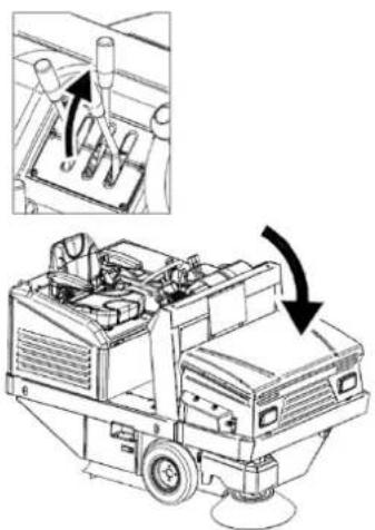
8.13. EMPTYING THE WASTE CONTAINER
To empty the waste container, with the engine running:
Close the container flap using the relative control lever (Item 15 Figure 12) as shown in box A in Figure 37. The light on the indicator (no. 4 Figure 18) comes on to confirm the operation.
Lift the waste container through the control lever (Item 14 Figure 12) lowering it and holding it in that position until the container reaches the desired position (B, Figure 37).
Open the container flap by raising the lever so that the waste is released where desired (C, Figure 37). The light on the indicator (no. 4 Figure 18) will turn off.

Figure 37
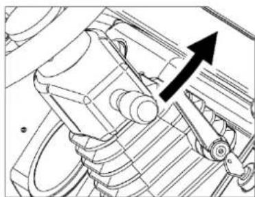
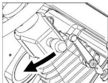
Once the emptying operation is completed, to return to the initial configuration, simply use the control lever of the container, lifting it (Figure 38). The container flap will be in the open position to start the cleaning operations.
natural_image
Technical line drawing of a mechanical device with an inset showing internal components and directional arrows (no text or symbols)Figure 38

IMPORTANT: Make sure that the flap is in the closed position when lifting the container and when moving without cleaning to avoid the unexpected spillage of waste. Also make sure that, during cleaning operations, it is in the open position, to allow the waste to enter the container.
CHAPTER 9 - ADJUSTMENTS


BEFORE PROCEEDING, IT IS NECESSARY TO HAVE READ ALL THE PREVIOUS CHAPTERS.
9.1. TRAINING OF OPERATORS
There is no need for specific training of the operator with regard to the various phases of adjustment of the motorsweeper, except for the information contained in this manual.
9.2. ADJUSTING THE CENTRAL BRUSH ACTION
When the central brush (Item 1 Figure 39) is worn and, consequently, begins to decrease its efficiency, adjust its height by means of the knob (Item 9 Figure 12) unscrewing and moving it forward, to lower the brush and increasing its action on the surface to be cleaned (2, Figure 39). Adjust until, in the lowered position, the brush leaves a streak of 3-5 cm on the floor (Figure 40). Once the desired degree of action has been achieved, tighten the knob to lock its position.
natural_image
Technical line drawing of a cleaning or dust removal machine with labeled components (no text or symbols present)Figure 39
To verify that the central brush is properly adjusted, its "track" must be measured as follows:
- After making the adjustments, activate the central brush and, without moving forward or backward, let it work at the same point for at least 10/15 seconds.
Lift the central brush and move the motorsweeper until the track that the central brush in rotation left is visible on the floor, as shown in Figure 40.

text_image
3-5 CM 100 CMFigure 40
9.3. SIDE BRUSH ACTION ADJUSTMENT

OPERATION TO BE PERFORMED WITH THE ENGINE OFF AND THE ELECTRICAL SERVICES DISABLED.
When the side brush is being used or to adjust its action on the surface:
Use the screw (Item 1 Figure 41) to adjust the height of the brush. The lower the screw, the lower the brush. When the desired height is reached, lock the position by tightening the ring nut (Item 2 Figure 41)
text_image
Technical diagram of a device with numbered components and directional arrows indicating flow or movementFigure 41
NOTE: If necessary, remove the side brush protection (Item 3 Figure 41) and reassemble it when the adjustment is complete.
CHAPTER 10 - SAFETY RULES
10.1. GENERAL RESIDUAL RISKS

DEFINITION: The residual risks that cannot be eliminated are all those that, for various reasons, cannot be removed, but for each of which we report the indications to operate in the context of maximum safety.
● Risk of injury to the hands, body and eyes if the machine is used without all the safety protections correctly fitted and intact.
- Risk of injury to the hands from touching the side brush or the central brush for any reason during rotation. The brushes can only be touched with the engine off and with the aid of protective gloves to avoid being pricked or cut if in the bristles there were pointed splinters of debris in general.
- Risk of inhalation of harmful substances, abrasions to the hands due to emptying of the waste container without using protective gloves and mask to protect the respiratory tract.
Risk of not being in control of the machine should it be used on slopes greater than those indicated in paragraphs 3.10 and 5.1, or of it not being properly stopped when left parked.
Risk of explosion or fire from refuelling with the engine on or with the engine off but not completely cold.
Risk of serious burns from performing any maintenance with the engine on or engine off but not completely cold.
Risk of inhalation of exhaust gas when used in an inadequately ventilated environment.
10.2. GENERAL RISKS FOR ACID BATTERIES
● Before charging, check that the room is well ventilated or charge in rooms that may be used for this purpose.
- Do not smoke, do not approach with naked flames, do not use grinding wheels and welders; in any case, do not cause sparks near the batteries.
- Do not draw power from the battery with pliers, sockets and temporary contacts.
Make sure that all connections (lugs, sockets, plugs, etc.) are always tight and in a good condition.
Do not place metal tools on the battery. - Keep the battery clean and dry using antistatic cloths if possible.
Top up with distilled water whenever the electrolyte level drops to 5 - 10 mm from the splashguard. - Avoid overcharging and keep the battery temperature below 45°C.
- Keep any centralised topping up systems in perfect working order, ensuring periodic maintenance is performed on them.
- Risk of electric shock and short circuit; for safety purposes, before carrying out any maintenance or repair on the battery (or on the machine), disconnect the +/- terminals from the battery poles.
- Risk of explosion during charging; this could occur when charging with an unsuitable battery charger (based on battery amps).
During the battery charging operation, or in any case when the battery charger plug is inserted, it is forbidden to turn on the machine or to move it (even manually).
In the event of accidental spills of liquid from the batteries due to any reason, mop up leaks with absorbent material using anti-acid gloves and clothing, safety glasses and respiratory protection devices, consulting the battery manual.
10.3. PROTECTIVE MEASURES
10.3.1. PERSONAL PROTECTION EQUIPMENT (PPE)
In addition to what is reported in the previous paragraphs, in order to proceed safely during maintenance, adjustment, inspection and cleaning of the motorsweeper, personal protection equipment (PPE) suitable for the type of risk that may occur will be necessary.
In particular, for the maintenance operations referred to in this manual, the following will be necessary:
● Safety gloves against mechanical risk;
- Safety glasses;
● Respiratory protective devices.
In case of accidental acid spills from the battery or if hazardous material has been accidentally collected, the following will be necessary:
● Safety gloves against mechanical and chemical risks (e.g. neoprene gloves);
● Safety glasses;
- FFP3 or higher face mask;
● Protective clothing against chemical risk.
For the cleaning operations of the motorsweeper it will also be necessary to use only suitable work clothes and ensure they are cleaned at the end of the work.


Refer to the engine manual for further prevention and protection measures.
10.3.2. PROTECTIVE MEASURES FOR THE WASTE CONTAINER EMPTYING OPERATION
During the waste container emptying operations it will be necessary to respect the appropriate safety distances depending on the dimensions of the same (Figure 42).

text_image
700 2700 1330Figure 42

CHECK THAT THERE ARE NO PERSONS LESS THAN 2 METERS FROM THE MOTORSWEEPER DURING THE WASTE CONTAINER EMPTYING OPERATIONS. ALSO CHECK THAT THERE IS ADEQUATE SPACE TO AVOID SHOCKS THAT COULD DAMAGE THE MOTORSWEEPER AND COMPROMISE ITS OPERATION.

ALWAYS INSTALL THE PROTECTION BAR AS SHOWN IN PARAGRAPH 4.4.1. TO PREVENT ACCIDENTAL CLOSURE OF THE WASTE CONTAINER WHEN IT IS BEING LIFTED.
CHAPTER 11 - STABILITY OF THE MACHINE
11.1. STABILITY DURING USE
The stability of the machine during travel and cleaning operations is mainly guaranteed by compliance with the maximum slope values (para. 3.10 and 5.1) as well as by verification of the capacity of the work surface which must be such as to withstand the value of the weight of the motorsweeper indicated on the CE plate.
The operation of emptying of the waste container, and all the maintenance, adjustment, cleaning and inspection phases must take place on floors without slopes and such as to bear the value of the weight of the motorsweeper indicated on the CE plate.
To ensure the necessary stability during machine parking, it will be necessary to insert the parking brake as shown in para. 8.7. If it is not possible to leave the machine stationary on flat surfaces, it is advisable to use dedicated wheel stop wedges.
The stability of the raised waste container for inspection, cleaning and maintenance operations is guaranteed by positioning the safety bar as described in para. 4.4.1.
11.2. STABILITY DURING TRANSPORTATION
The motorsweeper must be transported and handled considering the weight of the motorsweeper indicated on the CE plate.
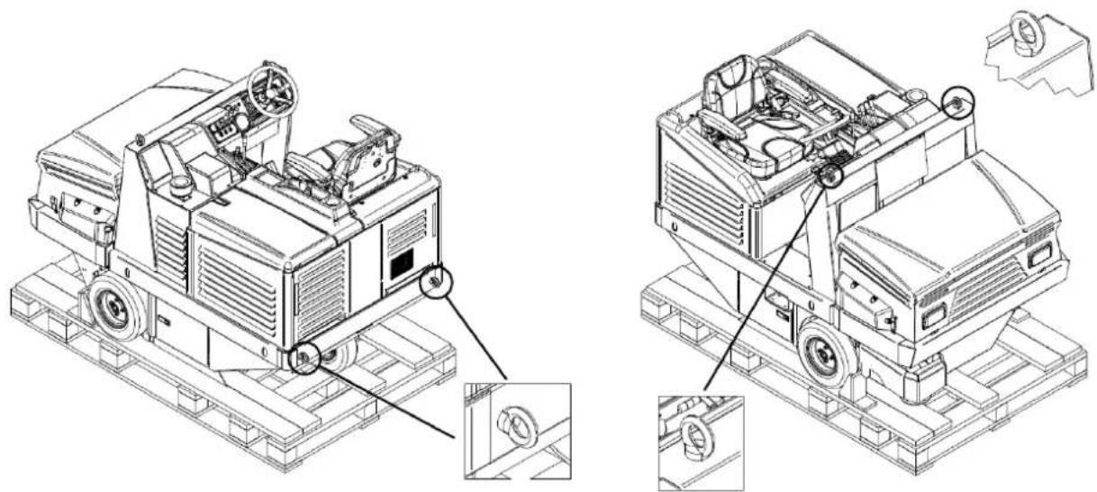
Lifting of the motorsweeper must take place as shown in para. 6 while for transportation it will be necessary to secure the machine. For this purpose, it is possible to use the relative fastening slots (Figure 43). Once positioned, it is necessary to insert the parking brake as shown in para. 8.7 using, where appropriate and in addition, dedicated wheel stop wedges.

natural_image
Technical line drawing of a mechanical device with labeled parts (no readable text or symbols)Figure 43
CHAPTER 12 - TRANSPORTATION, HANDLING AND DECOMMISSIONING
12.1. DECOMMISSIONING

OPERATION TO BE PERFORMED WITH THE ENGINE OFF AND COLD.
The motorsweeper must be decommissioned in accordance with the following points:
- Remove the battery from its housing and store it in a dry and well-ventilated place. For a good life of the unused battery, it is necessary to charge and possibly top up with distilled water every 30/40 days (acid batteries).
- Clean the dust filters and the waste container.
- Close the fuel tank valve.


Refer to the engine manual for further information for engine decommissioning.
12.2. PACKAGING, LIFTING AND TRANSPORTATION
In the event that the machine needs to be packed, it will be necessary to proceed with disassembly of the side brush/brushes as described in paragraph 14.5
Then lift the motorsweeper by placing it on the appropriate pallet using the necessary lifting devices, adapted to the weight of the motorsweeper shown on the plate, or ascent platforms. For lifting use the eyebolts (para. 6 Figure 27).
Observe what is indicated in the paragraph 6 regarding lifting of the machine, and in the paragraph 11.2 regarding its transportation.
CHAPTER 13 - EMERGENCY SITUATIONS
13.1. EMERGENCY SITUATIONS
In any emergency situation, the following may occur:
- inadvertently passing with the machine in motion over current cables on the floor, which then became twisted to the central or side brush,
● unusual noise is heard coming from inside the machine or engine,
● incandescent materials or flammable liquids, chemical materials in general, poisons, etc.
the following are necessary:
If the engine is switched on, proceed to the emergency stop as described in paragraph 8.8.
Proceed to insert the parking brake as described in paragraph 8.7
Move away from the machine
Immediately call for help if other persons are involved.


Refer to the engine manual for further information on emergency procedures.
13.2. STARTING AFTER AN EMERGENCY SITUATION
Before proceeding to use the machine after an emergency situation has been resolved, an inspection of all the parts of the machine must be carried out (para. 3), with particular reference to the protections and safety devices.
It is only possible to resume normal use of the motorsweeper after these checks have been successful (all parts working and intact).
There are no rearming procedures.


Refer to the engine manual for further information for starting of the engine after an emergency situation.
CHAPTER 14 - MAINTENANCE
14.1. GENERAL SAFETY RULES


BEFORE PROCEEDING, IT IS NECESSARY TO HAVE READ ALL THE PREVIOUS CHAPTERS.

ALL MAINTENANCE AND CLEANING OPERATIONS MUST BE CARRIED OUT WITH THE KEY DISCONNECTED AND THE ENGINE OFF AND COLD.

NEVER TOUCH THE BRUSHES WITH YOUR HANDS DURING ROTATION

CHECK THAT THERE ARE NO PERSONS UNRELATED TO THE CLEANING AND MAINTENANCE OPERATIONS LESS THAN 2 METERS FROM THE MOTORSWEEPER DURING THEIR ENTIRE DURATION.

TAKE THE NECESSARY MEASURES TO AVOID ACCIDENTAL AND INVOLUNTARY STARTING DURING ALL PHASES WHERE IT IS EXPECTED TO OPERATE WITH THE ENGINE OFF AND THE ELECTRICAL SERVICES DISCONNECTED.
There is no need for specific training of the operator with regard to the maintenance and cleaning of the motorsweeper, except for the information contained in this manual and, in that, relating to the engine.
14.3. DUST SEALS

OPERATION TO BE PERFORMED WITH THE ENGINE OFF AND COLD WITH GLOVES, SAFETY GOGGLES AND RESPIRATORY PROTECTION DEVICES.
Every 70/100 hours of work, check the condition of the dust seals Item 1-7 Figure 44 and replace if necessary.
To replace the dust seals:
Loosen the screws of the seal fixing plate Item 1-7 Figure 44;
Remove the worn seal and replace it with a new one;
Retighten the screws of the seal fixing plate Item 1-7 Figure 44.

text_image
Technical diagram of a vehicle suspension system with numbered components labeled 1 to 4
text_image
Technical diagram of a mechanical device with numbered components labeled 5, 6, and 7Figure 44
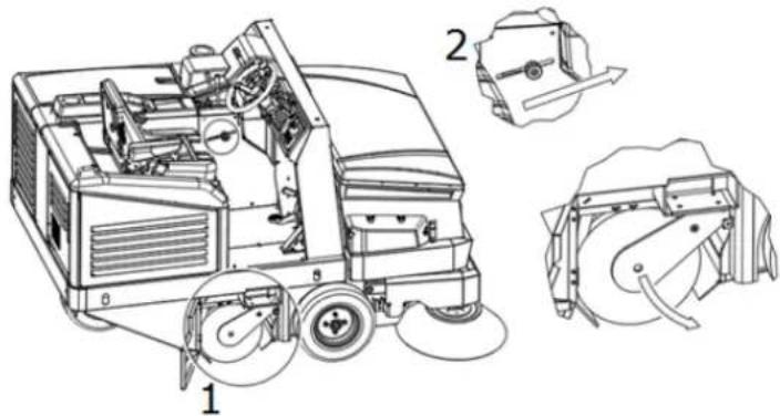
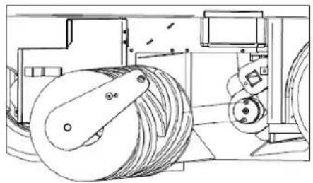
14.4. CENTRAL BRUSH

OPERATION TO BE PERFORMED WITH THE ENGINE OFF AND COLD WITH GLOVES, SAFETY GOGGLES AND RESPIRATORY PROTECTION DEVICES. ONLY PROCEED WITH THE INSPECTION AFTER INSERTING THE SAFETY BAR (PARA. 4.4.1).
Every 50/80 hours of work or when required, check the good condition of the central brush (Item 2 Figure 3 para.3.4), in particular if it is assumed that it has inadvertently collected cords, wires, etc.
To proceed with the inspection of the central brush:
- lift the waste container and then turn off the engine and electrical services. install the safety bar (para. 4.4.1) proceed with the inspection.

text_image
Technical diagram of a mechanical device with numbered components for identificationFigure 45
If it is necessary to replace the central brush: Open the right side hatch (Item 1 Figure 45) Disassemble the right flap stop (Item 2 Figure 45) Move the flap (Item 3 Figure 45) Remove the screw (Item 4 Figure 45) Remove the support arm (Item 5 Figure 45) Remove the old brush (Item 6 Figure 45)
To complete the assembly, perform the operations described in reverse, being sure to respect the brush interconnections during reassembly (Figure 46).
Adjust the height of the new brush as described in paragraph 9.2.
natural_image
Technical line drawing of a mechanical device with rollers and gears (no text or symbols)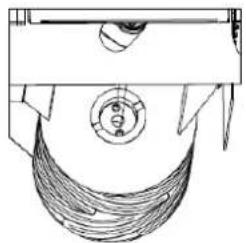
natural_image
Technical line drawing of a mechanical component with no visible text or symbols
natural_image
Technical line drawing of a mechanical component with helical grooves and a cylindrical shaft (no text or symbols)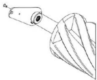
natural_image
Technical line drawing of a mechanical component with a cylindrical shaft and flanged base (no text or symbols)Figure 46

MAKE SURE THAT THE SAFETY BAR HAS BEEN DISCONNECTED BEFORE LOWERING THE WASTE CONTAINER.
14.5. SIDE BRUSH

OPERATION TO BE PERFORMED WITH THE ENGINE OFF AND COLD WITH GLOVES, SAFETY GOGGLES AND RESPIRATORY PROTECTION DEVICES.
Every 50/80 hours of work or when required, check the good condition of the side brush (Item 1 Figure 3 para.3.3), in particular if it is assumed that it has inadvertently collected cords, wires, etc.
In the event that its replacement is necessary:
Raise the side brush (para. 8.10)
Unscrew the ring nut Item 1 Figure 47 to detach the side brush Item 2 Figure 47 from the plastic flange Replace the worn brush with the new one, inserting it on the flange and tightening the ring nut to lock it, adjusting the height as described in para. 9.3

text_image
Technical diagram of a mechanical device with labeled parts, showing assembly and component details.Figure 47


Refer to the engine manual for further information on engine maintenance and related safety measures to be taken during operation.
Read the engine manual carefully, and:
1) Check the engine oil level every 20 hours of machine operation;
2) The first change of engine oil must take place after 50 hours of operation, add the quantity indicated in the engine manual; the recommended oil for temperate climates is 10W-30 multi-grade for petrol and diesel engines. When operating in areas with a non-temperate climate, identify the appropriate type of oil from the engine instruction manual. Use the dedicated drain to change the oil positioned under the engine sump.
3) Change the oil after every 90/100 hours of operation.
4) Clean the air filter every 25 operating hours, or earlier if necessary, and replace as necessary (see engine instruction manual).

TO CHECK OR REPLACE THE ENGINE OIL IT IS NECESSARY TO WEAR SAFETY GLOVES TO PROTECT AGAINST CHEMICAL AGENTS, POSSIBLY MADE OF NITRILE RUBBER. DO NOT DISPOSE OF USED OIL AS HOUSEHOLD WASTE AS IT IS HIGHLY POLLUTING. DISPOSE OF USED OIL IN ACCORDANCE WITH THE PROVISIONS OF THE LAW.
14.7. SPECIFIC MAINTENANCE FOR ACID BATTERIES

FOLLOW THE RULES AND PRECAUTIONS PROVIDED IN 10.2. ALWAYS WEAR SAFETY GLASSES AND ANTI-ACID GLOVES AND CLOTHING.
- For a good life of the batteries, whether they are flat or tubular, never discharge them completely. FULLY DISCHARGED BATTERIES (EVEN NEW ONES) ARE NO LONGER RECHARGEABLE.
- Check often the level of solution of the battery and if necessary add only distilled water.
- Always carry out the charging cycle without interruption.
- DISPOSE OF USED BATTERIES FOLLOWING THE REGULATIONS IN FORCE.


Consult the documentation provided by the Battery Manufacturer for further information on their maintenance and related safety measures to be adopted during the operation.
14.8. CLEANING THE MACHINE
Clean the external parts of the machine using damp cloths or soft brushes.

OPERATION TO BE PERFORMED WITH THE ENGINE OFF AND COLD WITH GLOVES, SAFETY GOGGLES AND RESPIRATORY PROTECTION DEVICES.

CLEANING OF ALL EXTERNAL PARTS OF THE MACHINE BY DIRECT WATER JET IS NOT PERMITTED.

DO NOT USE DETERGENTS OR CHEMICALS IN GENERAL THAT ARE TOO AGGRESSIVE, ABRASIVE POWDERS OR SIMILAR TO CLEAN THE CONTROL PANEL AND WHERE THERE ARE LABELS OR PRINTED PARTS IN GENERAL TO AVOID DAMAGING THEM, MAKING THEM INCOMPREHENSIBLE AND ILLEGIBLE.

OPERATION TO BE PERFORMED WITH THE ENGINE OFF AND COLD WITH GLOVES, SAFETY GOGGLES AND RESPIRATORY PROTECTION DEVICES.
Every 200/300 hours of work, or when required, check the dust filter (Item 1 para. 3.7). For deep cleaning, it must be removed from its seat, as follows:
Open the filter cover Item 1 Figure 48;
disconnect the pins of the suction motors Item 2 Figure 48;
lift the support of the suction motors Item 3 Figure 48;
disassemble the vibrator cage Item 4 Figure 48;
disassemble the filter frame Item 5 Figure 48;
disassemble the filter Item 6 Figure 48.
lift the filter with a forklift truck, making sure that the internal measurement of the brackets is integral with the filter measurement (adjust the brackets to the correct distance between each other and lock them in place) or do so manually, with a minimum number of 2 persons. Then, keep it lifted from the ground with the aid of a forklift truck.
To clean it, first shake it (not violently), then, to clean it thoroughly, with an air gun or similar blow from the outside inside, as illustrated in Item 7 Figure 48. When reassembling, make sure that the black seal is always well supported and centred.
At the end of the cleaning proceed to reassemble the filter by performing the operations described in reverse.
Make sure that the filter is always in a good condition and replace it if necessary.

text_image
Technical diagram of an industrial machine with seven labeled components, showing exploded and assembled views.Figure 48
14.10. CLEANING THE WASTE CONTAINER

OPERATION TO BE PERFORMED WITH THE ENGINE OFF AND COLD WITH GLOVES, SAFETY GOGGLES AND RESPIRATORY PROTECTION DEVICES. MAKE SURE THAT ACCESS TO PERSONS NOT INVOLVED IN THE OPERATIONS IS DENIED.
Every 200/300 hours of work, or when required, clean the waste container. It is advisable to perform this operation when cleaning the filters (para. 14.9).
Proceed as follows:
Lower the waste container and open the flap. Then stop the motorsweeper (para. 8.6)
Remove the filters as described in paragraph 14.9.
Remove any waste in the container.
Once the operation is completed, proceed to reassemble the filters as described in paragraph 14.9.

IMPORTANT: It is highly recommended to clean the filter container without the use of water or to allow the motorsweeper to dry completely before resuming cleaning operations.
CHAPTER 15 - EXTRAORDINARY MAINTENANCE

EXTRAORDINARY MAINTENANCE ARE ALL OPERATIONS THAT HAVE NOT BEEN MENTIONED IN THIS BOOKLET; THEY MUST THEREFORE BE CARRIED OUT BY SPECIALIST ASSISTANCE PERSONNEL, APPOINTED FOR THIS PURPOSE (SEE BOOKLET COVER).
CHAPTER 16 - SPARE PARTS
For the replacement of machine parts, refer to the list of spare parts provided by the Manufacturer.
CHAPTER 17 - DISMANTLING AND DEMOLITION

DISMANTLING OR DEMOLITION MUST BE CARRIED OUT BY THE CUSTOMER, IN FULL COMPLIANCE WITH THE REGULATIONS IN FORCE ON THE MATTER, CONFERRING THE ENTIRE MACHINE OR THE PARTS THAT COMPOSE IT TO COMPANIES ASSIGNED TO SUCH SERVICES.
CHAPTER 18 - DEFECTS / CAUSES / SOLUTIONS
There are two fundamental defects:
● the machine creates dust during use,
● the machine leaves dirt on the ground.
There can be many causes, but with careful use and good routine maintenance they will not occur. The most common and frequent problems that can occur are listed in the following table.
| DEFECTS CAUSES SOLUTIONS | ||
| The machine creates dust. | Suction closed. Activate the suction (para. 8.11) | |
| Filter clogged. | Clean it, "shake" it with the appropriate tools and if necessary remove it and clean it thoroughly. | |
| Damaged filter Replace it. | ||
| Filter inserted incorrectly. | Fit it with the appropriate seal and make sure that it is well inserted and tightly in place with the appropriate fasteners. | |
| Continuous use of the side brush. | Use the side brush only for the cleaning of edges, profiles and corners. | |
| Damaged side seals. Adjust or replace them. | ||
| The machine leaves dirt on the ground. | The central brush is not adjusted properly or it has worn out. | Adjust the central brush, checking the "track". |
| You have picked up wires, cords, etc. | Remove them. | |
| Damaged side seals. Replace them. | ||
| Collection drawer full. Empty it. | ||
| The Diesel engine doesn't work to the best of its ability. | Dirty engine air filter. | Clean or replace it (see engine maintenance manual) |
| Dirty fuel filter cartridge. | Replace it (see engine maintenance manual) | |
| The engine does not start or tends to shut down | The seat safety switches - protections are not closed properly or do not work. | Close tightly or replace the switch. |
| Battery discharged (battery LED light does not turn on at the first click of the starter key) | Replace/charge the battery. | |
| The alternator does not charge the battery (battery LED light on while the engine is running; no. 5, 6, Figure 18, para. 4.3.17) | Replace/repair the alternator (see engine maintenance manual) | |
| Check the engine oil level, it must always be at the maximum level | Top up with oil (see engine maintenance manual) | |
| Check for fuel | Refuel | |
CHAPTER 19 - WARRANTY
This machine is guaranteed against manufacturing or assembly defects for 12 months from the date of sale. The warranty includes only and exclusively the replacement or repair of parts that are found to be defective. Any other requests will not be accepted.
Damage due to normal wear and tear, use other than that reported in this manual, damage caused by incorrect adjustments, technical interventions not performed correctly and acts of vandalism are not included.
index....pag.
CHAPITRE 1 - RÈGLES GÉNÉRALES ..... 75
CHAPITRE 2 - BUTS/INTENTIONS ...... 76
CHAPITRE 3 - DESCRIPTION DE LA MACHINE ..... 76
CHAPITRE 4 - POSTE DE TRAVAIL ET COMMANDES ....81
CHAPITRE 5 - CONDITIONS D'UTILISATION AUTORISÉES ET NON AUTORISÉES ..... 89
CHAPITRE 6 - PRÉPARATION (DÉBALLAGE)....90
CHAPITRE 7 - MISE EN SERVICE ..... 91
CHAPITRE 8 - UTILISATION DE LA MACHINE....91
CHAPITRE 9 - RÉGLAGES 96
CHAPITRE 10 - NORMES DE SÉCURITÉ....98
CHAPITRE 11 - STABILITÉ DE LA MACHINE ..... 99
CHAPITRE 12 - TRANSPORT, MANUTENTION ET MISE HORS SERVICE ..... 100
CHAPITRE 13 - SITUATIONS D'URGENCE .... 100
CHAPITRE 14 - ENTRETIEN .... 101
CHAPITRE 15 - ENTRETIEN EXTRAORDINAIRE.... 106
CHAPITRE 16 - PIÈCES DE RECHANGE ..... 106
CHAPITRE 17 - DÉMANTÈLEMENT ET DÉMOLITION. 106
CHAPITRE 18 - DÉFAUTS/CAUSES/SOLUTIONS ..... 106
CHAPITRE 19 - GARANTIE....107
LÉGENDE
AVANT D'UTILISER LA MACHINE, LIRE ATTENTIVEMENT CE MANUEL D'INSTRUCTIONS.
LA SOCIÉTÉ DÉCLINE TOUTE RESPONSABILITÉ POUR LES DOMMAGES AUX CHoses ET/OU AUX PERSONNES RÉSULTANT DU NON-RESPECT DES NORMES ÉNUMÉRÉES DANS CE MANUEL OU D'UNE UTILISATION IRRÉGULIÈRE ET/OU INAPPROPRIÉE DE LA MACHINE.
LA MACHINE N'EST PAS DESTINÉE À ÊTRE UTILISÉE PAR DES PERSONNES (ENFANTS INCLUS) AYANT DES CAPACITÉS PHYSIQUES, SENSORIELLES ET PSYCHIQUES RÉDUITES OU QUI N'ONT PAS PLEINEMENT APPRIS ET COMPRIS TOUS LES CONTENUS DE CE MANUEL.
L'UTILISATION DE LA MACHINE DOIT ÊTRE SURVEILLÉE POUR ÉVITER SON UTILISATION PAR LES ENFANTS.
LA MACHINE A ÉTÉ CONÇUE POUR UNE UTILISATION COMMERCIALE, PAR EXEMPLE DANS LES HÔTELS, LES HÔPITAUX, LES COMMERCES, LES MAGASINS, LES BUREAUX, LES LOCAUX LOUÉS ET LES GRANDS ESPACES EN GÉNÉRAL.
EN OUTRE, LA MACHINE :
- NE DOIT PAS ÊTRE UTILISÉE OU TENUE À L'EXTÉRIEUR DANS DES CONDITIONS HUMIDES OU EXPOSÉE DIRECTEMENT À LA PLUIE ;
• DOIT ÊTRE STOCKÉE OBLIGATOIREMENT SOUS ABRI.
TOUS LES OUTILS NÉCESSAIRES À LA PROTECTION PERSONNELLE (GANTS, MASQUES, LUNETTES, VERRES BLANCS, CLÉS ET OUTILS) SERONT FOURNIS PAR L'UTILISATEUR.
POUR PLUS DE COMMODITÉ, CONSULTER L'INDEX DES SUJETS.
POUR TOUTE AUTRE CONSULTATION, TOUJOURS GARDER CE MANUEL AVEC SOI (EN CAS DE PERTE, DEMANDER IMMÉDIATEMENT UNE COPIE À VOTRE REVENDEUR).
LA SOCIÉTÉ SE RÉSERVE LE DROIT D'APPORTER DES MODIFICATIONS OU DES PERFECTIONNEMENTS AUX MACHINES DE SA PROPRE PRODUCTION, SANS OBLIGATION DE SA PART D'EN FAIRE BÉNÉFICIER LES MACHINES PRÉCÉDEMENT VENDUES.
TOUTES LES MOTOBALAYEUSES SONT CONFORMES AUX DIRECTIVES DE L'UE ET SONT ÉTIQUETÉES :

text_image
EAC CE Made in Italy Type S/N Code Year / Week Weight Kg KW PO n. Volts LwA dB 2 %CHAPITRE 2 - BUTS/INTENTIONS
text_image
Technical diagram of a mechanical device with numbered parts for identification and assembly reference.Figure 1
text_image
Technical diagram of a cleaning or dust removal machine with numbered components for identification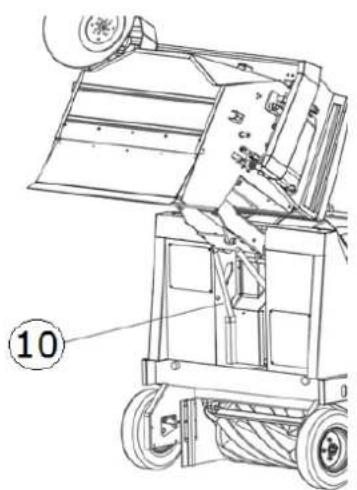
natural_image
Technical line drawing of a mechanical device with wheels and a labeled component (no text or symbols beyond label)Figure 2
text_image
Technical diagram of a truck with numbered parts labeled ①, ②, and ③ for identification.Figure 3
3.4. BROSSE CENTRALE
natural_image
Technical line drawing of a mechanical device with labeled components (no text or symbols present)Figure 4
3.8. CONTENEUR DE DÉCHETS
text_image
Technical diagram of a mechanical device with numbered components and directional arrows indicating motion or assembly.Figure 5
3.9. FLAP CONTENEUR
natural_image
Line drawing of a mechanical lift or lift jack system with no visible text or symbols
natural_image
Pure technical line drawing of a mechanical component with no text or symbols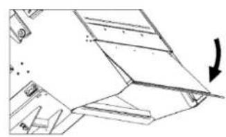
natural_image
Technical line drawing of a mechanical component with an arrow indicating direction (no text or symbols)Figure 6
3.10. DONNÉES TECHNIQUES
natural_image
Technical line drawing of a ship's interior and steering wheel (no text or symbols)Figure 8

natural_image
Technical line drawing of a car interior showing structural components and directional arrows (no text or symbols)

natural_image
Technical line drawing of a car interior showing structural components and a zoomed-in section (no text or symbols)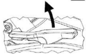
natural_image
Illustration of a rolled-up document with an arrow pointing upward (no text or symbols)
natural_image
Technical line drawing of a car interior showing structural components and airflow direction (no text or symbols)
natural_image
Diagram of a boat hull with directional arrows indicating flow or movement (no text or labels)Figure 9
text_image
Diagram of a ship's steering wheel and control panel with directional arrows indicating rotation or movementFigure 10
text_image
Technical diagram of a mechanical frame with labeled components 1 and 2, showing internal structure and assembly details.Figure 11
4.3. DISPOSITIFS DE COMMANDE
4.3.1. POSITION DES COMMANDES ET DESCRIPTION
text_image
Technical diagram of a mechanical device with numbered components for identificationFigure 12
natural_image
Technical diagram of a vehicle's internal components with directional arrows indicating movement (no text or labels)Figure 14
text_image
Diagram showing three vertical cylindrical components with red arrows indicating direction, possibly illustrating a mechanical or electrical component assembly.Figure 15
4.3.9. COMMANDE BROSSE CENTRALE
natural_image
3D mechanical assembly diagram showing lever mechanism with red arrows indicating motion (no text or symbols)Figure 16
4.3.11. INTERRUPTEUR BROSSE LATÉRALE
natural_image
Technical line drawing of a mechanical frame or support structure (no text or symbols)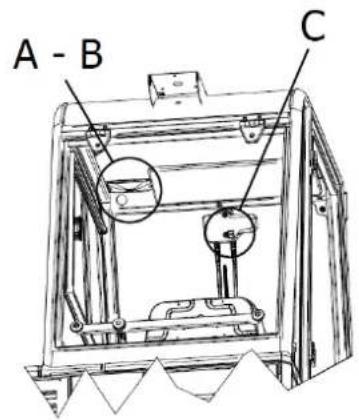
text_image
A - B CFigure 20

text_image
B A
text_image
B
natural_image
Close-up of a gray mechanical component with a red label 'C' and a black control switch (no readable text or symbols beyond the label)Figure 21 Figure 22 Figure 23
natural_image
Technical line drawing of a mechanical assembly with two views (top and side), showing internal components and structural details (no text or symbols)Figure 25
natural_image
Technical line drawing of an industrial machine interior with a magnified inset showing internal components (no text or symbols)Figure 26
CHAPITRE 5 - CONDITIONS D'UTILISATION AUTORISÉES ET NON AUTORISÉES
5.1. CONDITIONS D'UTILISATION AUTORISÉES
natural_image
Technical line drawing of a mechanical device on a pallet, showing internal components and a close-up inset (no text or symbols)
natural_image
Technical line drawing of a mechanical device with internal components and mounting base (no text or symbols)Figure 27
natural_image
Technical line drawing of a mechanical device with internal components and a magnified inset showing a component detail (no text or symbols present)Figure 28


natural_image
Technical line drawing of a mechanical component with an arrow indicating direction (no text or symbols present)
natural_image
Technical diagram of a mechanical component with a black arrow pointing to a specific feature (no text or symbols present)Figure 30
natural_image
Technical line drawing of a mechanical component with a black arrow indicating direction (no text or symbols present)
natural_image
Technical line drawing of a mechanical component with no visible text or symbolsFigure 31
natural_image
Mechanical device diagram showing a lever mechanism with two arrows indicating motion (no text or symbols present)Figure 32
natural_image
Technical line drawing of a mechanical device with no visible text or symbols
natural_image
Technical line drawing of a mechanical device with gears and a directional arrow indicating motion (no text or symbols)
natural_image
Technical line drawing of a mechanical device with wheels and a directional arrow indicating motion (no text or symbols)Figure 37
natural_image
Technical line drawing of a mechanical device with an inset showing a tool interacting with a component (no text or symbols present)Figure 38

text_image
Technical diagram of a mechanical device with labeled parts, showing exploded and assembled viewsFigure 39
text_image
Technical diagram of a device with numbered components and directional arrows indicating movement or flow.Figure 41
natural_image
Technical line drawing of a mechanical device with labeled parts and components (no readable text or symbols)Figure 43
CHAPITRE 12 - TRANSPORT, MANUTENTION ET MISE HORS SERVICE
12.1. MISE HORS SERVICE

OPÉRATION À EFFECTUER MOTEUR ÉTEINT ET FROID.
13.1. SITUATIONS D'URGENCE
text_image
Technical diagram of a mechanical assembly with numbered components labeled 1 to 4
text_image
Technical diagram of a machine with numbered components labeled 5, 6, and 7Figure 44
14.4. BROSSE CENTRALE

OPÉRATION À EFFECTUER À MOTEUR ÉTEINT ET FROID MUNI DE GANTS, DE LUNETTES DE SÉCURITÉ ET DE DISPOSITIFS DE PROTECTION DES VOIES RESPIRATOIRES. PROCÉDER À L'INSPECTION UNIQUEMENT APRÈS AVOIR INSÉRÉ LA BARRE DE SÉCURITÉ (PAR. 4.4.1).
text_image
Technical diagram of a mechanical device with numbered components for identificationFigure 45
text_image
Technical diagram of a machine tool with labeled parts, showing assembly and component detailsFigure 47


CHAPITRE 18 - DÉFAUTS/CAUSES/SOLUTIONS
text_image
EACCE Made in Italy Type S/N Code Year / Week Weight Kg KW PO n. Volts LwA dB 2 %text_image
Technical diagram of a vehicle's internal components with numbered parts for identification.Abbildung 1
text_image
Technical diagram of a cleaning or dust removal machine with numbered components for identification.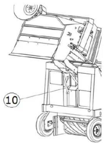
natural_image
Technical line drawing of a mechanical device with wheels and a labeled component (no readable text or symbols)Abbildung 2
text_image
Technical diagram of a mechanical vehicle with numbered parts labeled ①, ②, and ③.Abbildung 3
3.4. ZENTRALE BÜRSTE
text_image
Technical diagram of a mechanical device with labeled components, showing internal structure and numbered parts.Abbildung 4
3.8. ABFALLBEHÄLTER
text_image
Technical diagram of a mechanical device with numbered parts and directional arrows indicating motion or assembly.Abbildung 5
3.9. BEHÄLTERKLAPPE
natural_image
Technical line drawing of a mechanical device with wheels and a multi-barrel top component (no text or symbols)
natural_image
Pure technical line drawing of a mechanical component with no text or symbols
natural_image
Technical line drawing of a mechanical component with an arrow indicating direction (no text or symbols)Abbildung 6
natural_image
Technical line drawing of a ship's interior and steering wheel (no text or symbols)Abbildung 8

natural_image
Technical line drawing of a car interior showing structural components and directional arrows (no text or symbols)
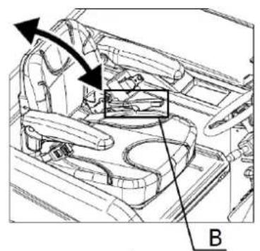
natural_image
Technical line drawing of a car interior showing structural components and a highlighted section (no text or symbols)
natural_image
Line drawing of a folded paper or scroll with an arrow pointing upward (no text or symbols)Abbildung 9

natural_image
Technical line drawing of a car interior showing structural components and airflow direction (no text or symbols)C

natural_image
Diagram of a streamlined object with internal structure and directional arrow (no text or symbols)text_image
Diagram of a vehicle's steering wheel and dashboard with directional arrows indicating rotation or movement, labeled with number 1.Abbildung 10
text_image
Technical diagram of a mechanical frame with labeled components 1 and 2Abbildung 11
text_image
Technical diagram of a mechanical device with numbered components for identificationAbbildung 12
text_image
ON OFF ST G LAbbildung 13
4.3.4. GASPEDAL
natural_image
Technical diagram of a vehicle's internal components with directional arrows indicating movement (no text or labels)Abbildung 14
text_image
Diagram showing three vertical components with red arrows indicating direction and surrounding icons, likely illustrating a mechanical or electrical component assembly.Abbildung 15
natural_image
3D mechanical assembly diagram showing directional arrows and component placement (no text or symbols)Abbildung 16
text_image
Three-panel diagram showing a control panel with directional arrows and icons, likely illustrating a system or operation sequence.Abbildung 17
natural_image
Technical line drawing of a mechanical frame assembly (no text or symbols)
text_image
A - B CAbbildung 20

text_image
B AAbbildung 21

text_image
BAbbildung 22
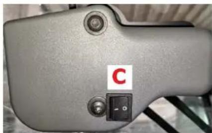
natural_image
Close-up of a gray mechanical device with a red label 'C' and a black control switch (no readable text or symbols beyond the label)Abbildung 23
text_image
Technical line drawings of three different agricultural machinery components with numbered labelsAbbildung 24
natural_image
Technical line drawing of a mechanical assembly with two views (top and side), no visible text or symbolsAbbildung 25
natural_image
Technical line drawing of an internal machine or enclosure with a magnified inset showing a close-up detail (no text or symbols present)Abbildung 26
natural_image
Technical line drawing of a mechanical device with two views (top and side), showing internal components and mounting base (no text or symbols)Abbildung 27
natural_image
Technical line drawing of a mechanical device with internal components and a close-up inset showing a component detail (no text or symbols present)Abbildung 28


natural_image
Technical line drawing of a mechanical component with an arrow indicating direction (no text or symbols present)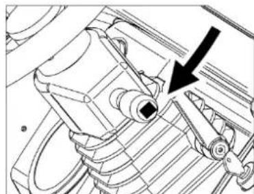
natural_image
Technical line drawing of a mechanical component with a black arrow pointing to a specific feature (no text or symbols present)Abbildung 30
natural_image
Technical line drawing of a mechanical component with a black arrow indicating direction (no text or symbols)
natural_image
Technical line drawing of a mechanical assembly with no visible text or symbolsAbbildung 31
natural_image
Technical diagram of a mechanical device with directional arrows indicating motion (no text or symbols present)Abbildung 32
natural_image
3D mechanical assembly diagram showing shafts and housing with red directional arrows (no text or symbols)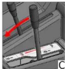
natural_image
3D mechanical assembly diagram showing a shaft and two vertical rods with a red arrow indicating motion (no text or symbols)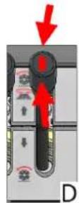
Abbildung 33
8.10. SEITENBÜRSTE
natural_image
Technical diagram showing three views (A, B, C) of a mechanical component with red arrows indicating direction, no text or symbols present.
natural_image
3D mechanical assembly diagram showing a component with red arrows indicating motion, no visible text or symbolsAbbildung 34
8.11. ABSAUGUNG
natural_image
Technical line drawing of a mechanical device with internal components and directional arrows indicating motion (no text or symbols)Abbildung 38

text_image
Technical diagram of a cleaning or dust removal device with labeled parts and exploded viewsAbbildung 39
text_image
Technical diagram of a sewing machine with numbered parts labeled 1, 2, and 3Abbildung 41
natural_image
Technical line drawing of a mechanical device with labeled components (no readable text or symbols)Abbildung 43
KAPITEL 12 - TRANSPORT, HANDLING UND AUSSERBETRIEBNAHME
text_image
Technical diagram of a mechanical assembly with numbered components labeled 1 to 4
text_image
Technical diagram of a machine with numbered components labeled 5, 6, and 7Abbildung 44
14.4. ZENTRALE BÜRSTE

VORGANG, DER BEI ABGESTELLTEM UND KALTEM MOTOR UND MIT HANDSCHUHEN, SCHUTZBRILLE UND ATEMSCHUTZGERÄT DURCHGEFÜHRT WERDEN MUSS. BEGINNEN SIE MIT DER INSPEKTION ERST DANN, NACHDEM SIE DIE SICHERHEITSLEISTE EINGESETZT HABEN (NR. 4.4.1).
text_image
Technical diagram of a mechanical device with numbered components for identificationAbbildung 45
natural_image
Technical line drawing of a mechanical device with rollers and gears (no text or symbols)
natural_image
Technical line drawing of a mechanical component with a circular base and threaded shaft (no text or symbols)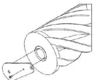
natural_image
Technical line drawing of a mechanical component with helical grooves and a cylindrical shaft (no text or symbols)
natural_image
Technical line drawing of a mechanical component with a cylindrical shaft and flanged base (no text or symbols)Abbildung 46

text_image
Technical diagram of a mechanical device with labeled parts, showing assembly and component details.Abbildung 47
text_image
Technical diagram of an industrial machine with seven labeled components, showing exploded and assembled views.Abbildung 48
text_image
EACCE Made in Italy Type Code Weight Kg Volts S/N Year / Week KW LwA PO n. dB 2 %text_image
Technical diagram of a vehicle's internal components with numbered parts for identification.Figura 1
text_image
Technical diagram of a cleaning or dust removal machine with numbered components for identification.
text_image
⑩Figura 2
text_image
Technical diagram of a mechanical vehicle with numbered parts labeled ①, ②, and ③.Figura 3
3.4. CEPILLO CENTRAL
natural_image
Technical line drawing of a mechanical device with internal components and labeled parts (no text or symbols present)Figura 4
3.8. CONTENEDOR DE RESIDUOS
text_image
Technical diagram of a mechanical device with numbered components and directional arrows indicating motion or assembly.Figura 5
3.9. FLAP CONTENEDOR
natural_image
Technical line drawing of a mechanical device with wheels and a speaker (no text or symbols)
natural_image
Pure technical line drawing of a mechanical component with no text or symbols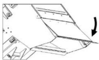
natural_image
Technical line drawing of a mechanical component with an arrow indicating direction (no text or symbols)Figura 6
3.10. DATOS TÉCNICOS
CARACTERÍSTICAS TÉCNICAS U.M. SWL R 1300
natural_image
Technical line drawing of a ship's interior components including steering wheel, dashboard, and control panel (no text or labels)Figura 8

natural_image
Technical diagram of a car interior showing structural components and directional arrows (no text or symbols)

natural_image
Technical line drawing of a vehicle interior showing structural components and a highlighted section (no text or symbols)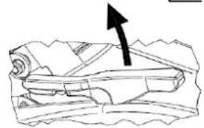
natural_image
Diagram of a mechanical component with an arrow indicating direction (no text or symbols present)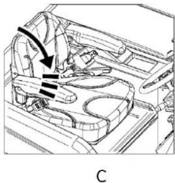
natural_image
Technical line drawing of a car interior showing steering wheel and dashboard (no text or symbols)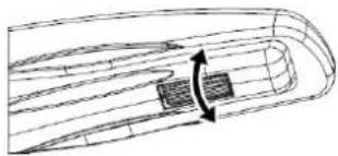
natural_image
Technical line drawing of a mechanical component with internal channels and directional arrows (no text or symbols)Figura 9
text_image
Diagram of a vehicle's steering wheel and dashboard with directional arrows indicating rotation or movement, labeled with number 1.Figura 10
text_image
Technical diagram of a mechanical device with labeled components 1 and 2, showing internal structure and assembly details.Figura 11
text_image
Technical diagram of a mechanical device with numbered components for identificationFigura 12
natural_image
Technical diagram of a vehicle's internal components with directional arrows indicating movement (no text or labels)Figura 14
natural_image
Diagram of three vertical cylindrical components with red arrows indicating direction, mounted on a base panel (no text or symbols present)Figura 15
4.3.9. MANDO CEPILLO CENTRAL
natural_image
3D mechanical assembly diagram showing lever mechanism with red arrows indicating motion (no text or symbols)Figura 16
4.3.11. INTERRUPTOR DE CEPILLO LATERAL
text_image
Three-panel diagram showing a control panel with directional arrows and icons, likely illustrating a system or operation sequence.Figura 17
4.3.12. REGULADOR VELOCIDAD CEPILLO LATERAL
natural_image
Technical line drawing of a mechanical frame assembly (no text or symbols)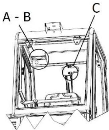
text_image
A - B CFigura 20

text_image
B AFigura 21

text_image
BFigura 22
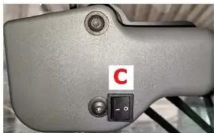
natural_image
Close-up of a gray electronic device with a black button labeled 'C' and a small square symbol, no readable text or symbols beyond the label.Figura 23
natural_image
Technical line drawing of a mechanical assembly with two views (top and side), showing internal components and structural details (no text or symbols)Figura 25
natural_image
Technical line drawing of an industrial machine interior with a magnified inset showing internal components (no text or symbols)Figura 26
CAPÍTULO 5 - CONDICIONES DE USO PERMITIDAS Y NO PERMITIDAS
5.1. CONDICIONES DE USO PERMITIDAS
natural_image
Technical line drawing of a mechanical device with two views (top and side), showing internal components and mounting base (no text or symbols)Figura 27
natural_image
Technical line drawing of a mechanical device with internal components and a close-up inset showing a component detail (no text or symbols present)Figura 28


natural_image
Technical line drawing of a mechanical component with an arrow indicating direction (no text or symbols)
natural_image
Technical line drawing of a mechanical component with a black arrow pointing to a specific part (no text or symbols present)Figura 30
natural_image
Technical line drawing of a mechanical assembly with no visible text or symbols
natural_image
Technical line drawing of a mechanical component with an arrow indicating direction (no text or symbols present)Figura 31
natural_image
Technical diagram of a mechanical device with arrows indicating motion or force direction (no text or symbols present)Figura 32
natural_image
Four-panel diagram showing mechanical assembly steps with red arrows indicating motion direction (no text or symbols)Figura 33
8.10. CEPILLO LATERAL
natural_image
Technical line drawing of a mechanical device with no visible text or symbolsFigura 37
natural_image
Technical line drawing of a truck's internal components with an inset showing mechanical parts (no text or symbols)Figura 38

natural_image
Technical line drawing of a cleaning or dust removal machine with labeled components (no text or symbols present)Figura 39
text_image
Technical diagram of a device with numbered components, likely illustrating a mechanical or electrical assembly.Figura 41
natural_image
Technical line drawing of a mechanical device with labeled parts (no readable text or symbols)Figura 43
text_image
Technical diagram of a mechanical assembly with numbered components labeled 1 to 4
text_image
Technical diagram of a machine with numbered components labeled 5, 6, and 7Figura 44
14.4. CEPILLO CENTRAL

text_image
Technical diagram of a mechanical device with numbered components for identificationFigura 45
natural_image
Technical line drawing of a mechanical device with rollers and gears (no text or symbols)
natural_image
Technical line drawing of a mechanical component with curved and straight lines (no text or symbols)
natural_image
Technical line drawing of a mechanical component with helical grooves and a cylindrical shaft (no text or symbols)
natural_image
Technical line drawing of a mechanical component with a cylindrical shaft and flanged base (no text or symbols)Figura 46

text_image
Technical diagram of a mechanical device with labeled parts, showing assembly and component details.Figura 47
text_image
Technical diagram of an industrial machine with seven labeled components, showing exploded and assembled views.Figura 48
14.10. LIMPIEZA DEL CONTENEDOR DE RESIDUOS

text_image
EACCE Made in Italy Type S/N Code Year / Week Weight Kg KW PO n. Volts LwA dB 2 %ROZDZIAŁ 2 - CELE / POSTANOWIENIA
text_image
Technical diagram of a mechanical device with numbered parts for identification and assembly reference.Rysunek 1
text_image
Technical diagram of a cleaning or dust removal machine with numbered components for identification.
text_image
10Rysunek 2
text_image
Technical diagram of a mechanical vehicle with numbered parts labeled ①, ②, and ③.Rysunek 3
3.4. SZCZOTKA CENTRALNA
text_image
Technical diagram of a mechanical device with labeled components and structural detailsRysunek 4
3.8. POJEMNIK NA ODPADY
text_image
Technical diagram of a mechanical device with numbered components and directional arrows indicating motion or assembly.Rysunek 5
3.9. KLAPA POJEMNIKA
natural_image
Technical line drawing of a mechanical device with multiple views and components, showing exploded and assembled views (no text or symbols)Rysunek 6
CHARAKTERYSTYKA TECHNICZNA J.M. SWL R 1300
natural_image
Technical line drawing of a ship's interior and steering wheel (no text or symbols)Rysunek 8

natural_image
Technical line drawing of a car interior showing structural components and directional arrows (no text or symbols)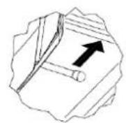
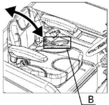
natural_image
Technical line drawing of a car interior showing structural components and airflow direction (no text or symbols)
natural_image
Diagram of a rolled-up document with an arrow pointing to it, no text or symbols present
natural_image
Interior view of a car showing dashboard and steering wheel (no text or symbols)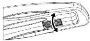
natural_image
Diagram of a boat hull with visible hull lines and a central rectangular object, no text or symbols presentRysunek 9
text_image
Diagram of a vehicle's steering wheel and dashboard with labeled components and directional arrows indicating rotation or movement.Rysunek 10
text_image
Technical diagram of a mechanical device with labeled components 1 and 2Rysunek 11
4.3. URZĄDZENIA STERUJĄCE
4.3.1. UMIEJSCOWIENIE ELEMENTÓW STERUJĄCYCH I OPIS
text_image
Technical diagram of a mechanical device with numbered components for identificationRysunek 12
natural_image
Technical diagram of a mechanical component with directional arrows indicating motion or force (no text or symbols present)Rysunek 14
text_image
Diagram showing three vertical components with red arrows indicating direction and directional changes, possibly illustrating a mechanical or electrical system.Rysunek 15
4.3.9. STEROWNIK DO SZCZOTKI CENTRALNEJ
natural_image
3D mechanical assembly diagram showing directional arrows and component labels (no readable text or symbols)Rysunek 16
4.3.11. WYŁACZNIK SZCZOTKI BOCZNEJ
text_image
Three-panel diagram showing a device with directional arrows and icons, likely illustrating a control or operation sequence.Rysunek 17
4.3.12. REGULATOR PRĘDKOŚCI SZCZOTKI BOCZNEJ
natural_image
Technical line drawing of a mechanical device with labeled component A (no text or symbols beyond label)
text_image
A - B CRysunek 20
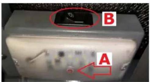
text_image
B ARysunek 21

text_image
BRysunek 22

natural_image
Close-up of a gray electronic device with a black control switch labeled 'C' and a red letter, no readable text or symbols beyond the label.Rysunek 23
natural_image
Technical line drawing of a mechanical assembly with two views (top and side), showing internal components and structural details (no text or symbols)Rysunek 25
natural_image
Technical line drawing of an industrial machine interior with a magnified inset showing internal components (no text or symbols)Rysunek 26
ROZDZIAŁ 5 - DOZWOLONE I NIEDOZWOLONE WARUNKI UŻYWANIA
5.1. DOZWOLONE WARUNKI UŻYWANIA
natural_image
Technical line drawing of a mechanical device with wheels and control panel (no text or symbols)
natural_image
Technical line drawing of a mechanical device with mounting base and internal components (no text or symbols)Rysunek 27
natural_image
Technical line drawing of a mechanical device with internal components and a magnified inset showing a component detail (no text or symbols present)Rysunek 28


natural_image
Technical line drawing of a mechanical component with an arrow indicating upward motion (no text or symbols)
natural_image
Technical line drawing of a mechanical component with a black arrow pointing to a specific feature (no text or symbols present)Rysunek 30
natural_image
Technical line drawing of a mechanical component with a black arrow indicating direction (no text or symbols)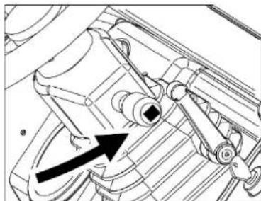
natural_image
Technical diagram of a mechanical component with an arrow indicating direction (no text or symbols present)Rysunek 31
natural_image
Mechanical device with two black arrows indicating motion or force direction (no text or symbols)Rysunek 32
natural_image
Technical line drawing of a mechanical device with an inset showing a tool interacting with a component (no text or symbols present)Rysunek 38
text_image
Technical diagram of a cleaning or dust removal device with labeled parts and exploded viewsRysunek 39
text_image
Technical diagram of a device with numbered components and directional arrows indicating flow or movementRysunek 41
natural_image
Technical line drawing of a mechanical device with labeled parts and mounting holes (no text or symbols present)Rysunek 43
ROZDZIAŁ 12 - TRANSPORT, PRZEMIESZCZANIE I WYŁĄCZENIE Z EKSPLOATACJI
12.1. WYŁĄCZENIE Z EKSPLOATACJI

CZYNNOŚCI WYKONAĆ NA WYŁĄCZONYM I ZIMNYM SILNIKU.
text_image
Technical diagram of a mechanical assembly with numbered components labeled 1 to 4
text_image
Technical diagram of a machine with numbered components labeled 5, 6, and 7Rysunek 44
14.4. SZCZOTKA CENTRALNA

CZYNNOŚĆ MOŻE BYĆ WYKONANA PO WCZEŚNIEJSZYM WYŁĄCZENIU I OCHŁODZENIU SILNIKA I ZASTOSOWANIU RĘKAWIC I OKULARÓW OCHRONNYCH ORAZ ŚRODKÓW DO OCHRONY DRÓG ODDECHOWYCH. KONTROLE WYKONAĆ DOPIERO PO WCZEŚNIEJSZYM WPROWADZENIU DRAŻKA BEZPIECZEŃSTWA (PKT. 4.4.1).
text_image
Technical diagram of a mechanical device with numbered components for identificationRysunek 45
text_image
Technical diagram of a mechanical device with labeled parts 1 and 2, showing internal components and assembly.Rysunek 47
text_image
Technical diagram of an industrial machine with seven labeled components, showing exploded and assembled views.Rysunek 48
14.10. CZYSZCZENIE POJEMNIKA NA ODPADY

CZYNNOŚĆ MOŻE BYĆ WYKONANA PO WCZEŚNIEJSZYM WYŁĄCZENIU I OCHŁODZENIU SILNIKA I ZASTOSOWANIU RĘKAWIC I OKULARÓW OCHRONNYCH ORAZ ŚRODKÓW DO OCHRONY DRÓG ODDECHOWYCH. UPEWNIĆ SIĘ, ŻE OSOBY NIEUPOWAŻNIONE DO WYKONANIA DZIAŁAŃ NIE MOGA UZYSKAĆ DOSTĘPU.
text_image
EACCE Made in Italy Type S/N Code Year / Week Weight Kg KW PO n. Volts LwA dB 2 %ГЛАВА 2 - ЦЕЛИ / НАМЕРЕНИЯ
text_image
Technical diagram of a vehicle's internal components with numbered parts for identification.Рис. 1
text_image
Technical diagram of a mechanical device with numbered components and exploded view, likely forklift or maintenance.Рис. 2
text_image
Technical diagram of a mechanical vehicle with numbered parts labeled ①, ②, and ③.Рис. 3
text_image
Technical diagram of a mechanical device with labeled components, showing internal structure and mounting points.Рис. 4
text_image
Technical diagram of a mechanical device with numbered components and directional arrows indicating motion or assembly.Рис. 5
natural_image
Technical line drawing of a mechanical device with wheels and a multi-tiered tower (no text or symbols)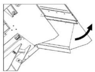
natural_image
Technical line drawing of a mechanical component with an arrow indicating rotation (no text or symbols)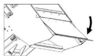
natural_image
Pure technical line drawing of a mechanical component with no text or symbolsРис. 6
natural_image
Technical line drawing of a ship's interior components including steering wheel, dashboard, and control panel (no text or labels)Рис. 8

natural_image
Technical line drawing of a car interior showing engine and dashboard components with directional arrows (no text or symbols)
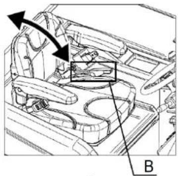
natural_image
Technical line drawing of a vehicle interior showing engine compartment and dashboard (no text or symbols)
natural_image
Illustration of a rolled document with an arrow pointing upward (no text or symbols)
natural_image
Technical line drawing of a car interior showing seat, dashboard, and steering wheel (no text or symbols)
natural_image
Technical line drawing of a mechanical component with internal channels and directional arrows (no text or symbols)Рис. 9
text_image
Diagram of a vehicle's steering wheel and dashboard with directional arrows indicating rotation or movement, labeled with number 1.Рис. 10
text_image
Technical diagram of a mechanical device with labeled components 1 and 2Рис. 11
text_image
Technical diagram of a mechanical device with numbered components for identificationРис. 12
natural_image
Technical diagram of a mechanical assembly with directional arrows indicating motion or force (no text or symbols present)Рис. 14
text_image
Diagram showing three vertical connectors with red arrows indicating direction and surrounding components, likely illustrating a mechanical or electrical system.Рис. 15
natural_image
3D mechanical assembly diagram showing directional arrows and component labels (no readable text or symbols)Рис. 16
text_image
Three-panel diagram showing a door switch mechanism with red arrows indicating clockwise motion and icons for cleaning, cleaning, and cleaning.Рис. 17
natural_image
Technical line drawing of a mechanical frame assembly (no text or symbols)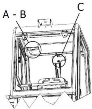
text_image
A - B CРис. 20
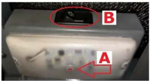
text_image
B AРис. 21
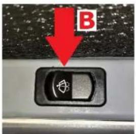
text_image
BРис. 22

natural_image
Close-up of a gray mechanical component with a red letter 'C' and a black control switch (no readable text or symbols beyond the label)Рис. 23
natural_image
Technical line drawing of a mechanical assembly with two views (top and side), no visible text or symbolsРис. 25
natural_image
Technical line drawing of an industrial machine interior with a magnified inset showing internal components (no text or symbols)Рис. 26
natural_image
Technical line drawing of a mechanical device on a pallet, showing internal components and a close-up inset (no text or symbols)
natural_image
Technical line drawing of a mechanical device with mounting base and internal components (no text or symbols)Рис. 27
natural_image
Technical line drawing of a mechanical device with internal components and a magnified inset showing a detail (no text or symbols)Рис. 28


natural_image
Technical line drawing of a mechanical component with an arrow indicating direction (no text or symbols present)
natural_image
Technical line drawing of a mechanical component with a black arrow pointing to a specific feature (no text or symbols present)Рис. 30
natural_image
Technical line drawing of a mechanical component with a black arrow indicating direction (no text or symbols)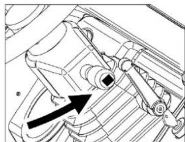
natural_image
Technical line drawing of a mechanical assembly with no visible text or symbolsРис. 31
natural_image
Mechanical assembly diagram showing two downward arrows pointing to a component (no text or symbols present)Рис. 32
natural_image
Technical line drawing of a mechanical device with no visible text or symbols

natural_image
Technical line drawing of a mechanical device with a directional arrow indicating motion (no text or symbols present)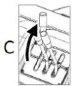
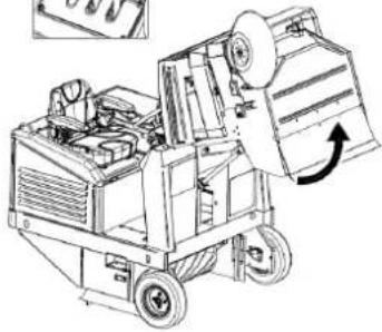
natural_image
Technical line drawing of a mechanical device with wheels and a paper roll, showing internal components and motion direction (no text or symbols)Рис. 37
natural_image
Technical line drawing of a mechanical device with an arrow indicating rotation (no text or symbols present)Рис. 38

text_image
Technical diagram of a mechanical device with labeled parts and exploded viewsРис. 39
text_image
Technical diagram of a device with numbered components and directional arrows indicating movement or flow.Рис. 41
natural_image
Technical line drawing of a mechanical device with labeled components (no readable text or symbols)Рис. 43
text_image
Technical diagram of a mechanical assembly with numbered components labeled 1 to 4
text_image
Technical diagram of a machine with numbered components labeled 5, 6, and 7Рис. 44
text_image
Technical diagram of a mechanical device with numbered components for identificationРис. 45
natural_image
Technical line drawing of a mechanical device with rollers and gears (no text or symbols)
natural_image
Technical line drawing of a mechanical component with curved and straight lines (no text or symbols)
natural_image
Technical line drawing of a mechanical component with helical grooves and a cylindrical shaft (no text or symbols)
natural_image
Technical line drawing of a mechanical component with no visible text or symbolsРис. 46

text_image
Technical diagram of a mechanical device with labeled parts, showing assembly and component details.Рис. 47
text_image
Technical diagram of an industrial machine with seven labeled components, showing exploded and assembled views.Рис. 48
text_image
EACCE Made in Italy Type S/N Code Year / Week Weight Kg KW PO n. Volts LwA dB 2 %KAPITTEL 2 - DOELEINDEN / BEDOELINGEN
text_image
Technical diagram of a vehicle's internal components with numbered parts for identification.Afbeelding 1
text_image
Technical diagram of a cleaning or dust removal machine with numbered components for identification.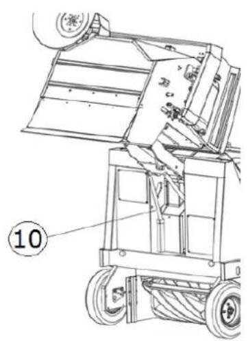
text_image
⑩Afbeelding 2
text_image
Technical diagram of a truck with numbered parts labeled ①, ②, and ③ for identification.Afbeelding 3
text_image
Technical diagram of a mechanical device with labeled components, showing internal structure and assembly lines.Afbeelding 4
3.8. AFVALBAK
text_image
Technical diagram of a mechanical device with numbered components and directional arrows indicating motion or assembly.Afbeelding 5
3.9. FLAP BAK
natural_image
Technical line drawing of a mechanical device with multiple views and components, no visible text or symbolsAfbeelding 6
natural_image
Technical line drawing of a ship's interior components including steering wheel, dashboard, and control panel (no text or labels)Afbeelding 8

natural_image
Technical line drawing of a car interior showing dashboard and steering wheel (no text or symbols)

natural_image
Interior view of a car dashboard and steering wheel (no text or symbols visible)
natural_image
Diagram of a rolled-up document with an arrow pointing to it, no text or symbols presentAfbeelding 9
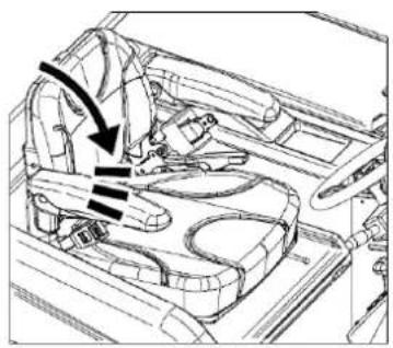
natural_image
Technical line drawing of a car interior showing structural components and directional arrows (no text or symbols)C
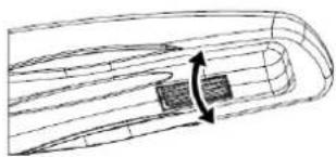
natural_image
Diagram of a streamlined object with internal flow lines and a highlighted section (no text or symbols)text_image
Diagram of a vehicle's steering wheel and dashboard with directional arrows indicating rotation or movement, labeled with number 1.Afbeelding 10
text_image
Technical diagram of a mechanical frame with labeled components 1 and 2Afbeelding 11
4.3. BEDIENINGSELEMENTEN
4.3.1. PLAATS EN BESCHRIJVING VAN DE BEDIENINGSELEMENTEN
text_image
Technical diagram of a mechanical device with numbered components for identificationAfbeelding 12
natural_image
Technical diagram of a mechanical component with directional arrows indicating motion or force (no text or symbols present)Afbeelding 14
text_image
Diagram showing three mechanical components with red arrows indicating directional movement, possibly illustrating a motion or force system.Afbeelding 15
4.5.6. BEDIENING CENTRALE BORSTEL
natural_image
Mechanical assembly diagram showing directional arrows and component placement (no text or symbols)Afbeelding 16
4.5.8. SCHAKELAAR ZIJDELINGSE BORSTEL
text_image
Three-panel diagram showing a control panel with directional arrows and icons, likely illustrating a system or operation sequence.Afbeelding 17
4.5.9. HENDEL ROTATIESNELHEID ZIJDELINGSE BORSTEL
natural_image
Technical line drawing of a mechanical frame assembly (no text or symbols)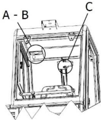
text_image
A - B CAfbeelding 20

text_image
B AAfbeelding 21

text_image
BAfbeelding 22

natural_image
Close-up of a gray electronic device with a red 'C' label and a black control switch (no readable text or symbols beyond the label)Afbeelding 23
text_image
Technical line drawings of three different agricultural machinery models with numbered labelsAfbeelding 24
4.6.2. BEVEILIGINGEN VAN DE MOTORKAP, AFSCHERMING STOEL EN AFSCHERMING FILTERS
natural_image
Technical line drawing of a mechanical assembly with two views (top and side), showing internal components and structural details (no text or symbols)Afbeelding 25
natural_image
Technical line drawing of an industrial machine interior with a magnified inset showing internal components (no text or symbols)Afbeelding 26
KAPITTEL 5 - TOELAATBARE EN NIET-TOELAATBARE GEBRUIKSOMSTANDIGHEDEN
5.1. TOELAATBARE GEBRUIKSOMSTANDIGHEDEN
natural_image
Technical line drawing of a mechanical device with wheels and control panel (no text or symbols)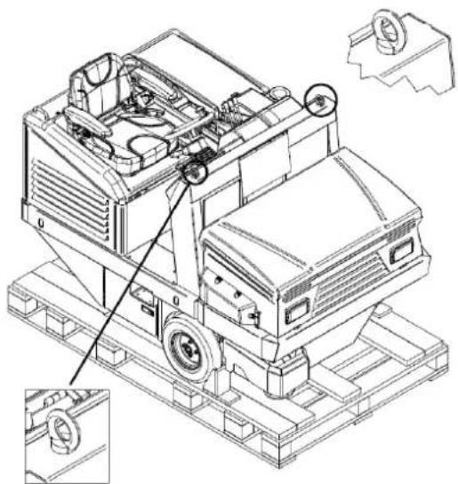
natural_image
Technical line drawing of a mechanical device with mounting base and internal components (no text or symbols)Afbeelding 27
natural_image
Technical line drawing of a mechanical device with internal components and a magnified inset showing a detail (no text or symbols)Afbeelding 28


natural_image
Technical line drawing of a mechanical component with an arrow indicating direction (no text or symbols)
natural_image
Technical line drawing of a mechanical component with a black arrow pointing to a specific part (no text or symbols present)Afbeelding 30
natural_image
Technical line drawing of a mechanical assembly with no visible text or symbols
natural_image
Technical line drawing of a mechanical component with no visible text or symbolsAfbeelding 31
natural_image
Technical line drawing of a mechanical device with two arrows indicating motion or force direction (no text or symbols present)Afbeelding 32
natural_image
3D mechanical assembly diagram showing cylindrical components and a base plate with red directional arrows (no text or symbols)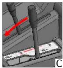
natural_image
3D mechanical assembly diagram showing a shaft and two vertical rods with a red arrow indicating motion (no text or symbols)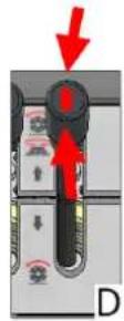
Afbeelding 33
8.10. ZIJDELINGSE BORSTEL
natural_image
3D rendered mechanical components with a red arrow indicating direction (no text or symbols)

natural_image
3D rendered mechanical components with a red arrow indicating direction (no text or symbols)
Afbeelding 34
8.11. OPZUIGEN
8.13. LEDIGING AFVALBAK
natural_image
Technical line drawing of a mechanical device with an inset showing a close-up of internal components (no text or symbols)Afbeelding 38

text_image
Technical line drawing of a cleaning or dust cleaning machine with labeled components and exploded viewsAfbeelding 39
text_image
Technical diagram of a device with numbered components and directional arrows indicating movement or flowAfbeelding 41
natural_image
Technical line drawing of a mechanical device with labeled components and parts (no readable text or symbols)Afbeelding 43
KAPITTEL 12 - TRANSPORT, VERPLAATSING EN BUITENDIENSTSTELLING
12.1. BUITENDIENSTSTELLING

HANDELIND DIE MOETEN WORDEN VERRICHT BIJ AFGEZETTE EN AFGEKOELDE MOTOR.
text_image
Technical diagram of a mechanical assembly with numbered components labeled 1 to 4
text_image
Technical diagram of a machine with numbered components labeled 5, 6, and 7Afbeelding 44

HANDELING DIE MOET WORDEN VERRICHT BIJ AFGEZETTE EN AFGEKOELDE MOTOR EN MET GEBRUIK VAN HANDSCHOENEN, VEILIGHEIDSBRIL EN BESCHERMING VAN DE LUCHTWEGEN. VERRICHT DE INSPECTIE PAS NA DE VEILIGHEIDSBALK TE HEBBEN AANGEBRACHT (PAR. 4.4.1).
text_image
Technical diagram of a mechanical device with numbered components for identificationAfbeelding 45
natural_image
Technical line drawing of a mechanical assembly with coiled components and no visible text or symbols
natural_image
Technical line drawing of a mechanical component with no visible text or symbols
natural_image
Technical line drawing of a mechanical component with helical grooves and a cylindrical shaft (no text or symbols)
natural_image
Technical line drawing of a mechanical component with a conical base and cylindrical shaft (no text or symbols)Afbeelding 46

CONTROLEER OF DE VEILIGHEIDSBALK IS VERWIJDERD ALVORENS DE AFVALBAK OMLAAG TE VERPLAATSEN.
14.5. ZIJDELINGSE BORSTEL

HANDELING DIE MOET WORDEN VERRICHT BIJ AFGEZETTE EN AFGEKOELDE MOTOR EN MET GEBRUIK VAN HANDSCHOENEN, VEILIGHEIDSBRIL EN BESCHERMING VAN DE LUCHTWEGEN.
text_image
Technical diagram of a sewing machine with labeled parts 1 and 2, showing mechanical components and base structure.Afbeelding 47
14.6. SPECIFIEK ONDERHOUD VOOR VERBRANDINGSMOTOREN


text_image
Technical diagram of an industrial machine with seven labeled components, showing exploded and assembled views.Afbeelding 48
14.10. REINIGING VAN DE AFVALBAK

HANDELING DIE MOET WORDEN VERRICHT BIJ AFGEZETTE EN AFGEKOELDE MOTOR EN MET GEBRUIK VAN HANDSCHOENEN, VEILIGHEIDSBRIL EN BESCHERMING VAN DE LUCHTWEGEN. ZORG ERVOOR DAT NIET BIJ DE HANDELINGEN BETROKKEN PERSONEN GEEN TOEGANG HEBBEN.