Eco Gamma 103 - Fan CasaFan - Free user manual and instructions
Find the device manual for free Eco Gamma 103 CasaFan in PDF.

User questions about Eco Gamma 103 CasaFan
0 question about this device. Answer the ones you know or ask your own.
Ask a new question about this device
Download the instructions for your Fan in PDF format for free! Find your manual Eco Gamma 103 - CasaFan and take your electronic device back in hand. On this page are published all the documents necessary for the use of your device. Eco Gamma 103 by CasaFan.
USER MANUAL Eco Gamma 103 CasaFan
natural_image
Line drawing of a five-blade propeller with central hub and four blades (no text or symbols)ECO GAMMA 103
ECO GAMMA 137

text_image
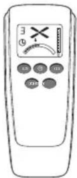
3 E X FB OFF XXBDECKENVENTILATOR
CEILING FAN
VENTILATEUR DE PLAFOND
VENTILATORE DA SOFFITTO
VENTILADOR DE TECHO
STROPNÍ VENTILÁTOR
PLAFONDVENTILATOR
WENTYLATOR SUFITOWY
CE
Radio frequency: 433,92 MHz
Maximum transmitting power:<10dBm
natural_image
Simple line drawing of a person sitting on a bench using a book (no text or symbols)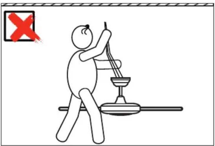
text_image
Illustration showing a person using a tool to clean or inspect a device, with a red 'X' symbol indicating no defect.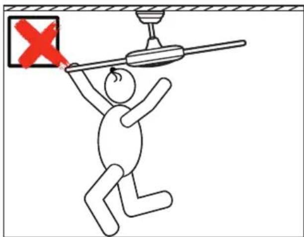
text_image
Safety warning illustration showing a person using a pole with a red X mark indicating failure or hazard, above a ceiling fixture.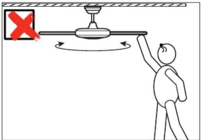
text_image
Diagram showing a person using a pulley system to lift a ceiling, with a red X mark indicating the left side of the device.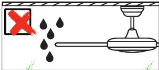
text_image
Safety warning diagram showing a water drop labeled 'X' and a pipe with a stopper, indicating incorrect safety.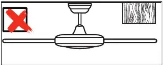
natural_image
Simple line drawing of a ceiling fan with a handle and wooden panel, no text or symbols present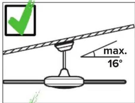
text_image
max. 16°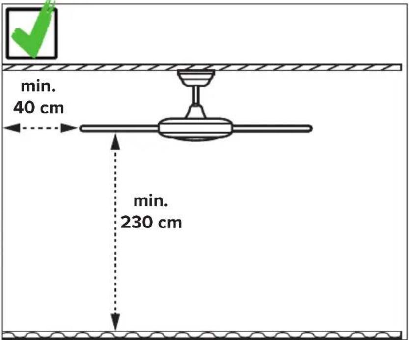
Installation ceiling bracket 32-34
Electrical connections 43
Assembling....35–45
Initial operation/Recoding 46–48
Operation....49–51
Troubleshooting....53
Cleaning/Maintenance 53
Hints and Tips....60
Disposal....64
IT
INDICE
About this operating manual
Before using the CasaFan fan, read the mounting and operating manual carefully. For the safety of persons it is important to follow these instructions!
| Explanation of symbols: | |
| WARNING: Electric voltage! | ATTENTION: |
| Warns you of immediate danger to life. Indicates risks to health and possible damage to property. | |
| With electrical devices, there is a danger to life from electric shock if used improperly, installed incorrectly or if the safety instructions are not observed! | |
SAFETY ADVICES
- Keep the operating manual within reach. Never pass the fan onto another person without the operating manual.
- This ceiling fan is for circulating dry room air. Their use in machines, outside, in garages, in moist or wet rooms or rooms in danger of fire or explosion, is not permitted.
- This appliance can be used by children aged from 8 years and above and persons with reduced physical, sensory or mental capabilities or lack of experience and knowledge if they have been given supervision or instruction concerning use of the appliance in a safe way and understands the hazards involved.
- Cleaning and user maintenance shall not be made by children without supervision.
- If unusual oscillating movement is observed, immediately stop using the ceiling fan and contact the manufacturer, its service agent or suitably qualified persons.
- Replacement of parts of the safety suspension system device shall be performed by the manufacturer, its service agent or suitably qualified persons.
- Mounting of the suspension system shall be performed by the manufacturer, its service agent or suitably qualified persons.
GB
- Before accessing the connection and installation, the current must be disconnected on all poles (fuse in fuse box).
- Children shall not play with the appliance.
- Ensure that the fan is switched off from the supply mains before service and maintenance.
- The electrical connection and electrical maintenance of this fan may only be carried out by a trained electrician, a skilled electrician or an appropriately qualified person.
- The voltage details on the rating label are to conform with the available mains voltage.
- Do not run the cables over sharp edges and under no circumstances squeeze the cables during installation.
- Only operate the ceiling fan when completely assembled!
- WARNING! The mains connection requires a two-pole isolating switch with a contact opening width of at least 3 mm. The disconnecting device must be integrated into the fixed wiring according to the valid technical regulations.
- The electrical safety of the fan is only guaranteed if the earthing system of the building installation is installed in accordance with the regulations and the fan is connected to it.
- The mains connection to which the fan is connected must comply with the applicable local standards.
- Choose a safe place for installation and make sure that there are no objects within the area of rotation.
- The construction and fixture of the holder and ceiling is to be able to bear 4 times the weight of the fan when being moved.
- None of the fan blades are to be less than 2.3 m from the ground.
- Keep the fan away from heat sources. The minimum distance to radiant heaters and stoves is 1.5 m.
- Before first using after the setup, all electrical and mechanical connections are to be checked in order to prevent any fall, fire or electric shock.
Observe notes on disposal!
Our ceiling fans are quality products and designed for a long service life.
- Do not dispose of a appliance at the end of its service life and any batteries required to operate the appliance in household waste!
- Find out about local return and recycling possibilities and use the existing collection points in your area for disposal.
- Dispose of packaging material that is no longer required in an environmentally friendly manner and inaccessible to children.
- There is a risk of suffocation for children by inhaling or swallowing parts of the packaging.
PARTS (Figure U, page 28)
Unpack the fan and compare the package contents for completeness. All the parts shown in the figure are to be present and undamaged.
| Technical data: | ||
| Type Eco Elements | 103 | Eco Elements 132 |
| Mains voltage 100 - 240 V | ~ | |
| Frequency 50/60 Hz | ||
| Power motor 1,0 - 14,6 W 1,1 - 26,4 W | ||
| Protection class I/IP20 | ||
| No. of speeds 6 (with remote control) | ||
| Dimensions ∅ × H (mm) 1100 × 350/270 1370 × 350/270 | ||
| Distance ceiling – blades | approx. 295/215 mm approx. 295/215 mm | |
| Weight approx. 8.1 kg 8.4 kg | ||
| Optional light kit | Leuchte Gamma #9511001 | |
| Service interval | once a year | |
| Subject to technical modifications. | ||
text_image
Exploded view diagram of a car brake system with numbered components and labeled partsDE EINZELTEILE
① Hanger Bracket ⑨ Downrod Support ⑯ b. Blade Screws (15×)
2 Canopy Screw (4×) 10 Downrod Support Screw (2×) 17 Bottom Cover
3 Terminal Block Clevis Pin 11 Remote Control 18
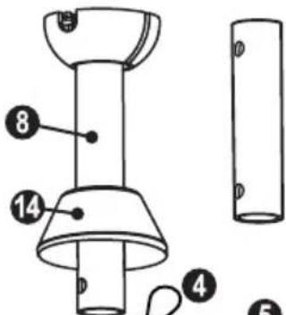
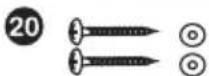
4 Safety Rope 12 Hairpin Clip 19 Screw for Blade Support (10×)
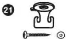
5 Fan Wire 13 Motor Assembly 20 Bracket Screw for Wood (2×)
6 Canopy 14 Upper Cover 21 Support Safety Rope
7 Canopy Screw Cover 15 Blade (5×) 22 Transport lock (3×)
8 Downrod and Hanger Ball 16 a. Blade Support (5×) 23 Mounting ring for low profile installation
FR PIÈCE DÉTACHÉE
text_image
Technical diagram of a mechanical device with numbered components and labeled parts18
text_image
3 0 IP 10 IP X490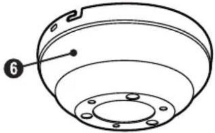
natural_image
Technical line drawing of a mechanical component with labeled part 6 (no text or symbols beyond label)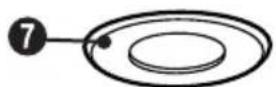
text_image
Technical diagram of a lamp with numbered components and labeled parts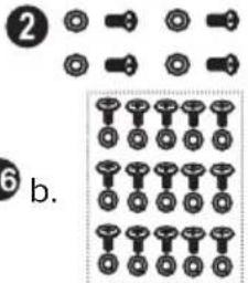
text_image
② ⑥ b.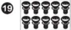

text_image
15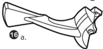
natural_image
Line drawing of a mechanical component with curved surfaces and a labeled section (16 a.)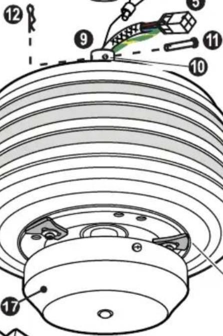
text_image
Technical diagram of a mechanical component with numbered parts and labeled parts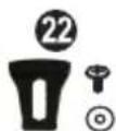

COMPONENTES
GB WARNING: Danger of electric shock! Before commencing installation, turn off electricity supply at the main power box or disconnect power by removing fuse.
⚠️ ATTENTION: Follow all installation directions. Improper installation can lead to injuries and material damage.
- The place of installation (ceiling) must have a load capacity of at least 34 kg.
- Use only for your type of ceiling suitable screws and plugs (not supplied).
1 Attach the hanger bracket ① with 2 screws. Tighten the screws.
2 Fasten the hook ② for the safety rope on the ceiling as shown.
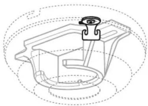
3 Remove the 3 transport locks 22 on the motor before starting assembly.
natural_image
Technical line drawing of a mechanical component with dashed circular outlines (no text or symbols)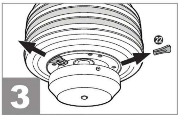
text_image
3 22GB Uninstall the clevis pin from the downrod, retain the clevis pin and hairpin clip for later. Install the canopy, cover ring and upper cover through downrod.
text_image
A ① ② ② ②GB Hang the pre-mounted ceiling fan into the ceiling bracket. Hang the safety cable in the hook provided for this purpose and pull it tightly downwards to secure it against leaking. Make the electrical connection as shown on page 43.
text_image
Technical diagram showing four steps of a device control or assembly process, labeled 1 to 4 with directional arrows and a 'KLICK!' button.DE Schieben Sie den Baldachin nach oben und verdrehen Sie ihn in den Bajonettverschluss mit den Baldachinschrauben. Ziehen Sie die 4 Baldachin-Schrauben fest. Drücken Sie den Abdeckring nach oben, bis er einrastet.
GB Slide the canopy up and twist it into the bayonet lock with the canopy screws. Fasten the 4 canopy screws. Press the cover ring upwards until it clicks into place.
FR Pousser le cache supérieur vers le haut et le tourner dans la fixation à baïonnette formée par les vis. Serrer les 4 vis et mettre en place le cache des vis par clipage.
IT Far scorrere il baldacchino e trasformarlo in baionetta raccordo con le viti baldacchino. Serrare le 4 viti a baldacchino.
Press servire sotto la copertura della chioma verso l'alto fino allo scatto.
ES Deslice la capota hacia arriba y gírela en el cierre de bayoneta con los tornillos de la capota. Apriete los 4 tornillos de la capota.
Empuje la cubierta inferior del toldo hacia arriba hasta que encaje en su sitio.
CZ Posuňte vrchlík nahoru a pomocí šroubů vrchlíku jej otočte do bajonetové tvarovky. Utáhněte 4 šrouby vrchlíku.
Zatlačte na spodní kryt vrchlíku, dokud nezaklapne na místo.
NL Schuif de baldakijn omhoog en draai hem in de bajonetsluiting met de baldakijnschroeven. Draai de 4 baldakijnschroeven vast.
Duw de afdekring naar boven tot hij vastklikt.
PL Przesuń baldachim do góry i przekręć go w zamek bagnetowy za pomocą śrub baldachimu. Dokręcić 4 śruby.
Wciśnij pierścień pokrywy do góry, aż zatrzaśnie się na swoim miejscu.
natural_image
Diagram showing a mechanical assembly with a bracket and base, no text or symbols present
text_image
Technical diagram of a device with labeled parts, showing top and bottom views with arrows indicating direction.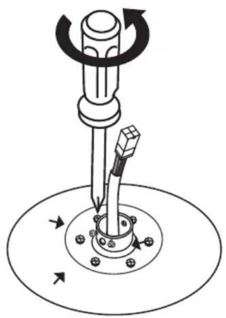
natural_image
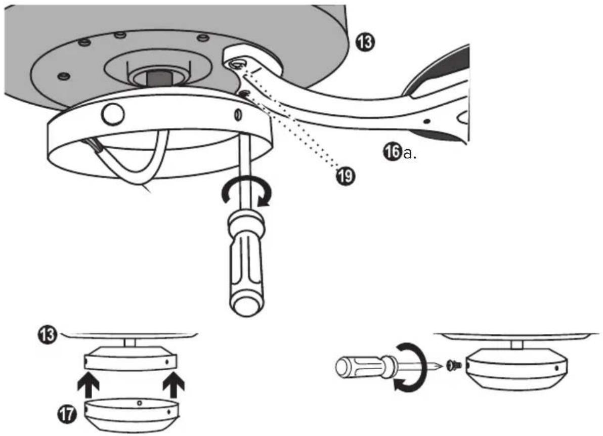
Mechanical diagram showing a screwdriver pressing a circular component with arrows indicating motion (no text or symbols)GB 1. Remove the canopy cover from the canopy.
- Unscrew 3 screws (staggered at 120^ ) from the motor at the mounting of the downrod.
text_image
Technical diagram showing mechanical assembly with numbered components and directional arrows indicating motion or assembly.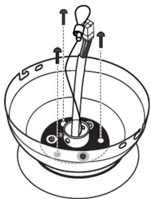
natural_image
Technical diagram of a mechanical device with rotating components and directional arrows (no text or labels)Place the mounting ring and the canopy over the down rod support so that the 3 screws on the motor protrude through the 3 larger holes in the canopy and the mounting ring.
Screw the mounting ring with canopy onto the motor with the 3 screws you removed earlier.
natural_image
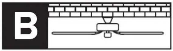
Diagram showing a mechanical assembly with a bracket and a labeled section B (no text or symbols present)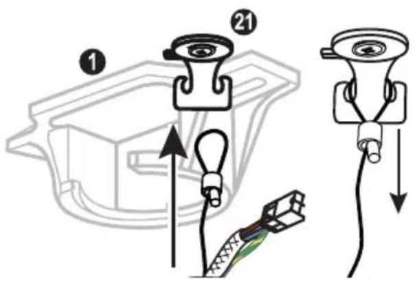
text_image
Diagram showing cable installation steps with numbered components and directional arrows indicating movementGB Hang the safety rope with the pre-assembled ceiling fan in the hook provided and tighten it.
natural_image
Line drawing of a mechanical device interacting with a bowl (no text or symbols)GB 1. Make the electrical connection as shown on page 43.
-
Slide the canopy up and twist it into the bayonet lock with the canopy screws.
-
Fasten the 4 canopy screws.
GB Connect the cables with the mains voltage to the luster terminal according to scheme ①If you want to switch an optional luminaire via a separate switch, proceed according to scheme ②
natural_image
Diagram showing a screwdriver pressing down on a curved surface with mounting holes (no text or symbols)
text_image
Diagram showing a screwdriver inserted into a mechanical component with a numbered label (13)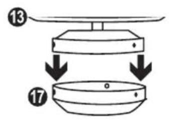
text_image
Diagram showing two labeled components (13 and 17) with arrows indicating downward motion or assembly.DE Befestigen Sie die 5 Fügelhalter jeweils mit 3 Flügelhalterschrauben an den Flügeln. Lösen Sie die Schrauben an der unteren Abdeckung un nehmen Sie diese ab.
GB Attach the 5 blade holders to the blades with 3 blade holder screws each. Loosen the screws on the bottom cover and remove it.
FR Fixez les 5 supports de pales aux pales avec 3 vis de support de pales chacun. Desserrer les vis du couvercle inférieur et le retirer.
IT Fissare i 5 supporti delle pale alle ali con 3 viti per ciascun supporto. Allentare le viti del coperchio inferiore e muoverlo.
ES Fije los 5 soportes de aspas a las aspas con 3 tornillos de soporte de aspas cada uno. Afloje los tornillos de la cubierta inferior retírela.
CZ Připevněte 5 držáků křídla k křídlům, každý se 3 šrouby držáku křídla. Uvolněte šrouby na spodním krytu sejměte jej.
NL Bevestig de 5 bladhouders aan de bladen met elk 3 bladhouderschroeven. Draai de schroeven van het onderste afdekking losen verwijder het.
PL Przymocować 5 uchwytów łopatki do łopatek za pomocą 3 śrub uchwytu łopatki każdy. Poluzować śruby dolnej pokrywy ⑰ zdjąć ją.
text_image
Technical diagram illustrating the assembly of a mechanical component with numbered parts and directional arrows indicating motion.GB Attach the 5 blade holders to the motor with 2 blade screws each. Put on the lower cover and fix it with 3 screws. Your ceiling fan is now ready to run for the first time.
- Several ceiling fans can be connected to a single hand-held transmitter.
- If several fans within radio range are to be programmed on their own hand-held transmitters, only the fan currently to be programmed must be switched on. The same applies to reprogramming and teaching new blade sizes and numbers.
FR NOTE SUR LA TÉLÉCOMMANDE
GB Insert 1 battery type 6F22 (9V) into the transmitter of the remote control. Do not press any button yet!
text_image
Diagram showing two battery charging devices with labeled components and polarity indicatorsGB Switch on the electricity supply for the ceiling fan (fuse).
GB Within first 60 seconds after power on: Press the "OFF" button until you hear two BEEP tones until confirmed.
GB Teach-in size and number of blades
GB Within the first 120 seconds after switching on the power and inserting the battery: Press the "FAN" button until you hear 3 BEEP tones.
- The motor will now run from maximum speed to standstill. The highest level is indicated in the display of the remote control. - At the end of the teach-in procedure, another 3 BEEP tones will sound for confirmation. Your ceiling fan is now ready for operation.
GB Press the "FAN" button to start the fan on low speed.
natural_image
Simple diagram showing a cross-shaped symbol with an arrow and a curved line below, no text or labels present.GB Pressing the "FAN" button again will switch the fan motor one step faster.
natural_image
Pure diagram of a cross-shaped structure with an arrow and curved base, no text or symbols present.GB Press the "F/R" button to change the direction of rotation.
GB While the motor is running, press the button to set the shutdown timer. When the set time has elapsed, the fan switches off.
text_image
Diagram showing hand holding a circular object and a control panel with a cross, clock, and arc symbolsGB Each press on this button increases the time of the shutdown timer by one hour.
natural_image
Simple line drawing of a hand holding a circular object (no text or symbols)GB Press the "OFF" button to turn off the ceiling fan.
text_image
en. OFF isNOTE: The luminaire is optional and is not supplied with your ceiling fan.
natural_image
Simple diagram with a windmill symbol above an arc and a vertical scale bar (no text or labels)natural_image
Simple diagram with a cross-shaped symbol above an arc and a vertical bar, no text or labels present.GB Press the "LIGHT" button again to turn off the optional light kit.
| GB NOTES FOR REMOVING FAULTS | |
| Fault Remedy | |
| The fan does not start | - Check the fuses/trips at the main box and other connections.- Check the fan connection to the mains.- Repeat coding of the fan with the handheld transmitter.- Replace the battery in the handheld transmitter if necessary. |
| The fan is noisy - | Check that all bolts and screws have been tightened.- Run in the fan and the bearings for 24 hours. Most noises disappear after this time. |
| The fan vibrates too much | - All screws during assembly of the ventilator, especially those relating to the axis, have an important function. Not tightened screws are the main cause of imbalances. Please make sure that all screws are tightened.- All blades have been weighed and grouped according to weight. Wood is a natural material. Their density can vary and therefore cause vibration even when all blades are of the same weight. If the blade screws of one of the blades are not tightened properly, this could cause massive wobbling.NOTE: Movement of up to 10 mm is quite acceptable and does not mean a faulty ceiling fan.- Check that the hanger bracket is firmly anchored to the ceiling. |
| Important:Opening up and repairing the unit may only be carried out by a qualified electrician! | |
CLEANING/MAINTENANCE

WARNING: Danger of electric shock! Turn off the electricity at the fuse box or circuit breaker before cleaning or servicing your fan.
- Never use water for cleaning your ceiling fan. The appliance must not get wet.
- Do not use petrol or any similar light flammable detergents!
- Clean the surface of the housing and the blades with a dry cleaning cloth.
Regular check
- Check once a year all the screws, especially those of the ceiling suspension, for tightness, retighten if necessary.
- Check electrical connections for proper connection.
Lock protection: The EC/DC motor has a built-in safety feature against blade or motor obstruction during operation. If something obstructs the fan blades or motor, the motor will keep trying to run and then stop operation after about 30 seconds of interruption. Please remove obstacles and reset.
To reset: Turn the fan off by remote transmitter. Turn the fan on again after 10 seconds. Over load protection (current limit): The device will limit the maximum current output from the receiver/drive if the fan load has increased abnormally.
Tips
- If your fan is operates automatically after installation and power on, it is because your fan has memorized the previous factory setting. Use the Universal Mode or the learning function and your fan will be ready for use.
- If the fan or light isn't working, reset power (turn the power off for at least 10 seconds and then turn the power back on) and redo the learn function setting.
- It is not possible to remotely operate more than one fan in the same room (in the area where the remote signal can reach to) if they share the same power supply. Separate power supplies (such as using individual wall switches for each fan) is required if you want to separately control more than one fan in same room.
- When the fan is turned on or operated using forward/reverse function, it shutters & goes back & forth until it turns. This is normal and it will take a few seconds to run this operation.
The packaging is made of environmentally friendly materials that you can dispose of at local recycling points.

The labelling of packaging materials helps with waste separation, these are marked with abbreviations (a) and numbers (b). These have the following meaning: 1 - 6 = plastics / 20 - 22 = paper and cardboard / 80 - 99 = composites.

The product and packaging materials are recyclable, dispose of them separately for better waste treatment. The Triman logo is only valid for France.

Do not throw electrical appliances and portable batteries in the household waste!
According to the European Directive 2012/19/EU on waste electrical and electronic equipment and its implementation in national law, used electrical equipment and waste batteries must be collected separately and recycled in an environmentally sound manner.
In the interest of environmental protection, do not dispose of the product in household waste, but recycle it properly. You can obtain information about collection points from your specialist dealer or your local administration.
FR MISE AU REBUT
EU Declaration of Conformity
Wir, die Firma
CasaFan GmbH
We, the company Senefelderstr. 8
Hasselroth, 63594, Germany
declare under our sole responsibility that the following product
Geräteart/ type of product:
Deckenventilator / ceiling fan
Handelsmarke/ trademark:
CasaFan
meets the essential requirements of the following EU-Directives:
2014/53/EC Radio Equipment Directive [OJEU L153/62-106, 22.05.2014]
2011/65/EC Directive on the restriction of the use of certain hazardous substances in electrical and electronic equipment [OJEU L174/88-110, 01.07.2011]
2009/125/EC Ecodesign directive [OJEU L285/10-35, 31.10.2009]
Authorized person for technical documentation:
natural_image
Simple line drawing of a bowl-shaped object with a lid (no text or symbols)CasaFan reserves the right to make any changes to the product without prior notice.