VIPNX - Industrial wiper Videotec - Free user manual and instructions
Find the device manual for free VIPNX Videotec in PDF.

| Product Type | Industrial Wiper Kit |
| Brand | Videotec |
| Model | VIPNX |
| Wiper Blade and Body Material | Stainless Steel AISI 316L |
| Supply Voltage | 24 Vac or 230 Vac (depending on model) |
| Frequency | 50/60 Hz |
| Current Consumption | 290 mA max (24 Vac) / 30 mA max (230 Vac) |
| Connector | 3+1 contacts (3+PE) |
| Protection Rating | IP66 |
| Certifications | CE, EAC, Lloyd's Register Marine Type Approval (codes VIPNX1C, VIPNX2C) |
| Dimensions (L x W x H) | 226 x 100 x 191 mm |
| Compatibility | NXM36 series enclosures |
| Functions | Automatic wiping with return to rest position; continuous operation via button |
| Installation | Mounting on enclosure using a metal clamp |
| Kit Contents | Wiper kit, instruction manual |
| Safety | Disconnect power before intervention; installation and maintenance by qualified personnel |
| Spare Parts | Use only original parts |
| Operating Temperature | Above 0°C (do not use below or in presence of ice) |
Frequently Asked Questions - VIPNX Videotec
User questions about VIPNX Videotec
0 question about this device. Answer the ones you know or ask your own.
Ask a new question about this device
Download the instructions for your Industrial wiper in PDF format for free! Find your manual VIPNX - Videotec and take your electronic device back in hand. On this page are published all the documents necessary for the use of your device. VIPNX by Videotec.
USER MANUAL VIPNX Videotec
natural_image
Technical line drawing of a mechanical device with lever and mounting bracket (no text or symbols)EN English - Instruction manual
IT Italiano - Manuale di istruzioni
FR Français - Manuel d'instructions
DE Deutsch - Bedienungsanleitung
RU Русский - Руководство по эксплуатации
1 About this manual
Read all the documentation supplied carefully before installing and using this product. Keep the manual in a convenient place for future reference.
1.1 Typographical conventions

CAUTION!
Medium level hazard.
This operation is very important for the system to function properly. Please read the procedure described very carefully and carry it out as instructed.

INFO
Description of system specifications.
We recommend reading this part carefully in order to understand the subsequent stages.
2 Notes on copyright and information on trademarks
The mentioned names of products or companies are trademarks or registered trademarks.
3 Safety rules

CAUTION! Device installation and maintaining must be performed by specialist technical staff only.
- The manufacturer declines all responsibility for any damage caused by an improper use of the appliances mentioned in this manual. Furthermore, the manufacturer reserves the right to modify its contents without any prior notice. The documentation contained in this manual has been collected and verified with great care. The manufacturer, however, cannot take any liability for its use. The same thing can be said for any person or company involved in the creation and production of this manual.
- Before starting any operation, make sure the power supply is disconnected.
- Be careful not to use cables that seem worn or old.
- Never, under any circumstances, make any changes or connections that are not shown in this handbook. Improper use of the appliance can cause serious hazards, risking the safety of personnel and of the installation.
- Use only original spare parts. Non-original spare parts could cause fire, electrical discharge or other hazards.
- Before proceeding with installation, check the supplied material to make sure it corresponds to the order specification by examining the identification labels (4.2 Product marking label, page 2).
4 Identification
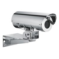
4.1 Product description and type designation
Wiper kit which can be directly installed on the housing body. Brush and body in steel. Integrates the support for the wash injector coming from the pump. Available for housings in the NXM36 series.
4.2 Product marking label
Check the label on the product packaging.
5 Preparing the product for use

Any change that is not expressly approved by the manufacturer will invalidate the warranty.
5.1 Unpacking
When the product is delivered, make sure that the package is intact and that there are no signs that it has been dropped or scratched.
If there are obvious signs of damage, contact the supplier immediately.
When returning a faulty product we recommend using the original packaging for shipping.
Keep the packaging in case you need to send the product for repairs.
5.2 Contents
Check the contents to make sure they correspond with the list of materials as below:
- Wiper kit
- Instruction manual
5.3 Safely disposing of packaging material
The packaging material can all be recycled. The installer technician will be responsible for separating the material for disposal, and in any case for compliance with the legislation in force where the device is to be used.
6 Installation

Before starting any operation, make sure the power supply is disconnected.

CAUTION! Device installation and maintaining must be performed by specialist technical staff only.
6.4 Installing the wiper kit on NXM36 housing
Insert the open metal fastening band through the 2 slots on the wiper body as shown in the drawing.
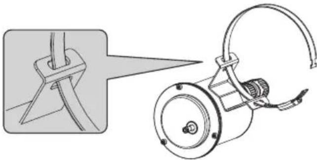
natural_image
Technical illustration of a mechanical device with a close-up view showing a component being inserted (no text or symbols present)Fig. 1
Position the wiper body by passing the clip around the body of the housing.
Tighten the clip with a screwdriver, fastening the wiper body.
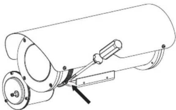
natural_image
Technical line drawing of a mechanical assembly with a cylindrical component and mounting flange (no text or symbols)Fig. 2
Assemble the wiper blade on the output shaft, fastening it in the stand-by position on the left of the front glass.
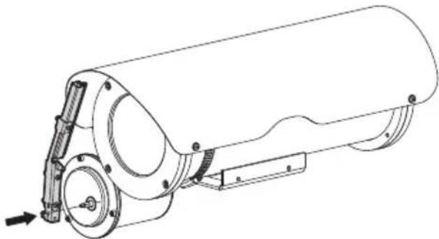
natural_image
Technical line drawing of a cylindrical mechanical device with mounting flanges and a side-mounted bracket (no text or symbols)Fig. 3
If necessary, use the fixing clip to adjust the position of the wiper body so it does not interfere with the housing support. Assembly is flexible based on the orientation of the housing.

Pay attention to adjust the wiper blade in the housing NXM36. Blade movement must not interfere with the screw heads.
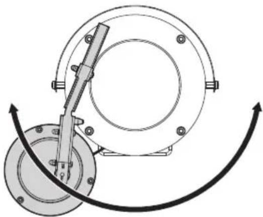
natural_image
Mechanical assembly diagram showing a rotating component with a tool and curved motion arrows (no text or symbols)Fig. 4
6.5 Wiring
Pay attention the power supply voltage used is that indicated on the plate on the back of the equipment. Electrically connect the female connector 3+PE as in the wiring diagram.
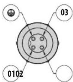
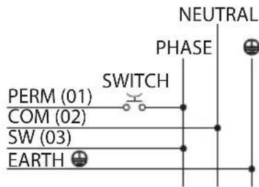
Fig. 5
Power the wiper by connecting the phase to terminal 03 (SW) of the connector, the neutral to terminal 02 (COM) of the connector and the earthing to the EARTH terminal.
Using an outer button, connect the phase to terminal 01 (PERM) of the connector.
Having pressed the outer button, continuous (permanent) functioning of the wiper is obtained. Releasing the button, the blade on the wiper goes to the stand-by position on the left of the housing glass.
If a receiver is used, connect terminal 03 of the connector to the SW output of the receiver, 01 to PERM and 02 to COM.
Connect the water supply system tube to the sprayer nozzle of the wiper blade and fasten it with the plastic clip supplied.
7 Instructions for normal operation

Do not use the wiper if the ambient temperature is under 0^ C or if there is ice.
8 Information on disposal and recycling
The European Directive 2012/19/EU on Waste Electrical and Electronic Equipment (WEEE) mandates that these devices should not be disposed of in the normal flow of municipal solid waste, but they should be collected separately in order to optimize the recovery stream and recycling of the materials that they contain and to reduce the impact on human health and the environment due to the presence of potentially hazardous substances.
The symbol of the crossed out bin is marked on all products to remember this.
The waste may be delivered to appropriate collection centers, or may be delivered free of charge to the distributor where you purchased the equipment at the time of purchase of a new equivalent or without obligation to a new purchase for equipment with size smaller than 25cm (9.8in).
For more information on proper disposal of these devices, you can contact the responsible public service.
9 Technical data
9.1 Mechanical
Wiperblade and enclosure constructed from AISI 316L stainless steel
Dimensions (∅xL): 100x169mm (3.9x6.7in) (not comprehensive of blade)
Unit weight: 1.7kg (3.7lb)
9.2 Electrical
Connector 3+1 pins
Supply voltage/Current consumption:
• 24Vac, 290mA max, 50/60Hz
• 230Vac, 30mA max, 50/60Hz
9.3 Certifications
CE listed
IP protection degree (EN60529):
• IP66
EAC certification
Lloyd's Register Marine Type Approval (certification only valid for the codes: VIPNX1C, VIPNX2C)
10 Technical drawings

The indicated measurements are expressed in millimetres.
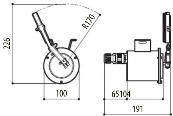
Fig. 6 VIPNX.
natural_image
Technical illustration of a mechanical device with a close-up view showing a bracket and cable assembly (no text or symbols)Fig. 1
natural_image
Technical line drawing of a cylindrical mechanical device with mounting flanges and a lever mechanism (no text or symbols)Fig. 2
natural_image
Technical line drawing of a cylindrical mechanical device with mounting flanges and a side-mounted bracket (no text or symbols)Fig. 3
natural_image
Mechanical assembly diagram showing a rotating component with a tool and curved motion arrows (no text or symbols)Fig. 4
6.5 Cablaggio
natural_image
Technical illustration of a mechanical device with a close-up view showing a bracket and cable assembly (no text or symbols)Fig. 1
natural_image
Technical line drawing of a mechanical device with mounting flanges and a lever mechanism (no text or symbols)Fig. 2
natural_image
Technical line drawing of a cylindrical mechanical device with mounting flanges and a side-mounted bracket (no text or symbols)Fig. 3
natural_image
Mechanical assembly diagram showing a rotating component with a lever mechanism (no text or labels)Fig. 4
6.5 Câblage
Dimensions (∅xL): 100x169mm (sans balai)
Poids net: 1.7kg
9.2 Électrique
natural_image
Technical illustration of a mechanical device with a close-up view showing a pin and cable assembly (no text or symbols)Abb. 1
natural_image
Technical line drawing of a mechanical assembly with a cylindrical component and mounting bracket (no text or symbols)Abb. 2
natural_image
Technical line drawing of a cylindrical mechanical device with mounting flanges and a side-mounted bracket (no text or symbols)Abb. 3
natural_image
Mechanical assembly diagram showing a rotating flange and connecting rod (no text or symbols)Abb. 4
6.5 Verkabelung
natural_image
Technical illustration of a mechanical device with a close-up view showing a component detail (no text or symbols present)Рис. 1
natural_image
Technical line drawing of a cylindrical mechanical device with mounting flanges and a lever mechanism (no text or symbols)Рис. 2
natural_image
Technical line drawing of a cylindrical mechanical device with mounting flanges and a side-mounted bracket (no text or symbols)Рис. 3
natural_image
Mechanical assembly diagram showing a rotating component with a tool and curved motion arrows (no text or symbols)Рис. 4

Headquarters Italy VIDEOTEC s.r.l.
Via Friuli, 6 - I-36015 Schio (VI) - Italy
Tel. +39 0445 697411 - Fax +39 0445 697414
Email: info@videotec.com
www.videotec.com