NEXYA S5 E DUCT - Air Conditioning OLIMPIA SPLENDID - Free user manual and instructions
Find the device manual for free NEXYA S5 E DUCT OLIMPIA SPLENDID in PDF.
Download the instructions for your Air Conditioning in PDF format for free! Find your manual NEXYA S5 E DUCT - OLIMPIA SPLENDID and take your electronic device back in hand. On this page are published all the documents necessary for the use of your device. NEXYA S5 E DUCT by OLIMPIA SPLENDID.
USER MANUAL NEXYA S5 E DUCT OLIMPIA SPLENDID
1. The appliance contains R32 gas (A2L ammability classication)
2. Comply with current regulations (e.g. the national gas standard)
3. Take care as R32 refrigerant is odourless
4. Pay attention to the fact that appliances with inammable refrigerant gas cannot be installed in small rooms.
The dimensions accepted for the room depend on the height of installation of the appliance with respect to the oor and the total amount of refrigerant gas. For details, refer to the relative table in the manual.
5. The appliance may be used by children over 8 years of age and by persons with reduced physical, sensorial
or mental capacities, or without the required experience or knowledge, provided they are supervised or have been instructed in the safe use of the appliance and understand the hazards involved.
6. Children must not play with the equipment.
7. Children must not be allowed to clean the appliance or perform user maintenance without proper supervi-
8. If the power cable is damaged, it must be replaced by the manufacturer or by its technical support service
or by similarly qualied personnel, to prevent any risk to the user.
9. Installation, initial start-up and subsequent maintenance, with the exception of the ambient air lter cleaning
and washing, must be carried out solely by authorized and qualied personnel.
10. To prevent the risk of an electric shock it is mandatory to switch o the main switch before performing the
electrical connections or any maintenance operation to the appliances.
11. During installation, comply with the minimum clearances shown in gure
12. During the appliance electrical connection, following the indications shown in gure.
13. Do not use means to accelerate the defrosting process or to clean, other than those recommended by the
14. The appliance shall be stored in a room without continuously operating ignition sources for example: open
ames, an operating gas appliance or an operating electric heater.
17. DO NOT reuse previously used joints.
adeguate a gas inammabile.
4. Remove PVC tape from ends of pipe when
ready to perform flaring work.
5. Clamp flare form on the end of the pipe. The
end of the pipe must extend beyond the flare form. Flare formPipe6. Place flaring tool onto the form.
7. Turn the handle of the flaring tool
clockwise until the pipe is fully flared. Flare the pipe in accordance with the dimensions . PIPING EXTENSION BEYOND FLARE FORM
8. Remove the flaring tool and flare form,
then inspect the end of the pipe for cracks and even flaring. Pipe gauge Tightening torqueFlare dimension (A) (Unit: mm/Inch)Flare shape Min. Max. Ø 6.4R0.4~0.845°±290° ±4AØ 9.5Ø 12.7Ø 15.9Ø 19.1Ø 2265-67 N.m (663-683 kgf.cm)23.2/0.91 23.7/0.9375-85N.m (765-867 kgf.cm)26.4/1.04 26.9/1.0618-20 N.m (183-204 kgf.cm)8.4/0.33 8.7/0.3425-26 N.m (255-265 kgf.cm)13.2/0.52 13.5/0.5335-36 N.m (357-367 kgf.cm)16.2/0.64 16.5/0.6545-47 N.m (459-480 kgf.cm)19.2/0.76 19.7/0.78 Step 4: Connect pipes Connect the copper pipes to the indoor unit first, then connect it to the outdoor unit. You should first connect the low-pressure pipe, then the high-pressure pipe.
1. When connecting the flare nuts, apply a thin
coat of refrigeration oil to the flared ends of the pipes.
2. Align the center of the two pipes that you will
connect. Indoor unit tubingFlare nutPipe
3. Tighten the flare nut as tightly as possible
wrench to tighten the flare nut according to the torque values in above table. NOTE: Use both a spanner and a torque wrench when connecting or disconnecting pipes to/from the unit. CAUTION• Ensure to wrap insulation around the piping. Direct contact with the bare piping may result in burns or frostbite.
- Make sure the pipe is properly connected. Over tightening may damage the bell mouth and under tightening may lead to leakage. Refrigerant Piping Connection Misure di sicurezza
or or 1(L) 2(N) 3(S) 1(L) 2(N) 3(S) 1(L) 2(N) 3(S) 1(L) 2(N) 3(S) QUADRIPENTAIT - 26
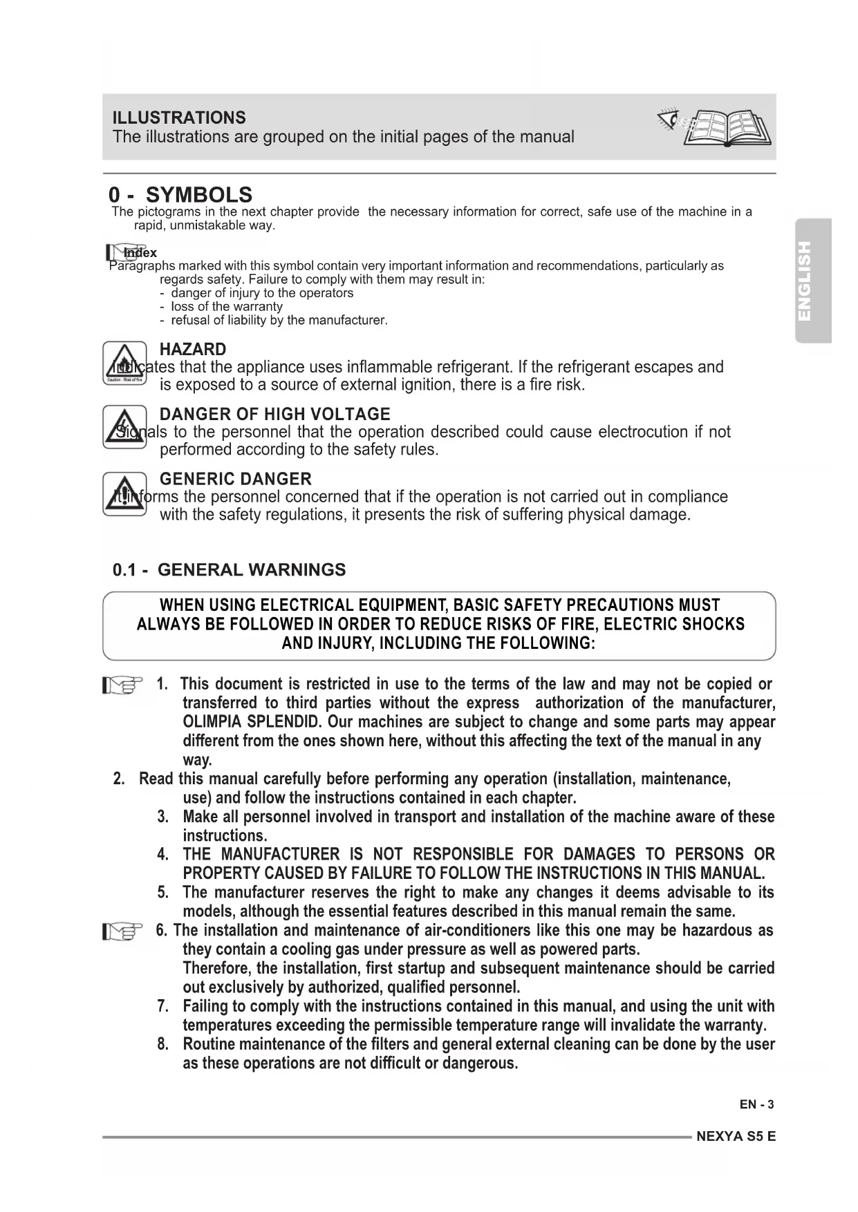
The pictograms in the next chapter provide the necessary information for correct, safe use of the machine in a rapid, unmistakable way. Index Paragraphs marked with this symbol contain very important information and recommendations, particularly as regards safety. Failure to comply with them may result in: - danger of injury to the operators - loss of the warranty - refusal of liability by the manufacturer. HAZARD Indicates that the appliance uses inammable refrigerant. If the refrigerant escapes and is exposed to a source of external ignition, there is a re risk.
DANGER OF HIGH VOLTAGE
Signals to the personnel that the operation described could cause electrocution if not performed according to the safety rules.
GENERIC DANGER It informs the personnel concerned that if the operation is not carried out in compliance with the safety regulations, it presents the risk of suffering physical damage.
0.1 - GENERAL WARNINGS
1. This document is restricted in use to the terms of the law and may not be copied or
transferred to third parties without the express authorization of the manufacturer, OLIMPIA SPLENDID. Our machines are subject to change and some parts may appear dierent from the ones shown here, without this aecting the text of the manual in any way.
2. Read this manual carefully before performing any operation (installation, maintenance,
use) and follow the instructions contained in each chapter.
3. Make all personnel involved in transport and installation of the machine aware of these
4. THE MANUFACTURER IS NOT RESPONSIBLE FOR DAMAGES TO PERSONS OR
PROPERTY CAUSED BY FAILURE TO FOLLOW THE INSTRUCTIONS IN THIS MANUAL.
5. The manufacturer reserves the right to make any changes it deems advisable to its
models, although the essential features described in this manual remain the same.
6. The installation and maintenance of air-conditioners like this one may be hazardous as
they contain a cooling gas under pressure as well as powered parts. Therefore, the installation, rst startup and subsequent maintenance should be carried out exclusively by authorized, qualied personnel.
7. Failing to comply with the instructions contained in this manual, and using the unit with
temperatures exceeding the permissible temperature range will invalidate the warranty.
8. Routine maintenance of the lters and general external cleaning can be done by the user
as these operations are not dicult or dangerous. WHEN USING ELECTRICAL EQUIPMENT, BASIC SAFETY PRECAUTIONS MUST ALWAYS BE FOLLOWED IN ORDER TO REDUCE RISKS OF FIRE, ELECTRIC SHOCKS AND INJURY, INCLUDING THE FOLLOWING: ILLUSTRATIONS The illustrations are grouped on the initial pages of the manualENGLISH EN - 4
9. During installation and maintenance, respect the precautions indicated in the manual,
and on the labels applied inside the units, as well as all the precautions suggested by good sense and by the safety regulations in eect in your country.
10. Perform installation and maintenance using equipment that is suitable for
11. Always wear gloves and protective goggles when performing any operations on the
refrigerating side of the units.
12. Air conditioners must not be installed in places containing inammable gasses, explosive
gasses, or in very humid environments (laundries, greenhouses, etc.), or in places where there are machines that generate very great heat.
13. In case of replacement of parts, use only original OLIMPIA SPLENDID parts.
To prevent any risk of electrocution, always disconnect the main circuit breaker before making electric connections or performing any maintenance on the units.
15. Lightening, cars in the vicinity and mobile phones can cause malfunctioning. Disconnect
the unit electrically for a few seconds and then re-start the air conditioner.
16. On rainy days, it is recommended to connect the electric power supply in order to prevent
damage caused by lightening.
17. If the unit is unused for a long period, or no-one uses the climate-controlled room, it is
recommended to disconnect the electric power supply in order to prevent accidents.
18. Do not use liquid or corrosive detergents to clean the unit, do not spray water or other
liquids onto the unit, since they could damage the plastic components or even cause electric shocks.
19. Do not wet the indoor unit and the remote control.
20. In the event of operating anomalies (e.g. strange noise, bad odour, smoke, abnormal
temperature rise, electric dispersions, etc.) disconnect the electric power supply immediately. Contact the local dealer.
21. Do not let the air conditioner run for a long time when the humidity is very high and a door
or a windows is left open. Moisture may condense and wet or damage furniture.
22. Do not plug or unplug the power supply plug during operation.
Fire and electric shocks risk.
23. Do not touch (operation) the product with wet hands.
Fire and electric shocks risk.
24. Do not place a heater or other appliance near the power cable. Fire and electric shocks
25. Make sure water does not enter the electrical parts.
It could cause res, product failure or electric shocks.
26. Do not open the air inlet grid during appliance operation. Risk of injury, electric shock or
damage to the product.
27. Do not block the air inlet or outlet; the product could be damaged.
28. Do not insert hands or other object through air inlet or outlet while the product is operated.
The presence of sharp and moving parts could cause injury.NEXYA S5 E ENGLISH EN - 5
29. Do not drink the water drained from the product.
It is not sanitary could cause serious health issues.
30. When there are gas leaks from other units, ventilate the room well before activating the
32. Ventilate the room well when used together with a stove, etc.
33. Do not use for special purposes.
34. The persons that work or intervene on a cooling circuit, must be in possession of suitable
certication, issued by an accredited assessment body. This must attest skill in safely handling refrigerants in compliance with assessment specication acknowledged by sector associations.
35. Do not emit R32 gas into the atmosphere; R32 is a uorinated greenhouse gas with a
Global Warming Potential (GWP) = 675.
36. The appliances described in this manual are in compliance with the applicable European
Directives and successive amendments.
37. The appliance contains A2L inammable gas. For the correct mode of installation,
please consult this manual.
- This climate control appliance contains uorinated gas. For specic information regarding the type and quantity of gas, refer to the data plate axed to the unit.
- The installation, assistance, maintenance and repair of the appliance, must be performed by a qualied certied technician.
- Product removal and re-cycling operations must be performed by a qualied certied technician.
- If the system has a leak-detection device installed, the checks for leaks must be performed at least every 12 months.
- When the unit is checked for leaks, keeping a record of all inspections is highly recommended.
- Before starting to operate on the appliance, it is necessary to check the zone surrounding the equipment to make sure there are no dangers of re nor risks of combustion. To repair the refrigerating system, it is necessary to take the following precautions before starting the intervention on the system.
1. The zone MUST be checked with a specic refrigerating liquids detector before and
during work, so that the technician is aware of potentially ammable atmospheres. Make sure the detection device of the leaks is suitable for use with ammable refrigerants, then that it does not produce sparks and that is adequately sealed or intrinsically safe.
2. The leakage electronic detectors may need calibration.
If necessary, calibrate them in a zone free of refrigerant.
3. Make sure the detector is not a potential source of combustion and that it is suitable
for the refrigerant used. The device for detection must be set at a percentage of the refrigerant LFL and must be calibrated for the used refrigerant; the appropriate percentage of gas (maximum 25 %) must be conrmed. 3a. The leakage detection uids are suitable for most of the refrigerants. The detergents containing chlorine MUST be avoided. Danger of corrosion of the copper pipes.
4. If the presence of a leak is suspected, all open ames must be removed.
5. All sources of combustion (even a lit cigarette) should be kept away from the place
in which all operations during which the ammable refrigerant may be released in the surrounding space must be carried out.ENGLISH EN - 6
6. Make sure the area is adequately ventilated before intervening inside the system; a
continuous degree of ventilation must be present.
7. Before any operation, always check that:
- the condensers are unloaded. The operation must be carried out safely to avoid the risk of producing sparks;
- there are no live electrical components and that the cables are not exposed while loading, recovering or bleeding the system;
- there is continuity in the ground connection.
8. Periodically check that the cables are not subject to wear, corrosion, excessive
pressure, vibrations, sharp edges or any other hostile environmental situation.
9. When intervening inside the refrigerating circuit to carry out repairs or for any other
reason, the conventional procedures must be followed:
- remove the refrigerant;
- bleed the circuit with an inert gas;
- bleed again with an inert gas;
- open the circuit by cutting or by means of brazing. 9a. Oxygen-Free Nitrogen (OFN) MUST be purged through the system both before and during the brazing process. 9b. When the nal OFN charge is used, the system must be discharged up to atmospheric pressure to allow the execution of the work. This operation is absolutely essential if it is desired to carry out brazing operations on the pipes.
10. The load of refrigerant must be stored in the specic custody cylinders. The system
must “cleaned” with OFN to make the unit safe. It may be necessary to repeat this process several times. DO NOT use compressed air or oxygen for this operation. 10a. Make sure that contamination between dierent refrigerants does NOT occur when a reloading equipment is used. The exible pipes or ducts MUST be as short as possible to reduce the quantity of refrigerant inside them to a minimum.
11. The cylinders must be kept in vertical position.
Only use cylinders suitable for collection of refrigerants. The cylinders must be complete of a pressure-relief valve and switch o valves in good conditions. A set of calibrated weighing scales must also be available.
12. The pipes must be equipped with couplings for disconnection and must NOT
present leaks. Before using the collection machine, check that it underwent correct maintenance and that the possible associated electric components are sealed, to prevent switching on in case of leak of refrigerant.
13. Make sure the refrigerating system is earthed before proceeding with reloading of
the system with refrigerant. Label the system when reloading is complete. Pay particular attention not to overload the refrigerating system.
14. Before proceeding with reloading, the system must undergo the pressure test with
OFN and the tightness test at the end of reloading, but before commissioning. It is necessary to carry out an additional tightness test before leaving the site. 14a. Remove the refrigerant safely. Move the refrigerant in the cylinders suitable for recovery. Make sure there is a correct number of cylinders to contain the charge entirely. All cylinders are labelled for this type of refrigerant (special cylinders for refrigerant recovery). The cylinders must be complete of a pressure relief valve and of and of the corresponding closure valve in good conditions. Empty cylinders are evacuated and, if possible, cooled down before recovery. 14b.Equipment for recovery must be within the range of the technician, in good conditions, with a series of instructions and must be suitable for recovery of all the refrigerants (even ammable ones). A series of calibrates scales must be available and in good conditions. Check that the pipes are in good conditions and complete of disconnection joints without losses. 14c. Before using the machine for recovery, check that it is in good operating conditions, that it has been adequately maintained and that all the associated electric components are sealed to prevent switching-in in case of release of refrigerant. In case of doubt,NEXYA S5 E ENGLISH EN - 7 please contact the manufacturer.
15. Collected refrigerant must be returned to the uid supplier in the appropriate
collection cylinder, compiling the corresponding Handover Note of Scraps. DO NOT mix the refrigerants in the collection units and, in particular, in the cylinders.
16. Make sure that contamination between dierent refrigerants does not occur when
a reloading equipment is used. The exible pipes or ducts must be as short as possible to reduce the quantity of refrigerant inside them to a minimum.
17. Do not drill nor burn the unit.
18. The replaced electric components MUST be suitable and correspond to the appliance
specications. Every maintenance operation MUST be carried out as described in this manual. Contact the manufacturer in case of doubt.
19. Apply the following checks:
The size of the room inside which are located the parts containing the refrigerant, are in accordance with the current quantity of charge of the refrigerant;
- The ventilation device works correctly and the outlets are not clogged;
The markings on the machine must always be visible and readable, correct them if not;
- The pipelines ore the components containing refrigerant MUST be installed in a place where no substance may corrode them, unless the components are built with materials intrinsically resistant against corrosion or are suitably protected against this risk.
20. The refrigerating gases are odourless.
21. For disposal and marking (through signs) of the appliance containing refrigerant
gas, please refer to the local regulations.
22. To store the appliance: The packaging for storage must be resistant in order to
avoid that the appliance may take damage and to avoid the possible leakage of refrigerant gas.
23. Recovered refrigerant must not be discharged in another refrigerating system
unless it has been cleaned and checked.
24. Dismantling MUST be carried out by a qualied technician whom MUST use the PPE
correctly and MUST perfectly know the equipment. All the refrigerants MUST be recovered safely; always collect a sample of oil and refrigerant before emptying the circuit.
25. Before starting any dismantling operation:
- Electrically insulate the system. - Ensure that you have mechanical handling equipment at your disposal to handle the tanks, if necessary. - The equipment and recovery tanks MUST be in compliance with the standards.
26. The equipment must be labelled indicating that it has been deactivated and emptied
of refrigerant. The label must be dated and signed. Make sure that on the equipment are present labels indicating that the equipment contains ammable refrigerant.
27. If the compressors or compressor oils must be removed, it is necessary to check
that they have been extracted safely and at an acceptable level to ensure that the ammable refrigerant has not remained inside the lubricant. The evacuation process must be carried out before returning the compressor to the suppliers. To speed up this process, only electric heating of the compressor body must be used.
The air-conditioner should be used for the exclusive purpose of producing hot or cool air (on demand) for the sole purpose of obtaining a comfortable temperature in the room.
- Improper use of the machine (outside and inside units) causing damage to persons, property or animals relieve OLIMPIA SPLENDID of any liability.
0.4 - HAZARDOUS ZONES
- The climate controllers must not be installed in environments with the presence of inammable gases, explosive gases, in very humid environments (laundries,ENGLISH EN - 8 greenhouses, etc.), or in places with other machines that generate a strong heat source, in proximity of a sources of salt water or sulphurous water.
- DO NOT use gas, gasoline or other inammable liquids near to the climate controller.
- The climate controller does not have a fan for the introduction of fresh outdoor air into the room; ventilate by opening doors and windows.
- Always install circuit breaker and a dedicated power circuit.
This product must be used exclusively according to the specications indicated in this manual. Use dierent to that specied, could cause serious injuries. THE MANUFACTURER IS NOT LIABLE FOR INJURY/DAMAGE TO PERSONS/ OBJECTS DERIVING FROM FAILURE TO COMPLY WITH THE REGULATIONS CONTAINED IN THIS MANUAL.
0.5 - FUSE SPECIFICATIONS
- The appliance is equipped with a safety fuse, the specications are printed on the board: T20A/250 VAC (for unit with <24000 Btu/h) T30A/250 VAC (for unit with >24000 Btu/h)
- For units with R32 refrigerant, only use explosion proof ceramic fuses.
0.6 - CHECKS TO PERFORM BEFORE INSTALLATION
a. Checks at the area Before starting to work on the systems containing inammable refrigerants, safety checks are necessary to reduce the risk of ignition to a minimum. To repair a refrigeration system, the following precautions must be complied with before working on the system. b. Work procedure The job must be performed according to a controlled procedure in a way to reduce the risk of the presence of inammable gas or vapour to a minimum during the performance of the job. c. General work area All maintenance personnel and those working in the local area, must be trained regarding the job performed. Do not work in tight spaces. The area around the work area must be isolated. Guarantee that the conditions inside the area are safe by verifying the inammable material. d. Check the presence of refrigerant The area must be checked using a specic refrigerant detector before, during and after the execution of the work so as to ensure that the technician is informed about the presence of possibly ammable atmospheres. Check the leak detector equipment used is suitable for use with inammable refrigerants, i.e. does not cause sparks, is suitably sealed or intrinsically safe. e. Presence of extinguishers Whenever work must be performed on the refrigeration system at high temperatures or on relative components, a suitable re-prevention system must be prepared. Position CO2 or dry powder extinguishers in proximity of the loading area. f. No source of ignition No-one working in the refrigeration systems and exposed to contact with the piping that contains or contained inammable refrigerant, must use sources of ignition in order to prevent the riskNEXYA S5 E ENGLISH EN - 9 of re or explosion. Every possible source of ignition, among which cigarette smoke, must be kept at a due distance from the place of installation, repair, removal or disposal, where there is a risk of the refrigerant liquid leaking into the surrounding space. Before performing the job, the area surrounding the appliance must be controlled in order to ascertain that there are no inammable substances or risks of ignition present. NO SMOKING signs must be displayed. g. Ventilated area Make sure that the area is open or suitably ventilated before interacting with the system or performing any operation at high temperatures. Ensure constant ventilation during the operations period. Ventilation must safely disperse all refrigerant released and, if possible, expel it outside into the atmosphere. h. Refrigeration system checks If modied, the electric components must be suitable for the purpose and compliant with the correct specications. Always follow the manufacturer’s guide lines relative to maintenance and technical after-sales assistance. If in doubt, consult the manufacturer’s technical after-sales service. The plants that use inammable refrigerants must be subjected to the following verications:
- the dimension of the load must be compliant with the chamber in which the components containing the refrigerant are installed;
- the plants and ventilation outlets must operate adequately and not be obstructed;
- if an indirect refrigeration circuit is in use, check the presence of refrigerant in the secondary circuit; the marking on the systems must be visible and legible;
- illegible markings and signs must be corrected;
- the pipe or refrigeration components must be installed in a position where it is improbable that they are exposed to substances that could corrode the components containing the refrigerant, unless the components are manufactured with intrinsically corrosion resistant materials or are appropriately protected from corrosive agents.
i. Check the electric devices
The repair and maintenance interventions of electric components must envision initial safety checks and component inspection procedures. In the case of a fault which may compromise safety, no electric power supply must be connected to the circuit until it has been suitably repaired. If the fault cannot be repaired immediately, but the operation must be continued, use a suitable temporary solution. This solution must be communicated to the owner of the plant so that all parties can be informed. The initial safety controls envision:
- draining the condensers: this operation must be performed safely to prevent the possible formation of sparks;
- no exposure of components and electric wiring to voltages during loading, repair or purication of the system;
- the continuity of the earth. l. Repair interventions of the hermetic components
- During the repair of hermetic components, all electric power supply lines must be disconnected from the appliance running, before the eventual removal of the hermetic covers, etc. Whenever it is absolutely necessary to have electric power supply for the unit during maintenance, a constantly active leak detector must be positioned in the most critical point in order to signal a potentially dangerous situation.
- Particular attention must be paid to the following to guarantee that, in the case of intervention on electric components, the housing is not altered in a way to affect the level of protection.NL
The units making up the climate control system are packaged individually in cardboard boxes. Individual unit packages can be transported by hand by two members of personnel, or loaded onto a transport trolley; up to max. three packages stacked for indoor units and individually for outdoor units. The parts indicated below are included in the supply. The other items necessary for installation must be purchased.
1. Instruction booklet
9. Battery for remote control
quantity 2 - AAA type x 1.5V This includes damage to cables, excessive number of connections, terminals not manufactured in compliance with original specications, damage to the gaskets, incorrect installation of the closing devices, etc.
- Make sure that the appliances are mounted securely.
- Make sure that the gaskets or sealing materials have not deteriorated to the point that they cannot be used to prevent the entry of inammable atmospheres. The spare components must be compliant with manufacturer specications. The use of silicone-based sealants can inhibit the efcacy of some types of leak detection equipment. Intrinsically safe components do not have to be isolated before working on them.NEXYA S5 E ENGLISH EN - 11
1.2 - MATERIAL NECESSARY NOT SUPPLIED
For correct installation of the appliance, components that have not been supplied must be used. a. Connection pipes unit (water side) b. Connection pipes unit (gas side) c. Magnetic ring
An incorrect installation may cause water leakage, electric shocks and re, or cause a mal- function of the equipment. Name of Accessories Q‘ty (pc) Shape Installation plate (some models)
Plastic expansion sheath (some models) 5-8 (depend- ing on models) Self-Tapping Screw A (some models) 5-8 (depend- ing on models) Transfer connector (packed with the indoor or outdoor unit, depending on models) NOTE: Pipe size may differ from appliance to appliance. To meet different pipe size requirements, sometimes the pipe connections need a transfer connector installed on the outdoor unit. Optional part (one piece/ one indoor unit) Optional part (1-5 pieces for outdoor unit, depending on mod- els) Name of Accessories Q‘ty (pc) Shape Drain joint (some models) 1 Seal ring (some models) 1 Magnetic ring (Hitch it on the connective cable between indoor unit and outdoor unit after installation.) (some models) Varies by model Cord protection rubber ring (If the cord clamp cannot fas- ten on a small cord, use the cord protection rubber ring [supplied with accessories] to wrap around the cord. Then x it in place with the cord clamp.) (some models)
OPTIONAL Name Forma Quantità (PC) Connecting pipe assembly. Liquid side Ø6.35 (1/4 in) Parts you must purchase separate. Ø9,52 (3/8 in) Gas side Ø9,52 (3/8 in) Ø12.7 (1/2 in) Ø 16 (5/8 in)
Store the cartons in a closed environment protected against atmospheric agents and raised off the oor by planks or a pallet. TO NOT TURN THE CARTON UPSIDE DOWN.ENGLISH EN - 12
1.5 - RECEIPT AND UNPACKING
The packaging is made up from suitable material and performed by expert personnel. The units are delivered complete and in perfect condition. However, for he quality control of the transport services, follow the warnings below: a. On receipt of the packages, check whether the packaging is damaged. If this is the case, withdraw the goods with reserve, producing photographic proof and any apparent damage. b. Unpack, checking the presence of the individual components with the packing lists. c. Control that all components have not undergone damage during transport. If this is the case, inform the carrier by registered letter with acknowledgement of receipt within 3 days of receiving the goods, presenting photographic documentation. d. Pay attention when unpacking and installing the equipment. Sharp parts can cause injury. Pay particular attention to the edges of the structure and the ns of the condenser and evaporator. e. Send the same information by fax also to OLIMPIA SPLENDID. No information concerning damage undergone can be taken into consider- ation after 3 days from delivery. For any controversy the court of jurisdiction will be BRESCIA. Keep the packaging for at least the duration of the warranty period, for any shipments to the after-sales centre for repairs. Dispose of packaging in compliance with the regulations in force regarding waste dis- posal.
The appliance must be installed, activated and kept in an environment with area exceeding X m
(see tables in paragraph 7.4). The appliance must not be installed in a non-ventilated area, whenever the surface is less than X m
(see tables in paragraph 7.4). Failure to apply the regulations indicated, which can cause unit malfunctioning, relieve OLIMPIA SPLENDID from any form of warranty and any damage/injury caused to persons, animals or objects. The electrical system must comply with the regulations and rating data in the technical sheet, with good grounding. Do not install, remove, or reinstall the unit by yourself (customer). There is risk of re, electric shock, explosion, or injury. For installation, always contact the dealer or an Authorized service centre. There is risk of re, electric shock, explosion, or injury.
Be sure the installation area does not deteriorate with age. If the base collapses, the air conditioner could fall with it, causing property damage, product failure, and personal injury.
Install the unit securely in a place which can bear the weight of the unit. Do not install the unit in a place where a ammable gas leaks. - - - - - - - - - - - - - - - - - - - - - - - - - - -NEXYA S5 E ENGLISH EN - 13 Specifications Specifications Number of units that can be used together Connected units 1-5 units Compressor stop/start frequency Stop time 3 min or more voltage uctuation ±10% of rated voltage Power source voltage voltage drop during start ±15% of rated voltage interval unbalance ±3% of rated voltage Unit: m 10m(32.8ft) When installing multiple indoor units with a single outdoor unit, ensure that the length of the refrigerant pipe and the drop height between the indoor and outdoor units meet the requirements illustrated in the following diagram: Indoor unit Indoor unit Indoor unit Outdoor unit 15m(49ft) 15m(49ft) Max.Height dierence Dual Trial Max. length for all rooms 40 60 Max. length for one indoor unit 25 30 Max. height dierent between indoor and outdoor unit
Max. height dierent between indoor units 10 10 Quadri Penta
NOTE: For the units adopt quick connectors, no more than two pipes can be connected, and the Max. length for each pipe is 7.5 meters. Specifications Specifications Number of units that can be used together Connected units 1-5 units Compressor stop/start frequency Stop time 3 min or more voltage uctuation ±10% of rated voltage Power source voltage voltage drop during start ±15% of rated voltage interval unbalance ±3% of rated voltage Unit: m 10m(32.8ft) When installing multiple indoor units with a single outdoor unit, ensure that the length of the refrigerant pipe and the drop height between the indoor and outdoor units meet the requirements illustrated in the following diagram: Indoor unit Indoor unit Indoor unit Outdoor unit 15m(49ft) 15m(49ft) Max.Height dierence Dual Trial Max. length for all rooms 40 60 Max. length for one indoor unit 25 30 Max. height dierent between indoor and outdoor unit
Max. height dierent between indoor units 10 10 Quadri Penta
NOTE: For the units adopt quick connectors, no more than two pipes can be connected, and the Max. length for each pipe is 7.5 meters.
2.2 - SPECIFICATIONS FOR INSTALLATION OF THE EXTERNAL UNIT
For the units adopt quick connectors, no more than two pipes can be connected, and the Max. length for each pipe is 7.5 meters. When installing multiple indoor units with a single outdoor unit, ensure that the length of the refrigerant pipe and the drop height between the indoor and outdoor units meet the requirements illustrated in the following diagram:L N MC MC(L1) (L2) ENGLISH EN - 14 Outdoor Unit Installation Outdoor Unit Installation evoba )ni42( mc06 60cm (24in) on right 30cm (12in) on left 200cm (79in) in fron
30cm (12in) from back wall Installation Instructions – Outdoor unit Step 1: Select installation location Before installing the outdoor unit, you must choose an appropriate location. The following are standards that will help you choose an appropriate location for the unit. Proper installation locations meet the following standards:
Meets all spatial requirements shown in Installation Space Requirements above.
Good air circulation and ventilation
Firm and solid—the location can support the unit and will not vibrate
Noise from the unit will not disturb others Install the unit by following local codes and regulations , there may be dier slightly between dierent regions.
SPECIAL CONSIDERATIONS FOR EXTREME
WEATHER If the unit is exposed to heavy wind: Install unit so that air outlet fan is at a 90° angle to the direction of the wind. If needed, build a barrier in front of the unit to protect it from extremely heavy winds. See Figures below. Strong wind Strong wind Strong wind If the unit is frequently exposed to heavy rain or snow: Build a shelter above the unit to protect it from the rain or snow. Be careful not to obstruct air flow around the unit. If the unit is frequently exposed to salty air (seaside): Use outdoor unit that is specially designed to resist corrosion. Wind Baffle
Protected from prolonged periods of direct sunlight or rain DO NOT install unit in the following locations: Near an obstacle that will block air inlets and outlets Near a public street, crowded areas, or where noise from the unit will disturb others Near animals or plants that will be harmed by hot air discharge Near any source of combustible gas In a location that is exposed to large amounts of dust In a location exposed to a excessive amounts of salty air Where snowfall is anticipated, raise the unit above the base pad to prevent ice buildup and coil damage. Mount the unit high enough to be above the average accumulated area snowfall. The minimum height must be 18 inches Outdoor Unit Installation Outdoor Unit Installation evoba )ni42( mc06 60cm (24in) on righ 30cm (12in) on left200cm (79in) in fron 30cm (12in) from back wall Installation Instructions – Outdoor unit Step 1: Select installation location Before installing the outdoor unit, you must choose an appropriate location. The following are standards that will help you choose an appropriate location for the unit. Proper installation locations meet the following standards: Meets all spatial requirements shown in Installation Space Requirements above. Good air circulation and ventilation Firm and solid—the location can support the unit and will not vibrate Noise from the unit will not disturb others Install the unit by following local codes and regulations , there may be dier slightly between dierent regions.
SPECIAL CONSIDERATIONS FOR EXTREME
WEATHER If the unit is exposed to heavy wind: Install unit so that air outlet fan is at a 90° angle to the direction of the wind. If needed, build a barrier in front of the unit to protect it from extremely heavy winds. See Figures below. Strong windStrong windStrong wind If the unit is frequently exposed to heavy rain or snow: Build a shelter above the unit to protect it from the rain or snow. Be careful not to obstruct air flow around the unit. If the unit is frequently exposed to salty air (seaside): Use outdoor unit that is specially designed to resist corrosion. Wind Baffle Protected from prolonged periods of direct sunlight or rain DO NOT install unit in the following locations: Near an obstacle that will block air inlets and outlets Near a public street, crowded areas, or where noise from the unit will disturb others Near animals or plants that will be harmed by hot air discharge Near any source of combustible gas In a location that is exposed to large amounts of dust In a location exposed to a excessive amounts of salty air Where snowfall is anticipated, raise the unit above the base pad to prevent ice buildup and coil damage. Mount the unit high enough to be above the average accumulated area snowfall. The minimum height must be 18 inches 2.3 - PROCEDURES FOR INSTALLATION OF THE EXTERNAL UNIT• Install the outdoor unit• Connect the refrigerant pipes • Connect the wires
- Evacuate the refrigeration system • Perform a test run 2.3.1 - Step 1: Select installation locationInstall the unit by following local codes and regula-tions, there may be differ slightly between different regions. Before installing the outdoor unit, you must choose an appropriate location. The following are standards that will help you choose an appropriate location for the unit.Proper installation locations meet the following stand-ards:• Keep the distances indicated in the gure.• Good air circulation and ventilation.• Stable and levelled supporting surface.• The unit noise must not disturb others.• Fixing wall able to bear the unit.
- Where snowfalls are envisaged, adopt appropriate measures to prevent ice accumulation and damages to the unit.DO NOT install unit in the following locations:• Near an obstacle which may obstruct the air inlet or outlet.• Near a public street, crowded areas, or where noise from the unit will disturb others• Near animals or plants that will be harmed by hot air discharge• Near any source of combustible gas In a location that is exposed to large amounts of dust• In a location exposed to a excessive amounts of salty air2.3.2 - Special considerations for extreme weatherIf the unit is exposed to heavy wind:Install unit so that air outlet fan is at a 90° angle to the direction of the wind. If needed, build a barrier in front of the unit to protect it from extremely heavy winds.NEXYA S5 E 946x810x410 673 403805x554x330 511 317890x673x342 663 354 Misure di sicurezza Fase 2: Installare il giunto di scarico (solo unità pompa di calore)Prima di bullonare l'unità esterna in posizione, è necessario installare il giunto di scarico nella parte inferiore dell'unità. Si noti che ci sono due diversi tipi di giunti di scarico a seconda del tipo di unità esterna. Se il giunto di scarico viene fornito con una guarnizione in gomma (vedi Fig. A), eettuare le seguenti operazioni:
ENGLISH EN - 15 Outdoor Unit Installation
In cold climates, make sure that the drain hose is as vertical as possible to ensure swift water drainage. If water drains too slowly, it can freeze in the hose and ood the unit. The outdoor unit can be anchored to the ground or to a wall-mounted bracket with bolt(M10). Prepare the installation base of the unit according to the dimensions below. Step 3: Anchor outdoor unit
UNIT MOUNTING DIMENSIONS
The following is a list of dierent outdoor unit sizes and the distance between their mounting feet. Prepare the installation base of the unit according to the dimensions below. Split Type Outdoor Unit ABDWHWH Outdoor Unit Types and Specifications Step 2: Install drain joint (Heat pump unit only) Before bolting the outdoor unit in place, you must install the drain joint at the bottom of the unit. Note that there are two dierent types of drain joints depending on the type of outdoor unit. If the drain joint comes with a rubber seal (see Fig. A ), do the following:
1. Fit the rubber seal on the end of the drain joint
that will connect to the outdoor unit.
2. Insert the drain joint into the hole in the base
3. Rotate the drain joint 90° until it clicks in place
facing the front of the unit.
4. Connect a drain hose extension (not included)
to the drain joint to redirect water from the unit during heating mode. If the drain joint doesn’t come with a rubber seal (see Fig. B ), do the following:
1. Insert the drain joint into the hole in the base
pan of the unit. The drain joint will click in place.
2. Connect a drain hose extension (not included)
to the drain joint to redirect water from the unit during heating mode. Seal Drain joint(A) (B)Base pan hole ofoutdoor unitSeal Outdoor Unit DimensionsW × H × D (mm)Mounting Dimensions (mm)Distance A Distance B If the unit is frequently exposed to heavy rain or snow: Build a shelter above the unit to protect it from the rain or snow. Be careful not to obstruct air ow around the unit. If the unit is frequently exposed to salty air (seaside): Use outdoor unit that is specially designed to resist corrosion.
2.3.3 - Step 2: Install drain joint (Heat pump unit only)
Before bolting the outdoor unit in place, you must install the drain joint at the bottom of the unit. Note that there are two different types of drain joints depending on the type of outdoor unit. If the drain joint comes with a rubber seal (see Fig. A), do the following:
1. Position the seal on the drain joint.
2. Insert the joint on the hole located on the external base
3. Turn the joint 80° until you hear the click and place it
4. Connect a drain tube to the joint (not supplied) and
direct it into a catch pit. If the drain joint doesn’t come with a rubber seal (see Fig.B), do the following:
1. Insert the joint onto the hole located on the base of the
2. Turn the joint 80° until you hear the click and position it frontally.
3. Connect a drain tube to the joint (not supplied) and direct it into a catch pit.
In cold climates, make sure the drain tube is as vertical as possible to ensure quick drainage of water. If water drains too slowly, it may freeze in the tube and damage the unit.
2.3.4 - Step 3: Anchor outdoor unit
The outdoor unit can be anchored to the ground or to a wall-mounted bracket with bolt (M10). Prepare the installation base of the unit according to the dimensions below.
2.4 - UNIT MOUNTING DIMENSIONS
The following is a list of different outdoor unit sizes and the distance between their mounting feet. Prepare the installation base of the unit according to the dimensions below.ENGLISH EN - 16 Outdoor Unit Installation Diagram Installation Diagram Installation Diagram
Installation plateMounting screw ST3.9×25-C-HRefrigerant pipe Remote controller holder Clip anchor (2) This illustration is for demonstration purposes only. The actual shape of your air condtioner may be slightly dierent. Copper lines must be independently insulated. CAUTION To prevent wall damage, use a stud nder to locate studs. A minimum pipe run of 3 metres is required to minimise vibration & excessive noise. Two of the A, B, and C air circulation pathways must be free from obstructions at all times. NOTE: The installation must be performed in accordance with the requirement of local and national standards. The installation may be slightly dierent in dierent areas. Safety Precautions
Installation plate Mounting screw ST3.9×25-C-H Clip anchor (1) Remote controller holder
The maximum amount of the connection cables is 5. This section is for reference only. Air-break SwitchDrainage Pipe Air-break SwitchOutdoor UnitPower CableMore thanMore than Dual TrialQuadriPenta Outdoor Unit Installation When Select a 24K Indoor Unit The 24K indoor unit can only be connected with an A system. If there are two 24K indoor units, they can be connected with A and B systems. Connective pipe size of an A and B system (unit: inch) Indoor Unit capacity (Btu/h) Liquid Gas 7K/9K/12K 1/4 3/8 12K/18K 1/4 1/2 24K 3/8 5/8 Notes On Drilling Hole In Wall You must drill a hole in the wall for the refrigerant piping, and the signal cable that will connect the indoor and outdoor units.
Determine the location of the wall hole based on the location of the outdoor unit.
Using a 65-mm (2.5”) core drill, drill a hole in the wall. NOTE: When drilling the wall hole, make sure to avoid wires, plumbing, and other sensitive components.
300 cm / 118” or more 60 cm / 23.6” or more150 cm / 59” or more25 cm / 9.8” or more25 cm / 9.8” or more890x673x342 (35.0”x 26.5”x 13.5”)663 (26.1”)354 (13.9”) The relations between H, A and L are as follows.2.5 - INSTALLATION DIAGRAM
- To prevent wall damage, use a stud nder to locate studs. • A minimum pipe run of 3 metres is required to minimise vibration & ex- cessive noise.
- Two of the A, B, and C air circulation pathways must be free from obstruc-tions at all times. • This illustration is for demonstration purposes only. • The actual shape of your air conditioner may be slightly different.
- Copper lines must be independently insulated. The installation must be performed in ac- cordance with the requirement of local and national standards. The installation may be slightly different in different areas.NEXYA S5 E Misure di sicurezza (unità: mm/inch) Dimensioni dell’unità esterna W × H × DDimensioni di montaggio Distanza A Distanza B 760x590x285 (29,9x23,2x11,2) 530 (20,85) 290 (11,4) 810x558x310 (31,9x22x12.2) 549 (21,6) 325 (12,8) 845x700x320 (33,27x27,5x12,6) 560 (22) 335 (13,2) 900x860x315 (35,4x33,85x12,4) 590 (23,2) 333 (13,1) 945x810x395 (37,2x31,9x15,55) 640 (25,2) 405 (15,95) 990x965x345 (38,98x38x13,58) 624 (24,58) 366 (14,4) 938x1369x392 (36,93x53,9x15,43) 634 (24,96) 404 (15,9) 900x1170x350 (35,4x46x13,8) 590 (23,2) 378 (14,88) 800x554x333 (31,5x21,8x13,1) 514 (20,24) 340 (13,39) 845x702x363 (33,27x27,6x14,3) 540 (21,26) 350 (13,8) 946x810x420 (37,2x31,9x16,53) 673 (26,5) 403 (15,87) 946x810x410 (37,2x31,9x16,14) 673 (26,5) 403 (15,87) 952x1333x410 (37,5x52,5x16,14) 634 (24,96) 404 (15,9) 952x1333x415 (37,5x52,5x16,14) 634 (24,96) 404 (15,9) 890 x 673 x 342 (35,0"x26,5"x13,5") 663 (26,1) 354 (13,9) Righe di installazione della serie Le relazioni tra H, A e L sono le seguenti. L A L ≤ H L ≤ 1/2H 25 cm / 9,8” o più 1/2H < L ≤ H 30 cm / 11,8” o più L > H Non può essere installato
2.6 - NOTES ON DRILLING HOLE IN WALL
It is necessary to drill a hole into the wall for the passage of the refrigerant piping and of the signal cable between the internal and external units.
1. Determine the position of the hole in the wall based on the position of the external
unit.2. Drill a hole in the wall of at least 65mm. When drilling the wall hole, make sure to avoid wires, plumbing, and other sensitive components.
3. Protect the hole edges to preserve the tubes and the cables.Indoor Unit capacity (Btu/h)Liquid
(in) Gas (in) 9K/12K 1/4 3/812K/18K 1/4 1/2
2.7 - Selection of position of the inside unit
To obtain the best operating performance and prevent faults or hazardous conditions, the position of indoor unit installation must meet the following requirements:a. Do not expose the indoor unit to heat or steam. b. Make sure that the space to the right and left is at least 120 mm and space above the unit is at least 150 mm. (gure 1). c. The indoor unit must be installed at a minimum height of 2 metres and maximum of 3 metres from the oor. d. The wall where the indoor unit is to be xed, must be stable, strong and suitable to support the weight. e. There must be no obstacles for the free circulation of air both from the inlet side and especially the outlet side. In particular, there must be no obstacles within a distance of 2000 mm. A shorter distance could cause turbulence such to prevent correct operation of the appliance. f. If possible, install the unit on an outdoor wall, in a way to be able to convey condensate draining to the outside. g. The indoor unit must not be in a position such that the air ow is aimed directly at the persons below (gure 3). h. The indoor unit must not be installed directly above household appliances (television, radio, refrigerator, etc.) or above a heat source (gure 2).
i. Install the indoor unit in a way that there are no obstacles, which do not allow the signals emitted by the
remote control to be received (gure 4).
2.8 - INSTALLATION OF THE INSIDE UNIT
After checking what is described in the previous paragraph, proceed with the assembly of the xing plate (7) while taking into consideration the dimensions indicated in gure X1.a. Position the plate against the wall.b. Mark the drilling points, making sure that they are level.c. Make the holes necessary in the wall using a suitable bit. Make sure there are no pipes or electric ducts in the drilling area. d. Insert the plugs (4) into the holes and x the plate (7) to the wall using the screws (3) supplied (gure 5). Using a spirit level, make sure that the xing plate (7) is level. e. If the wall is in wood, use relevant countersunk-head screws (not supplied). f. Check the stability of the plate (7), moving it laterally and vertically.X1
If the connection lines arrive from the rear right of the indoor unit, a hole “R” must be made for passage of the piping, as successively described (see gure X1). a. Make a 6÷7 mm hole in the centre of the position “R”, with slope towards the outdoors of 5% (to allow condensate to be drained correctly (gure 6). b. Make the hole “R” using a core drill with the diameter indicated in the table of gure X1. c. Insert the drain line piping and that of refrigeration into the hole along with the electric connection cable. If the connection lines arrive from the rear left of the indoor unit, a hole “L” must be made for passage of the piping (see gure X1).
2.8.3 - Piping connection
a. Based on the position of the wall hole with respect to the mounting plate, choose the side from which it is wished the refrigerant pipes come out from the unit. b. If the wall hole is located at the side of the internal unit, remove the precut plastic panel from the unit side. It is possible to use pliers to ease the opening of the precut panel (g.7). The refrigerant pipes can come out from the internal unit with four different angles:
- Rear side to the left
- Rear side to the right Please refer to gure 7 for further details. c. Attach the upper bracket present in the rear part of the indoor unit to the upper hook of the xing bracket (pos. L - gure 8). d. Move the unit laterally to ensure it is correctly attached to the xing hook (7). e. If the connection pipes are already tted in the wall, directly proceed with the connection of the drain pipe. Piping connection is easily performed by lifting the indoor unit and introducing cladding between the same and the wall (pos. N - gure 8). Remove the cladding once connection has been completed. f. Push the lower part of the indoor unit towards the wall to attach it to the xing bracket (pos. M - gure 8). g. Try and move the indoor unit laterally and vertically to make sure that it is attached securely.NEXYA S5 E ENGLISH EN - 19
2.8.4 - Drain pipe connection (gure 9)
a. Insert the drain pipe (A), making sure that it slopes downwards. b. If necessary, connect an extension (C) to the drain pipe, isolate the joint with a protection pipe (B). Tightly wind the connection point with a Teon tape so as to ensure good tightness and im- pede possible leakage. The part of the drain pipe which remains inside shall be wrapped in a foam rubber sleeve to impede the formation of condensation. c. Remove the air lter and pour a small quantity of water inside the drain tray to check that water ows out correctly from the unit.
2.8.5 - Piping and protection wrapping connection (gure 10)
Evenly wrap the connection cable, drain pipe and electric cables with electrical tape, as illustrated in gure 10. Given that the condensate water from the rear of the indoor water is collected in the “Pond Box” tray and taken out of the compartment, do not put anything in the tray. Key (gure 10) A Collection tray B Piping compartment C Electrician’s tape D Connection pipe E Connection cable F Drain pipe
2.8.6 - Connection of the condensate drain line
Connect a drain pipe, of appropriate length, to the indoor unit condensate drain pipe, and block it with a strap. Make it run inside the duct parallel to the system pipes, fastening it to the same using straps. Do not tighten the straps excessively in order to prevent damage to the insulation of the pipes and narrow the drain pipe. Where possible, make the condensate liquid ow directly into a rainwater gutter. If the drain pipe is fed into a sewage system, it is necessary to bend the pipe in order to create a siphon (gure 11), in order to avoid the diffusion of unpleasant odours into the environment. The siphon bend must never be at a level below 1500 mm from the lower wire of the appli- ance (gure 11). If draining is into a recipient (gure 12), this must never be closed so as not to prevent counter-pressures such to compromise the operation, and the pipe itself must never reach the level of the liquid deposited.
2.9 - REFRIGERANT PIPING CONNECTION
When connecting refrigerant piping, do not let substances or gases other than the specied refrigerant enter the unit. The presence of other gases or substances will lower the unit’s capacity, and can cause abnormally high pressure in the refrigeration cycle. This can cause explosion and injury.
- The branching pipe must be installed horizontally. An angle of more than 10° may cause malfunction.
- DO NOT install the connecting pipe until both indoor and outdoor units have been installed.
- Insulate both the gas and liquid piping to prevent water leakage.b
ENGLISHEN - 20 Refrigerant Piping Connection Refrigerant Piping Connection Flare nutCopper pipe When connecting refrigerant piping, do not let substances or gases other than the specied refrigerant enter the unit. The presence of other gases or substances will lower the unit’s capacity, and can cause abnormally high pressure in the refrigeration cycle. This can cause explosion andinjury. Step 1: Cut pipes When preparing refrigerant pipes, take extra care to cut and flare them properly. This will ensure efficient operation and minimize the need for future maintenance. 1. Measure the distance between the indoor and outdoor units. CAUTION
- The branching pipe must be installed horizontally. An angle of more than 10° may cause malfunction.
- DO NOT install the connecting pipe until both indoor and outdoor units have been installed.
- Insulate both the gas and liquid piping to prevent water leakage. Connection Instructions – Refrigerant Piping 2.Using a pipe cutter, cut the pipe a little longer than the measured distance.
3. Make sure that the pipe is cut at a perfect 90°
WHILE CUTTING Be extra careful not to damage, dent, or deform the pipe while cutting. This will drastically reduce the heating eciency of the unit. Step 3: Flare pipe endsProper aring is essential to achieve an airtight seal.1.After removing burrs from cut pipe, seal the ends with PVC tape to prevent foreign materials from entering the pipe. 2.Sheath the pipe with insulating material.3.Place are nuts on both ends of pipe. Make sure they are facing in the right direction, because you can’t put them on or change their direction after flaring. Step 2: Remove burrs.Burrs can aect the air-tight seal of refrigerant piping connection. They must be completely removed. 1.Hold the pipe at a downward angle to prevent burrs from falling into the pipe. 2.Using a reamer or deburring tool, remove all burrs from the cut section of the pipe. PipeReamerPoint down Oblique Rough Warped 90° NOTE: For quick-connect models, please refer to the internal machine manual for the installation method of the connecting pipe. The external machine manual does not repeat the instructions. Refrigerant Piping Connection Refrigerant Piping Connection Flare nutCopper pipe When connecting refrigerant piping, do not let substances or gases other than the specied refrigerant enter the unit. The presence of other gases or substances will lower the unit’s capacity, and can cause abnormally high pressure in the refrigeration cycle. This can cause explosion and injury. Step 1: Cut pipes When preparing refrigerant pipes, take extra care to cut and flare them properly. This will ensure efficient operation and minimize the need for future maintenance. 1. Measure the distance between the indoor and outdoor units. CAUTION
- The branching pipe must be installed horizontally. An angle of more than 10° may cause malfunction.
- DO NOT install the connecting pipe until both indoor and outdoor units have been installed.
- Insulate both the gas and liquid piping to prevent water leakage. Connection Instructions – Refrigerant Piping 2.Using a pipe cutter, cut the pipe a little longer than the measured distance.
3. Make sure that the pipe is cut at a perfect 90°
WHILE CUTTING Be extra careful not to damage, dent, or deform the pipe while cutting. This will drastically reduce the heating eciency of the unit. Step 3: Flare pipe endsProper aring is essential to achieve an airtight seal.1.After removing burrs from cut pipe, seal the ends with PVC tape to prevent foreign materials from entering the pipe. 2.Sheath the pipe with insulating material.3.Place are nuts on both ends of pipe. Make sure they are facing in the right direction, because you can’t put them on or change their direction after flaring. Step 2: Remove burrs.Burrs can aect the air-tight seal of refrigerant piping connection. They must be completely removed. 1.Hold the pipe at a downward angle to prevent burrs from falling into the pipe. 2.Using a reamer or deburring tool, remove all burrs from the cut section of the pipe. Pipe ReamerPoint down Oblique Rough Warped90° NOTE: For quick-connect models, please refer to the internal machine manual for the installation method of the connecting pipe. The external machine manual does not repeat the instructions. Refrigerant Piping Connection Refrigerant Piping Connection Flare nutCopper pipe When connecting refrigerant piping, do not let substances or gases other than the specied refrigerant enter the unit. The presence of other gases or substances will lower the unit’s capacity, and can cause abnormally high pressure in the refrigeration cycle. This can cause explosion and injury. Step 1: Cut pipes When preparing refrigerant pipes, take extra care to cut and flare them properly. This will ensure efficient operation and minimize the need for future maintenance. 1. Measure the distance between the indoor and outdoor units. CAUTION
- The branching pipe must be installed horizontally. An angle of more than 10° may cause malfunction.
- DO NOT install the connecting pipe until both indoor and outdoor units have been installed.
- Insulate both the gas and liquid piping to prevent water leakage. Connection Instructions – Refrigerant Piping 2.Using a pipe cutter, cut the pipe a little longer than the measured distance.
3. Make sure that the pipe is cut at a perfect 90°
WHILE CUTTING Be extra careful not to damage, dent, or deform the pipe while cutting. This will drastically reduce the heating eciency of the unit. Step 3: Flare pipe endsProper aring is essential to achieve an airtight seal.1.After removing burrs from cut pipe, seal the ends with PVC tape to prevent foreign materials from entering the pipe. 2.Sheath the pipe with insulating material.3.Place are nuts on both ends of pipe. Make sure they are facing in the right direction, because you can’t put them on or change their direction after flaring. Step 2: Remove burrs.Burrs can aect the air-tight seal of refrigerant piping connection. They must be completely removed. 1.Hold the pipe at a downward angle to prevent burrs from falling into the pipe. 2.Using a reamer or deburring tool, remove all burrs from the cut section of the pipe. PipeReamerPoint downOblique Rough Warped90° NOTE: For quick-connect models, please refer to the internal machine manual for the installation method of the connecting pipe. The external machine manual does not repeat the instructions. 2.9.1 - Step 1: Cut pipesWhen preparing refrigerant pipes, take extra care to cut and are them properly. This will ensure efcient operation and minimize the need for future maintenance.1. Measure the distance between the indoor and outdoor units.2. Cut the piping sections abounding by approximately 3÷4 cm on the length. Use a wheel pipe cutter only to cut the pipes clamping it in short lengths so as not to crush the pipe. NEVER USE A NORMAL HANDSAW, scraps could fall inside the pipe and enter the circuitry of the system, damaging the parts severely.3. Make sure that the pipe is cut at a perfect 90° angle. DO NOT DEFORM PIPE WHILE CUTTING. Be extra careful not to damage, dent, or deform the pipe while cutting. This will drastically reduce the heating efciency of the unit.2.9.2 - Step 2: Remove burrsBurrs can affect the air-tight seal of refrigerant piping connection. They must be completely removed.1. Hold the pipe at a downward angle to prevent burrs from falling into the pipe.
2. Using a reamer or deburring tool, remove all burrs
from the cut section of the pipe.2.9.3 - Step 3: Flare pipe endsProper aring is essential to achieve an airtight seal.1. After removing burrs from cut pipe, seal the ends with PVC tape to prevent foreign materials from entering the pipe.2. Sheath the pipe with insulating material.3. Place are nuts on both ends of pipe. Make sure they are facing in the right direction, because you can’t put them on or change their direction after aring.NEXYA S5 E ENGLISHEN - 21
4. Remove PVC tape from ends of pipe when
ready to perform flaring work.
5. Clamp flare form on the end of the pipe. The
end of the pipe must extend beyond the flare form. Flare form Pipe
6. Place flaring tool onto the form.
7. Turn the handle of the flaring tool
clockwise until the pipe is fully flared. Flare the pipe in accordance with the dimensions . PIPING EXTENSION BEYOND FLARE FORM
8. Remove the flaring tool and flare form,
then inspect the end of the pipe for cracks and even flaring. Pipe gauge Tightening torqueFlare dimension (A) (Unit: mm/Inch)Flare shapeMin. Max.Ø 6.4R0.4~0.845°±290° ±4AØ 9.5Ø 12.7Ø 15.9Ø 19.1Ø 2265-67 N.m (663-683 kgf.cm)23.2/0.91 23.7/0.9375-85N.m (765-867 kgf.cm)26.4/1.04 26.9/1.0618-20 N.m (183-204 kgf.cm)8.4/0.33 8.7/0.3425-26 N.m (255-265 kgf.cm)13.2/0.52 13.5/0.5335-36 N.m (357-367 kgf.cm)16.2/0.64 16.5/0.6545-47 N.m (459-480 kgf.cm)19.2/0.76 19.7/0.78Step 4: Connect pipesConnect the copper pipes to the indoor unit first, then connect it to the outdoor unit. You should first connect the low-pressure pipe, then the high-pressure pipe.
1. When connecting the flare nuts, apply a thin
coat of refrigeration oil to the flared ends of the pipes.
2. Align the center of the two pipes that you will
connect. Indoor unit tubing Flare nut Pipe
3. Tighten the flare nut as tightly as possible
wrench to tighten the flare nut according to the torque values in above table. NOTE: Use both a spanner and a torque wrench when connecting or disconnecting pipes to/from the unit. CAUTION Ensure to wrap insulation around the piping. Direct contact with the bare piping may result in burns or frostbite.
- Make sure the pipe is properly connected. Over tightening may damage the bell mouth and under tightening may lead to leakage. Refrigerant Piping Connection
4. Remove PVC tape from ends of pipe when
ready to perform flaring work.
5. Clamp flare form on the end of the pipe. The
end of the pipe must extend beyond the flare form. Flare form Pipe
6. Place flaring tool onto the form.
7. Turn the handle of the flaring tool
clockwise until the pipe is fully flared. Flare the pipe in accordance with the dimensions .
PIPING EXTENSION BEYOND FLARE FORM
8. Remove the flaring tool and flare form,
then inspect the end of the pipe for cracks and even flaring. Pipe gauge Tightening torque Flare dimension (A) (Unit: mm/Inch) Flare shape Min. Max. Ø 6.4R0.4~0.845°±290° ±4AØ 9.5Ø 12.7Ø 15.9Ø 19.1Ø 2265-67 N.m (663-683 kgf.cm)23.2/0.91 23.7/0.9375-85N.m (765-867 kgf.cm)26.4/1.04 26.9/1.0618-20 N.m (183-204 kgf.cm)8.4/0.33 8.7/0.3425-26 N.m (255-265 kgf.cm)13.2/0.52 13.5/0.5335-36 N.m (357-367 kgf.cm)16.2/0.64 16.5/0.6545-47 N.m (459-480 kgf.cm)19.2/0.76 19.7/0.78Step 4: Connect pipes Connect the copper pipes to the indoor unit first, then connect it to the outdoor unit. You should first connect the low-pressure pipe, then the high-pressure pipe.
1. When connecting the flare nuts, apply a thin
coat of refrigeration oil to the flared ends of the pipes.
2. Align the center of the two pipes that you will
connect. Indoor unit tubingFlare nut Pipe
3. Tighten the flare nut as tightly as possible
wrench to tighten the flare nut according to the torque values in above table. NOTE: Use both a spanner and a torque wrench when connecting or disconnecting pipes to/from the unit. CAUTION
Ensure to wrap insulation around the piping. Direct contact with the bare piping may result in burns or frostbite.
- Make sure the pipe is properly connected. Over tightening may damage the bell mouth and under tightening may lead to leakage. Refrigerant Piping Connection Misure di sicurezza
4. Remove PVC tape from ends of pipe when
ready to perform flaring work.
5. Clamp flare form on the end of the pipe. The
end of the pipe must extend beyond the flare form. Flare formPipe
6. Place flaring tool onto the form.
7. Turn the handle of the flaring tool
clockwise until the pipe is fully flared. Flare the pipe in accordance with the dimensions .
PIPING EXTENSION BEYOND FLARE FORM
8. Remove the flaring tool and flare form,
then inspect the end of the pipe for cracks and even flaring. Pipe gauge Tightening torqueFlare dimension (A) (Unit: mm/Inch)Flare shapeMin. Max.Ø 6.4R0.4~0.8
1. When connecting the flare nuts, apply a thin
coat of refrigeration oil to the flared ends of the pipes.
2. Align the center of the two pipes that you will
connect. Indoor unit tubingFlare nutPipe
3. Tighten the flare nut as tightly as possible
wrench to tighten the flare nut according to the torque values in above table. NOTE: Use both a spanner and a torque wrench when connecting or disconnecting pipes to/from the unit. CAUTION Ensure to wrap insulation around the piping. Direct contact with the bare piping may result in burns or frostbite.
- Make sure the pipe is properly connected. Over tightening may damage the bell mouth and under tightening may lead to leakage. Refrigerant Piping Connection 4. Remove PVC tape from ends of pipe when ready to perform aring work.5. Position the pipe into the are form. The end of the pipe must extend beyond the are form.
6. Turn the handle of the aring tool clockwise until
the pipe is fully ared.Piping extension beyond are form
7. Remove the aring tool and are form, then inspect the end of the pipe for cracks and even aring.
2.9.4 - Step 4: Connect pipes
Connect the copper pipes to the indoor unit rst then connect it to the outdoor unit. You should rst connect the low-pressure pipe, then the high-pressure pipe.
1. When connecting the are nuts, apply a thin coat
of refrigeration oil to the ared ends of the pipes.
2. Align the centre of the two pipes that you will connect.
3. Tighten the are nut as tightly as possible by
4. Using a spanner, grip the nut on the unit tubing.
5. While rmly gripping the nut, use a torque wrench to tighten the are nut according to the torque values in above table. Use both a spanner and a torque wrench when connecting or disconnecting pipes to/from the unit.
- Ensure to wrap insulation around the piping. Direct contact with the bare piping may result in burns or frostbite. • Make sure the pipe is properly connected.Misure di sicurezza
per avviare il usso del refrigerante tra l'unità interna ed esterna. ATTENZIONE Vericare che non vi sia alcuna perdita di refrigerante dopo aver completato i lavori di installazione. Se c'è una perdita di refrigerante, ventilare immediatamente l'area ed evacuare il sistema (fare riferimento alla sezione Evacuazione dell’aria di questo manuale). Pagina 26 Connessione tubazione refrigerante ENGLISHEN - 22 Carefully bend the tubing in the middle according to the diagram below. DO NOT bend the tubing more than 90° or more than 3 times. Bend the pipe using your hands.6. After connecting the copper pipes to the indoor unit, wrap the power cable, signal cable and the piping together with binding tape. DO NOT intertwine signal cable with other wires. 7. Thread this pipeline through the wall and connect it to the outdoor unit.8. Insulate all the piping, including the valves of the outdoor unit.
9. Open the stop valves of the outdoor unit to start the ow of the refrigerant between the indoor and outdoor
unit. Check that there is no leakage of refrigerant after completing installation operations. In the event of leakage of refrigerant, immediately ventilate the area and evacuate the system.
- All wiring must comply with local and national electrical codes, regulations and must be installed by a licensed electrician.
- All electrical connections must be made according to the Electrical Connection Diagram located on the panels of the indoor and outdoor units.
- If there is a serious safety issue with the power supply, stop work immediately. Explain your reasoning to the client, and refuse to install the unit until the safety issue is properly resolved.
- Power voltage should be within 90-110% of rated voltage. Insufcient power supply can cause malfunction, electrical shock, or re.
- Only connect the unit to an individual branch circuit outlet. Do not connect another appli- ance to that outlet.
- Make sure to properly ground the air conditioner.
- Every wire must be rmly connected. Loose wiring can cause the terminal to overheat, resulting in product malfunction and possible re.
- Do not let wires touch or rest against refrigerant tubing, the compressor, or any moving parts within the unit.
- If the unit has an auxiliary electric heater, it must be installed at least 1 meter away from any combustible materials.
- Make sure that you do not cross your electrical wiring with your signal wiring.
- This may cause distortion and interference.
- The unit must be connected to the main outlet. Normally, the power supply must have a impedance of 32 ohms.
- No other equipment should be connected to the same power circuit.
- Connect the outdoor wires before connecting the indoor wires. MAKE SURE THAT:
- The power supply voltage and frequency values respect that specied on the appliance data plate.
- The power supply line has an effective earth connection and it is correctly dimensioned for maximum absorption of the climate control unit.
- A suitable omnipolar disconnection device must be envisioned on the appliance mains electric power supply, in compliance with the national installation rules.NEXYA S5 E ENGLISH EN - 23 It must be checked that the electric power supply has an effective earth and suitable pro- tections against overloads and/or short circuits. The use of a ceramic fuse of the characteristics shown in the table is advised (or other devices with the same functions).
BEFORE PERFORMING ANY ELECTRICAL OR WIRING WORK, TURN OFF THE MAIN POWER TO THE SYSTEM. Prepare the cable for the connection by stripping the insulating sheath at the ends of the conductors and crimp the terminals of the “U” type at the ends of the conductors (g.14b). a. Loosen the screw (27) and remove the electric control board protection (26) of the outdoor unit. b. Connect the cables to the terminal board (30) following the identication numbers on the terminal board of the indoor and outdoor units. c. To prevent the entry of water, form a loop with the connection cable, as shown in the installation diagram of the indoor and outdoor units. d. Insulate unused wires (conductors) using electrician’s tape. Make sure they do not touch electric or metal parts. e. Block the cable (28) using the cable tie (29). The earth cable must be xed to the dedicated terminal, present in the electric con- nections compartment of the indoor unit. d. To select the minimum section of the power supply cable, refer to the table below. Maximum absorbed (A) > 3 e ≤ 6 > 6 e ≤ 10 > 10 e ≤ 16 > 16 e ≤ 25 > 25 e ≤ 32 > 32 e ≤ 40 Nominal section (mm²) 0,75 1 1,5 2,5 4 6 A suitable omnipolar disconnection device must be envisioned on the appliance mains electric power supply, in compliance with the national installation rules. It must be checked that the electric power supply has an effective earth and suitable protections against overloads and/or short circuits. The use of a ceramic fuse of the characteristics shown in the table is advised (or other devices with the same functions). The connection to the mains power supply must be made by the installation technician (excluding mobile appliances, for which xed installation by qualied personnel is not required) in compliance with the regulations in force. BEFORE MAKING THE ELECTRIC CONNECTION, MAKE SURE THAT THE UPSTREAM ISOLATING SWITCH IS AT “0” (OFF) AND THE PROTECTIONS OF THE INDOOR AND OUTDOOR UNITS ARE POSITIONED CORRECTLY.Misure di sicurezza Pagina 29 Cablaggio
3. Connect the u-lugs to the terminals Match the wire colors/labels with the labels on
the terminal block, and rmly screw the u-lug of each wire to its corresponding terminal.
4. Clamp down the cable with designated cable clamp.
5. Insulate unused wires with electrical tape. Keep them away from any electrical or metal parts.
6. Reinstall the cover of the electric control box.
Harmonic declaration "The equipment M4OB-36HFN8-Q complies with IEC 61000-3-12 provided that the shortcircuit power Ssc is greater than or equal to 4787737.5 at the interface point between the user’s supply and the public system. It is the responsibility of the installer or user of the equipment to ensure, by consultation with the distribution network operator if necessary, that the equipment is con-nected only to a supply with a short-circuit power Ssc greater than or equal to 4787737.5." "The equipment M5OD-42HFN8-Q complies with IEC 61000-3-12 provided that the shortcircuit power Ssc is greater than or equal to 3190042.5 at the interface point between the user’s supply and the public system. It is the responsibility of the installer or user of the equipment to ensure, by consultation with the distribution network operator if necessary, that the equipment is con-nected only to a supply with a short-circuit power Ssc greater than or equal to 3190042.5." CAUTION Connect the connective cables to the terminals, as identied, with their matching numbers on the terminal block of the indoor and outdoor units. For example, Terminal L1(A) of the outdoor unit must connect with terminal L1/1 on the indoor unit. The outdoor unit can match dierent types of indoor unit, the numbers on the terminal block of the indoor unit may be slightly dierent. Please pay special attention while connecting the wire. OPTIONAL
Cover Screw Remove the electric cover of the outdoor unit. If there is no cover on the outdoor unit, take o the bolts from the maintenance board and remove the protection board.
1. Remove the junction box cover of the external
2. Connect the cables to the terminals. Pair the
colours / labels of the wire with the labels on the terminal box.
3. Tighten the single terminals.
4. Insulate the unused wires with electric tape. Keep
them away from possible electric or metallic parts.
5. Reposition the cover of the junction box.
3.2 - WIRING OF THE INTERNAL UNIT (Figure 14a)
Prepare the cable for connection by stripping the insulating sheath at the ends of the conductors and crimp the terminals of the “U” type at the ends of the conductors. a. Open the front panel of the internal unit. b. Use a screwdriver to open the lid (22) of the clamps compartment at the right side of the unit.
ALL THE CONNECTIONS MUST BE CARRIED OUT EXACTLY AS INDICATED IN THE WIRING DIAGRAM. c. Unscrew the cable tie (23) under the terminal box. d. Make the signal cable pass through the opening on the left side, from the back of the unit towards the front. e. Correctly connect the cables to the terminal box (24). f. Close the lid (22) and reassemble the plastic rear panel.
3.3 - ELECTRIC CONNECTION BETWEEN INDOOR AND OUTDOOR UNITS
The connection diagrams are shown inside the lid (22) and (26) of the clamps of the internal and external units. page. The connection cable between the outdoor unit and the indoor units must be the “H07RN-F” type.
or or 1(L) 2(N) 3(S) 1(L) 2(N) 3(S) 1(L) 2(N) 3(S) 1(L) 2(N) 3(S) QUADRIPENTA ENGLISH
ENGLISH EN - 27 Evacuation Instructions Before using a manifold gauge and a vacuum pump, read their operation manuals to make sure you know how to use them properly. Manifold GaugeCompound gauge-76cmHgLow pressure valveHigh pressure valveCharge hoseCharge hoseVacuum pumpPressure gaugeLow pressure valve
1. Connect the manifold gauge’s charge hose
to the service port on the outdoor unit’s low pressure valve.
2. Connect the manifold gauge’s charge hose
from the to the vacuum pump.
3. Open the Low Pressure side of the manifold
gauge. Keep the High Pressure side closed.
4. Turn on the vacuum pump to evacuate the system.
5. Run the vacuum for at least 15 minutes, or until
and turn o the vacuum pump.
7. Wait for 5 minutes, then check that there has
been no change in system pressure. NOTE: If there is no change in system pressure, unscrew the cap from the packed valve (high pressure valve). If there is a change in system pressure, there may be a gas leak.
8. Insert hexagonal wrench into the packed valve
(high pressure valve) and open the valve by turning the wrench 1/4 counterclockwise. Listen for gas to exit the system, then close the valve after 5 seconds. Flare nutCap Valve body Valve stem
9. Watch the Pressure Gauge for one minute to make
sure that there is no change in pressure. It should read slightly higher than the atmospheric pressure. 10.Remove the charge hose from the service port.
11. Using hexagonal wrench, fully open both the
high pressure and low pressure valves.
OPEN VALVE STEMS GENTLY
When opening valve stems, turn the hexagonal wrench until it hits against the stopper. DO NOT try to force the valve to open further. 12.Tighten valve caps by hand, then tighten it using the proper tool. 13.If the outdoor unit uses all vacuum valves, and the vacuum position is at the main valve, the system is not connected with the indoor unit. The valve must be tightened with a screw nut. Check for gas leaks before operation to prevent leakage. Air Evacuation Preparations and Precautions Air and foreign matter in the refrigerant circuit can cause abnormal rises in pressure, which can damage the air conditioner, reduce its efficiency, and cause injury. Use a vacuum pump and manifold gauge to evacuate the refrigerant circuit, removing any non-condensable gas and moisture from the system. Evacuation should be performed upon initial installation and when unit is relocated.
BEFORE PERFORMING EVACUATION
Check to make sure the connective pipes between the indoor and outdoor units are connected properly . Check to make sure all wiring is connected Air Evacuation
Once the previously described conditions are met, follow these guidelines when the wiring is carried out:
- Always have an individual power circuit specically for the air conditioner. Always follow the circuit diagram posted on the inside of the control cover.
- Screws fastening the wiring in the casing of electrical ttings may come loose dur- ing transportation. Because loose screws may cause wire burn-out, check that the screws are tightly fastened.
- Check the specications for the power source.
- Conrm that electrical capacity is sufcient.
- Conrm that starting voltage is maintained at more than 90 percent of the rated voltage marked on the name plate.
- Conrm that the cable thickness is as specied in the power source specications.
- Always install an earth leakage circuit breaker in wet or moist areas.
- The following can be caused by a drop in voltage: vibration of a magnetic switch, damaging the contact point, broken fuses, and disturbance of normal functioning.
- Disconnection from a power supply must be incorporated into the xed wiring. It must have an air gap contact separation of at least 3mm in each active (phase) con- ductors.
- Before accessing terminals, all supply circuits must be disconnected.
Air and foreign matter in the refrigerant circuit can cause abnormal rises in pressure, which can damage the air conditioner, reduce its efciency, and cause injury. Use a vacuum pump and manifold gauge to evacuate the refrigerant circuit, removing any non-condensable gas and moisture from the system. Evacuation should be performed upon initial installation and when unit is relocated.BEFORE PERFORMING EVACUATION Check to make sure the connective pipes between the indoor and outdoor units are connected properly. Check to make sure all wiring is connected.Before using a manifold gauge and a vacuum pump, read their operation manuals to make sure you know how to use them properly.1. Connect the manifold gauge charge hose to the service port on the outdoor unit’s low pressure valve.2. Connect the manifold gauge charge hose from the to the vacuum pump.3. Open the Low Pressure side of the manifold gauge. Keep the High Pressure side closed.4. Turn on the vacuum pump to evacuate the system.5. Run the vacuum for at least 15 minutes, or until the Compound Meter reads -76cmHG (-1x10⁵Pa).6. Close the manifold gauge Low Pressure valve and turn off the vacuum pump.7. Wait for 5 minutes, then check that there has been no change in system pressure. If there is no change in system pressure, unscrew the cap from the packed valve (high pressure valve). If there is a change in system pressure, there may be a gas leak.ENGLISHEN - 28 Evacuation Instructions Before using a manifold gauge and a vacuum pump, read their operation manuals to make sure you know how to use them properly. Manifold GaugeCompound gauge-76cmHgLow pressure valveHigh pressure valveCharge hoseCharge hoseVacuum pumpPressure gaugeLow pressure valve
1. Connect the manifold gauge’s charge hose
to the service port on the outdoor unit’s low pressure valve.
2. Connect the manifold gauge’s charge hose
from the to the vacuum pump.
3. Open the Low Pressure side of the manifold
gauge. Keep the High Pressure side closed.
4. Turn on the vacuum pump to evacuate the system.
5. Run the vacuum for at least 15 minutes, or until
and turn o the vacuum pump.
7. Wait for 5 minutes, then check that there has
been no change in system pressure. NOTE: If there is no change in system pressure, unscrew the cap from the packed valve (high pressure valve). If there is a change in system pressure, there may be a gas leak.
8. Insert hexagonal wrench into the packed valve
(high pressure valve) and open the valve by turning the wrench 1/4 counterclockwise. Listen for gas to exit the system, then close the valve after 5 seconds. Flare nut Cap Valve body Valve stem
9. Watch the Pressure Gauge for one minute to make
sure that there is no change in pressure. It should read slightly higher than the atmospheric pressure. 10.Remove the charge hose from the service port.
11. Using hexagonal wrench, fully open both the
high pressure and low pressure valves.
OPEN VALVE STEMS GENTLY
When opening valve stems, turn the hexagonal wrench until it hits against the stopper. DO NOT try to force the valve to open further. 12.Tighten valve caps by hand, then tighten it using the proper tool. 13.If the outdoor unit uses all vacuum valves, and the vacuum position is at the main valve, the system is not connected with the indoor unit. The valve must be tightened with a screw nut. Check for gas leaks before operation to prevent leakage. Air Evacuation Preparations and Precautions Air and foreign matter in the refrigerant circuit can cause abnormal rises in pressure, which can damage the air conditioner, reduce its efficiency, and cause injury. Use a vacuum pump and manifold gauge to evacuate the refrigerant circuit, removing any non-condensable gas and moisture from the system. Evacuation should be performed upon initial installation and when unit is relocated.
BEFORE PERFORMING EVACUATION
Check to make sure the connective pipes between the indoor and outdoor units are connected properly .
Check to make sure all wiring is connected Air Evacuation 8. Insert hexagonal wrench into the packed valve (high pressure valve) and open the valve by turning the wrench 1/4 counterclockwise. Listen for gas to exit the system, then close the valve after 5 seconds.9. Watch the Pressure Gauge for one minute to make sure that there is no change in pressure. It should read slightly higher than the atmospheric pressure.10. Remove the charge hose from the service port.11. Using hexagonal wrench, fully open both the high pressure and low pressure valves.
OPEN VALVE STEMS GENTLY
When opening valve stems, turn the hexagonal wrench until it hits against the stopper. DO NOT try to force the valve to open further.
12. Tighten valve caps by hand, then tighten it using the proper tool.
13. If the outdoor unit uses all vacuum valves, and the vacuum position is at the main valve, the system is
not connected with the indoor unit. The valve must be tightened with a screw nut. Check for gas leaks before operation to prevent leakage.
- After conrmation of the above conditions, follow these guidelines when performing wiring:
- Refrigerant charging must be performed after wiring, vacuuming, and the leak testing.
- DO NOT exceed the maximum allowable quantity of refrigerant or overcharge the system. Doing so can damage the unit or impact it’s functioning.
- Charging with unsuitable substances may cause explosions or accidents. Ensure that the appropriate refrigerant is used.
- Refrigerant containers must be opened slowly. Always use protective gear when charging the system.
- DO NOT mix refrigerants types.
- For the R32 refrigerant model, make sure the conditions within the area have been made safe by control of ammable material when the refrigerant added into air conditioner. Depending on the length of connective piping or the pressure of the evacuated system, you made need to add refrigerant. Refer to table below for refrigerant amounts to be added:Connective PipeLength (m)Air PurgingMethodAdditional RefrigerantMore than (pre-charge pipe lengthxN) mVacuum PumpLiquid Side: Ø 6,35 (Ø 1/4") (Total pipe length - pre-charge pipe length xN) x12g/mLiquid Side: Ø 9,52 (Ø 3/8")(Total pipe length - pre-charge pipe length xN) x12g/m The standard pipe length is 7.5m.NEXYA S5 E ENGLISHEN - 29 Air Evacuation Safety And Leakage Check Electrical safety check Perform the electrical safety check after completing installation. Cover the following areas:
1. Insulated resistance
The insulated resistance must be more than 2MΩ.
After nishing grounding work, measure the grounding resistance by visual detection and using the grounding resistance tester. Make sure the grounding resistance is less than 4Ω.
3. Electrical leakage check (performing during
test while unit is on) During a test operation after completed installation, the use the electroprobe and multimeter to perform an electrical leakage check. Turn o the unit immediately if leakage happens. Try and evaluate dierent solutions until the unit operates properly. Gas leak check
1. Soap water method:
Apply a soap-water solution or a liquid neutral detergent on the indoor unit connection or outdoor unit connections with a soft brush to check for leakage of the connecting points of the piping. If bubbles emerge, the pipes are experiencing leakage.
Use the leak detector to check for leakage. NOTE: The illustration is for example purposes only. The actual order of A, B, C, D, and E on the machine may be slightly dierent from the unit you purchased but the general shape will remain the same. Indoor unit check pointOutdoor unit check point A, B,C,D are points for one-four type. A, B,C,D, and E are points for the one-ve type.
Perform the electrical safety check after completing installation. Cover the following areas:1. Insulated resistance The insulated resistance must be more than 2MΩ.2. Grounding work After nishing grounding work, measure the grounding resistance by visual detection and using the grounding resistance tester. Make sure the grounding resistance is less than 4Ω.3. Electrical leakage check (performing during test while unit is on) During a test operation after completed installation, the use the electroprobe and multimeter to perform an electrical leakage check. Turn off the unit immediately if leakage happens. Try and evaluate different solutions until the unit operates properly.Gas leak check1. Soap water method: Apply a soap-water solution or a liquid neutral detergent on the indoor unit connection or outdoor unit connections with a soft brush to check for leakage of the connecting points of the piping. If bubbles emerge, the pipes are experiencing leakage.2. Leak detector Use the leak detector to check for leakage. The illustration is for example purposes only. The actual order of A, B, C, D, and E on the machine may be slightly different from the unit you purchased but the gen- eral shape will remain the same. A, B,C,D are points for QUADRI type. A, B,C,D, and E are points for the PENTA type.
A test run must be performed after the entire system has been completely installed. Conrm the following points before performing the test:a) The indoor and outdoor units are properly installed.b) Piping and wiring are properly connected.c) No obstacles near the inlet and outlet of the unit that might cause poor performance or product malfunction.d) The refrigeration system does not leak.e) Drainage system is unimpeded and draining to a safe location.f) The heating insulation is properly installed.g) The grounding wires are properly connected.h) Length of the piping and additional refrigerant stow capacity have been recorded.i) The power voltage is the correct voltage for the air conditioner. Failure to perform the test run may result in unit damage, property damage or personal injury. 1. Open both the liquid and gas stop valves.2. Turn on the main power switch and allow the unit to warm up.3. Set the air conditioner to COOL mode.4. For the Indoor Unita. Ensure the remote control and its buttons work properly.b. Ensure the louvers move properly and can be changed using the remote control.c. Double check to see if the room temperature is being registered correctly.d. Ensure the indicators on the remote control and the display panel on the indoor unit work properly.ENGLISH EN - 30 Automatic Wiring/Piping Correction Function Function of Automatic Wiring/Piping Correction Function of Automatic Wiring/Piping Correction More recent models now feature automatic correction of wiring/piping errors. Press the "check switch" on the outdoor unit PCB board for 5 seconds until the LED displays "CE”, indicatomg that this function is working, Approximately 5-10 minutes after the switch is pressed, the "CE" disappears, meaning that the wiring/piping error is corrected and all wiring/piping is properly connected. How To Activate This Function
1. Check that outside temperature is above 5℃.
(This function does not work when outside temperature is not above 5℃)
2. Check that the stop valves of the liquid pipe and gas pipe are open.
3. Turn on the breaker and wait at least 2 minutes.
Check switchLED display Page 42 e. Ensure the manual buttons on the indoor unit works properly.f. Check to see that the drainage system is unimpeded and draining smoothly.g. Ensure there is no vibration or abnormal noise during operation.5. For the Outdoor Unita. Check to see if the refrigeration system is leaking.b. Make sure there is no vibration or abnormal noise during operation.c. Ensure the wind, noise, and water generated by the unit do not disturb your neighbors or pose a safety hazard. If the unit does not work properly or does not work according to your expectations, please refer to the "Troubleshooting" section of this manual before consulting the customer service.
5 - FUNCTION OF AUTOMATIC WIRING/PIPING CORRECTION
More recent models now feature automatic correction of wiring/piping errors. Press the "check switch" on the outdoor unit PCB board for 5 seconds until the LED displays "CE”, indicating that this function is work-ing, Approximately 5-10 minutes after the switch is pressed, the "CE" disappears, meaning that the wiring/piping error is corrected and all wiring/piping is properly connected.To activate this function:
1. Check that outside temperature is above 5°C. (This function does not work when outside temperature is not
above 5°C).2. Check that the stop valves of the liquid pipe and gas pipe are open.3. Turn on the breaker and wait at least 2 minutes.4. Press the check switch on the outdoor PCB board unit LED display " ".NEXYA S5 E ENGLISH EN - 31
The operation test must be carried out only after completing the following procedures: - Electrical safety checks; - Check for gas leakage; - Check that the valves on the gas side and on the liquid side (high or low pressure) are completely open. Carry out the operation test as described below: The operation test must be carried out for at least 30 minutes. a. Connect the unit to the mains supply. b. Press the ON/OFF key to switch the unit on; press the MODE key to scroll between the functions below, one at a time:
- COOL – Select the lowest possible temperature
- HEAT – Select the highest possible temperature Leave each function active for 5 minutes. During the operation test, carefully check that no one of the points of connection of the coolant pipes shows any leakage. c. At the end of the operation test, if all the checks listed in the table below have a positive result, proceed as follows:
- Use the remote control to take the unit back to its normal operating temperature.
- Use insulating tape to wrap the points of connection of the coolant pipes located inside and that have been exposed during installation of the internal unit. If ambient temperature is lower than 17°C, the cooling function (COOL) does not ac- tivate. In this case, use the manual control as described in its respective paragraph. Table of the checks to be carried out: List of the checks to be carried out YES NO Absence of electric leakage The unit is correctly earthed All the electric clamps are correctly covered The internal and external units are rmly installed All the points of junction are free from leakage External (2): Internal (2): Water ows correctly out of the drainage pipe All the pipes have been insulated correctly The unit works correctly in cooling mode The unit works correctly in heating mode The ventilation slits of the internal unit rotate correctly (vertically and horizontally) The internal unit responds to the remote control
6.1 - DELIVERY OF THE SYSTEM
When all checks and controls regarding the correct operation of the plant have been completed, the installation technician must illustrate the following to the purchaser: - the basic operational features, - the plant switch-on and switch-off instructions, - the normal use of the remote control, - the rst practical advice for routine maintenance and cleaning.PentaQuadriTrial Dual PentaQuadriTrial Dual
4. Air purifying lter & Air lter
Drain pump(drain water from indoor unit)
Amount of refriger- ant to be charged (kg) Installation height (m) Minimum room area
For multi-split type air conditioners, one outdoor unit can be matched to different types of indoor units. All of the pictures in this manual are for demonstration purposes only. Your air conditioner may be slightly different, if similar in shape. The following pages introduce several kinds of indoor units that can be matched with the outdoor units.
When your air conditioner is used outside of the following temperature ranges, certain safety protection features may activate and cause the unit to disable. COOL mode HEAT mode DRY mode Room Temperature 17 °C / 32 °C 0 °C / 30 °C 10 °C / 32 °C Outdoor Temperature 0 °C / 50 °C -15 °C / 24 °C 0 °C / 50 °C -15 °C / 50 °C (For models with low temp. cooling systems.) 0 °C / 52 °C (For special tropical models) 0 °C / 52 °C (For special tropical models)NEXYA S5 E ENGLISH EN - 35 Relative humidity of the room lower than 80%. If relative humidity is higher than this value, the air conditioner may generate condensation. Set the air ow of the vertical louver to its maximum angle (vertically on the oor) and set fan mode to HIGH. To further optimize the performance of your unit, do the following:• Keep doors and windows closed.• Limit energy usage by using TIMER ON and TIMER OFF functions.• Do not block air inlets or outlets.• Regularly inspect and clean air lters.
8.1 - USE OF THE REMOTE CONTROL
The remote control supplied with the air-conditioner is the instrument that enables you to use the appliance in the most convenient way.It should be handled with care and in particular:• Keep it dry (do not clean it with water or leave it outdoors in bad weather).• Avoid dropping or bumping it.• Keep it out of direct sunlight. • The remote control operates by means of an infrared beam.
- During use, there must not be any obstacle between the remote control and the air-conditioner.
- If other appliances in the room have remote controls (TV, stereo, etc...), there may be interference.
- Electronic and uorescent lights may also interfere with transmissions between remote control and air-conditioner.
- Remove the batteries in case of prolonged disuse of the remote control. 8.1.1 - Insertion of batteriesThe remote control is not supplied with batteries.To insert the batteries correctly (gure 15-16):a. Remove the batteries compartment cover.b. Insert the batteries into the relevant compartment. Check the polarity indicated on the bottom of the compartment .c. Close the compartment correctly.8.1.2 - Replacement of batteriesThe batteries should be replaced when the display on the remote control does not appear sharply or when the remote control does not change the settings. Always use new batteries and replace both at the same time. The use of old or different batteries could generate malfunctioning of the remote control. The remote control uses two dry alkaline 1.5V batteries (AAA.LR03/LR03X2).When the batteries have been replaced, adjust the remote control clock. When replacing batteries, replace both and dispose of the dead batteries in the appropriate collection centres and as required by law.K2 ENGLISH EN - 36• If the remote control is not used for several weeks or longer, remove the batteries. Any leaks from the batteries could damage the remote control.
- The average life-span of the batteries, with normal use, is approx. six months. Replace the batteries when the indoor unit command receipt “beep” can no longer be heard, or if the transmission indicator on the remote control does not switch on. Do not re-charge or disassemble the batteries. Do not throw the batteries into the re. They can burn and explode.
If the battery liquid falls onto the skin or clothes, wash well with clean water. Do not use the remote control with batteries that have leaked. The chemical products contained in the batteries can cause burns or other risks to health.
8.1.3 - Location of the remote controller
- Keep the remote control in a position from which the signal can reach the indoor unit receiver (max. distance approx. 8 metres - with the batteries charged) (gure 32). The presence of obstacles (furniture, curtains, walls, etc.) between the remote control and indoor unit, reduces the capacity of the remote control.
8.2 - FUNCTION INDICATOR ON INDOOR UNIT DISPLAY PANEL
(g. K2) The display panel shows the current setting temperature and function code enable/disable when the air conditioner is in operation.In “Fan” and “Dehumidification” mode, the room temperature is displayed. In the case of a fault, displays the error code.
8.2.1 - Function Codes
Light for 3 seconds when: - TIMER ON is set - SWING, TURBO or SILENCE features are enabled Light for 3 seconds when: - TIMER OFF is set - SWING, TURBO, or SILENCE features are disabled Lights up when the function that controls hot air in Heating mode is automatically activated. Lights up when the air conditioner starts defrosting automatically. Lights up when SEL CLEAN function is enabled Lights up when FROST PROTECTION function is enabled Lights up when WIRELESS function is enabled (if available in this model)
8.3 - DESCRIPTION OF REMOTE CONTROL
The remote control is the interface between the air-conditioner and the customer, so it is very important to learn all its functions, the use of the various controls and the meaning of the symbols marked on it.NEXYA S5 E ENGLISH EN - 37
8.3.1 - Indicators on remote controller (g. 18)
A. Transmission This transmission indicator lights when remote controller transmits signals to the indoor unit. B. Operating mode Displays the operating mode active. It includes: AUTO , COOL , DRY , HEAT , FAN ONLY and return to AUTO . C. Follow me Function D. Temperature Displays the required temperature (from 17°C to 30°C). When you set the operating mode to FAN ONLY, no temperature setting is displayed. E. Timer Indicate Timer on/off time (0÷23:50 hours). F. Fan speed Displays the fan speed set, AUTO and three speed levels can be indicated “ “ (LOW) - “ “ (MED) - “ “ (HIGH). “AUTO” is displayed when the operational mode is “AUTO” or “DRY”. G. Sleep Displayed under sleeping operation. Press the SLEEP button again to remove. The remote control display is illustrated just for greater clarity.
8.3.2 - Description of the remote control keys (gure 19)
1. MODE SELECTION key
Every time this key is pressed, a mode is selected in sequence, AUTO > COOL DRY > HEAT > FAN and then back to AUTO.
Press this key to start the appliance and press it again to stop the appliance.
Press the SWING key to activate/deactivate operation of the vertical openings. Press the DIRECT key to activate/deactivate operation of the horizontal openings (not available for this model).
Press the key to increase the indoor temperature set or to adjust the TIMER in a clockwise direction. Press the key to lower the indoor temperature set or to adjust the TIMER in an anti-clockwise direction.
Used to select fan speed, it has four levels AUTO, LOW, MED or HIGH. The fan speed changes every time this key is pressed.
6. TURBO/SELF CLEAN key
Press the left part of this key to activate the TURBO function. Press the right part of this key to activate the SELF CLEAN function. 10.SLEEP/FRESH key Press the key (10) to activate/deactivate the SLEEP function. 11.LED/FOLLOW ME key Press the left part of this key to activate/deactivate the internal display. Press the right part of this key to start the FOLLOW ME function.ENGLISH EN - 38
8.3.3 - Follow Me function
The remote control acts as a remote thermostat, allowing correct control of the temperature in its position.
- To activate the Follow Me function, point the remote control towards the unit and press the “Follow Me” button. The remote control displays the real temperature in its own position and sends this signal to the air conditioner every 3 minutes, until the button is pressed again. If the unit does not receive the Follow Me signal for 7 minutes, it emits a “beep”, which signals that the Follow Me mode has ended. The Follow Me function is not available in the DRY and FAN mode.
- If the operating mode is pressed, or the unit is switched off, the Follow Me function is annulled automatically.
8.3.4 - TURBO function
- In TURBO mode, the fan motor functions at a very high speed in a way to reach the temperature set in the least time possible.
8.3.5 - SELF CLEAN function
- In SELF CLEAN mode, the air conditioner automatically cleans and dries the evaporator and keeps it fresh for successive use. The function is used on switch off of cooling mode to clean the evaporator and keep it fresh for successive use. This function is easy to activate and accessible from the remote control.
- The air conditioner will operate as follows: - Fan only mode with fan at low speed (13 minutes) - - Heating with fan at low speed (1 minute) - Fan only operation (2 minutes) - Stop operation - Unit switch-off. This function is only available in COOL (AUTO COOL, FORCED COOL) and DRY modes. Before selecting this function, it is recommended to start the air conditioner in cooling mode for approx. 30 minutes. Once the Auto Clean function is activated, all timer settings will be annulled. If the AUTO CLEAN button is pressed again during operation in auto-clean mode, the function stops and the appliance switches off.
- The FROST PROTECTION function sets the temperature at 8°C. The function is available in “HEAT” mode only.
8.3.8 - TIMER keys (7 and 8)
- These keys are used to set the switch-on “ON” and switch-off “OFF” time of the air conditioner.
8.3.9 - SILENCE/FP key (9)
- Press this key for less than 2 seconds to start the SILENCE function. If the key is held down for more than 2 seconds, the FP (FROST PROTECTION). function is activated.NEXYA S5 E ENGLISH EN - 39
8.3.10 - SLEEP key (10)
- Press this key to access the SLEEP mode; press it again to annul. The function can be activated only in COOL, HEAT and AUTO modes and allows to maintain the temperature as comfortable as possible. When the unit is running in SLEEP mode, this will be annulled if the MODE, FAN SPEED and ON/ OFF keys are pressed.
8.3.11 - LED/FOLLOW ME key (11)
- Press this key for less than 2 seconds to start the LED function. If the key is held down for more than 2 seconds, the FOLLOW ME function is activated.
- Press the LED key to reset the air conditioner digital display; press it again to activate it.
8.3.12 - Automatic operation
When the air conditioner is put in “AUTO” mode, these will automatically select cooling, heating or fan, depending on the temperature that has been selected and the room temperature. Once the operational mode has been selected, the functioning conditions are stored in the memory of the unit microcomputer and the air conditioner starts to function in the same conditions, when simply pressing the “ON/OFF” key of the remote control. START Check that the unit is connected and is powered electrically. a. Press the “MODE” key (1) to select “AUTO” mode. b. Set the desired temperature by pressing the “TEMP” keys (4). Normally the temperature is between 21°C and 28°C. c. When the remote control is “OFF”, press the “ON/OFF” key (2) to start the air conditioner. STOP a. Press the “ON/OFF” key (2) to stop the air conditioner. If the AUTO mode is not wanted, the desired conditions can be selected manually. When AUTO mode is selected, the fan speed does not have to be set; the fan speed is controlled automatically.
8.3.13 - Functioning in Cooling/Heating/Fan only mode
START Check that the unit is connected and is powered electrically. a. Press the “MODE” key (1) to select the “COOL”, “HEAT”, or “FAN ONLY”. mode. b. Set the desired temperature by pressing the “TEMP” keys (4). Normally the temperature is between 21°C and 28°C. c. When the remote control is “OFF”, press the “ON/OFF” key (2) to start the air conditioner. d. Press the fan speed key (FAN “5”) to select “AUTO”, “LOW”, “MED”, or “HIGH”. e. When the remote control is “OFF”, press the “ON/OFF” key (2) to start the air conditioner. The FAN ONLY mode does not adjust the temperature, therefore, to select this mode, only perform the “a”, “c”, “d”, “e” phases. STOP a. Press the “ON/OFF” key (2) to stop the air conditioner. If the AUTO mode is not wanted, the desired conditions can be selected manually.
8.4 - ADJUSTING AIR FLOW DIRECTION
Adjust the direction of the air correctly in order to prevent the ow of air from being annoying (gure 3) or generating irregular temperatures in the room. a. Adjust the horizontal openings manually (g.20). b. Press the key (3) to activate operation of the vertical openings (g.21).ENGLISH EN - 40
8.4.1 - Air vertical ow adjustment
The air conditioner automatically adjusts the vertical ow of air, depending on the operating mode. Activate this function while the unit is active.
- The SWING/DIRECT buttons will be disabled when the air conditioner is not operating (also when the TIMER ON is set).
- Do not activate the air conditioner for long periods with the air downwards in cooling or dehumidication modes. Otherwise, humidity may form on the surface of the horizontal louvres, which could fall onto the oor or furnishings.
- Do not move the vertical openings manually. Always use the SWING button. If directed manually, malfunctioning may occur. If louvre malfunctioning occurs, stop the conditioner and re-start it.
- When the conditioner is switched on immediately after it has been switched off, the horizontal louvres may not move for approx. 10 seconds.
- The angle of opening of the horizontal louvres must not be too small, since performance in COOLING or HEATING mode may not be perfect for the ow of air that is too narrow.
- Do not activate the equipment with the openings in closed position.
- When the air condition is connected to the power supply (initial supply), the openings may cause a noise for 10 seconds. This is normal operation. 8.5- DEHUMIDIFICATION START Check that the unit is connected and is powered electrically. a. Press the “MODE” key (1) to select “DRY” mode. b. When the remote control is “OFF”, press the “ON/OFF” key (2) to start the air conditioner. STOP a. Press the “ON/OFF” key (2) to stop the air conditioner. Fan speed cannot be adjusted when the unit is in AUTO and DRY modes.
8.6- TIMER OPERATION
START Check that the unit is connected and is powered electrically. a. Press one of the TIMER keys (7 and 8) as desired. The current adjustment of the timer is shown on the display at the side of the Timer ON and Timer OFF indicators and will ash. b. Press the “TEMP” keys (4) to select the desired time. Forward Backward Every time one of the “TEMP” keys (4) is pressed, the time moves forward or backward by 30 minutes, depending on the direction of pressing. c. Once the time has been set for TIMER ON and TIMER OFF, check that the TIMER indicator on the indoor unit display is on. MODIFICATIONS
- Repeat phases “a”, “b” and “c” to change the settings.
8.6.1 - Switch-on timer setting from the remote control (gures 18, 19 and 22)
When the unit has been switched on, select the operational mode, the desired temperature and fan speed with which the unit will activate on scheduled switch-on. Successively put the machine in Stand-By. Press the “TIMER ON” key (7) to set the desired delay (from 1 to 24 hours), after which the unit will switch on (starting from conrmation of the timer).NEXYA S5 E ENGLISH EN - 41 If no key is pressed within 5 seconds, the timer setting function ends automatically. The remote control displays the countdown until switch-on. Once the time set has expired, the unit starts with the last settings selected.
8.6.2 - Switch-o timer setting from the remote control (gures 18, 19 and 23)
With the unit in any operational mode, press the “TIMER OFF” key (8) to set the desired delay (from 1 to 24 hours), after which the unit will switch off (starting from conrmation of the timer). If no key is pressed within 5 seconds, the timer setting function ends automatically. The remote control displays the countdown until switch-off. Once the time set has passed, the unit switches off.
8.6.3 - Setting combined timer (Simultaneous setting of the ON and OFF timers)
TIMER OFF > TIMER ON (gures 18, 19 and 24) (On => Stop => Start functioning) This function is useful if the air conditioner is to be switched off after going to bed and switched back on in the morning or when returning home. Example: The time is 20:00. If the air conditioner is to be switched off at 23:00 and switched back on at 06:00. a. Press the “TIMER OFF” key (8) to display “TIMER OFF”. the time ashes. b. Press the “TEMP” keys (4) until the value “3:00” is set near to the “TIMER OFF” indicator. c. Press the “TIMER ON” key (7) to display “TIMER ON”. the time ashes. d. Press the “TEMP” keys (4) until the value “10:00” is set near to the “TIMER ON” indicator. e. Wait 3 seconds, the time set will stop ashing and the function will be active. TIMER ON > TIMER OFF (gures 18, 19 and 25) (On => Stop => Start functioning) This function is useful if the air conditioner is to be switched on before getting up and switched off after leaving home. Example: The time is 20:00. If the air conditioner is to be switched on at 06:00 the next morning and switched of at 08:00. a. Press the “TIMER ON” key (7) to display “TIMER ON”. the time ashes. b. Press the “TEMP” keys (4) until the value “10:00” is set near to the “TIMER ON” indicator. c. Press the “TIMER OFF” key (8) to display “TIMER OFF”. the time ashes. d. Press the “TEMP” keys (4) until the value “12:00” is set near to the “TIMER OFF” indicator. e. Wait 3 seconds, the time set will stop ashing and the function will be active.
8.7 - MANUAL OPERATION
Manual operation can be used temporarily if the remote control cannot be found or its batteries are discharged. a. Open and lift the front panel to an angle in which it blocks and a “click” is heard (gure 26). b. Press the control key once (AUTO/COOL) to start operation in “AUTO” mode (gure 27). c. Close the panel well, taking it back to its original position.
- By pressing the manual key, the operating passes in sequence to:
AUTO > COOL > OFF.ENGLISH
- Press the key twice to start the unit in forced “COOL” mode. This mode must be used for the inspection only.
- By pressing the key a third time. operation stops and the air conditioner switches off.
8.8 - RECOMMENDATIONS FOR ENERGY SAVINGS
Below nd simple recommendations for reducing consumption:• Always and constantly keep the lters clean (see maintenance and cleaning chapter).• Keep the doors and windows of the rooms to be climate controlled closed.
- Avoid the sun’s rays penetrating freely into the room (we recommend using curtains or lowering blinds or closing the shutters).
- Do not obstruct the unit air ow (inlet and outlet), i.e. in addition to bad performance of the system, it also affects correct operation and the possibility of irreparable faults to the units.• DO NOT set the unit to excessive temperature levels.• Set a timer and use the built-in SLEEP/ECONOMY mode if applicable.• If you don’t plan to use the unit for a long time, remove the batteries from the remote control.• Clean the air lter every two weeks. A dirty lter can reduce cooling or heating efciency.• Adjust louvers properly and avoid direct airow.• Closing curtains during heating also helps keep the heat in. • Doors and windows should be kept closed.• Doors and windows must be kept closed.
8.9 - OPERATION MODE SELECTION
While two or more indoor units are simultaneously operating, make sure the modes do not conict with each other. The heat mode claims precedence over all other modes. If the unit initially started to operate in HEAT mode, the other units can operate in HEAT mode only.For example: If the unit initially started operates under COOL (or FAN) mode, the other units can operate under any mode except HEAT. If one of the unit selects HEAT mode, the other operating units will stop operation and display ”--” (for units with display window only) or the auto and operation indication light will ash rapidly, the defrost indication light will turn off, and the timer indication light will remain on (for units without a display window). Alternatively, the defrost and alarm indication light (if applicable) will light up, or the operation indication light will ash rapidly, and the timer indication light will turn off ( for the oor and standing type).
9 - MAINTENANCE AND CLEANING
Before proceeding with any maintenance and cleaning, always make sure the system has been switched off, using the remote control, and the power supply plug has been disconnected from the system socket (or the upstream master isolating switch is positioned at “0” OFF).
Do not touch the metal parts of the unit when removing the air lters. They are very sharp. Cuts or injury risk.
If you plan to idle the unit for a long time, perform the following:a. Activate the fan for approx. half a day to dry the inside of the unit.b. Clean the internal unit and the air lter.c. Stop the air conditioner and disconnect the power supply.d. Remove the batteries from the remote control. The outdoor unit requires maintenance interventions and periodic cleaning. DO NOT PERFORM THEM ALONE. Contact the dealer or after-sales assistance service.NEXYA S5 E ENGLISH EN - 43 Checks before resuming use of the air conditioner: a. Check that the wires are not broken or disconnected. b. Check that the air lter is clean and installed correctly. Clean the lters after a long period of inactivity of the air conditioner. c. Check that the air outlet or inlet are not obstructed (especially after a long period of inactivity of the air conditioner).
Do not touch the metal parts of the unit when removing the lter. There is a risk of injury due to the sharp metal edges.
Do not use water to clean the internal parts of the air conditioner. Exposure to water can ruin the isolation, with the risk of electric shocks.
When cleaning the unit, make sure the switch is off and the power supply is discon- nected.
9.2 - OPTIMAL OPERATION
To achieve optimal performance, please note the following:
- Adjust the direction of the air ow so that it is not blowing directly on people.
- Adjust the temperature to achieve the highest possible level of comfort. Do not adjust the unit to excessive temperature levels.
- Close doors and windows in COOL mode or HEAT mode.
- Use the TIMER ON button on the remote controller to select a time you want to start your air conditioner.
- Do not place any object near the air inlet or air outlet, as the efciency of the air conditioner may be re- duced and the air conditioner may stop running.
- Clean the air lter periodically, otherwise cooling or heating performance may be reduced.
- Do not operate unit with horizontal louvre in closed position. When the air conditioner is to be used again:
- Use a dry cloth to wipe off the dust accumulated on the rear air intake grille in order to avoid the dust being dispersed from the indoor unit.
- Check that the wiring is not broken off or disconnected.
- Check that the air lter is installed.
- Check if the air outlet or inlet is blocked after the air conditioner has not been used for a long time.
9.3.1 - Cleaning the indoor unit and remote controller
Use a dry cloth to clean the indoor unit and the remote control. A cloth dampened in cold water can be used to clean the indoor unit if it is very dirty. The front panel can be removed and cleaned with water. Dry using a dry cloth.
Do not use a chemically-treated or anti-static cloth to clean the unit. Do not use gasoline, solvent, polish or similar solvents. These products could cause the breakage or deformation of the plastic surface.
9.3.2 - Cleaning the air lter (g. 26, 27, 28, 29 and 30)
A clogged air lter reduces the cooling efciency of this unit. Please clean the lter once every 2 weeks. a. Lift the indoor unit panel up to an angle until it stops with a clicking sound (g.
b. Take hold of the handle of the air lter and lift it up slightly to take it out from the lter holder (g. 28a
then pull it downwards (gure 28b ).ENGLISH EN - 44 c. Remove the air lter. d. Clean the air lter using a suction device or wash it with water and then dry it in a cool place. e. Remove the refreshing lter (if supplied) from the air lter as shown in gure “38”.
Do not touch this Electrostatic Filter within 10 minutes after opening the inlet grille, it may cause an electric shock. f. Clean the Electrostatic Filter with mild detergent or water and dry in the sunlight for two hours. g. Insert the electrostatic lter again (if supplied) + the active charcoal lter (if supplied). h. Insert the upper part of the air lter into the unit, paying attention that the left and right edges are correctly aligned and then re-position the lter in the relevant seat (gure 39).
i. Close the panel well, taking it back to its original position.
10 - TROUBLESHOOTING
10.1 - SAFETY PRECAUTIONS
If one of the following conditions occurs, switch o and promptly disconnect the appliance.
- The power cord is damaged or heats up in an abnormal manner.
- You smell a burning odour.
- The unit emits loud or abnormal sounds.
- A power fuse blows or the circuit breaker frequently trips.
- Water or other objects fall inside the appliance.
The following problems are not a malfunction and in most situations will not require repairs. Malfunctioning Cause What must be done? The unit will not start. Current failure Wait for the current to be restored. The unit is disconnected from the current. Check that the plug is inserted in the wall socket. A fuse has blown. Replace the fuse. The remote control batteries may be discharged. Replace the batteries. The compressor 3 minute protection has activated. Wait. The unit starts and stops frequently There’s too much or too little refrigerant in the system. Check for possible leakage, contact the assistance service if that occurs. There is air, incompressible gas or foreign material in the refrigeration system. Contact the assistance service. System circuit is blocked. Contact the assistance service. The compressor is broken. Contact the assistance service. The voltage is too high or too low. Install a manostat to regulate the volt- age; contact the assistance service.NEXYA S5 E ENGLISH EN - 45 Malfunctioning Cause What must be done? L’apparecchiatura non raredda o non riscalda bene l’ambiente mentre dell’aria esce dal condizionatore. Incorrect temperature setting. Set the temperature correctly. The air lter is clogged. Clean the air lter. The doors or windows are open. Close the doors or windows. The air inlet or outlet vents of the indoor or outdoor units are blocked. First, remove the obstructions and then re-start the unit. Temperature setting may be higher than the ambient room temperature. Lower the temperature setting. Excessive heat generated by the sunlight. Close your windows or curtains. Low cooling caused by leakage or prolonged use. Check for possible leakage, contact the assistance service if that occurs. The outdoor temperature is lower than 7°C. Check for possible leakage, contact the assistance service if that occurs. Low refrigerant due to leak or long- term use. Check for possible leakage, contact the assistance service if that occurs. Low level of refrigerant due to leakage or prolonged use. Check that there is no leakage, reseal the system and top up coolant if needed. The SILENCE function is active (op- tional). Check that there is no leakage, reseal the system and top up coolant if needed. Deactivate the SILENCE function.
10.3 - FUNCTIONAL ASPECTS NOT TO BE MISTAKEN FOR ANOMALIES
The following events may occur during normal operation:
1. PROTECTION OF THE AIR CONDITIONER.
a. The compressor will not re-start for 3 minutes after it has been switched off. - The unit is designed not to blow cold air in HEATING mode, when the internal heat exchanger is in one of the following conditions and the temperature set has not been reached. - When heating has just been started. - Defrosting. - Low temperature heating. b. The indoor or outdoor fans stop running during defrosting. - Frost may form on the outdoor unit during the heating cycle, when the outdoor temperature is low and humidity is high, which may cause lower heating efciency or air conditioning. - If this occurs, the air conditioner will stop heating mode and will automatically activate the defrosting function. - The time required to perform defrosting can vary from 4 to 10 minutes, depending on the outdoor temperature and the amount of frost that has formed on the outdoor unit.
2. WHITE MIST ESCAPES FROM THE INDOOR UNIT
- White mist may be generated due to the large temperature difference between the inlet air and the outlet air in COOLING mode in indoor environments with high relative humidity. - The white mist may be generated by the humidity produced by the defrosting process when the air conditioner re-starts in COOLING mode after defrosting.
3. SLIGHT AIR CONDITIONER NOISE
- A low hissing noise may be heard when the compressor is running, or has just been switched off. It is the noise of the refrigerant running or stopping. - A low “squeaking” noise may also be heard when the compressor is running, or has just been switched off. This is caused by expansion due to the heat or contraction due to cold of the plastic parts of the unit, when the temperature changes.ENGLISH EN - 46 - A noise may be heard due to the louvre restoring itself to its original position on commissioning.
4. DUST IS BLOWN OUT FROM THE INDOOR UNIT.
- This is normal when the air conditioner is re-started after a long period of inactivity, or is used for the rst time.
5. A STRANGE ODOUR IS DETECTED COMING FROM THE INDOOR UNIT.
- It is caused by the indoor unit, which releases the odours absorbed by the construction materials, the furnishings or from smoking.
6. THE AIR CONDITIONER GOES TO FAN ONLY MODE FROM HEATING AND COOLING MODE
- When the indoor temperature reaches the temperature set on the air conditioner, the compressor stops automatically and the air conditioner goes to fan only mode. The compressor will start again, when the indoor temperature increases in cooling mode, or lowers in heating mode.
7. POSSIBLE DRIPPING OF WATER.
- Droplets of water may form on the surface of the indoor unit when cooling is activated in high relative humidity conditions (relative humidity above 80%). Adjust the horizontal louvre to maximum opening to allow the air to escape and select high fan speed.
- The air conditioner takes heat from the outdoor unit and releases it through the indoor unit during operation in heating mode. When the outdoor temperature lowers, the heat introduced by the air conditioner consequently decreases. - Simultaneously, the air conditioner heat production load increases due to the greater difference between the indoor and outdoor temperatures. - If a comfortable temperature cannot be obtained only with the air conditioner, it is recommended to use an additional heating device.
9. AUTOMATIC RE-START FUNCTION
- The indoor unit has an automatic re-start button (auto-reset). Whenever there is unexpected power failure, the settings present at the time of the voltage drop will be restored. The unit will automatically re-activate the previous operational settings after 3 minutes from the voltage being restored.
10. LIGHTENING OR ELECTRIC EQUIPMENT
- Lightening or wireless phones working in the vicinity could cause the air conditioner to malfunction.
10.4 - TROUBLESHOOTING
1. The unit may stop running or keep running safely if:
- the LEDs keep ashing - on the display appears one of the following codes: E(x), P(x), F(x), EH(xx), EL(xx), EC(xx), PH(xx), PL(xx), PC(xx) Wait approximately 10 minutes; the problem may solve by itself. If not, disconnect power supply and reconnect it. Switch on the unit. If the problem persists, disconnect the unit from the power supply and contact the closest service centre.
2. Stop the air conditioner immediately is one of the following anomalies occurs.
Disconnect the electric power supply and contact the nearest after-sales assistance service. Problem: - The fuses blow frequently or the automatic switch intervenes often. - Water or other objects have entered the air conditioner. - The remote control does not function or functions anomalously.
The display board may show a garbled code or a code undened by the service manual. Ensure that this code is not a temperature reading. Test the unit using the remote control. - If the unit does not respond to the remote, the indoor PCB requires replacement. - If the unit responds, the display board requires replacement.NEXYA S5 E FRANÇAIS FR - 1
An incorrect installation may cause water leakage, electric shocks and re, or cause a malfu- nction of the equipment. Name of Accessories Q‘ty (pc) Shape Installation plate (some models)
Plastic expansion sheath (some models) 5-8 (depend- ing on models) Self-Tapping Screw A (some models) 5-8 (depend- ing on models) Transfer connector (packed with the indoor or outdoor unit, depending on models) NOTE: Pipe size may differ from appliance to appliance. To meet different pipe size requirements, sometimes the pipe connections need a transfer connector installed on the outdoor unit. Optional part (one piece/ one indoor unit) Optional part (1-5 pieces for outdoor unit, depending on mod- els) Name of Accessories Q‘ty (pc) Shape Drain joint (some models) 1 Seal ring (some models) 1 Magnetic ring (Hitch it on the connective cable between indoor unit and outdoor unit after installation.) (some models) Varies by model Cord protection rubber ring (If the cord clamp cannot fas- ten on a small cord, use the cord protection rubber ring [supplied with accessories] to wrap around the cord. Then x it in place with the cord clamp.) (some models)
OPTIONAL Name Forma Quantità (PC) Connecting pipe assembly. Liquid side Ø6.35 (1/4 in) Parts you must purchase separate. Ø9,52 (3/8 in) Gas side Ø9,52 (3/8 in) Ø12.7 (1/2 in) Ø 16 (5/8 in)
4. Remove PVC tape from ends of pipe when
ready to perform flaring work.
5. Clamp flare form on the end of the pipe. The
end of the pipe must extend beyond the flare form. Flare formPipe6. Place flaring tool onto the form.
7. Turn the handle of the flaring tool
clockwise until the pipe is fully flared. Flare the pipe in accordance with the dimensions . PIPING EXTENSION BEYOND FLARE FORM
8. Remove the flaring tool and flare form,
then inspect the end of the pipe for cracks and even flaring. Pipe gauge Tightening torqueFlare dimension (A) (Unit: mm/Inch)Flare shape Min. Max. Ø 6.4R0.4~0.845°±290° ±4AØ 9.5Ø 12.7Ø 15.9Ø 19.1Ø 2265-67 N.m (663-683 kgf.cm)23.2/0.91 23.7/0.9375-85N.m (765-867 kgf.cm)26.4/1.04 26.9/1.0618-20 N.m (183-204 kgf.cm)8.4/0.33 8.7/0.3425-26 N.m (255-265 kgf.cm)13.2/0.52 13.5/0.5335-36 N.m (357-367 kgf.cm)16.2/0.64 16.5/0.6545-47 N.m (459-480 kgf.cm)19.2/0.76 19.7/0.78 Step 4: Connect pipes Connect the copper pipes to the indoor unit first, then connect it to the outdoor unit. You should first connect the low-pressure pipe, then the high-pressure pipe.
1. When connecting the flare nuts, apply a thin
coat of refrigeration oil to the flared ends of the pipes.
2. Align the center of the two pipes that you will
connect. Indoor unit tubingFlare nutPipe
3. Tighten the flare nut as tightly as possible
wrench to tighten the flare nut according to the torque values in above table. NOTE: Use both a spanner and a torque wrench when connecting or disconnecting pipes to/from the unit. CAUTION• Ensure to wrap insulation around the piping. Direct contact with the bare piping may result in burns or frostbite.
- Make sure the pipe is properly connected. Over tightening may damage the bell mouth and under tightening may lead to leakage. Refrigerant Piping Connection Raccordement de la tuyauterie de réfrigérant
or or 1(L) 2(N) 3(S) 1(L) 2(N) 3(S) 1(L) 2(N) 3(S) 1(L) 2(N) 3(S) QUADRIPENTA FRANÇAIS
8.7 - FONCTIONNEMENT MANUEL
4. Remove PVC tape from ends of pipe when
ready to perform flaring work.
5. Clamp flare form on the end of the pipe. The
end of the pipe must extend beyond the flare form. Flare formPipe6. Place flaring tool onto the form.
7. Turn the handle of the flaring tool
clockwise until the pipe is fully flared. Flare the pipe in accordance with the dimensions . PIPING EXTENSION BEYOND FLARE FORM
8. Remove the flaring tool and flare form,
then inspect the end of the pipe for cracks and even flaring. Pipe gauge Tightening torqueFlare dimension (A) (Unit: mm/Inch)Flare shape Min. Max. Ø 6.4R0.4~0.845°±290° ±4AØ 9.5Ø 12.7Ø 15.9Ø 19.1Ø 2265-67 N.m (663-683 kgf.cm)23.2/0.91 23.7/0.9375-85N.m (765-867 kgf.cm)26.4/1.04 26.9/1.0618-20 N.m (183-204 kgf.cm)8.4/0.33 8.7/0.3425-26 N.m (255-265 kgf.cm)13.2/0.52 13.5/0.5335-36 N.m (357-367 kgf.cm)16.2/0.64 16.5/0.6545-47 N.m (459-480 kgf.cm)19.2/0.76 19.7/0.78 Step 4: Connect pipes Connect the copper pipes to the indoor unit first, then connect it to the outdoor unit. You should first connect the low-pressure pipe, then the high-pressure pipe.
1. When connecting the flare nuts, apply a thin
coat of refrigeration oil to the flared ends of the pipes.
2. Align the center of the two pipes that you will
connect. Indoor unit tubingFlare nutPipe
3. Tighten the flare nut as tightly as possible
wrench to tighten the flare nut according to the torque values in above table. NOTE: Use both a spanner and a torque wrench when connecting or disconnecting pipes to/from the unit. CAUTION• Ensure to wrap insulation around the piping. Direct contact with the bare piping may result in burns or frostbite.
- Make sure the pipe is properly connected. Over tightening may damage the bell mouth and under tightening may lead to leakage. Refrigerant Piping Connection Misure di sicurezza
or or 1(L) 2(N) 3(S) 1(L) 2(N) 3(S) 1(L) 2(N) 3(S) 1(L) 2(N) 3(S) QUADRIPENTA DEUTSCH
1. SCHUTZ DES KLIMAGERÄTS.
4. Remove PVC tape from ends of pipe when
ready to perform flaring work.
5. Clamp flare form on the end of the pipe. The
end of the pipe must extend beyond the flare form. Flare formPipe6. Place flaring tool onto the form.
7. Turn the handle of the flaring tool
clockwise until the pipe is fully flared. Flare the pipe in accordance with the dimensions . PIPING EXTENSION BEYOND FLARE FORM
8. Remove the flaring tool and flare form,
then inspect the end of the pipe for cracks and even flaring. Pipe gauge Tightening torqueFlare dimension (A) (Unit: mm/Inch)Flare shapeMin. Max.Ø 6.4R0.4~0.845°±290° ±4AØ 9.5Ø 12.7Ø 15.9Ø 19.1Ø 2265-67 N.m (663-683 kgf.cm)23.2/0.91 23.7/0.9375-85N.m (765-867 kgf.cm)26.4/1.04 26.9/1.0618-20 N.m (183-204 kgf.cm)8.4/0.33 8.7/0.3425-26 N.m (255-265 kgf.cm)13.2/0.52 13.5/0.5335-36 N.m (357-367 kgf.cm)16.2/0.64 16.5/0.6545-47 N.m (459-480 kgf.cm)19.2/0.76 19.7/0.78 Step 4: Connect pipes Connect the copper pipes to the indoor unit first, then connect it to the outdoor unit. You should first connect the low-pressure pipe, then the high-pressure pipe.
1. When connecting the flare nuts, apply a thin
coat of refrigeration oil to the flared ends of the pipes.
2. Align the center of the two pipes that you will
connect. Indoor unit tubingFlare nutPipe
3. Tighten the flare nut as tightly as possible
wrench to tighten the flare nut according to the torque values in above table. NOTE: Use both a spanner and a torque wrench when connecting or disconnecting pipes to/from the unit. CAUTION• Ensure to wrap insulation around the piping. Direct contact with the bare piping may result in burns or frostbite.
- Make sure the pipe is properly connected. Over tightening may damage the bell mouth and under tightening may lead to leakage. Refrigerant Piping Connection Conexión de Tuberías de Refrigerante
or or 1(L) 2(N) 3(S) 1(L) 2(N) 3(S) 1(L) 2(N) 3(S) 1(L) 2(N) 3(S) QUADRIPENTA ESPAÑOL
4. Remove PVC tape from ends of pipe when
ready to perform flaring work.
5. Clamp flare form on the end of the pipe. The
end of the pipe must extend beyond the flare form. Flare formPipe6. Place flaring tool onto the form.
7. Turn the handle of the flaring tool
clockwise until the pipe is fully flared. Flare the pipe in accordance with the dimensions . PIPING EXTENSION BEYOND FLARE FORM
8. Remove the flaring tool and flare form,
then inspect the end of the pipe for cracks and even flaring. Pipe gauge Tightening torqueFlare dimension (A) (Unit: mm/Inch)Flare shapeMin. Max.Ø 6.4R0.4~0.845°±290° ±4AØ 9.5Ø 12.7Ø 15.9Ø 19.1Ø 2265-67 N.m (663-683 kgf.cm)23.2/0.91 23.7/0.9375-85N.m (765-867 kgf.cm)26.4/1.04 26.9/1.0618-20 N.m (183-204 kgf.cm)8.4/0.33 8.7/0.3425-26 N.m (255-265 kgf.cm)13.2/0.52 13.5/0.5335-36 N.m (357-367 kgf.cm)16.2/0.64 16.5/0.6545-47 N.m (459-480 kgf.cm)19.2/0.76 19.7/0.78 Step 4: Connect pipes Connect the copper pipes to the indoor unit first, then connect it to the outdoor unit. You should first connect the low-pressure pipe, then the high-pressure pipe.
1. When connecting the flare nuts, apply a thin
coat of refrigeration oil to the flared ends of the pipes.
2. Align the center of the two pipes that you will
connect. Indoor unit tubingFlare nutPipe
3. Tighten the flare nut as tightly as possible
wrench to tighten the flare nut according to the torque values in above table. NOTE: Use both a spanner and a torque wrench when connecting or disconnecting pipes to/from the unit. CAUTION• Ensure to wrap insulation around the piping. Direct contact with the bare piping may result in burns or frostbite.
- Make sure the pipe is properly connected. Over tightening may damage the bell mouth and under tightening may lead to leakage. Refrigerant Piping Connection Conexão do Tubo de Refrigerante
or or 1(L) 2(N) 3(S) 1(L) 2(N) 3(S) 1(L) 2(N) 3(S) 1(L) 2(N) 3(S) QUADRIPENTAPT - 26
4. Remove PVC tape from ends of pipe when
ready to perform flaring work.
5. Clamp flare form on the end of the pipe. The
end of the pipe must extend beyond the flare form. Flare formPipe6. Place flaring tool onto the form.
7. Turn the handle of the flaring tool
clockwise until the pipe is fully flared. Flare the pipe in accordance with the dimensions . PIPING EXTENSION BEYOND FLARE FORM
8. Remove the flaring tool and flare form,
then inspect the end of the pipe for cracks and even flaring. Pipe gauge Tightening torqueFlare dimension (A) (Unit: mm/Inch)Flare shapeMin. Max.Ø 6.4R0.4~0.845°±290° ±4AØ 9.5Ø 12.7Ø 15.9Ø 19.1Ø 2265-67 N.m (663-683 kgf.cm)23.2/0.91 23.7/0.9375-85N.m (765-867 kgf.cm)26.4/1.04 26.9/1.0618-20 N.m (183-204 kgf.cm)8.4/0.33 8.7/0.3425-26 N.m (255-265 kgf.cm)13.2/0.52 13.5/0.5335-36 N.m (357-367 kgf.cm)16.2/0.64 16.5/0.6545-47 N.m (459-480 kgf.cm)19.2/0.76 19.7/0.78 Step 4: Connect pipes Connect the copper pipes to the indoor unit first, then connect it to the outdoor unit. You should first connect the low-pressure pipe, then the high-pressure pipe.
1. When connecting the flare nuts, apply a thin
coat of refrigeration oil to the flared ends of the pipes.
2. Align the center of the two pipes that you will
connect. Indoor unit tubingFlare nutPipe
3. Tighten the flare nut as tightly as possible
wrench to tighten the flare nut according to the torque values in above table. NOTE: Use both a spanner and a torque wrench when connecting or disconnecting pipes to/from the unit. CAUTION• Ensure to wrap insulation around the piping. Direct contact with the bare piping may result in burns or frostbite.
- Make sure the pipe is properly connected. Over tightening may damage the bell mouth and under tightening may lead to leakage. Refrigerant Piping Connection Min. Max.Ø 6.4R0.4~0.8
or or 1(L) 2(N) 3(S) 1(L) 2(N) 3(S) 1(L) 2(N) 3(S) 1(L) 2(N) 3(S) QUADRIPENTA NEDERLANDS
1. Zeepwater methode:
7 - BESCHRIJVING APPARAAT
8.7 - MANUELE WERKING
9.2 - OPTIMALE WERKING
4. Remove PVC tape from ends of pipe when
ready to perform flaring work.
5. Clamp flare form on the end of the pipe. The
end of the pipe must extend beyond the flare form. Flare formPipe
6. Place flaring tool onto the form.
7. Turn the handle of the flaring tool
clockwise until the pipe is fully flared. Flare the pipe in accordance with the dimensions .
PIPING EXTENSION BEYOND FLARE FORM
8. Remove the flaring tool and flare form,
then inspect the end of the pipe for cracks and even flaring. Pipe gauge Tightening torqueFlare dimension (A) (Unit: mm/Inch)Flare shape Min. Max. Ø 6.4R0.4~0.845°±290° ±4AØ 9.5Ø 12.7Ø 15.9Ø 19.1Ø 2265-67 N.m (663-683 kgf.cm)23.2/0.91 23.7/0.9375-85N.m (765-867 kgf.cm)26.4/1.04 26.9/1.0618-20 N.m (183-204 kgf.cm)8.4/0.33 8.7/0.3425-26 N.m (255-265 kgf.cm)13.2/0.52 13.5/0.5335-36 N.m (357-367 kgf.cm)16.2/0.64 16.5/0.6545-47 N.m (459-480 kgf.cm)19.2/0.76 19.7/0.78 Step 4: Connect pipes Connect the copper pipes to the indoor unit first, then connect it to the outdoor unit. You should first connect the low-pressure pipe, then the high-pressure pipe.
1. When connecting the flare nuts, apply a thin
coat of refrigeration oil to the flared ends of the pipes.
2. Align the center of the two pipes that you will
connect. Indoor unit tubingFlare nutPipe
3. Tighten the flare nut as tightly as possible
wrench to tighten the flare nut according to the torque values in above table. NOTE: Use both a spanner and a torque wrench when connecting or disconnecting pipes to/from the unit. CAUTION• Ensure to wrap insulation around the piping. Direct contact with the bare piping may result in burns or frostbite.
- Make sure the pipe is properly connected. Over tightening may damage the bell mouth and under tightening may lead to leakage. Refrigerant Piping Connection Προφυλάξεις Ασφαλείας
or or 1(L) 2(N) 3(S) 1(L) 2(N) 3(S) 1(L) 2(N) 3(S) 1(L) 2(N) 3(S) QUADRIPENTAEL - 26