Unico PRO 30 HP - Air Conditioning OLIMPIA SPLENDID - Free user manual and instructions
Find the device manual for free Unico PRO 30 HP OLIMPIA SPLENDID in PDF.
Download the instructions for your Air Conditioning in PDF format for free! Find your manual Unico PRO 30 HP - OLIMPIA SPLENDID and take your electronic device back in hand. On this page are published all the documents necessary for the use of your device. Unico PRO 30 HP by OLIMPIA SPLENDID.
USER MANUAL Unico PRO 30 HP OLIMPIA SPLENDID
3. Take care as R32 refrigerant is odourless.
4. Theappliancemaybeusedbychildrenover8yearsofageandbypersonswithreduced
physical,sensoryormentalcapacities,orwithouttherequiredexperienceorknowledge, providedtheyaresupervisedorhavebeeninstructedinthesafeuseoftheapplianceand understand the hazards involved.
5. Children must not play with the equipment.
socketand/ortoswitchoffthemainswitchbeforeperforminganyelectricalconnection and any maintenance operation on the appliances. 10.Duringinstallation,respectthereferencestotheminimumspacesindicatedingure2. 11.Theapplianceshallbestoredsoastopreventmechanicaldamageandinawell-ventilated room without continuously operating ignition sources. ENAVERTISSEMENTSWARNHINWEISE
- 4.3.1 - Diagnosis of the inconveniences p. 33
- 4.3.2 - Functional aspects not to be mistaken for anomalies p. 34
- 4.3.3 - Console alarms p. 34
- 4.3.4 - Anomalies and remedies p. 35
- 5 - TECHNICAL DATA DISPOSAL This symbol on the product or its packaging indicates that the appliance cannot be treated as normal domestic trash, but must be handed in at a collection point for recycling electric and electronic appliances. Your contribution to the correct disposal of this product protects the environment and the health of your fellow men. Health and the environment are endangered by incorrect disposal. Further information about the recycling of this product can be obtained from your local town hall, your refuse collection service, or in the store at which you bought the product. This regulation is valid only in EU member states.UNICO PRO INVERTER R32 ENGLISH EN - 3 p. 36
First of all, we would like to thank you for choosing our appliance. Thisdocumentiscondentialpursuanttothelawandmaynotbereproducedor transferred to third parties without the explicit authorisation of the manufacturer. The appliance may undergo updates and therefore have details different from those represented, without prejudice to the texts contained in this manual.
The pictograms in the next chapter provide the necessary information for correct, safe use of the machine in a rapid, unmistakable way.
0.2.1 - Editorial pictograms
Service Refers to situations in which you should inform the SERVICE department in the company: CUSTOMER TECHNICAL SERVICE. Index Paragraphs marked with this symbol contain very important information and recommendations, particularly as regards safety. Failure to comply with them may result in: - danger of injury to the operators - loss of the warranty - refusal of liability by the manufacturer. Raised hand Refers to actions that absolutely must not be performed.
DANGER OF HIGH VOLTAGE
Signals to the personnel that the operation described could cause electrocution if not performed according to the safety rules. Indice MAIN INDEX The main index of this manual is given on page “EN-1” ILLUSTRATIONS The illustrations are grouped on the initial pages of the manualENGLISH EN - 4
GENERIC DANGER It informs the personnel concerned that if the operation is not carried out in compliance with the safety regulations, it presents the risk of suffering physical damage. DANGER Indicatesthattheapplianceusesammablerefrigerant.Iftherefrigerantleaksand isexposedtoanexternalignitionsource,theriskofreexist.
It informs the personnel concerned that if the operation is not carried out in compliance with the safety regulations, it presents the risk of burns due to contact with components at very high temperatures.
Indicates to the personnel concerned, that it is prohibited to cover the appliance, to prevent over-heating. WARNING
- Indicates that this document must be read carefully before installing and/or using the appliance.
- Indicates that this document must be read carefully before any maintenance and/ or cleaning operation. ATTENTION
- Indicates that there may be additional information in attached manuals.
- Indicates that information is available in the user manual or in the installation manual.
ATTENTION Indicates that the assistance personnel must handle the appliance following the installation manual.UNICO PRO INVERTER R32 ENGLISH EN - 5
0.3 - GENERAL WARNINGS
1. This document is restricted in use to the terms of the law and may not be
copied or transferred to third parties without the express authorization of the manufacturer, OLIMPIA SPLENDID. Our machines are subject to change and some parts may appear different from the ones shown here, without this affecting the text of the manual in any way.
2. Read this manual carefully before performing any operation (installation,
maintenance, use) and follow the instructions contained in each chapter.
3. Make all personnel involved in transport and installation of the machine
aware of these instructions.
4. THE MANUFACTURER IS NOT RESPONSIBLE FOR DAMAGES TO PERSONS
OR PROPERTY CAUSED BY FAILURE TO FOLLOW THE INSTRUCTIONS IN THIS MANUAL.
5. The manufacturer reserves the right to make any changes it deems
advisable to its models, although the essential features described in this manual remain the same.
6. The installation and maintenance of air-conditioners like this one may be
hazardous as they contain a cooling gas under pressure as well as powered parts. Therefore, the installation, rst startup and subsequent maintenance shouldbecarriedoutexclusivelybyauthorized,qualiedpersonnel.
7. Failing to comply with the instructions contained in this manual, and using
the unit with temperatures exceeding the permissible temperature range will invalidate the warranty.
8. Routine maintenance of the lters and general external cleaning can be
donebytheuserastheseoperationsarenotdifcultordangerous.
9. During installation and maintenance, respect the precautions indicated in
the manual, and on the labels applied inside the units, as well as all the precautions suggested by good sense and by the safety regulations in effect in your country. WHEN USING ELECTRICAL EQUIPMENT, BASIC SAFETY PRECAUTIONS MUST ALWAYS BE FOLLOWED IN ORDER TO REDUCE RISKS OF FIRE, ELECTRIC SHOCKS
AND INJURY, INCLUDING THE FOLLOWING:ENGLISH
10. Always wear gloves and protective goggles when performing any operations
on the refrigerating side of the units.
11. Air conditioners must not be installed in places containing inammable
gasses, explosive gasses, or in very humid environments (laundries, greenhouses, etc.), or in places where there are machines that generate very great heat.
12. In case of replacement of parts, use only original OLIMPIA SPLENDID parts.
In order to prevent any risk of electrical shocks, it is essential to disconnect the plug from the power socket before performing any electrical connection and any cleaning and/or maintenance operation on the appliances.
14. Lightening, cars in the vicinity and mobile phones can cause malfunctioning.
Disconnect the unit electrically for a few seconds and then re-start the air conditioner.
15. On rainy days, it is recommended to connect the electric power supply in
order to prevent damage caused by lightening.
16. If the unit is unused for a long period, or no-one uses the climate-controlled
room, it is recommended to disconnect the electric power supply in order to prevent accidents. 17.Donotuseliquidorcorrosivedetergentstocleantheunit,donotspray waterorotherliquidsontotheunit,sincetheycoulddamagetheplastic components or even cause electric shocks.
18. Do not wet the indoor unit and the remote control.
19. In the event of operating anomalies (e.g. strange noise, bad odour, smoke,
abnormal temperature rise, electric dispersions, etc.) disconnect the electric power supply immediately. Contact the local dealer.
20. Do not let the air conditioner run for a long time when the humidity is very
high and a door or a windows is left open. Moisture may condense and wet or damage furniture.
21. Do not plug or unplug the power supply plug during operation.
Fire and electric shocks risk.
22. Do not touch (operation) the product with wet hands.
Fire and electric shocks risk.
23. Do not place a heater or other appliance near the power cable. Fire and
24. Make sure water does not enter the electrical parts.
25. Do not open the air inlet grid during appliance operation. Risk of injury,
electric shock or damage to the product.
26. Do not block the air inlet or outlet; the product could be damaged.
product is operated. The presence of sharp and moving parts could cause injury.
28. Do not drink the water drained from the product.
It is not sanitary could cause serious health issues.
29. When there are gas leaks from other units, ventilate the room well before
activating the air conditioner.
30. Do not disassemble or modify unit.
31. Ventilate the room well when used together with a stove, etc.
32. Do not use for special purposes.
33. The persons that work or intervene on a cooling circuit, must be in
possessionofsuitablecertication,issuedbyanaccreditedassessment body. This must attest skill in safely handling refrigerants in compliance withassessmentspecicationacknowledgedbysectorassociations.
34. Do not emit R32 gas into the atmosphere; R32isauorinatedgreenhouse
gas with a Global Warming Potential (GWP) = 675.
35. The appliance described in this manual is in compliance with the following
European Regulations
1. It is necessary to dene the area around the work space and to avoid
workingintightspaces.Ensuresafeworkconditionsbycheckingammable material.
2. All personnel in charge of maintenance and people which work in the
surrounding area must be instructed on the type work they are going to carry out.
before and during work, so that the technician is aware of potentially ammable atmospheres. Make sure the detection device of the leaks is suitableforusewithammablerefrigerants,thenthatitdoesnotproduce sparksandthatisadequatelysealedorintrinsicallysafe.
4. The leaks electronic detectors may need calibration.
If necessary, calibrate them in a zone free of refrigerant.
5. Make sure the detector is not a potential source of combustion and that it
is suitable for the refrigerant used. The device for detection must be set at a percentage of the refrigerant LFL and must be calibrated for the used refrigerant; the appropriate percentage of gas (maximum 25 %) must be conrmed. 5a. Fluids for the detection of losses are suitable for most part of the refrigerants. Detergents containing chlorine MUST be avoided. Danger of corrosion of copper pipes.
- The installation, assistance, maintenance and repair of the appliance, must beperformedbyaqualiedcertiedtechnician.
- Productremovalandre-cyclingoperationsmustbeperformedbyaqualied certiedtechnician.
- If the system has a leak-detection device installed, the checks for leaks must be performed at least every 12 months.
- When the unit is checked for leaks, keeping a record of all inspections is highly recommended.
- Before starting to operate on the appliance, it is necessary to check the zone surrounding the equipment to make sure there are no dangers of re nor risks of combustion. To repair the refrigerating system, it is necessary to take the following precautions before starting the intervention on the system.
6. Ifthepresenceofaleakissuspected,allopenamesmustberemoved.
Ifauidleakwhichrequiresbrazingisencountered,allrefrigerantmustbe collected from the system or insulated (by means of shut off valves) in a part of the system away from the leak. Then, bleed nitrogen without oxygen (OFN) through the system both before and after the brazing process.
7. In case it is necessary to carry out a hot work on the appliance, IT IS
NECESSARY to have a powder or CO
8. To carry out a work which includes exposition of pipes which contain or
containedaammablerefrigerant,DONOTusesourcesofcombustion. Riskofreorexplosion!
9. All sources of combustion (even a lit cigarette) should be kept away from
theplaceinwhichalloperationsduringwhichtheammablerefrigerant may be released in the surrounding space must be carried out. 10.Makesuretheareaisadequatelyventilatedbeforeinterveninginsidethe system; a continuous degree of ventilation must be present.
11. DO NOT use means different from those recommended by the manufacturer
in order to speed up the defrosting process or for cleaning.
12. Before any operation, always check that:
- the condensers are unloaded. The operation must be carried out safely to avoid the risk of producing sparks;
- there are no live electrical components and that the cables are not exposed while loading, recovering or bleeding the system;
- there is continuity in the ground connection.
13. All electrical power supplies must be disconnected from the appliance on
which you are working. If it is absolutely necessary that the appliance has electrical power supply, it is necessary to place a leak detector permanently operational in the most critical point.
14. Make sure the seals and sealing materials have not deteriorated.
Possibledevelopmentofammableatmospheres.
15. Do not apply any net inductive or capacity load to the circuit without making
sure that this operation won’t make you exceed the voltage and current permitted for the appliance in use. The appliance for the test must have correct nominal values. 15a Theonlycomponentsonwhichyoucanoperateinammableatmosphere are those intrinsically safe. The test device must be set with the correct conditions. The components must be replaced ONLY with parts of the manufacturer. Danger of loss of refrigerant in the atmosphere, risk of explosion.ENGLISH EN - 10
16. Periodically check that the cables are not subject to wear, corrosion,
excessive pressure, vibrations, sharp edges or any other hostile environmental situation.
17. When intervening inside the refrigerating circuit to carry out repairs or for
any other reason, the conventional procedures must be followed:
- remove the refrigerant;
- bleed the circuit with an inert gas;
- bleed again with an inert gas;
- open the circuit by cutting or by means of brazing. 18.Theloadofrefrigerantmustbestoredinthespeciccustodycylinders. The system must “cleaned” with OFN to make the unit safe. It may be necessary to repeat this process several times. DO NOT use compressed air or oxygen for this operation. 18a
Make sure that, while recharging the system THERE IS no contamination of the various elements. The pipes or conducts MUST be as short as possible to minimize the content of refrigerant inside them.
19. The cylinders must be kept in vertical position.
Only use cylinders suitable for collection of refrigerants. The cylinders must be complete of a pressure-relief valve and switch off valves in good conditions. A set of calibrated weighing scales must also be available.
20.Thepipesmustbeequippedwithcouplingsfordisconnectionandmust NOT present leaks. Before using the collection machine, check that it underwent correct maintenance and that the possible associated electric components are sealed, to prevent switching on in case of leak of refrigerant.
21. Make sure the refrigerating system is earthed before proceeding with
reloading of the system with refrigerant. Label the system when reloading is complete. Pay particular attention not to overload the refrigerating system.
22. Before proceeding with reloading, the system must undergo the pressure
test with OFN and the tightness test at the end of reloading, but before commissioning. It is necessary to carry out an additional tightness test before leaving the site. 22a
Remove the refrigerant safely. Move the refrigerant in the cylinders suitable for recovery. Make sure there is a correct number of cylinders to contain the charge entirely. All cylinders are labelled for this type of refrigerant (special cylinders for refrigerant recovery). The cylinders must be complete of a pressure relief valve and of and of the corresponding closure valve in good conditions. Empty cylinders are evacuated and, if possible, cooled down before recovery.UNICO PRO INVERTER R32 ENGLISH EN - 11 22b
Equipmentforrecoverymustbewithintherangeofthetechnician,ingood conditions, with a series of instructions and must be suitable for recovery ofalltherefrigerants(evenammableones).Aseriesofcalibratesscales must be available and in good conditions. Check that the pipes are in good conditions and complete of disconnection joints without losses. 22c
Before using the machine for recovery, check that it is in good operating conditions,thatithasbeenadequatelymaintainedandthatalltheassociated electric components are sealed to prevent switching-in in case of release of refrigerant. In case of doubt, please contact the manufacturer.
24. If the compressors or their oils must be removed, make sure they have been
emptiedatanacceptableleveltobesurethattheammablerefrigerant does not remain in the lubricant. This process must be carried out before the compressor returns to the suppliers. Only use electric heating on the compressor body to speed up this process.
25. Do not drill nor burn the unit.
26. The replaced electric components MUST be suitable and correspond to the
appliance specications. Every maintenance operation MUST be carried out as described in this manual. Contact the manufacturer in case of doubt.
27. Apply the following checks:
- The markings on the machine must always be visible and readable, correct them if not;
- The pipelines ore the components containing refrigerant MUST be installed in a place where no substance may corrode them, unless the components are built with materials intrinsically resistant against corrosion or are suitably protected against this risk.
28. All the refrigerant must be recovered safely, also collect a sample of oil and
refrigerant if it is necessary to collect a sample of oil and refrigerant in case an analysis is necessary before the reuse of the recovered refrigerant. Before carrying out the procedure, electrically insulate the system and make sure that:
- the mechanical movement equipment of the cylinders containing refrigerant are available;
- allthepersonalprotectiveequipmentisusedcorrectly;
- the recovery process is supervised, at any moment, by a competent person;
- theequipmentandrecoverycylindersarecompliantwiththestandards. Empty the system and, if that is not possible, use a collector in order to be able to remove the refrigerant. Before the recovery starts, make sure the cylinder is positioned on the scale and start the recovery machine working according to the instructions.ENGLISH EN - 12 29.DONOTllthecylindersexcessively(theliquidmustnotbehigherthan 80% of the volume). DO NOT exceed, even temporarily, the maximum operating pressure of the cylinder. Once the process is complete, as previously described, make sure the equipment and the cylinders are removed. Before switching on the appliance, check that all the insulation valves are closed.
30. Recovered refrigerant must not be discharged in another refrigerating
systems unless it has been cleaned and checked.
31. Once installation is complete, check that there’s no loss of refrigerant (the
- The air-conditioner should be used for the exclusive purpose of producing hot or cool air (on demand) for the sole purpose of obtaining a comfortable temperature in the room.
- An improper use of the devices (external and internal) with possible damages caused to people, things or animals relieves OLIMPIA SPLENDID from any liability.
The climate controllers must not be installed in environments with the presence ofinammablegases,explosivegases,inveryhumidenvironments(laundries, greenhouses, etc.), or in places with other machines that generate a strong heat source, in proximity of a sources of salt water or sulphurous water.
- DONOTusegas,gasolineorotherinammableliquidsneartotheclimate controller.
- The climate controller does not have a fan for the introduction of fresh outdoor air into the room; ventilate by opening doors and windows.
The units making up the climate control system are packaged individually in cardboard boxes. Individual unit packages can be transported by hand by two members of personnel, or loaded onto a transport trolley; up to max. three packages stacked for indoor units and individually for outdoor units. Before beginning to assemble the unit, make sure all the parts are within easy reach. A. Appliance UNICO PRO INVERTER B. Remote control C. Use and maintenance booklets + warranty D. Strip of adhesive isolating tape (x 2) E. Air inlet and outlet external grids including chains and kit for installing the grids (x 2) F. Internalanges(x2) G. Sheet for wall pipes (x 2) H. Kit of screws and anchor bolts L. Wall anchoring bracket (x 2) M. Paper template to make holes N. Condensation drain pipe O. Purifyinglter(greencoloured) P. Activecarbonslter(blackcoloured) The batteries (B1) for the remote control, quantity 2 - 1,5V AAA type, are components necessary but not supplied as a standard.
The packaging is made up from suitable material and performed by expert personnel. The units are delivered complete and in perfect condition. However, for he quality control of the transport services, follow the warnings below: a. On receipt of the packages, check whether the packaging is damaged. If this is the case, withdraw the goods with reserve, producing photographic proof and any apparent damage. b. Unpack, checking the presence of the individual components with the packing lists. c. Control that all components have not undergone damage during transport. If this is the case, inform the carrier by registered letter with acknowledgement of receipt within 3 days of receiving the goods, presenting photographic documentation. d. Pay attention when unpacking and installing the equipment. Sharppartscancauseinjury.Payparticularattentiontotheedgesofthestructureandthensof the condenser and evaporator. No information concerning damage undergone can be taken into consider- ation after 3 days from delivery. For any controversy the court of jurisdiction will be BRESCIA.1
Keep the packaging for at least the duration of the warranty period, for any shipments to the after-sales centre for repairs. Dispose of packaging in compliance with the regulations in force regarding waste dis- posal.
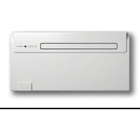
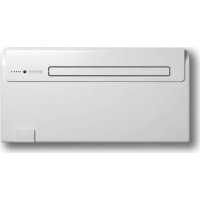
1. Airoutletdeector(Flap)
5. Condensation and emergency drains access door
To obtain the best results and optimum performance, follow the instructions for correct installation provided in this manual. A failure to implement the indicated standards, which may cause a malfunction of the appliances, relieves OLIMPIA SPLENDID from any form of warranty and from any liability for possible damages caused to people, animals or things. The electrical system must be compliant with legal standards, must respect the data in the technical data sheet and be must be equipped with an efcient ground system.UNICO PRO INVERTER R32 ENGLISH EN - 15 2.2- Sizeandspecicationsoftheroominwhichtoinstalltheairconditioner
- Before installing the air conditioner, it is essential to make an accurate calculation of the heat load in summer (and cold load in winter for models with heating pump) at the site of installation.
- The more accurate this calculation is made the better the air conditioner will be able to do its job.
- When executing the calculations, refer directly to the prevailing standards.
- For particularly important applications, we recommend contacting expert heating engineers.
- The user should try to limit high heat loads as much as possible as follows: glass doors and windows exposedtomanyhoursofsunlightshouldbettedontheinsidewithcurtainsor,evenbetter,onthe outsidewithcoveringssuchasVenetianblinds,verandahs,refractivelm,etc.).Theair-conditioned room must remain closed as long as possible.
- Halogen spotlights or other electrical equipment with high power consumption should not be used in the room (toasters, steam irons, hot plates for cooking, etc.).
2.3 - CHOOSING THE POSITION OF THE UNIT
To obtain the best operating performance and prevent faults or hazardous conditions, the position of indoor unit installation must meet the following requirements: a. Donotexposetheappliancetoheatorsteamsources(g.3). b. Make sure that the space to the right and left is at least 60 mm and space above the unit is at least 80 mm.(g.2). c. Theheightoftheunit’sloweredgefromtheoorshouldbeatleast100mmifxedtothewallinthe lowestposition.Ifxedtothewallinthehighestposition,itshouldbeatleast80mmfromtheceiling (g.2). d. Thewallwheretheindoorunitistobexed,mustbestable,strongandsuitabletosupporttheweight. e. It must be possible to leave room around the unit for any maintenance operations that may be necessary. f. Nothing should be in the way of the air that needs to circulate both on the top air-intake (curtains, plants, furniture) and at the front where the air exits. This could cause air swirls that would inhibit the working efciencyoftheunit(g.3). g. Donotspraywaterorotherliquidsofanykinddirectlyontheunit(g.3). h. Theappliancemustnotbepositionedsothattheairowisdirecteddirectlytowardsnearbypeople(g. 3).
i. Neverforcetheopeningoftheairowap(g.3).
l. Donotplacebottles,cans,clothes,owersoranyotherobjectontheairsuctiongrille(g.3). m. Do not install the air conditioner directly on another household appliance (TV, radio, fridge, etc.), or on aheatsource(g.3). The air conditioner must be installed on a wall that communicates with the outside
After determining the best place for installation as described above, check for the absence of other structures or systems (beams, piers, pipes, wires, etc.) at the points where the holes are to be drilled, which would prevent drilling the holes required to install the unit. Check again to make sure there are no obstacles to air circulation through the holes to be drilled due to plants and their leaves, slats or panelling, blinds, grat- ings or grids too dense, etc.).ENGLISH EN - 16
The maximum allowed length of the pipes is 1 m, the pipes must be internally smooth, with a di- ameter equal to 202 mm or 162 mm and bends cannot be performed. It is necessary to use the grilles provided, or grilles which keep the same features.
2.4.1 - Drilling the wall
Install the unit by drilling two holes (diameter of either 162 mm or 202 mm) in the wall as indicated in the drilling template. The 202-mm holes will ensure best performance and utmost noiselessness.
- It is possible to install the unit UNICO PRO INVERTER instead of a unit UNICO SKY or UNICO STAR or UNICO SMART or UNICO INVERTER without modifying the already existing holes, exception made for the small condensation drain hole. In this case, in order not to penalize performances, remove the insulating material possibly present in the air expulsion hole. The anchoring brackets need new drilling too.
- Drill the wall using the proper tools to facilitate your job and prevent excess damage or disturbance to your client. The best tools for drilling large holes in walls are special drills called core borers with very high twisting torque and adjustable rotating speed depending on the diameter of the hole to be drilled.
- Topreventthecreationoflargeamountsofdustandrubbleduetodrilling,thecoreborercanbetted with a vacuum system applied by means of suction cups to the drilling zone.
- To drill the holes, proceed as follows: - Place the supplied drill jig (M) against the wall observing the minimum distances from the ceiling, theoorandfromthesidewallsindicatedonthejigitselfwhichcanbekeptinthecorrectposition usingadhesivetape(Y)(g.4). - Use a small drill or punch to mark, with extreme care, the exact centre of each of the holes to be drilled(g.4). - Using a core boring head measuring at least 202 mm (or 162 mm) to drill the two holes for entry and exit of the air. Drill the foregoing holes tilted slightly downwards to prevent water from being fed back through the ducts (g. 5).
Most of the removed material is expelled outwards, therefore make sure that it does not hit any person or object when it falls out. In order to avoid as much as possible outer plaster breaking, it is necessary to proceed carefully with the last part of hole execution, decreasing pressure on core borers.UNICO PRO INVERTER R32 ENGLISH EN - 17
- Drilltheholes,previouslymarked,forthewallplugsrelatedtothexingbrackets(g.6). Carefully check the characteristics and consistency of the wall in order to possibly choose wall plugs specic for particular situations.
The manufacturer will not be held liable for any underestimates made in the structural consistency of the anchor prepared by the installer. Therefore, pay utmost attention to the foregoing operation that could cause serious injury/damage to people/property if carried out incorrectly.
- When installing models equipped with heating pump, if no condensate discharge was built into the wall (see paragraph 2.4.2), in order to drain the condensate it will be necessary to drill a hole through the wall in the position shown on the template.
- For cold-only machines, connect the condensate discharge pipe if you intend running the unit at low outdoor temperatures (lower than 23°C).
- Since condensate drains by gravity, there must be a minimum slope of at least 3% at every point of the dischargeline.Usearigidorexibletubehavinganinsidediameterofatleast16mm.
- If the line empties into a sewerage system, install a siphon before the point in which the pipe reaches themaindischarge,atleast300mmbelowtheinletfromtheunit(g.8).
- If the drainpipe drains into a vessel (tank or other container), this container should not be sealed and thedrainpipeshouldnotremainimmersedinthewater(seeg.9).
- Theholethroughwhichthecondensatepipepassesshouldalwaysslopetowardstheoutside(seeg. 10). The exact position in which to place the pipe inlet, as compared to the machine, is shown on the drilling template.
Make sure, in this case, that the water expelled outward does not damage or disturb persons or property. During the winter this type of drainage may cause sheets of ice to form.
When the condensate drainage is tted, pay much attention not to compress the rubber hose. In the event of operation during the winter with temperatures equal to or lower than 0° C, make sure that the condensate drain pipe is protected from freezing in order to ensure draining. In the event of prolonged operation during the winter with temperatures below 5°C, install the optional basin heater kit.ENGLISH EN - 18
2.4.3 - Assembly of the air ducts and external grids
- After drilling the holes (with the core drill), insert the plastic sheet (G) supplied with the air conditioner (g.11)insidethem. Since the sheet (G) was made for 202 mm holes, you will have to cut off 130 mm from the long side of thesheetforthe162mmholes(g.11). The sheets must be 65 mm shorter than the length of the wall.
- Roll the sheet (G) and insert it into the hole, paying attention to the splicing line, which must always face upwards. (g.12). Useanordinarycutterfortheforegoingoperation(g.12). To position the external grids, proceed as follows: a. Applytheseal(F)tothewallange(D),ensuringitlinesupwiththeouteredgeoftheangeasindicated inthegure13. b. Fixthetwoangesusing2pegshavingadiameterof6mmandcheckthatthetwoxingholesare horizontal(g.14-15-16). c. Fitthesmalleyeletofthespring,withthelongstem,onthecappin(onbothcomponents)(g.17). d. Insert the two caps (with spring), on the front part of the external grid, on its two housings, pulling until itclicks(g.18)andcouplethetwochainstothelargeeyeletofthespring. e. Using one hand, grip the two chains connected to the grid; f. Bendtheexternalgridsback,grippingthemwithyourfreehandwheretheybend,andinsertyourngers insidethesinglens(g.19).). g. Insert your arm into the pipe until the grid protrudes completely outwards. h. Reopenthegrid,beingcarefultokeepyourngersinsidethens.
i. Turnthegriduntilthensarefullyhorizontalandtilteddownwards.
Use exclusively the supplied grids (E), or grids with like characteristics.
2.4.4 - Preparing the holes on the machine
If Ø 200 mm holes are being used, work as follows: a. If 162 mm pipes are being used, the removal operation of part of the rear cover must not be performed. Thefanextensioncable(W)(g.21)mustberemoved. b. Useplierstobreakthepreblankingoftherearcover(g.22-A). c. Then, rotate the cover part to be removed back and forth with your hand until you break the remaining preblankedpart(g.22-B). d. Trimexcessiveinsulatingmaterialremainedinsidetheholeusinganutilityknife(g.22-B). The rear cover is also suitable for a rectangular suction channel. Ifyoupreferthistypeofinstallation,breaktherectangularpreblankingshowning.23anduseasuction grille of a size suitable for the suction channel.
2.4.5 - Positioning of the device on the anchor brackets
Workingonthetwopreviouslydrilledholes(seeg.6),xthesupportbrackets(L)tothewallusingthe suppliedwallplugsscrews(H)(g.24). After checking .......UNICO PRO INVERTER R32 ENGLISH EN - 19 .... thatthexingbracketsarewellanchoredtothewall, .... that the installation site has been prepared for electrical connection and condensation discharge (if necessary), it is possible to hook the air conditioner. Work as follows: a. Applyadhesivetape(A)tohavereferencestothehookingpointsoftheunit(g.25). The tape can be removed once the unit has been hooked to the wall. b. Raisetheairconditionerholdingitbythesidesofthelowerbaseandhookittothebrackets(L)(g.26). Slightly tilt the lower part of the appliance towards yourself to ease the operation.
- To make the electrical connection and fasten the drainpipe, place a wedge between the air con- ditioner and the wall (see g. 27).
- When you have nished, inspect carefully to make sure there are no ssures at the back of the air conditioner (the insulating gasket must t rmly against the wall) particularly in the zone where air enters and leaves the machine.
2.4.6 - Electric hook-up
Theapplianceisttedwithapowercordwithplug(Y-typeconnection). If the socket is in proximity to the appliance, simply plug it in.
Before connecting the conditioner, ensure that:
- The power supply voltage and frequency values comply with those indicated on the data plate of the appliance.
- The power supply line is tted with an efcient earth connection that is ap- propriately sized for the maximum absorption of the conditioner (minimum cross-section of the cable must be 1.5 mm
- The appliance is powered exclusively through a socket that is compatible with the plug supplied.
Any replacement of the power cable must be carried out solely by authorized technical support or by similarly qualied personnel. On the power supply line of the appliance there must be an adequate omnipolar disconnection device that complies with the national installation regulations. It is, however, necessary to check that the electrical power supply is equipped with efcient earthing and with adequate protections against overloading and/ or short circuits (a type 10 AT delayed fuse or other devices with equivalent functions are recommended).MODE DisplayLED5LED1
ENGLISH EN - 20 It is possible to proceed with the electrical connection using a cable embedded into the wall in a position as indicated in the installation template (recommended connection for installing the appliance is to the upper part of the wall).
- This operation must be performed only by the installer or any similarly qual- ied personnel and in compliance to the current national regulations.
Unscrew the cables locking screws of the terminal board (J2)(g.33)
i. Extract the old cable and insert the new one by following the same path.
o. Reassemble the front cover of the machine. This operation must be performed by specialized personnel possessing the requirements indicated by law.
Workasfollows(seeg.B): a. Insert the plug in the power socket to power the air conditioner, then make sure it is switched to stand-by mode. b. Press the key MODE for more than 10 seconds on the control panel, until an acoustic signal is emitted. c. The display shows parameter . d. Release the key MODE and press it again. e. Thedisplayshowsconguration (ceiling installation)
The input located on the terminal (Y2) of the main board (Y1) can be used to activate the functions ENERGY BOOST or SYSTEM ENABLEoftheairconditioner(g.46). CongurationanduseoftheinputENERGY BOOST or SYSTEM ENABLE: a. Insert the plug in the power socket to power the air conditioner, then make sure the latter is switched to stand-by mode. b. On the control panel, press the key MODE for more than 10 seconds until an acoustic signal is emitted. c. The display shows the parameter P0. d. Release the key MODE and press it again until you select the parameter PI. e. Release the key MODE and press it again for 2 seconds. f. Press keys + or -toselectthedesiredconguration. g. With value PI = 0, the input works from SYSTEM ENABLE. When the contact opens, the air conditioner is forced in stand-by mode. When the contact closes, the air conditioner restores its previous operation condition. h. With value PI≠0, the input works from ENERGY BOOST. When the contact opens, the display shows the code E, desired temperature is reduced by PI °C if the air conditioner is in cooling mode or increased by PI °C if the air conditioner is in heating mode. When the contact closes, the air conditioner restores its previous operation condition The input ENERGY BOOSThasnoeffectwhentheairconditionerisinfan,dehumidierorautomatic modes.
- This operation must be performed only by the installer or any similarly qual- ied personnel and in compliance to the current national regulations.
g. Reassemble the front cover of the machine. The input must be piloted by a potential-free dry contact. Do not use a cable longer than 10 meters.
2.7 - ACCESSORIES B1014, B1015
In case of installation of the accessories B1014 serial interface and/or B1012 wireless wall control, it is nec- essarytodisabledisplayvisualizationfromtheremotecontrol(keyB11)duringcongurationphase. When using the accessories B1014 and/or B1012, it is not possible to control the air conditioner neither from the remote control nor from the keys on the air conditioner console.MODE DisplayLED5LED1
The installation and electrical connection of the air conditioner should be carried out by specialized personnel who possess the requisites set forth by law. The installation instructions are contained in the appropriate paragraph of this manual. No structural object (furniture, curtains, plants, leaves, blinds, etc.) should ever obstruct the normal ow of air from either the internal or external gratings.
- Never lean or, worse yet, sit on the casing of the air conditioner as this could cause serious damage to the external parts. • Do not move the air outlet ap by hand. Always use the remote control to adjust bafe position. • If the unit leaks water, switch it off immediately and disconnect it from the power mains. Call the nearest service centre. • When the air conditioner is heating, it has to periodically eliminate any ice that could form on the external battery. While it is doing this, the machine keeps running but does not heat the room. This lasts for a brief period of time, from 3 to a maximum of 10 minutes. • Clean the air lter periodically, as described in the specic paragraph (4.1.2). The air conditioner must not be installed in rooms where explosive gasses de- velop or where there are conditions of heat and humidity beyond the maximum limits indicated in the installation manual.
3.2 - DESCRIPTION OF THE WARNING PANEL
In the upper right part of the appliance are located a few keys and LEDs whose functions are described below.UNICO PRO INVERTER R32
MODE DisplayLED5LED1 ENGLISH EN - 23 Keys Before performing the following operations, press one of the keys to enable the console. + Increase in the desired temperature (maximum value settable is 30°C/86F). - Decrease in the desired temperature. (minimum value settable in heating mode is 16°C/61F, in cooling mode is 18°C/64F). Activation/deactivation (Stand-by) of the air conditioner and ventilation speed selection. - Brief tap to select minimum, medium, maximum or automatic speed. - Prolonged press for activation/deactivation (Stand-by). MODE Operation mode selection and parameters setting - Brief tap (for more than 2 seconds) to select ventilation, cooling or heating operation modes - Prolonged press to enable parameters setting if in Stand-by mode + and - To be pressed simultaneously for at least 5 seconds to enable/disable the keypad lock function
and MODE To be pressed simultaneously and for an extended period of time (at least 5 seconds) to settozerothelterdirtyreport Others IR Infrared receiver B Buzzer
Heating mode 16÷30°C/61÷86F
The remote control supplied with the air-conditioner is the instrument that enables you to use the appliance in the most convenient way. It should be handled with care and in particular:
- Keep it dry (do not clean it with water or leave it outdoors in bad weather).
- Avoid dropping or bumping it.
- Keep it out of direct sunlight.
- The remote control operates by means of an infrared beam.
- During use, there must not be any obstacle between the remote control and the air-conditioner.
- If other appliances in the room have remote controls (TV, stereo, etc...), there may be interference with consequent loss of the sent signal.
- Electronic and uorescent lights may also interfere with transmissions between remote control and air-conditioner.
- Remove the batteries in case of prolonged disuse of the remote control.
- The remote control display goes off after a few seconds of non-use, to reactivate it press any key.
- Reset as described in paragraph 3.2UNICO PRO INVERTER R32 ENGLISH EN - 25
3.4.1 - Insertion of batteries
Toinsertthebatteriescorrectly(gure35-36): a. Remove the batteries compartment cover. b. Insert the batteries into the relevant compartment. Check the polarity indicated on the bottom of the compartment (g.36). c. Closethecompartmentcorrectly(g.37).
3.4.2 - Replacement of batteries
The batteries should be replaced when the display on the remote control does not appear sharply or when the remote control does not change the settings. Always use new batteries and replace both at the same time. The use of old or different batteries could generate malfunctioning of the remote control. The remote control uses two dry alkaline 1.5V batteries (AAA.LR03). When the batteries have been replaced, adjust the remote control clock.
When replacing batteries, replace both and dispose of the dead batteries in the appropriate collection centres and as required by law.
- If the remote control is not used for several weeks or longer, remove the batteries. Any leaks from the batteries could damage the remote control.
- The average life-span of the batteries, with normal use, is approx. six months. Replace the batteries when the indoor unit command receipt “beep” can no longer be heard, or if the transmission indicator on the remote control does not switch on.
Do not re-charge or disassemble the batteries. Do not throw the batteries into the re. They can burn and explode.
If the battery liquid falls onto the skin or clothes, wash well with clean water. Do not use the remote control with batteries that have leaked. The chemical products contained in the batteries can cause burns or other risks to health.
3.4.3 - Location of the remote controller
- Keep the remote control in a position from which the signal can reach the appliance receiver (maximum distanceisabout8meters-withchargedbatteries)(g.38). The presence of obstacles (furniture, curtains, walls, etc.) between the remote control and the appliance reduces the remote control range.D
The remote control is the interface between the air-conditioner and the customer, so it is very important to learn all its functions, the use of the various controls and the meaning of the symbols marked on it.
3.5.1 - Description of the remote control keys
B1 Activation/deactivation (Stand-by) of the unit B2 Minimum, medium, maximum or automatic ventilation speed selection B3 Activation/deactivation of the function SILENT B4 Activation/deactivation of the oscillation function of the air outletap B5 Operating mode selection - cooling > heating > ventilation > >dehumidication>automatic B6 Increase/Decrease desired temperature/clock/programming B7 Activation/deactivation of the report console display B8 Activation/deactivation of function ECO B9 Clock/programming setting B10 Activation/deactivation of the functions programming 1 / programming 2 B11 Activation/deactivation of the display on board of the machine switching on B12 Selection of the desired temperature unit °C / °F by pressing keys B6 simultaneously
3.6.1 - Main switch-on and running management
- The machine may be regulated using the remote control. In order to transmit commands to the indoor appliance, point the front of the remote control toward the appliance’s control panel. The device emits a beep when it receives a command.
- The maximum distance from which the appliance can be controlled is about 8 meters (with charged bat- teries).
- Press B8 on the remote control to activate the energy conservation function, automatically optimizing the machine features (on the display symbol D19 appears).
3.6.3 - Turning the unit ON/OFF
- Press key B1 on the remote control to activate or deactivate (stand-by) the air conditioner. The control system of the unit is equipped with memory, for this reason all the settings won’t be lost when shutting off the appliance itself.
In case of prolonged stop of the machine, it must be deactivated turning the main switch off or unplugging the machine from the mains.
3.6.4 - Operation in “Cooling” mode only
- Whenusedinthismode,theairconditionerdehumidiesandcoolstheroom.
- To activate this mode, press several times the key B5 on the remote control until when the symbol D2 appears on its display.
- In this run mode, the required temperature and fan speed can be set. After three minutes (as a maximum) from activation in this operating mode the compressor will start and the appliance starts emitting cold air.
3.6.5 - Operationin“Dehumidication”modeonly
- When used in this mode, the air conditioner eliminates the humidity in the room. This function can be extremely useful between seasons, particularly on rainy days when the temperature is not uncomfortable but the excess humidity feels unpleasant.
- In this mode, both room temperature and fan speed settings are ignored, which correspond to minimum.
- Any fan temperature and speed indication then disappears from the display (LED6) of the control panel (g.C).
- To activate this mode, press several times key B5 on the remote control until when symbol D3 and the automatic ventilation symbol D18(fan+rstnotch)appearonitsdisplay.
- In this operating mode it is normal for the air conditioner to function intermittently.ENGLISH EN - 28
3.6.6 - Operation in “Ventilation” mode only
- When used in this mode the air conditioner does not perform any action with regard to temperature and air humidity in the room.
- To activate this mode, press several times key B5 on the remote control until when the automatic venti- lation symbol D18(fan+rstnotch)appearsonitsdisplay.
3.6.7 - Operation in “Spa” mode only (Automatic)
- In this mode, the machine’s temperature is automatically regulated according to the room’s temperature. Thefanspeedisalsoautomaticallyregulatedaccordingtothesettemperature(exceptindehumidication mode).
- To activate this mode, press several times key B5 on the remote control until when symbol D5 appears on the display.
3.6.8 - Operationin“Heating”modeonly(onlymodelsttedwithheatingpump)
- Using this mode, the appliance heats the room. This function is only available for the versions with heat pump (HP).
- To activate this mode, press several times key B5 on the remote control until when symbol D1 appears on its display.
- In this run mode, the required temperature and fan speed can be set. After three minutes (maximum time) the compressor should start and the air conditioner starts heating the room. The air conditioner has to defrost its battery periodically. During this operation the air conditioner does not heat the room, though its internal parts remain on except for the room air fan. when the outdoor temperature is very low, there may be a slight delay for passage from the minimum to the medium or maximum speed from when the command is sent to the machine with the remote control. Like delays might occur on activating the swinging function of the mobile bafe. After having turned off the unit, the internal fan runs seconds more. Then it stops and both air aps close.UNICO PRO INVERTER R32 ENGLISH EN - 29
3.6.9 - Checkingairowdirection
- Press key B4 on the remote control to activate/deactivate the continuous oscillation of the moving air outletdeector(g.A-ref.1).
- When continuous oscillation is active, an additional press of the key B5allowstolockthedeectorsoas toobtainthedesiredverticaldirectionfortheairow. The moving deector position must never be forced manually.
3.6.10 - Checking fan speed
- The fan speed check occurs through key B2 (on the remote control).
- Pressing several times this key will cause speed to change according to the following sequence: Low > Medium > High > Automatic.
- The higher the speed setting, the greater the output of the air conditioner but also the louder its operation.
- By setting the Automatic mode, the onboard microprocessor adjusts the automatic speed. The higher the difference between the room temperature detected and the temperature set, the higher the speed.
- As the room temperature nears the setting, fan speed is reduced automatically.
- To activate this mode, press key B3 on the remote control (symbol D14 appears on the display).
- The activation of the function SILENT allows to obtain multiple results: - gradual increase in the set temperature during cooling mode - gradual decrease in the set temperature for heating (HP versions only) - reduction of the sound level of the appliance - reduction of ventilation speed
- To activate the function SILENT, it is necessary to select the operating mode and the desired temperature rst,thenpresskeyB3 to activate it.
- Noise reduction involves the machine noise and cooling/thermal power optimization. If, in certain moments, cooling/thermalpowerisinsufcient,disablethefunctionSILENT.
3.6.12 - Timer setting
- The appliance logic allows the User to make use of two different timer programs (see paragraph 3.6.14), thanks to which the appliance can be deactivated and activated (or vice versa) whenever desired (for example,itcanbeactivatedshortlybeforereturninghomesoastondanalreadypleasanttemperature in the room).
- Firstly, if it is desired to make use of these functions, set the correct time (see paragraph 3.6.13) and then set the timer as you prefer.F
3.6.13 - Timer and clock setting
To set time, work with the remote control as follows: a. Press key B9 (SET TIMER) until when the hour indication h (D11) appears on the display b. Set the hour with keys B6 (+ and -). c. Press the key B9 until when the minutes indication m (D11) appears on the display. d. Set the minutes with keys B6 (+ and -). e. Press key B9 to save the time and proceed with the timer programming.
3.6.14 - Timer setting
(PROGR. 1 and PROGR. 2) It is possible to set one or both the timer programs. To set the appliance activation and deactivation times in the two programs, use the remote control and work as follows: a. Press once or more key B9 (SET TIMER) until when symbol 1 (D6) (Activation time of the 1° program) and symbol ON (D10) appear on the display. b. Use keys B6 (+ and -) to increase or decrease the hour in which you wish the air conditioner activates. The hour variation settable with keys B6 (+ and -) is of 30 minutes. c. Press key B9 (SET TIMER) a second time; symbol 1 (D6) (Deactivation time of the 1° program) and symbol OFF (D7) appear on the display. d. Use keys B6 (+ and -) to increase or decrease the hour in which you wish the air conditioner switches off. The hour variation settable with keys B6 (+ and -) is of 30 minutes
e. Press key B9 (SET TIMER) again; symbol 2 (D9) (Activation time of the 2° program) and symbol ON (D10) appear on the display. f. Use keys B6 (+ and -) to increase or decrease the hour in which you wish the air conditioner activates. The hour variation settable with keys B6 (+ and -) is of 30 minutes
g. Press key B9 (SET TIMER) again; symbol 2 (D6) (Deactivation time of the 2° program) and symbol OFF (D7) appear on the display. h. Use keys B6 (+ and -) to increase or decrease the hour in which you wish the air conditioner switches off. The hour variation settable with keys B6 (+ and -) is of 30 minutes
3.6.15 - Timer activation and deactivation
Once set, the timer programs can either be activated or deactivated depending on occasional needs.Activation may relate to one of the two programs or both. In particular, each time you press key B9 (SET TIMER) (Programs activation), situation changes as follows:
- Use of Program no. 1 only.• Use of Program no. 2 only.• Use of Programs 1 and 2.• Disuse of both programs.
3.6.16 - Reset of all the remote control functions
Replacing the batteries or removing them even for a few instants will cause all the settings of the remote control to be reset.In so doing, all the time settings of the timer saved in the remote control are cancelled and the remote control restores all the factory settings.
3.6.17 - Managing the unit if the remote control is not available
In case of loss or malfunction of the remote control and/or exhaustion of the batteries, the appliance can be controlled from the keys on board of the machine.
3.7 - RECOMMENDATIONS FOR ENERGY SAVINGS
Belowndsimplerecommendationsforreducingconsumption:• Alwaysandconstantlykeeptheltersclean(seemaintenanceandcleaningchapter).• Keep the doors and windows of the rooms to be climate controlled closed.
- Avoid the sun’s rays penetrating freely into the room (we recommend using curtains or lowering blinds or closing the shutters).
- Donotobstructtheunitairow(inletandoutlet),i.e.inadditiontobadperformanceofthesystem,italso affects correct operation and the possibility of irreparable faults to the units.
4 - MAINTENANCE AND CLEANING
Before proceeding with any maintenance and cleaning, always make sure the system has been switched off, using the remote control, and the power supply plug has been disconnected from the system socket (or the upstream master isolating switch is positioned at “0” OFF).
Do not touch the metal parts of the unit when removing the air lters. They are very sharp. Cuts or injury risk.ENGLISH EN - 32
4.1.1 - Appliance and remote control cleaning
Useadryclothtocleantheapplianceandtheremotecontrol(g.44). It is possible to use a cloth moistened with cold water to clean the appliance if it is very dirty. Suckbetweentheairinletandoutletgrilles(g.44).
Do not use a chemically treated or antistatic cloth to clean the appliance. Do not use gasoline, solvent, polish or similar solvents. These products could cause the breakage or deformation of the plastic surface.
4.1.2-Cleaningtheairlter
If you plan to idle the unit for a long time, perform the following: a. Stop the air conditioner and disconnect the power supply. b. Remove the batteries from the remote control.
Do not perform them alone.
4.2.1 - Routine maintenance
The air conditioner that you have purchased has been designed to reduce routine maintenance operations to a minimum. These operations involve solely the cleaning operations outlined below:
- Cleaningorwashingoftheambientairlterevery2weeksoreverytimetherelativeredLEDlightsup (this can be done by the user, see user manual).
- Cleaning of the condensing battery and cleaning of the condensate management system.UNICO PRO INVERTER R32 ENGLISH EN - 33 These operations must be carried out by skilled technicians on a regular basis that will depend on the place of installation and intensity of use. Depending on the quantity of dirt, the unit can be cleaned dry (by using a battery compressor and bowl andcleaningthenswithasoftbrushtakingcarenottodeformthem)ormorethoroughlyusingdedicated detergents. Before you leave the site of installation you should gather up all packing material and use a damp cloth to removeanytracesofdustthatmayhavedepositedonthemachineduringassembly(g.24). Theseoperations,thoughcertainlynotessential,haveabenecialeffectastheyenhancetheprofessional image of the installer in the eyes of the client. To prevent unnecessary calls by the user, before you leave the site of installation
- it is also a good idea to:
- Explain the contents of the Instruction Manual to the user.
- Showtheuserhowtocleanthelter.
4.2.2 - Condensation water drainage in case of emergency
Should anomalies of the condensation water disposal system occur, the air conditioner stops and reports the alarm code 20 on the front panel display of the machine. To enable the air conditioner to work temporarily until the service personnel arrive, you can drain the water outbyfollowingthesesimpleinstructions(g.45): Before proceeding with any maintenance and cleaning, always make sure the system has been switched off, using the remote control, and the power supply plug has been disconnected from the system socket (or the upstream master isolating switch is positioned at “0” OFF). a. Open the door (6) underneath the unit. b. Remove the cap (6a) after having placed a good-sized container underneath it (at least 5-liter capacity) to collect the water. c. After having cleared the fault, the service personnel will close the evacuation pipe.
It is important for the User to distinguish between functional problems and anomalies in relation to the be- haviour of the appliance as foreseen for its normal operation. Furthermore, the most common problems may easily be solved through simple operations on behalf of the User (See paragraph: Anomalies and solutions). For all the other reports (see paragraph: 4.3.3 - Console alarms), it is necessary to always contact the technical assistance service”
Any attempt to repair the appliance by unauthorised personnel will immediately invalidate any form of guarantee.ENGLISH EN - 34
4.3.2 - Functional aspects not to be mistaken for anomalies
The following events may occur during normal operation: a. The compressor does not start up again immediately after a stop (it takes about three minutes to start again). - In the operating logic of the appliance a delay between a compressor stop and its successive restart has been included, so that the compressor itself is protected against activations that are too frequent. b. Duringtheheatingoperationoftheheatpumpappliances,theowofhotairmayoccursome minutes after activation of the compressor. - Shouldthefanstartatthesametimeasthecompressor,fortherstfewminutesitwouldemitcold air into the room (and this could bother the occupants) since the unit has not yet reached steady running conditions.
4.3.4 - Anomalies and remedies
Malfunctioning Cause What must be done? The unit will not start. Current failure Wait for the current to be restored. The unit is disconnected from the current. Check that the plug is inserted in the wall socket. The fuse is interrupted or the ther- mal-magnetic circuit breaker has tripped. Replace the fuse or restore the ther- mal-magnetic circuit breaker. The remote control batteries may be discharged. Replace the batteries. The time set with the timer may not be correct. Wait or annul the timer setting. The appliance doesn’t cool/heat sufcientlyanymore. Incorrect temperature setting. Set the temperature correctly. Consul the "Using the remote control" chapter for the procedure. Theairlterisdirty. Cleantheairlter. The doors or windows are open. Close the doors or windows. The air inlet or outlet vents of the indoor or outdoor units are blocked. First, remove the obstructions and then re-start the unit. The compressor 3 minute protection has activated. Wait. The appliance works but the report console is always switched off. The display has been set to OFF. Reactivate the display from the re- mote control. The appliance works but the report console keys don’t work. The keypad lock is active. Disable the keypad lock from the report console. If the problem has not been solved, please contact the nearest technical assistance service. Please give detailed information about the malfunction and on the equipment version.ENGLISH EN - 36
For the technical data listed below, consult the characteristic data plate afxed to the product.
- Power supply voltage
- Maximum power absorbed
- Maximum current absorbed
- Protection rating of the casings
- Max. operating pressure