Mc Kinley - Talkie Walkie PRESIDENT - Free user manual and instructions
Find the device manual for free Mc Kinley PRESIDENT in PDF.

User questions about Mc Kinley PRESIDENT
0 question about this device. Answer the ones you know or ask your own.
Ask a new question about this device
Download the instructions for your Talkie Walkie in PDF format for free! Find your manual Mc Kinley - PRESIDENT and take your electronic device back in hand. On this page are published all the documents necessary for the use of your device. Mc Kinley by PRESIDENT.
USER MANUAL Mc Kinley PRESIDENT
A Alpha H Hotel O Oscar V Victor B Bravo I India P Papa W Whiskey C Charlie J Juliett Q Quebec X X-ray D Delta K Kilo R Romeo Y Yankee E Echo L Lima S Sierra Z Zulu F Foxtrott M Mike T Tango G Golf N November U Uniform Español36
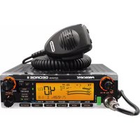
English40 Welcome to the world of the new generation of CB radios. The new PRESIDENT range gives you access to top performance CB equipment. With the use of up-to-date technology, which guarantees unprece- dented quality, your PRESIDENT MC KINLEY is a new step in personal communication and is the surest choice for the most demanding of professional CB radio users. To ensure that you make the most of all its capacities, we advise you to read carefully this manual before installing and using your PRESIDENT MC KINLEY. A) INSTALLATION
1) WHERE AND HOW TO MOUNT YOUR MOBILE CB RADIO
a) You should choose the most appropriate setting from a simple and practical point of view. b) Your CB radio should not interfere with the driver or the passengers. c) Remember to provide for the passing and protection of different wires (e.g. power, antenna, accessory cabling) so that they do not interfere in any way with the driving of the vehicle. d) To install your equipment, use the cradle (1) and the self-tapping screws (2) provided (drilling diameter 3.2 mm). Take care not to damage the vehicle’s electrical system while drilling the dash board. e) Do not forget to insert the rubber joints (3) between the CB and its support as these have a shock-absorbing effect which permits gentle orientation and tightening of the set. f) Choose where to place the microphone support and remember that the microphone cord must stretch to the driver without inter- fering with the controls of the vehicle. - WARNING: If you imbed your radio, please ensure that no cable is in direct contact with the chassis. - N.B. : As the transceiver has a frontal microphone socket, it can be set into the dash board. In addition to the loudspeaker on the front, it is possible to add an external speaker for better listening of communications (connector EXT.SP. situated on the back panel: C). Ask your dealer for advice on mounting your CB radio.
2) ANTENNA INSTALLATION
a) Choosing your antenna - For CB radios, the longer the antenna, the better its results. Your dealer will be able to help you with your choice of antenna. b) Mobile antenna - Must be fixed to the vehicle where there is a maximum of metallic surface (ground plane), away from windscreen mountings. MOUNTING DIAGRAM English41 - If you already have a radio-telephone antenna installed, the CB antenna should be higher than this. - There are two types of antenna: pre-regulated which should be used on a good ground plane (e.g. car roof or lid of the boot), and adjustable which offer a much larger range and can be used on a smaller ground plane (see § ADJUSTMENT OF SWR page 41). - For an antenna which must be fixed by drilling, you will need a good contact be- tween the antenna and the ground plane. To obtain this, you should lightly scratch the surface where the screw and tightening star are to be placed. - Be careful not to pinch or flatten the coaxial cable (as this runs the risk of break down and/or short-circuiting). - Connect the antenna (B). c) Fixed antenna - A fixed antenna should be installed in a clear space as possible. If it is fixed to a mast, it will perhaps be necessary to stay it, according to the laws in force (you should seek professional advice). All PRES- IDENT antennas and accessories are designed to give maximum efficiency to each CB radio within the range.
Your PRESIDENT MC KINLEY is protected against an inversion of polarities. However, before switching it on, you are advised to check all the connections. Your equipment must be supplied with a continued current of 12 or 24 volts (A). Today, most cars and lorries are negative earth. You can check this by making sure that the negative terminal of the battery is connected either to the engine block or to the chassis. If this is not the case, you should consult your dealer. a) Check that the battery is of 12 or 24 volts. b) Locate the positive and negative terminals of the battery (+ is red and - is black). Should it be necessary to lengthen the power cable, you should use the same or a superior type of cable. c) It is necessary to connect your CB to a permanent (+) and (-). We advise you to connect the power cable directly to the battery (as the connection of the CB cable to the wiring of the car-radio or other parts of the electrical circuit may, in some cases, increase the likelihood of interference). d) Connect the red wire (+) to the positive terminal of the battery and the black (-) wire to the negative terminal of the battery. e) Connect the power cable to your CB radio.
place the original fuse by one of a different value.
4) BASIC OPERATIONS TO BE CARRIED OUT BEFORE USING
YOUR SET FOR THE FIRST TIME (without transmitting and without using the “push-to-talk” switch on the microphone) a) Connect the microphone. b) Check the antenna connections. c) Turn the set on by turning the VOL knob (1) clockwise. d) Turn the squelch SQ knob (2) to minimum (M position). e) Adjust the volume to a comfortable level. f) Go to channel 20 by using the rotary CH knob (5) or UP/DN buttons (13) on the microphone.
5) ADJUSTMENT OF SWR (Standing wave ratio)
WARNING: This must be carried out when you use your CB radio
for the first time (and whenever you re-position your antenna). The adjustment must be carried out in an obstacle-free area.
- Adjustment with internal SWR-meter See function SWR CALIBRATION page 48.
- Adjustment with external SWR-meter (e.g. TOS-1 PRESIDENT)
OUTPUT RADIUS PATTERN
English42 a) To connect the SWR meter : - Connect the SWR meter between the CB radio and the antenna as close as possible to the CB (use a maximum of 40 cm cable, type President CA 2C). b) To adjust the SWR meter: - Set the CB on channel 20 in AM. - Put the switch on the SWR-meter to position FWD (calibration). - Press the “push-to-talk” switch on the microphone to transmit. - Bring the index needle to by using the calibration key. - Change the switch to position REF (reading of the SWR level). The reading on the Meter should be as near as possible to 1. If this is not the case, readjust your antenna to obtain a reading as close as possible to 1. (A SWR reading between 1 and 1.8 is acceptable). - It will be necessary to recalibrate the SWR meter after each ad- justment of the antenna.
WARNING: In order to avoid any losses and attenuations in cables
used for connection between the radio and its accessories, PRES- IDENT recommends to use a cable with a length inferior to 3 m. Your CB is now ready for use.
To turn on your set: turn the VOL knob (1) clockwise. If the KEY BEEP function is active (see KEY BEEP menu page 47), a beep sounds. Your radio is on. The display briefly shows the type of microphone (see MICROPHONE TYPE menu on page 48) and the frequency band used (see page 46). To turn off your set: turn the VOL knob (1) counter clockwise until it clicks. Your radio is off. To adjust the volume, turn the VOL knob (1) clockwise. To decrease the volume, turn the knob counter clockwise.
2) ASC (Automatic Squelch Control) / SQUELCH
Suppresses undesirable background noises when there is no com- munication. Squelch does not affect neither sound nor transmission power, but allows a considerable improvement in listening comfort. a) ASC: AUTOMATIC SQUELCH CONTROL Worldwide patent, a PRESIDENT exclusivity. Turn the SQ knob (2) anti-clockwise into ASC position. appears on the display. No repetitive manual adjustment and a permanent improvement between the sensitivity and the listening comfort when ASC is active. This function can be disconnected by turning the switch clockwise. In this case the squelch adjustment becomes manual again. disappears from the display. b) MANUAL SQUELCH Turn the SQ knob clockwise to the exact point where all background noises disappear. This adjustment should be done with precision, because if set to maximum (fully clockwise), only the strongest signals will be received.
It shows all functions: The main bargraph shows the reception level and the output power level. Smaller bargraph show Mic Gain, RF Gain and RF Power levels.
The function CLAR. allows a frequency deviation during LSB/USB reception in order to improve the clearness of your correspondent’s voice. English43
- Turn the rotary CH knob (5) to move up or down a channel. A beep sound is emitted each time the channel is changed if the KEY BEEP function is activated (see KEY BEEP function on page 47). See § UP/DN BUTTONS ON MICROPHONE page 46. The display shows the corresponding frequency. For example “27.205” for channel 20. See SPAN menu page 48. - A long press (3 seconds) on this button (5) allows entering the MENU. - A short press on this button (5) validates the settings in the MENU. RF POWER (combination 12 / 9 + 5) In TX mode, increase/decrease the output power. - Press and hold the PTT switch (12). - Press the • (9) and CH (5) buttons. «RF POWER» is displayed. - Turn the rotary CH knob (5) to adjust the level using the bargraph. - Press the CH knob (5) for 1 second to confirm the setting.
6) MODE ~ PA ~ •VOX ~ • VOX SETTING
MODE (short press) This switch allows selecting the modulation mode AM, FM, LSB or USB; Your modulation mode has to correspond to the one of your correspondent. - Amplitude Modulation / AM: communication on a field with relief and obstacles at middle distance (the most used). - Frequency Modulation / FM: for nearby communications on a flat open field. In U configuration only: in FM mode, a long press on the F key (10) alternates between the ENG or CEPT frequency bands. “UK” is displayed when the ENG frequency band is selected (see table on page 70). - Upper and Lower Side Band / USB-LSB: used for long distance communications (according to the propagation conditions). PA (Public Address) (long press) Long press PA key (6) to alternate between CB and PA mode. An external loud speaker can be connected to the unit by the PA jack plug located on the back panel PA.SP. (D). For details on operating in PA mode, see the PA SETTING menu on page 50. VOX (9 + 6 short press) The VOX function allows transmitting by speaking into the original microphone (or in the optional vox microphone) without pressing the PTT switch (12). The use of an optional vox microphone con- nected to the rear panel of the transceiver (E) disables the original microphone. Press • key (9) and short press •VOX key (6) in order to activate the VOX function. “VOX” appears on the display. Repeat the key combination to disable the function. “VOX” disappears. VOX SET (9 + 6 long press) Press the •key (9) and press during 1 second the •VOX key (6) in order to activate the function VOX SETTING. “VOX” is displayed. Three adjustments are possible: Sensitivity SET-L, Anti-vox level SET-A and Vox delay time SET-T. The Display shows the type of adjustment followed by its level , for example SET-L1.
1. Turn the CH knob (5) to increase/decrease the level of the active
2. Press the • VOX key (6) briefly to go to the next setting.
3. Once the VOX is correctly set, a long press (1 second) on the
- VOX key (6) will save the settings and exit the VOICE SETTING function. - Sensitivity “SET-L”: allows the adjustment of the microphone (original one or optional vox) for an optimum transmission quality. Adjustable level from 1 (high level) to 9 (low level).Default value: 1. - Anti-Vox “SET-A”: allows disabling the transmission generated by the surrounding noise. The level is adjustable. OFF (according the English44 squelch level) and from 0 (without anti-vox) to 9 (low level). Default value: OFF. - Delay time SET-T: allows avoiding the sudden cut of the transmission by adding a delay at the end of speaking. The level is adjustable from 1 (short delay) to 9 (long delay). Default value: 5. The VOX SETTING automatically activates the VOX function. “VOX” appears in the display. Note: The unit will automatically exit VOX SETTING without saving the setting parameters if no key is pressed after 10 seconds or, if any key is pressed.
SCAN (short press) Press the SCAN key (7) to activate the SCAN function in ascending order. “SCAN” is displayed. The scanning stops as a channel is active. The scanning automatically starts 3 seconds after the end of the transmission and no key is activated. In SCANNING mode, turn the rotary CH knob (5) or use the UP/DN buttons (13) on the microphone to change scan direction. During the scan, long press the • key (9) for one second to alternate between channel scan and memory scan modes. In the MEMORY SCAN mode, only the emergency channels (see § EMERGENCY CHANNELS on page 44) and the memorized channels (see § MEMORY page 45) are scanned. Press the PTT switch (12) or the SCAN key (7) to exit the SCAN function. DW (long press) A long press (1s) on the DW key (7) activates the DW (Dual Watch) function. “DW” is displayed. This function lets you watch over emergency and the current channels. - The first long press activates the DW function between emergency channel 1 and the current channel. - A second long press activates the function between the emergency channel 2 and the current channel. See § EMERGENCY CHANNEL 1 and 2 page 49. The current channel number and the emergency channel are displayed alternately. The “EMG” icon also appears along with the emergency channel. The selected channel can be changed during dual watch. - A new long press of the DW key (7) deactivates the DW function. “DW” disappears from the display.
ANB/NL (short press) ANL/NB (Automatic Noise Limiter / Noise Blanker): These filters reduce background noise and some noise on reception. Press the ANL/NB key (8) to alternate between the following 4 states in a loop: 1. ANL/on - NB/off • 2. ANL/off - NB/on • 3. ANL/ on - NB/on • 4. ANL/off - NB/off. The filter icon appears in the display when the filter is active (on). HI-CUT (long press) Hi-Cut cuts out the high frequency interferences. Press the HI-CUT key (8) for one second to activate/deactivate the HI-CUT filter. «HI-CUT» appears in the display when the filter is active. EMERGENCY CHANNELS (9 + 8 short press) - Briefly press the • key (9) then the •EMG (8) key to combine these two keys. - A first combination activates emergency channel 1. - A second combination activates emergency channel 2. - When an emergency channel is active, «EMG» is displayed. - A third combination allows to return to the initial channel. «EMG» disappears from the display. See § EMERGENCY CHANNEL 1 and 2 pages 49.
See § MEMORY page 45 English45 ECHO (9 + 9 short press) Press the • key (9) , flashes, then briefly press the •ECHO key (9) to activate the ECHO function. “ECHO” appears in the display. A new combination of the • (9) and •ECHO (9) keys, deactivates the function. “ECHO” disappears.
See In U configuration only on page 43. See § TALKBACK page 46. See § FUNCTION TURNING ON THE UNIT page 46. MIC GAIN (combination 12 / 9 + 10) Adjust the microphone sensitivity level. - Press and hold the PTT switch (12) - Press the • key (9). - Press the • MIC/RF GAIN key (10). “MIC GAIN” is displayed. - Turn the rotary CH knob (5) to adjust the level using the bargraph. - Press the CH knob (5) for 1 second to confirm the setting. The normal position of this function is at maximum level. MIC GAIN bargrah will be displayed on transmission. RF GAIN (9 + 10) Setting the reception sensitivity. Maximum position in the case of long-distance call reception. You can decrease the RF GAIN, to avoid distortions, when the interlocutor is near. Reduce the gain on reception in the case of a close communication with a corre- spondent not equipped with a RF POWER. - Press the • key (9). - Press the • MIC/RF GAIN key (10). “RF GAIN” is displayed. - Turn the rotary CH knob (5) to adjust the level using the bargraph. - Press the CH knob (5) button for 1 second to confirm the setting. The bargraph of the RF GAIN will always be displayed in reception.
9) “•” Key ~ MEMORY ~ ECHO ~ M3
“•” Key (short press) Pressing the • key (9) activates the FUNCTION mode. flashes. Combine with another key beginning with • (•VOX, •EMG, •ECHO,
- RF POWER or •MIC/RF GAIN) to access the function. Note: The • key (9) is always combined with another key. Pressing the key alone has no effect except to flash for 10 seconds. MEMORY (long press) This CB radio allows you to memorize 3 channels with the following attributes: NB/ANL (on/off), HI-CUT (on/off), AM / FM / USB / LSB. To store into memory: - Select the channel and its attributes. - Press the MEM key (9) for one second. If the KEY BEEP function is active, a beep sounds. “MEM” flashes. - Press for one second one of the keys M1 (7), M2 (8) or M3 (9) to memorize. “MEM” appears in the display and the number of the selected memory (M1, M2 or M3) flashes. - If the KEY BEEP function is active, a long beep confirms the success of the operation. To call a memory: - Press the MEM key (9) for one second. If the KEY BEEP function is active, a beep sounds. “MEM” flashes. - Briefly press one of the M1 (7), M2 (8) or M3 (9) keys to display the selected memory. - “MEM” is displayed, the number of the selected memory (M1, M2 or M3) flashes. To erase a memory: - Turn off the device. - Hold one of the keys M1 (7), M2 (8) or M3 (9) and switch on the appliance. - The selected memory is erased. “MEM” and the number of the selected memory (M1, M2 or M3) disappear from the display. See also the RESET menu on page 50. English46
11) 6 PIN MICROPHONE PLUG
The plug is located on the front panel of the transceiver and makes the setting of the equipment into the dashboard easier. See cabling diagram page 73.
12) PTT ~ RF POWER ~ MIC GAIN ~ TALKBACK
PTT (Push To Talk) Transmission switch, press to transmit a message, is displayed and release to listen to an incoming communication. RF POWER See § RF POWER page 43 MIC GAIN See § MIC GAIN page 45 TALKBACK (combination 12 / 10) The TALKBACK function allows to ear your own modulation with the CB speaker. While pressing PTT switch (12), - Press F key (10) to activate/deactivate TALKBACK function. When the function is on, “TALKBACK” is displayed. TALKBACK LEVEL (12 / 5) When the TALKBACK function is on, press and hold PTT switch (12) and turn the rotary CH knob (5) to adjust the TALKBACK level. 9 steps from 01 to 09. TOT (Time Out Timer) If the transmission (using the PTT (12) key or VOX) is more than 5 minutes, CHANNEL and start blinking, the transmission ends. The time-out tone will sound until the PTT key is released.
13) UP/DN BUTTONS ON MICROPHONE
- These buttons (13) allow increase (UP) or decrease (DN) the chan- nel. A beep sound is emitted whenever the channel is changed if the KEY BEEP function is activated (see BEEP KEY function on page 47). The display shows the corresponding frequency. For example “27.205” for channel 40. See SPAN menu page 48. See § CHANNEL SELECTOR CH on page 43.
C) FUNCTION TURNING ON THE UNIT
To select the FREQUENCY BAND turn off the unit. Press and hold the F key (10) and then turn the unit on. (Configuration: EU; PL; d; EC; U; In) The frequency bands have to be chosen according to the country of use. Don’t use any other configuration. Some countries need a user’s licence. See table page 75.
1. Turn on the power while pressing the F key (10). The letter corre-
sponding to the current configuration is blinking.
2. In order to change the configuration, turn the rotary CH knob (5)
on the unit or use the UP/DN buttons (13) on the microphone.
3. When the configuration is selected, press the F key (10) during 1
second. The letter corresponding to the configuration is continu- ously displayed and a confirmation beep sounds.
4. At this point, confirm the selection by switching off the transceiver
and then switching it on again. See the frequency bands table at pages 70 to 72 / configu- ration table page 74. D) MENU The order of the 14 functions is the one described in this manual. However, the function displayed when entering the MENU will be the last function modified by the user. Whatever the function, the procedure is the same: Press the CH knob (5) for 3 seconds to enter MENU. appears.
selected menu flashes in the display.
5. If no key is pressed, the unit exits MENU after 10 seconds. dis-
appears from the display. Note: The UP/DN buttons (13) on the microphone have the same effect as the rotary CH knob (5). The PTT switch (12) exits MENU without validating. disappears from the display.
Press the CH knob (5) for 3 seconds to enter MENU. appears.
2. Press the CH knob (5) to confirm. The color flashes in the display.
3. Turn the rotary CH knob (5) or use the UP/DN buttons (13) on the
microphone to change the color. 4a. Short press the CH knob (5) again to validate the color and stay in the MENU. 4b. Long press (1s) the CH knob (5) again to validate the color and exit in the MENU. disappears from the display.
5. If no key is pressed, the unit exits MENU after 10 seconds. dis-
appears from the display. Color default is orange :
DIMMER function allows adjusting the brightness of the lighting. 10 steps from 0 to 9. Press the CH knob (5) for 3 seconds to enter MENU. appears.
2. Press the CH knob (5) to confirm. The dimmer value flashes in the
microphone to change the value of the dimmer. 4a. Short press the CH knob (5) again to validate the selected value and stay in the MENU. 4b. Long press (1s) the CH knob (5) again to validate the selected value and exit in the MENU. disappears from the display.
5. If no key is pressed, the unit exits MENU after 10 seconds. dis-
appears from the display. Dimmer default value is : 5.
CONTRAST function allows adjusting the contrast of the display. 10 steps from 0 to 9. Press the CH knob (5) for 3 seconds to enter MENU. appears.
2. Press the CH knob (5) to confirm. The contrast value flashes in the
microphone to change the value of the contrast. 4a. Short press the CH knob (5) again to validate the selected value and stay in the MENU. 4b. Long press (1s) the CH knob (5) again to validate the selected value and exit in the MENU. disappears from the display.
5. If no key is pressed, the unit exits MENU after 10 seconds. dis-
appears from the display. Contrast default value is : 5.
Beep on changing the channel, keys etc... Press the CH knob (5) for 3 seconds to enter MENU. appears.
microphone to activate
the function. “BP” appears on the LCD when the function is activated. English48 4a. Short press the CH knob (5) again to validate and stay in the MENU. 4b. Long press (1s) the CH knob (5) again to validate and exit in the MENU. disappears from the display.
5. If no key is pressed, the unit exits MENU after 10 seconds. dis-
appears from the display. Key beep default setting is : on.
The Roger Beep sounds when the PTT switch (12) of the microphone is released in order to let your correspondent speak. Historically as CB is a “simplex” communication mode, it is not possible to speak and listen at the same time (as it is the case with a telephone). Once the conversation was over, he said “Roger” in order to prevent his correspondent that it was his turn to talk. The word “Roger” has been replaced by a significant beep. There comes “Roger beep” from. Press the CH knob (5) for 3 seconds to enter MENU. appears.
microphone to activate
the function. “ ” appears on the LCD when the function is activated. 4a. Short press the CH knob (5) again to validate and stay in the MENU. 4b. Long press (1s) the CH knob (5) again to validate and exit in the MENU. disappears from the display.
5. If no key is pressed, the unit exits MENU after 10 seconds. dis-
appears from the display. Roger beep default setting is :
When the function is active, the frequency can be adjusted con- tinuously. Pressing the CH knob (5) button displays a bar under the first or second decimal of the frequency. The rotary CH knob (5) no longer acts on the channel but execute a 100 kHz (first decimal place) or 10 kHz (decimal second) jump frequency. Press the CH knob (5) for 3 seconds to enter MENU. appears.
microphone to activate
the function. 4a. Short press the CH knob (5) again to validate and stay in the MENU. 4b. Long press (1s) the CH knob (5) again to validate and exit in the MENU. disappears from the display.
5. If no key is pressed, the unit exits MENU after 10 seconds. dis-
appears from the display. Span default setting is
PRESIDENT MC KINLEY can be used with both a PRESIDENT electret and dynamic 6-pin microphone (see microphone wiring on page 73). When the unit is turned on, the microphone type is displayed briefly. Press the CH knob (5) for 3 seconds to enter MENU. appears.
2. Press the CH knob (5) to confirm. The type of the microphone
flashes in the display.
3. Turn the rotary CH knob (5) or use the UP/DN buttons (13) on the
microphone to select the type of the microphone (electret) or dynamic. 4a. Short press the CH knob (5) again to validate and stay in the MENU. 4b. Long press (1s) the CH knob (5) again to validate and exit in the MENU. disappears from the display.
5. If no key is pressed, the unit exits MENU after 10 seconds. dis-
appears from the display. Microphone type default is (electret).
Press the CH knob (5) for 3 seconds to enter MENU. appears.
English49 switches to TX mode without pressing the PTT switch (12) and calibration begins. Calibration time is 5 minutes maximum. A countdown is done in the display.
3. Adjust the antenna.
- The beep* is continuous when the SWR value is 1.0. The space between the beeps becomes larger and larger as the SWR value moves away from1.0. - The volume of the beep is adjustable with the VOL button (1). - The display shows the SWR value, for example 2.5.
4. Press the PTT switch (12) to exit the SWR CALIBRATION.
*Check that the beep volume is set to a suitable level. See ADJUSTMENT OF SWR page 41.
Press the CH knob (5) for 3 seconds to enter MENU. appears.
flashes in the display.
The second parameter, DELAY, flashes.
stops flashing. a) Start again at point 1 to set another function or b) Press the PTT switch (12) to exit MENU.
7. If no key is pressed, the unit exits MENU after 10 seconds. dis-
appears from the display. See § ECHO page 45.
This function allows to change the RX TONE. 11 steps from -5 to
Press the CH knob (5) for 3 seconds to enter MENU. appears.
2. Press the CH knob (5) to confirm. The tone value flashes in the
microphone to change the value of the tone. 4a. Short press the CH knob (5) again to validate the selected value and stay in the MENU. 4b. Long press (1s) the CH knob (5) again to validate the selected value and exit in the MENU. disappears from the display.
5. If no key is pressed, the unit exits MENU after 10 seconds. dis-
appears from the display. Tone default value is : 0.
11) EMERGENCY CHANNEL 1
Press the CH knob (5) for 3 seconds to enter MENU. appears.
modulation mode, flashes in the display.
3. Turn the rotary CH knob (5) or use the UP/DN buttons (13) on the
microphone to set the modulation mode for emergency channel 1: AM, FM, USB, LSB or FM UK (in U configuration only).
4. Press CH knob (5) again to confirm. The modulation mode stops
flashing, the second parameter, the channel, flashes in the display.
5. Use the rotary CH knob (5) or use the UP/DN buttons (13) on the
microphone to select the emergency channel 1.
6. Press CH knob (5) again to confirm the channel. a) Start again at
point 1 to set another function or b) Press the PTT switch (12) to exit MENU.
7. If no key is pressed, the unit exits the MENU after 10 seconds.
disappears from the display. Emergency channel 1 default is 9 in AM. See § EMERGENCY CHANNELS page 44.
12) EMERGENCY CHANNEL 2
Press the CH knob (5) for 3 seconds to enter MENU. appears. English50
1. Turn the rotary CH knob (5) or use the UP/DN buttons (13) on the
microphone to select the EMG 2 menu. Items 2 to 7 are identical to those in EMERGENCY 1 SET. Emergency channel 2 default is 19 AM. See § EMERGENCY CHANNELS page 44.
This function allows to select the operating mode of PA, Public Address. Press the CH knob (5) for 3 seconds to enter MENU. appears.
1. Turn the rotary CH knob (5) or use the UP/DN buttons (13) on the
microphone to select the PA SET menu.
microphone to select the operating mode of the PA : PA, In or OF. 4a. Short press the CH knob (5) again to validate the PA type and stay in the MENU. 4b. Long press (1s) the CH knob (5) again to validate the PA type and exit in the MENU. disappears from the display.
5. If no key is pressed, the unit exits MENU after 10 seconds, dis-
appears in the display. - PA: the modulation of the microphone and the received signal are transmitted to the Public Address loudspeaker connected to jack PA.SP. (D). “PA” flashes alternately with the modulation mode used: AM, FM, LSB, SSB or FM UK (only in U configuration). - In : the modulation of the microphone is transmitted to external loudspeaker connected to jack PA.SP. (D). The received signal is transmitted to the internal loudspeaker [or external optional loudspeaker connected to jack EXT.SP (C)].“PA” flashes alternately with the modulation mode used: AM, FM, LSB, SSB or FM UK (only in U configuration). - OF: The reception is no more functional. Only the modulation of the microphone is transmitted to the Public Address loudspeaker connected to jack PA.SP. (D). “PA” is displayed, channels are replaced by PA. In PA mode, press PTT switch to display “PA LEVEL”. Then turn the rotary CH knob (5) to adjust the audio level of the PA. PA setting default is: PA. See § PA (Public Address) page 43.
Resets all user-defined settings and returns to default values. Press the CH knob (5) for 3 seconds to enter MENU. appears.
2. Press the CH knob (5) to validate. “CONFIRM” is displayed, no flashes
5. If no key is pressed, the unit exits MENU after 10 seconds, dis-
- Channels : 40 - Modulation modes : AM / FM / USB / LSB - Frequency ranges : from 26.965 MHz to 27.405 MHz - Antenna impedance : 50 ohms - Power supply : 13.2 V / 26.4 V - Dimensions (W x D x H) : 170 (W) x 150 (D) x 52 (H) mm - Weight : 1 kg - Accessories supplied : microphone UP/DOWN with support, mounting cradle, screws and fused power cord.
- Check that the antenna is correctly connected and that the SWR is properly adjusted. - Check that the microphone is properly plugged in. - Check that the RF POWER bargraph is set on maximum. - Check that the MIC GAIN bargraph is set on maximum.
2) YOUR CB RADIO WILL NOT RECEIVE OR RECEPTION IS
POOR - Check that the RF GAIN bargraph is set on maximum. - Check that the squelch level is properly adjusted. - Check that the volume is set to a comfortable listening level. - Check that the antenna is correctly connected and that the SWR is properly adjusted.
3) YOUR CB WILL NOT LIGHT UP
- Check the power supply. - Check the connection wiring. - Check the fuse. G) HOW TO TRANSMIT OR RECEIVE A MESSAGE Now that you have read the manual, make sure that your CB Radio is ready for use (i.e. check that your antenna is connected). Press the “push-to-talk” switch and announce your message “At- tention stations, transmission testing” which will allow you to check the clearness and the power of your signal. Release the switch and wait for a reply. You should receive a reply like, “Strong and clear”. If you use a calling channel (19) and you have established commu- nication with someone, it is common practice to choose another available channel so as not to block the calling channel. English52 H) GLOSSARY Below you will find some of the most frequently used CB radio expressions. Remember this is meant for fun and that you are by no means obliged to use them. In an emergency, you should be as clear as possible.
INTERNATIONAL PHONETIC ALPHABET
A Alpha H Hotel O Oscar V Victor B Bravo I India P Papa W Whiskey C Charlie J Juliett Q Quebec X-ray D Delta K Kilo R Romeo Y Yankee E Echo L Lima S Sierra Z Zulu F Foxtrott M Mike T Tango G Golf N November U Uniform TECHNICAL VOCABULARY AM : Amplitude Modulation CB : Citizen’s Band CH : Channel CW : Continuous Wave DX : Long Distance Liaison DW : Dual Watch FM : Frequency Modulation GMT : Greenwich Meantime HF : High Frequency LF : Low Frequency LSB : Lower Side Band RX : Receiver SSB : Single Side Band SWR : Standing Wave Ratio SWL : Short Wave Listening SW : Short Wave TX : CB Transceiver UHF : Ultra High Frequency USB : Upper Side Band VHF : Very High Frequency CB LANGUAGE Advertising : Flashing lights of police car Back off : Slow down Basement : Channel 1 Base station : A CB set in fixed location Bear : Policeman Bear bite : Speeding fine Bear cage : Police station Big slab : Motorway Big 10-4 : Absolutely Bleeding : Signal from an adjacent channel interfering with the transmission Blocking the channel : Pressing the PTT switch without talking Blue boys : Police Break : Used to ask permission to join a conversation Breaker : A CBer wishing to join a channel Clean and green : Clear of police Cleaner channel : Channel with less interference Coming in loud and proud : Good reception Doughnut : Tyre Down and gone : Turning CB off Down one : Go to a lower channel Do you copy? : Understand? DX : Long distance Eighty eights : Love and kisses Eye ball : CBers meeting together Good buddy : Fellow CBer Hammer : Accelerator Handle : CBer’s nickname Harvey wall banger : Dangerous driver How am I hitting you? : How are you receiving me? Keying the mike : Pressing the PTT switch without talking Kojac with a kodak : Police radar Land line : Telephone Lunch box : CB set Man with a gun : Police radar Mayday : SOS Meat wagon : Ambulance Midnight shopper : Thief English53 Modulation : Conversation Negative copy : No reply Over your shoulder : Right behind you Part your hair : Behave yourself - police ahead Pull your hammer back : Slow down Rat race : Congested traffic Rubberbander : New CBer Sail boat fuel : Wind Smokey dozing : Parked police car Smokey with a camera : Police radar Spaghetti bowl : Interchange Stinger : Antenna Turkey : Dumb CBer Up one : Go up one channel Wall to wall : All over/everywhere What am I putting to you? : Please give me an S-meter reading English SIMPLIFIED EU
DECLARATION OF CONFORMITY
Technical Manager and Quality Manager This device is guaranteed 2 years parts and labour in its country of purchase against any manu- facturing defects validated by our technical department. *The After-sales Service of PRESIDENT reserves the right not to apply the warranty if a breakdown is caused by an antenna other than those distributed by PRESIDENT, and if said antenna is at the origin of the breakdown. An exten- sion of 3 years warranty is proposed systematically for the purchase and use of a PRESIDENT antenna, bringing the total duration of the warranty to 5 years. In order to be valid, the warranty certificate must be returned within a period of 30 days after the purchase date to the After-sales Service of the company Groupe President Electronics, or any foreign subsidiary. It is recommended to carefully read the following conditions and to respect them under penalty of losing their benefit.
- To be valid the warranty certificate must be returned to us at the latest 1 month after the purchase.
- Please duly complete the warranty certificate on the right hand side of the page, detach it (portion to be removed marked by dotted line) and send it back.
- Any repair under warranty will be free and the return delivery costs will be borne by our company.
- A purchase proof must be necessarily included with the device to be repaired.
- The dates listed on the warranty certificate and proof of purchase must match.
- Do not proceed with the installation of the device without reading the user manual.
- No spare part will be sent nor exchanged by our services under warranty. The warranty is only valid in the country of purchase. Exclusions (are not covered)
- Damages caused by accident, shock or inadequate packaging.
- Power transistors, microphones, lights, fuses and the non respect of the installation and use of specifications (including but not limited to antenna used with too high power, final output power transistors (SWR), inversion of polarities, bad connections, overvoltage,….)
- The warranty cannot be extended due to the non-availability of the device while it is being serviced at our technical services location, nor by a change of one or more components or spare parts.
- Transceivers which have been modified. The warranty application is excluded in case of modification or poor maintenance done by a third party not approved by our company. If you note malfunctions
- Check the power supply of your device and the quality of the fuse.
- Check that the antenna, the microphone…. are correctly connected.
- Check that the squelch level is properly adjusted; the programmed configuration is the correct one...
- In case the device is not under warranty, the repair and return of the device will be charged.
- All related documents must be preserved even after the end of the warranty period and if you resell your device, given to the new owner for the After-sales follow-up.
- In case of real malfunction, please contact your dealer first; they will decide action to be taken.
configuration in FM mode: In order to select the frequency band ENG , press during one second the F key (
) until “UK” appears in the display. In order to select the CEPT frequency band, press during one second the F key (
) until “UK” disappears from the display (see table at page 70)