
HB350 - Drill MAKITA - Free user manual and instructions
Find the device manual for free HB350 MAKITA in PDF.
| Product type | Magnetic drill |
| Brand | Makita |
| Model | HB350 |
| Cutting capacity | 35 mm |
| Chuck capacity | 13 mm |
| No load speed | 850 rpm |
| Power consumption | 1050 W |
| Clamping force | 8000 N (815 kg) |
| Dimensions (L x H x W) | 225 × 490 × 195 mm |
| Weight | 11 kg |
| Supply voltage | 110/230 V |
| Sound pressure level | 89.13 dB(A) |
| Sound power level | 100.12 dB(A) |
| Intended use | Drilling holes in ferrous metals |
| Power supply | Mains |
| Integrated cooling system | Yes |
| Carrying case | Included |
| Included accessories | Allen keys, safety strap, protection |
| Recommended maintenance | Lubrication of rack, Molycote grease on carriage, cleaning after use |
| Safety | Safety strap mandatory, eye and hearing protection |
| Warranty | Manufacturer's warranty included |
Frequently Asked Questions - HB350 MAKITA
User questions about HB350 MAKITA
0 question about this device. Answer the ones you know or ask your own.
Ask a new question about this device
Download the instructions for your Drill in PDF format for free! Find your manual HB350 - MAKITA and take your electronic device back in hand. On this page are published all the documents necessary for the use of your device. HB350 by MAKITA.
USER MANUAL HB350 MAKITA
To get the best possible performance from your new MagneticDrilling Machine , please read this carefully BEFORE using the drill.
For your personal safety, READ and UNDERSTAND before using.
SAVE THESE INSTRUCTIONS FOR FUTURE REFERENCE.
BEFORE YOU START
To help you get the best possible performance from your new Magnetic Drilling Machine, this guide contains simple, sensible pointers for the safe, effective, and long-term use of the equipment.
Please read it carefully before using the drill.
- Ensure that you have observed all the general and specific safety procedures.
Explanation of the pictograms on the specification plate of the Makita HB350

DANGER!
Indicates an imminent danger or risk to life and health of a general nature.

ELECTRICAL DANGER!
This means a direct pending danger or risk to life due to electricity.

CAUTION!
Indicates a possible danger or risk of slight injury or damage to property.

WEAR EYE & EAR PROTECTORS

USE SAFETY STRAP!
to attach the tool to the workpiece.

READ THE MANUAL
Read the manual before operating the machine.
WEEE compliance certificate:- on request
All magnetic drilling systems are fully compliant with RoHS regulations.
Due to the presence of hazardous components in the equipment, used electrical and electronic equipment may have a negative impact on the environment and human health.
Do not dispose of electrical and electronic appliances with household waste.
In accordance with the European Directive on waste Electrical and electronic equipment should be collected separately and delivered to a separate collection point for municipal waste, operating in accordance with the environmental protection regulations.
this is indicated by the symbol of the crossed out wheeled bin placed on the equipment.
CONTENTS
HB350 Specification
The Broach Cutting Concept
- Intended Use
General Safety Instructions
Material and Cutting speeds
Feeds and Speeds
Fitting Safety Guard & Strap and Oil Bottle
Fitting Cutters
Panel Operation
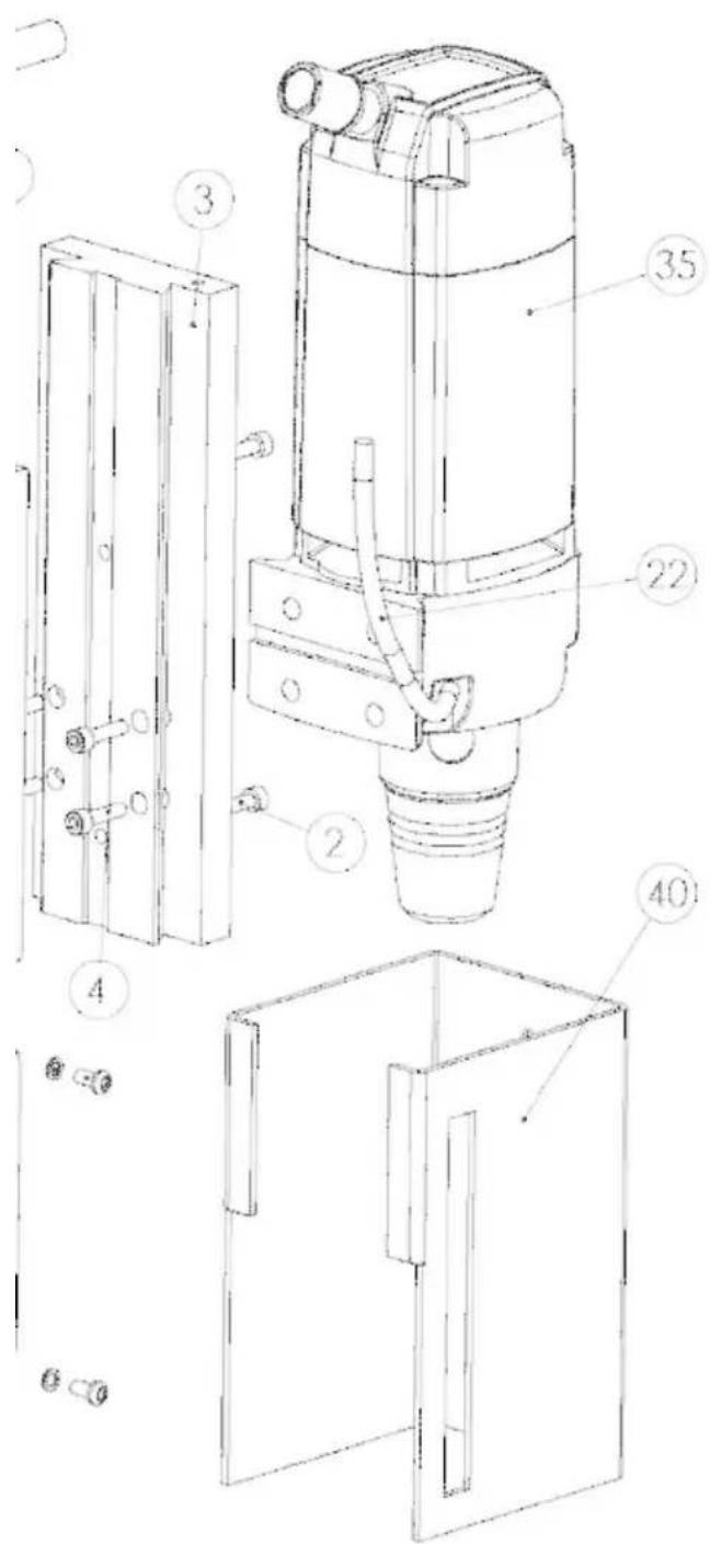
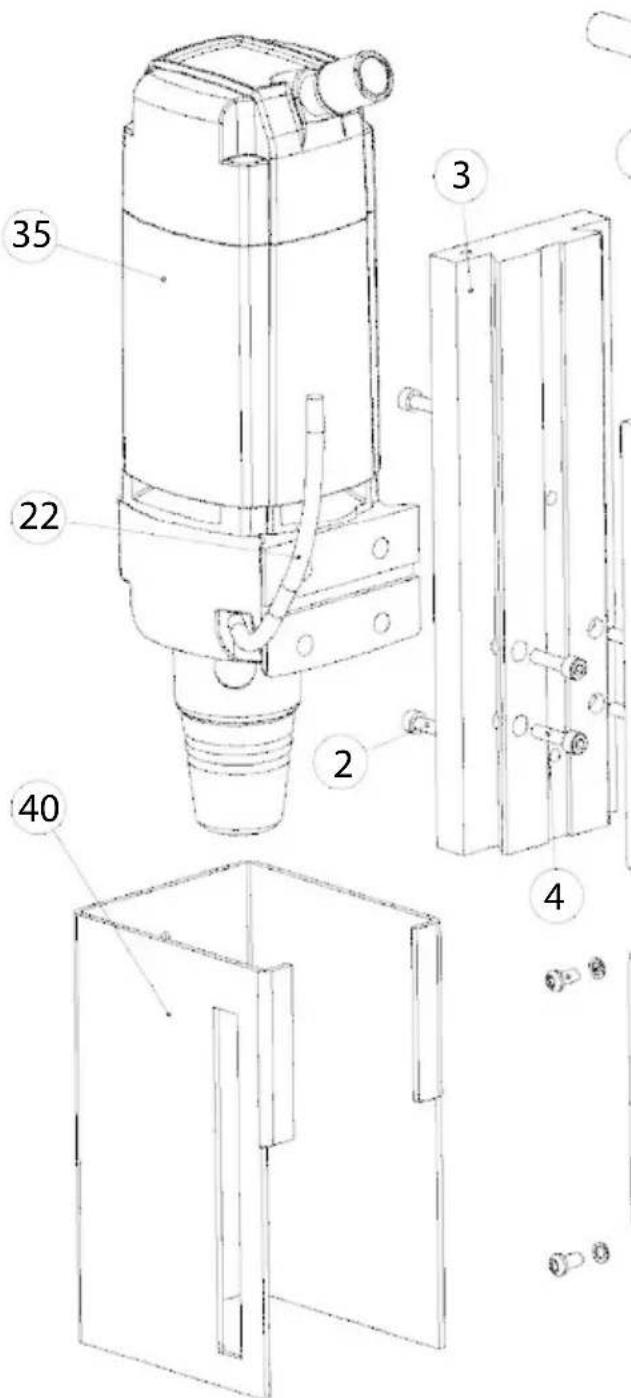
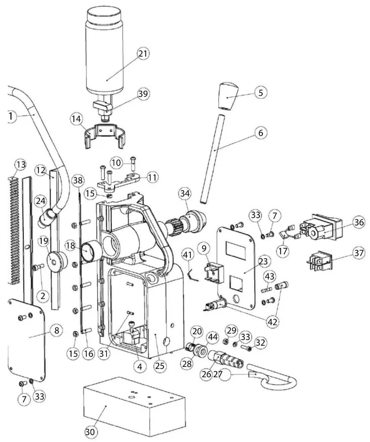
Motor diagram & parts list
- Stand diagram & parts list
EC Declaration

HB350 SPECIFICATION
Cutter capacity -35mm
Chuck Capacity -13mm
No load speed -850 rpm
Power consumption - 1050w
Clamping force -8000N (815kg)
L×H×W(mm) -225×490×195
Weight -11.
Voltage -110/230v
Sound pressure level - 89.13 dB(A)
Sound Power level - 100.12 dB(A)
INCLUDES: Integral co olant s y stem, Warra nty , Carrying case, Allen keys, Safety strap & Guard
- Due to our continuing programme of research and development, these specifications are subject to change without notice.

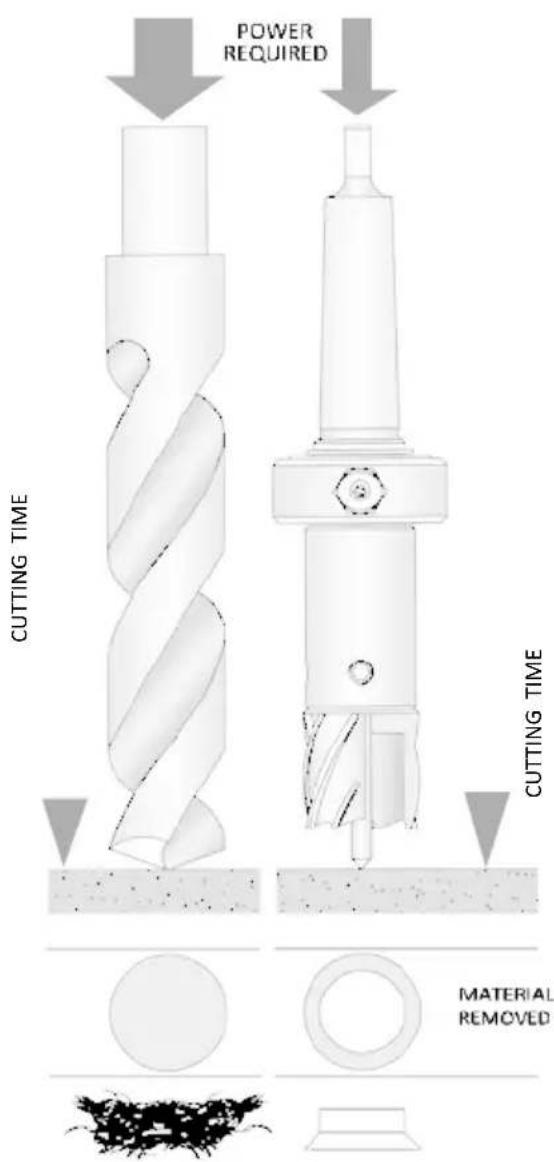
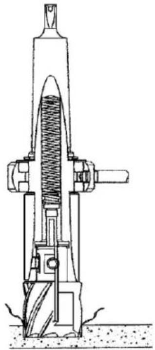
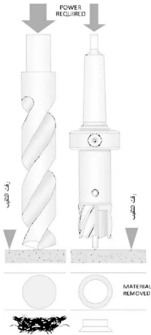
THE BROACH CUTTING CONCEPT
If you are unfamiliar with the use of annular (or broaching) cutters, take a few minutes to read this guide - you will benefit from the better performance and longer life of the tool if you understand the concept.
Annular cutters only cut marerial at the periphery of the hole, rather than converting the entire hole to shavings. As a result, the time and energy required to make the hole is lower than for a traditional twist drill.
The broaching capacity of a machine is therefore, greater than the twist drill capacity. The slug ejected after the cut also has a higher scrap value than shavings.
Optional Accessories
For details of options, either refer to the catalog or inquire at the store of purchase or a Makita sales office.
CAUTION: These accessories or as achments are recommended for use with your Makita tool specified in this manual. The use of any other accessories or attachments might present a risk of injury to persons. Only use accessory or attachment for its stated purpose.
If you need any assistance for more details regarding these accessories, ask your local Makita Service Center.
HSS Cutter
TCT Cutter
- Drill chuck
INTENDED USE
The intended use of this magnetic drill is to drill holes in ferrous metals. The magnet is used to hold the drill in place whilst the drill is functioning. It is designed for use in fabrication, construction, railways, petrochemical, and any other applications when drilling ferrous metal.
Any deviation from its intended use will not be covered by warranty.
GENRAL POWER TOOL SAFETY INSTRUCTIONS
General power tool safety warnings
WARNING Read all safety warnings, instructions, illustrations, and specifications provided with this power tool. Failure to follow all instructions listed below may result in electric shock, fire and/or serious injury.
Save all warnings and instructions for future reference.
The term "power tool" in the warnings refers to your mains-operated (cored) power tool or battery-operated (cordless) power tool.
1) Work area safety
2) Electrical safety
a) Keep work area clean and well lit. Cluttered or dark areas invite accidents.
b) Do not operate power tools in explosive atmospheres, such as in the presence of flammable liquids, gases, or dust. Power tools create sparks which may ignite the dust or fumes.
c) Keep children and bystanders away while operating a power tool. Distractions can cause you to lose control.
a) Power tool plugs must match the outlet. Never modify the plug in any way. Do not use any adapter plugs with earthed (grounded) power tools. Unmodified plugs and matching outlets will reduce risk of electric shock.
b) Avoid body contact with earthed or grounded surfaces, such as pipes, radiators, ranges, and refrigerators. There is an increased risk of electric shock if your body is earthed or grounded.
c) Do not expose power tools to rain or wet conditions. Water entering a power tool will increase the risk of electric shock.
d) Do not abuse the cord. Never use the cord for carrying, pulling, or unplugging the power tool. Keep cord away from heat, oil, sharp edges or moving parts. Damaged or entangled cords increase.
the risk of electric shock.
e) When operating a power tool outdoors, use an extension cord suitable for outdoor use. Use of a cord suitable for outdoor use reduces the risk of electric shock.
f) If operating a power tool in a damp location is unavoidable, use a residual current device (RCD) protected supply. Use of an RCD reduces the risk of electric shock.
NOTE The term "residual current device (RCD)" can be replaced by the term "ground fault circuit interrupter (GFCI)" or "earth leakage circuit breaker (ELCB)".
3) Personal safety
a) Stay alert, watch what you are doing and use common sense when operating a power tool. Do not use a power tool while you are tired or under the influence of drugs, alcohol, or medication. A moment of inattention while operating power tools may result in serious personal injury.
b) Use personal protective equipment. Always wear eye protection. Protective equipment such as a dust mask, non-skid safety shoes, hard hat or hearing protection used for appropriate conditions will reduce personal injuries.
c) Prevent unintentional starting. Ensure the switch is in the off position before connecting to power source and/or battery pack, picking up or carrying the tool.
Carrying power tools with your finger on the switch or energizing power tools that have the switch on invites accidents.
d) Remove any adjusting key or wrench before turning the power tool on. A wrench or a key left attached to a rotating part of the power tool may result in personal injury.
e) Do not overreach. Always keep proper footing and balance. This enables better control of the power tool in unexpected situations.
f) Dress properly. Do not wear loose clothing or jewelry. Keep your hair and clothing away.
from moving parts. Loose clothes, jewelry or long hair can be caught in moving parts.
g) If devices are provided for the connection of dust extraction and collection facilities, ensure these are connected and properly used. Use of dust collection can reduce dust-related hazards.
h) Do not let familiarity gained from frequent use of tools allow you to become complacent and ignore tool safety principles. A careless action can cause severe injury within a fraction of a second.
4) Power tool use and care
a) Do not force the power tool. Use the correct power tool for your application. The correct power tool will do the job better and safer at the rate for which it was designed.
b) Do not use the power tool if the switch does not turn it on and off. Any power tool that cannot be controlled with the switch is dangerous and must be repaired.
c) Disconnect the plug from the power source and/or remove the battery pack, if detachable, from the power tool before making any adjustments, changing accessories, or storing power tools. Such preventive safety measures reduce the risk of starting the power tool accidentally.
d) Store idle power tools out of the reach of children and do not allow persons unfamiliar with the power tools or these instructions for power tools.
Power tools are dangerous in the hands of untrained users.
e) Maintain power tools and accessories. Check for misalignment or binding of moving parts, breakage of parts and any other condition that may affect the power tool's operation. If damaged, have the power tool repaired before use.
Many accidents are caused by poorly maintained power tools.
f) Keep cutting tools sharp and clean. Properly maintained cutting tools with sharp cutting edges are less likely to bind and are easier to control.
g) Use the power tool, accessories, and tool bits etc. in accordance with these instructions, taking into account the working conditions and the work to be performed. Use of the power tool for operations different from those intended could result in a hazardous situation.
h) Keep handles and grasping surfaces dry, clean, and free from oil and grease.
Slippery handles and grasping surfaces do not allow for safe handling and control of the tool in unexpected situations.
5) Service
a) Have your power tool serviced by a qualified repair person using only identical replacement parts. This will ensure that the safety of the power tool is maintained.
MAGNETIC DRILL SAFETY
INSTRUCTIONS
- Always inspect the whole unit before use.
- Regular maintenance is essential - check nuts, screws etc. for tightness before each use.
- Check cable and plug for damage.
- Never use blunt or damaged cutters.
- Never use a larger diameter cutter than specified for the machine.
- Always use the safety guards where fitted and ensure they are operating correctly.
- Always wear goggles and gloves
- Remove rings, watches, ties etc. that could tangle in the moving parts.
- Secure the unit with the safety strap before drilling.
- The machine is for use on steel from 6 mm thick with no air gap between the magnet core and the workpiece. Curvature, paint, and surface irregularities create an air gap. Keep the air gap to a minimum.
- Keep the magnet and workpiece clean & free of debris and swarf.
- Do not start the motor before ensuring that the magnetic stand is clamped firmly to the workpiece.
- Only use a general oil-based metal cutting oil.
- While drilling horizontally or overhead, use a cutting paste or an appropriate coolant spray.
- Always disconnect from the power source before changing cutter or working on the machine.
- In the event of a jammed cutter, disconnect from the power supply and free the jam before reconnecting the tool.
- On swivel machines, ensure that the swivel base is locked in the required position.
- Do not attempt to change speed while the drill is running.
- Only use accessories recommended by the manufacturer.
- Never lift or carry the unit by the power cord, always use the handle.
- Never modify the tool in any way.
MAINTENANCE INSTRUCTIONS
- Occasionally apply a few drops of oil to the rack totothing.
- The bearings of the feed shaft are self-lubricating and must not be greased
- Grease the sliding surface of the carriage with MOLYCOTE grease.
- When not in use or being transported the unit should be kept in the case supplied.
- After use ensure unit is clean of swarf and dirt.
-
Parts that are worn or damaged should be replaced immediately with genuine manufacturer's replacements.
-
Ensure all cutting edges are sharp when in operation. Using blunt cutting tools may lead to an overload of the motor.
After every 30 minutes running, it is recommended that the machine is laid on its side to permit grease to run across the gear train. - After repeated use, the cradle may become loose. This is remedied by adjusting the tension screws on the side of the body. Put 2.5mm hex wrench into head of cradle retaining nuts, using 8mm Spanner undo the locking nuts anticlockwise, holding the hex wrench without moving grub screws.
Using the hex wrench gently tighten screws in series until the cradle moves freely in the slide but does not allow the motor to wobble.
When adjustment is complete -tighten locking nuts clockwise, ensuring the grub screws do not move from their new positions.
MATERIAL AND CUTTING SPEEDS
- The ease with which material can be drilled is dependent on several factors including tensile strength and abrasion resistance. Whilst hardness and/or strength is the usual criterion, wide variations in machinability can exist among material showing similar physical properties.
- The cutting conditions can be dependent upon requirements for tool life and surface finish and further restricted by the rigidity of the tool and work piece, lubrication, and machine power available.
-
The harder the material the lower the cutting speed. Some materials of low hardness contain abrasive constituents leading to rapid cutting-edge wear at high speeds. Feed rates are governed by rigidity of set up, volume of material to be removed, surface finish and available machine power.
-
It is preferable to set and maintain a constant surface speed (RPM) for a given material and vary the feed rate within defined limits.
-
Machine feed is measured in inches or millimeters per minute and is the product of RPM x number of teeth in the cutter x feed per tooth. Too light or excessively high feed rates will both cause premature cutter failure. Heavy feeds on hard materials will cause chipping of the cutting edge and excessive heat generation.
- Slender and long shanked cutters are restricted in feed rate due to deflection, and wherever possible the largest and most robust tool must be used. This is important for harder materials. Steel up to 400 HB is the potential limit for conventional M2 HSS tools.
Above 300 HB, cobalt alloy cutters should be considered for increased tool life. In softer grades of material, cobalt alloy cutters may give increased output by increasing speeds and feed rates by up to 50% . Tungsten Carbide cutters permit surface speeds and feed rates up to
twice those for standard cutters.

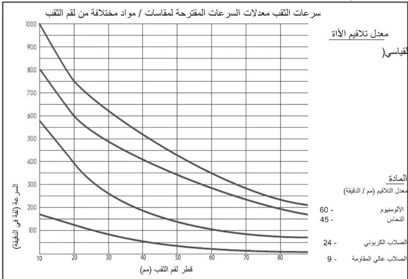
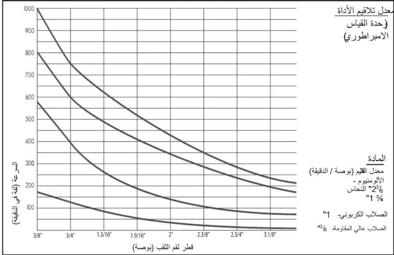
FEEDS AND SPEEDS
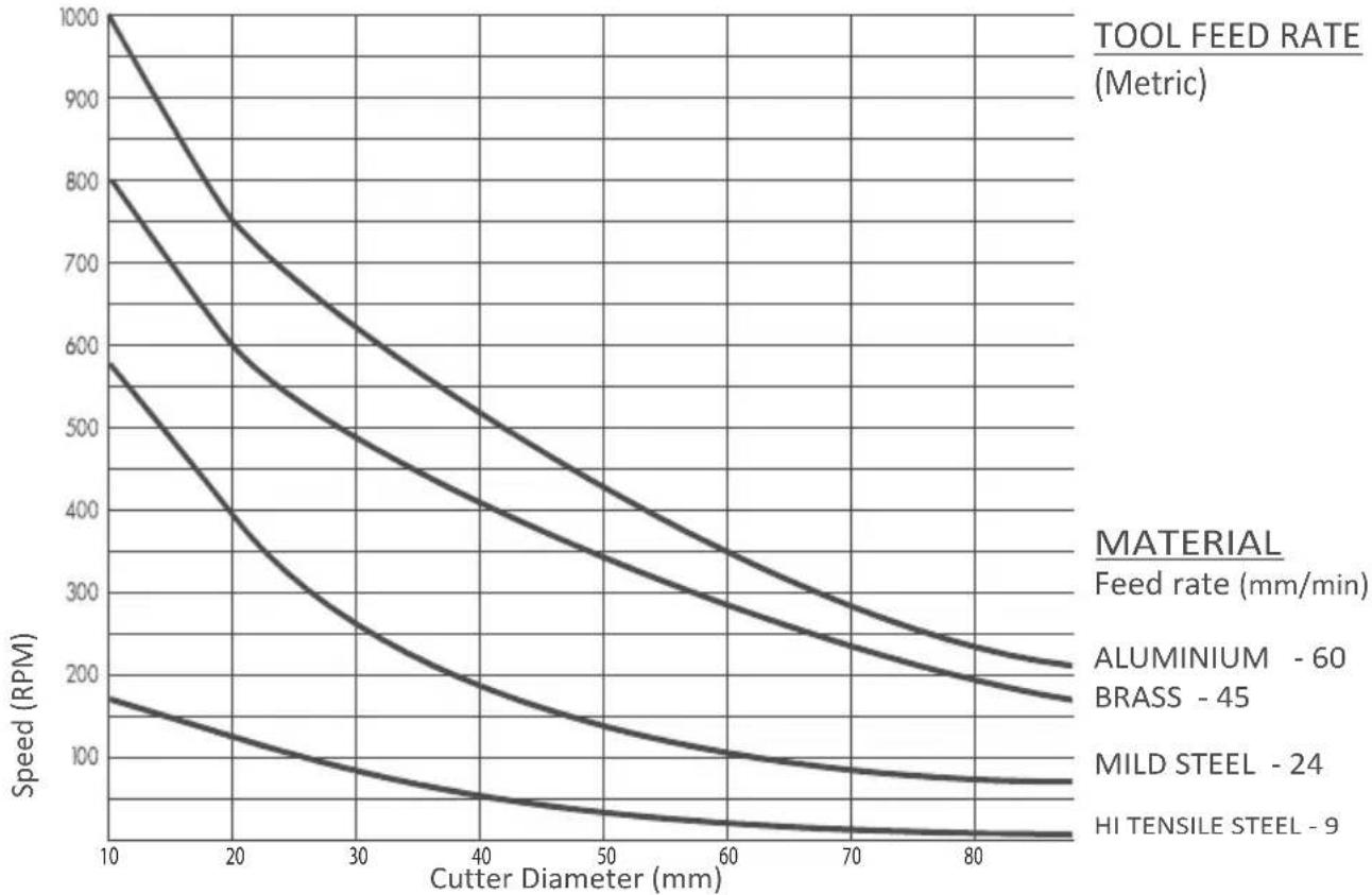
CUTTING SPEEDS Suggested speed rates for varying cutter sizes/materials
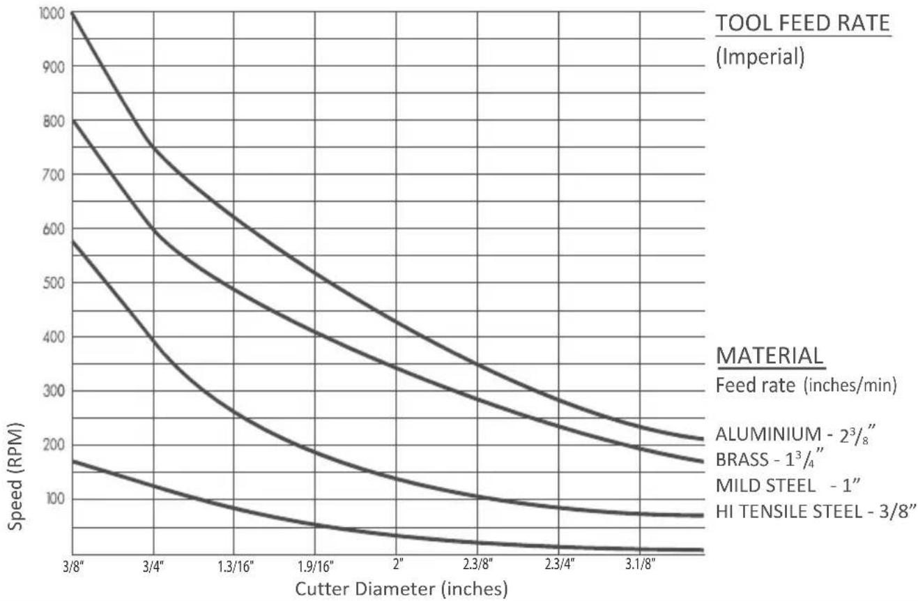
PLEASE NOTE: These figures are quoted as a star tig point. Actual performance will be dictated by material type, thickness and hardness, application, and cutter condition.
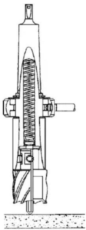
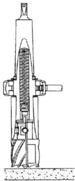
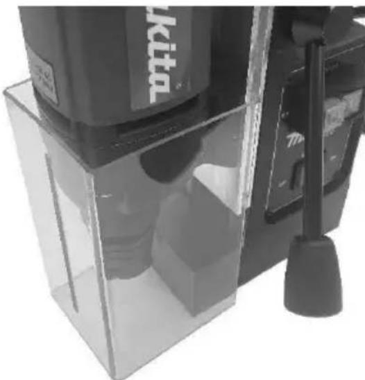
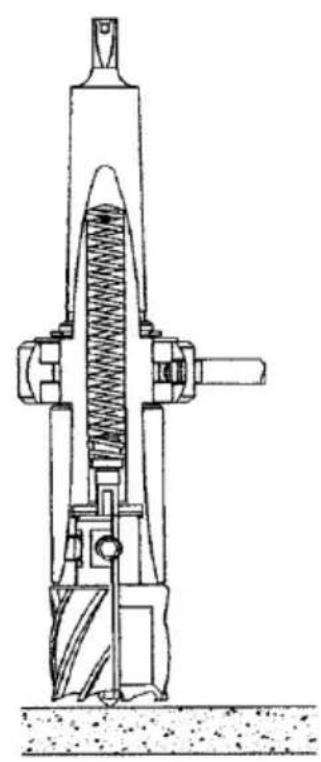
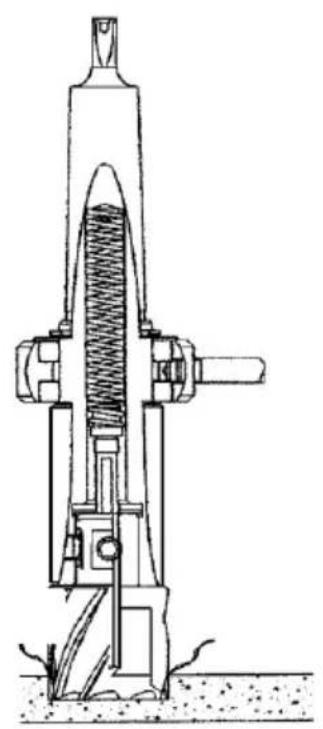
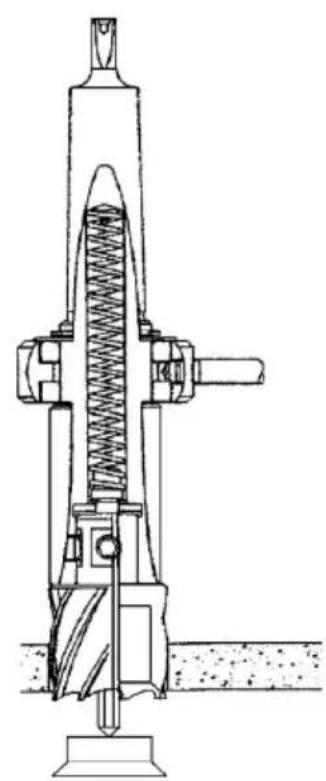
FITTING THE SAFETY GUARD
DRILL GUARD INSTRUCTIONS
Ensure drill unit is isolated from power supply. Fit guard to drill as shown.
When drilling, the guard should always be in contact with the surface being drilled. As the drill is lowered, the guard will rise in relation to the drill.

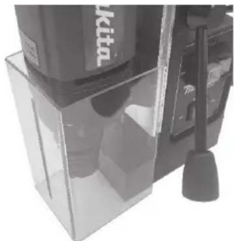
FITTING THE OIL BOTTLE
The cutting oil bottle is held in a sprung bracket attached to the top of the drill body. Fit the bracket by removing one of the cap screws from the top plate and replace the bolt through the fixing lug on the bottle bracket, tightening the bolt enough to allow some radial movement of the bracket. The coolant tube is a push fit into the self-seal gland at the base of the tap and a similar fitting on the lower arbor bracket.
FITTING THE SAFETY STRAP
The supplied safety strap should be used wherever possible as a safety precaution in the event of a power failure releasing the magnet; particularly in situations where the machine is clamped onto a vertical surface or in an inverted position.
SAFETY STRAP INSTRUCTIONS
When the machine has been clamped to the workpiece in the correct position for drilling, the strap should be fed through the channel between the body of the drill and the magnet, then passed around a substantial part of the workpiece. The free end should then be passed through the buckle, pulled tight and locked.
Once the cut is complete, the strap should be released, and the machine supported before the magnet is disengaged.
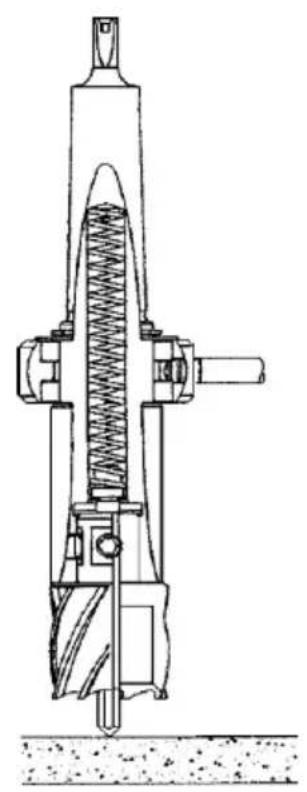
FITTING THE CUTTER
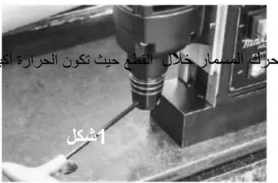
Ensure power is off before working on the machine. Insertion of pilot pin
- The pilot pin is used to both center the cutter and to eject the slug on completion of the cut. It has a flat side. to allow coolant to run down to reach the center of the cut where the heat is greatest. Slide the pin through the hole in the center of the cutter shank.
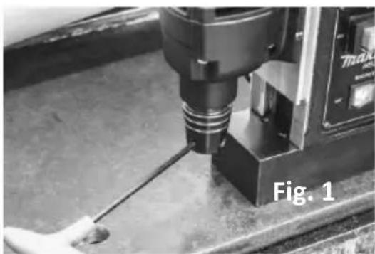
FITTING THE CUTTER
Fig 1.
To insert the cutter in the arbor, first loosen the grab screws, using an M5 hexagonal wrench. Ensure the grab screws are sufficiently loose enough to allow the shank of the cutter to enter freely.
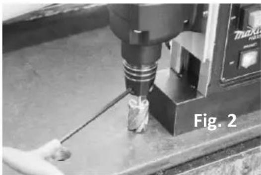
Fig 2.
Ensure the drive flats on the cutter shank are fully aligned with the two grab screws in the machine arbor.
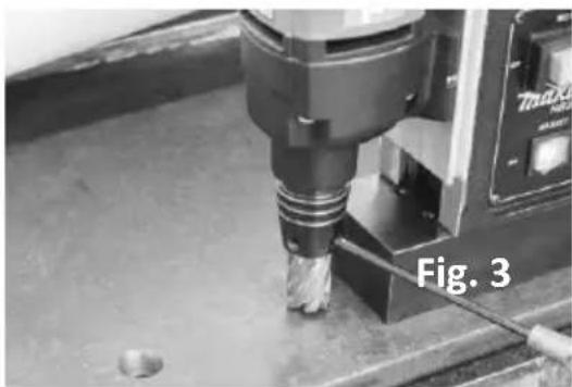
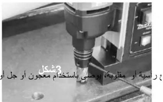
Fig 3.
Ensuring the shank of the cutter is fully inserted inside the arbor, tighten the grub screws fully to give the cutter a secure fitting inside the arbor.
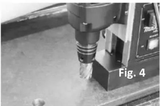
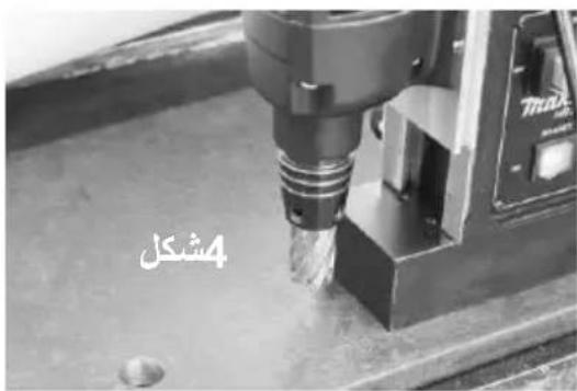
Fig 4.
The cutter is now ready for use.
FIT THE SAFTY STRAP
APPLYING COOLANT
- Cutting oil ensures longer cutter life and enables the slug to be ejected cleanly.
- Oil will be automatically delivered to the cutter when the cut commences
- When cutting on vertical surfaces or upside down, cutting paste, gel or foam is recommended. It is best applied inside the cutter before drilling.
N.B. Safety strap and guards have been omitted from the photo's for clarity.
OPERATION

1) Power
Ensure power to the drill and the drill is safe to operate.

2) Magnet ON
To turn the magnet ON or OFF, use the magnet switch as pictured.

3) Motor ON
B
Press the GREEN Switch to turn the motor on. Proceed with cutting - following all safety guidelines...

4) Motor OFF
To stop the motor press the RED switch. The motor will stop and the magnet will remain on.
Go back to step 3 to start over.
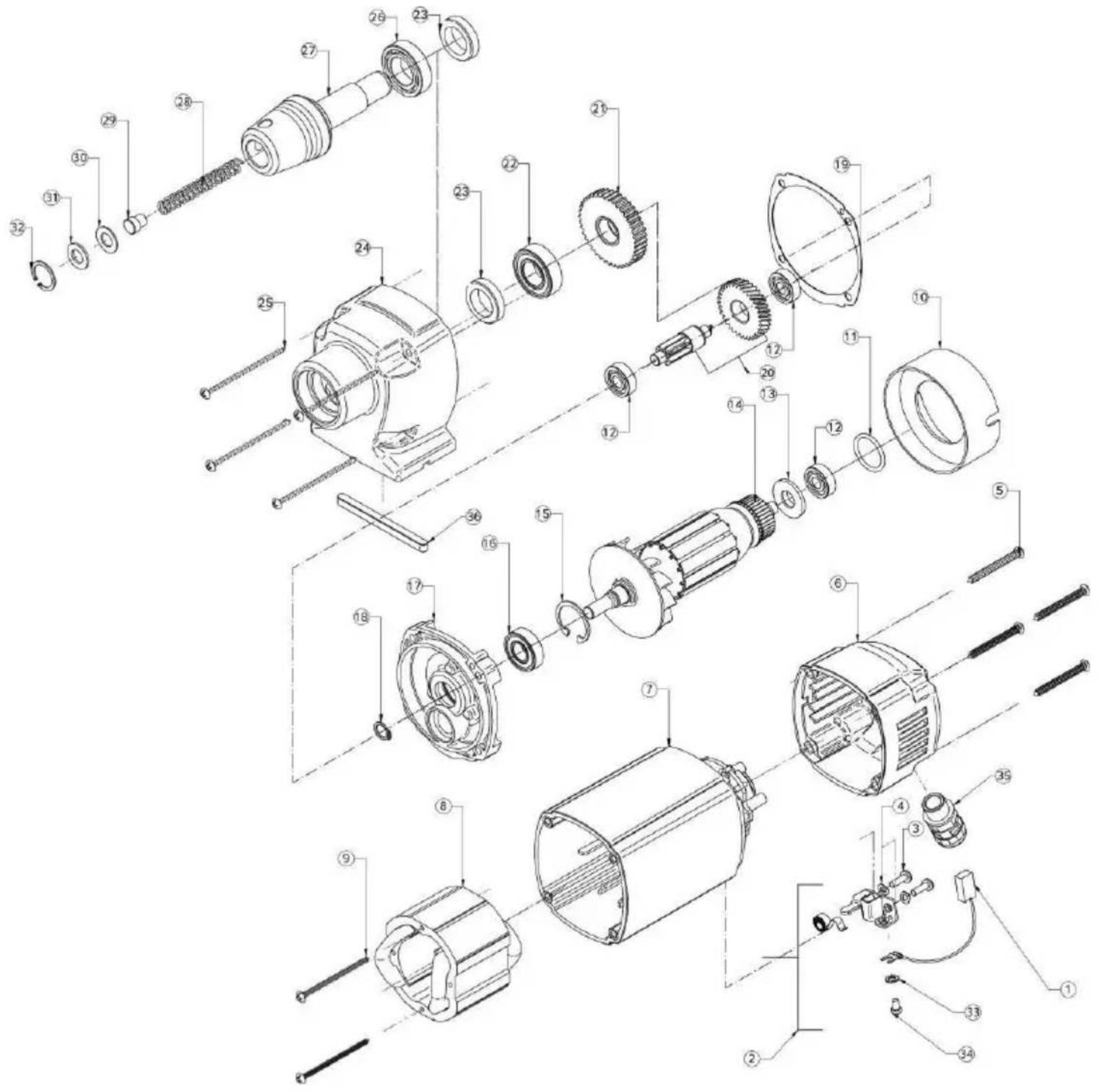
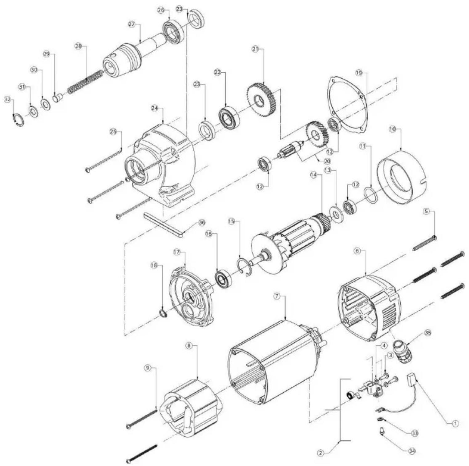
| Nr. | Description | Qty | Part No |
| 1 | CARBON BRUSH ASSY. 6.3X10X18 | 2 | EBD002 |
| 2 | BRUSH HOLDER ASSY. | 2 | EBD001 |
| 3 | SCREW M4 X 12 | 2 | EBD003 |
| 4 | SPRING WASHER M4 | 2 | EBD004 |
| 5 | PHILIPS HEAD SELF-TAP SCREW 4.8X45 | 4 | EBD005 |
| 6 | BACK COVER | 1 | EIB527 |
| 7 | FIELD COIL CASING | 1 | EIB526 |
| 8 | FIELD COIL ASSY 110V | 1 | EBD008-A |
| FIELD COIL ASSY 230V | 1 | EBD008-B | |
| 9 | PHILIPS HEAD SELF - TAP SCREW 3.9X60 | 2 | EBD009 |
| 10 | BAFFE | 1 | EBD010 |
| 11 | O RING | 1 | EBD011 |
| 12 | BALL BEARING (8-22-7) 608 2Z | 3 | UDC022 |
| 13 | DUST WASHER | 1 | EBD012 |
| 14 | ARMATURE ASSY 110V | 1 | EBD013-A |
| ARMATURE ASSY 230V | 1 | EBD013-B | |
| 15 | CIRCLIP 28MM X 1.2 B TYPE | 1 | EBD014 |
| 16 | BALL BEARING (12-28-8) 6001 2Z | 1 | UDC023 |
| 17 | GEAR CASE COVER | 1 | EBD015 |
| 18 | CIRCLIP 10MM X 1 A TYPE | 1 | EBD016 |
| 19 | GASKET | 1 | EBD017 |
| 20 | INTER SHAFT ASSY. | 1 | EBD018 |
| 21 | SPINDLE GEAR | 1 | EBD019 |
| 22 | BALL BEARING (17-35-10) 6003 2RS | 1 | UDC004 |
| 23 | OIL SEAL 20-30-7 B TYPE | 2 | EBD020 |
| 24 | GEAR CASE | 1 | EBD021 |
| 25 | PHILIPS HEAD SELF-TAP SCREW 4.8 X 60 | 4 | EBD022 |
| 26 | BALL BEARING 6904 2RS | 1 | EBD025 |
| 27 | ARBOR BODY. | 1 | EIB528 |
| 28 | ARBOR SPRING | 1 | EBD026 |
| 29 | ARBOR EJECTION PLUG | 1 | EBD027 |
| 30 | ARBOR WASHER | 1 | EBD028 |
| 31 | ARBOR RUBBER WASHER | 1 | EBD029 |
| 32 | ARBOR CIRCLIP | 1 | EBD030 |
| 33 | CARBON BRUSH WASHER | 2 | EBD031 |
| 34 | CARBON BRUSH FIXING SCREW | 2 | EBD032 |
| 35 | PG9 PUSH FIT GLAND | 1 | 40025 |
| 36 | MOTOR LOCATING KEY | 1 | M1019 |

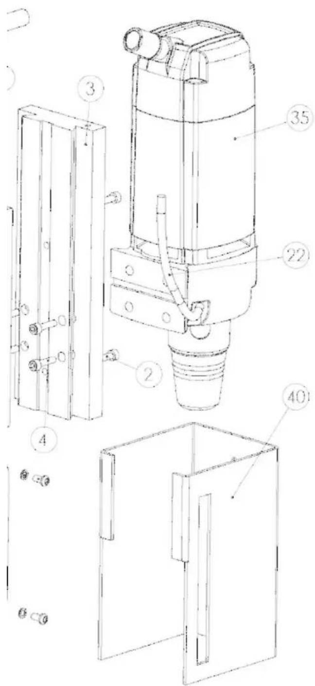
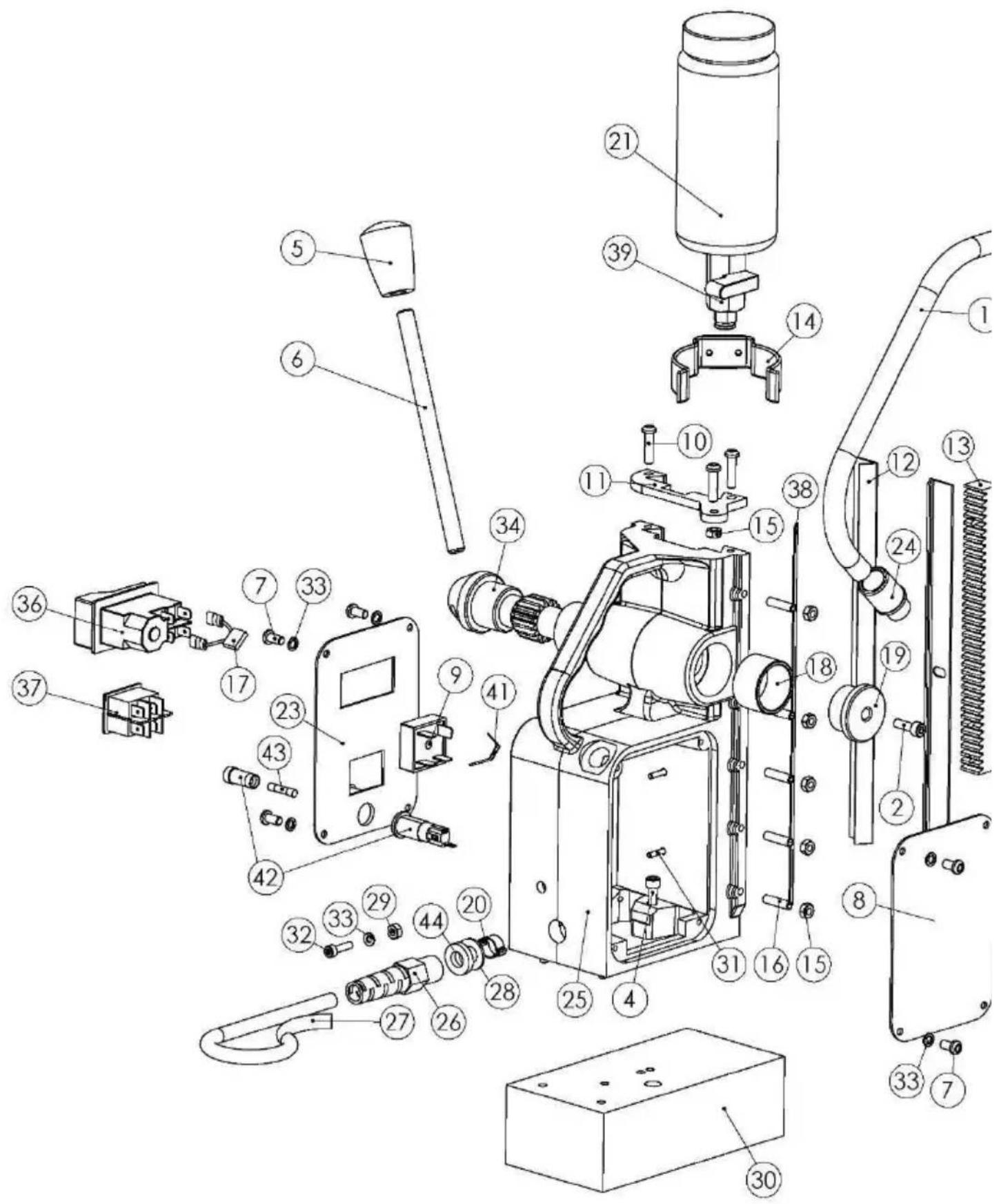
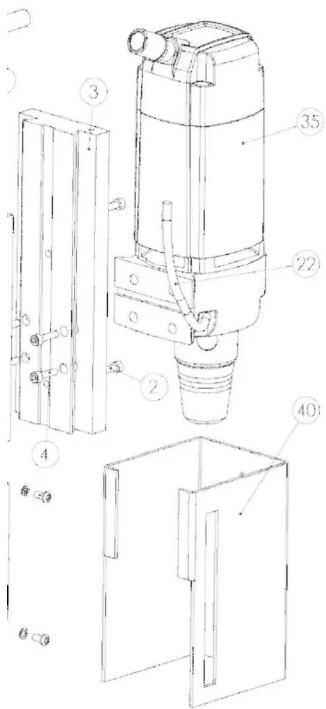
HB350 STAND PARTS
| Nr. | Description | Qty | Part No |
| 1 | CONDUIT (large dia 12mm) - PMA-PCLT-10B.50 | 1 | M0443 |
| 2 | M6 X 16 CAP HEAD SCREW | 3 | SC616CAP |
| 3 | SLIDE HB350 MAKITA | 1 | M1000 |
| 4 | M6 X 25 CAP HEAD SCREW | 7 | SC625CAP |
| 5 | HANDLE KNOB (10mm KNOCK ON) | 3 | M0841 |
| 6 | 10MM X 130MM HANDLE (SMALL) | 3 | BD043 |
| 7 | M4 X 6 BUTTON HEAD SCREW | 8 | SC46BUT |
| 8 | WARNING PLATE MAKITA HB350 CE JAPAN | M1002 | |
| WARNING PLATE MAKITA HB350 CE BELGIUM | M1003 | ||
| WARNING PLATE MAKITA HB350 CSA JAPAN | M1014 | ||
| WARNING PLATE MAKITA HB350 UKCA UK | M1018 | ||
| WARNING PLATE MAKITA HB350 RCM AUSTRALIA | M1021 | ||
| 9 | 25A - BRIDGE RECTIFIER (395-4310) | 1 | M0401 |
| 10 | M5 X 16 CAP HEAD SCREW | 3 | SC516CAP |
| 11 | OILFEED TOP BRACKET - (MB30 BODY) | 1 | M0811A |
| 12 | BRASS RAIL (MB30) | 2 | M0101 |
| 13 | RACK (MB30) | 1 | M0831 |
| 14 | OIL CUP RETAINING CLIP COMPLETE | 1 | 10076C |
| 15 | M5 NYLOC | 6 | 10085B |
| 16 | M5X25 KNURLED POINT GRUB SCREW | 5 | 10085A |
| 17 | CAPACITOR | 1 | RD43118 |
| 18 | BUSH (PINION) - 33 X 28 X 20 OILITE BUSH | 2 | M0081 |
| 19 | PINION END CAP - DEEP | 1 | M0072 |
| 20 | O CLIP 8-11 BOCLIP8/11 | 1 | RD47179 |
| 21 | D5000 OIL CUP ASSEMBLY | 1 | 30046A |
| 22 | U-06040(30MC) 6MM X 4MM CLEAR POLYURETHANE TUBE | 1 | BD029 |
| 23 | MAKITA HB350 CONTROL PANEL PLATE | 1 | M1001 |
| 24 | M16 PUSH FIT GLAND - PMA BVND-M160GT | 1 | 40026 |
| 25 | MB30 BODY BLACK | 1 | M0001BLK |
| 26 | M16 PIGTAIL GLAND COMPLETE WITH LOCK NUT - BBSM 16 | 1 | 10231 |
| 27 | USA CABLE - 14 GAUGE - 3M - AB-CAB-870 | CABL03 | |
| EUROPEAN CABLE C/W MOULD PLUG - AB-CAB-876 - 3M | CABL04 | ||
| MAKITA BRAZIL CABLE C/W PLUG 220V - 3M | CABL05 | ||
| 3MTR-110V MAINS LEAD BLACK C/W IND PLUG | CABL06 | ||
| ARGENTINA CABLE C/W PLUG - 230V - 3M | CABL08 | ||
| AUS/NZ-3M MAINS CABLE C/W MOULDED PLUG-AB-CAB-866 | CABL09 | ||
| 28 | M8 WASHER FOR ARBOR INTERNAL | 1 | RD47187 |
| 29 | M4 BRASS NUT | 1 | NUT-M4-B |
| 30 | HB350 MAGNET BASE | 1 | M1020 |
| 31 | M4 X 6 SLOTTED CSK MC SCREW - BZP | 5 | SC46CSK |
| 32 | M4 X 12 CSK MC SCREW - BRASS | 1 | SC412CSK-B |
| 33 | M4 SHAKE PROOF WASHER-BZP-WSH-227-004-ZC221 | 9 | SPWR-M4 |
| 34 | PINION - (SMALL) | 1 | M0041 |
| 35 | EIBENSTOCK BHM35 DRILL UNIT - 110V MAKITA BLUE | EIB522 | |
| EIBENSTOCK BHM35 DRILL UNIT - 230V MAKITA BLUE | EIB523 | ||
| 36 | DRILL STOP/START SWITCH - 110V - KJD17F/120V/50HZ - | NCP001 | |
| DRILL STOP/START SWITCH - 230V - KJD17F-230V-50HZ - | NCP002 | ||
| 37 | MAGNET SWITCH - NCP PANEL - B418CG00000 | 1 | NCP006 |
| 38 | G.F.S. (MB30) | 1 | M0441 |
| 39 | 1/8 BSP-6MM BLACK PUSH FIT | 1 | 50015 |
| 40 | GUARD TO SUIT NEW UNI 1 MBQ35N/EQ35N/EBM35 | 1 | VISO18 |
| 41 | 318-565 VARISTOR (V150LA10A) | W18XC522 | |
| VARISTOR HIGHSURGE 20MM 275 VRMS | W18XC521 | ||
| 42 | 248-447 FUSE HOLDER | 1 | W18XC511 |
| 43 | 2A FUSE (RAPID 26-2469) | 1 | W18XC512 |
| 44 | WASHER SMBK1869836HPU | 1 | UODO09 |
EC Declaration of Conformity
We as the manufacturers Makita Europe N.V.
Business address Jan-Baptist Vinkstraat 2
3070 Kortenberg
BELGIUM
Authorize Hiroshi Tsujimura for the compilation of the technical file and declare under our sole responsibility that the product(s);
Designation Magnetic Drill
Designation of Type(s) HB350
Fulfills all the relevant provisions of 2006/42/EC
and also fulfills all the relevant provisions of the following EC/EU
Directives:
- 2014/30/EU
- 2011/65/EU
and are manufactured in accordance with the following Harmonised Standards:
EN 62841-1:2015, EN ISO 12100:2010, EN 61000-6-2:2005, EN 61000-6-4:2007+A1:2011,
EN 61000-3-2:2014, EN 61000-3-3:2013, EN IEC 63000:2018
Place and date of declaration: Kortenberg, Belgium, 12.2.2021
Responsible person: Hiroshi Tsujimura
A
Director - Makita Europe N.V.
BEVOR SIE BEGINNEN
1) Power

Ensure power to the drill and the drill is safe to operate.
2) Magnet ON

To turn the magnet ON or OFF, use the magnet switch as pictured.
3) Motor ON

Press the GREEN Switch to turn the motor on. Proceed with cutting - following all safety guidelines...
4) Motor OFF

To stop the motor press the RED switch. The motor will stop and the magnet will remain on.
Go back to step 3 to start over.
Ensure power to the drill and the drill is safe to operate.

2) Magnet ON
To turn the magnet ON or OFF, use the magnet switch as pictured.

3) Motor ON
Press the GREEN Switch to turn the motor on. Proceed with cutting - following all safety guidelines...

4) Motor OFF
To stop the motor press the RED switch. The motor will stop and the magnet will remain on.
Go back to step 3 to start over.
PIÉCES DU MOTEUR HB350

| N° | Description | Qtt | Référence |
| 1 | ENSEMBLE DE BROSSES DE CARBONE 6,3X10X18 | 2 | EBD002 |
| 2 | ENSEMBLE PORTE-BROSSE | 2 | EBD001 |
| 3 | VIS M4 X 12 | 2 | EBD003 |
| 4 | RONDELLÉ ÉLASTIQUE M4 | 2 | EBD004 |
| 5 | VIS AUTO-TARAUDEUSE À Tête PHILIPS 4,8 X 45 | 4 | EBD005 |
| 6 | COUVERCLE ARRÈRE | 1 | EIB527 |
| 7 | BOÎTIER DE BOBINE DE CHAMP | 1 | EIB526 |
| 8 | ENSEMBLE BOBINE DE CHAMP 110V | 1 | EBD008-A |
| ENSEMBLE BOBINE DE CHAMP 230V | 1 | EBD008-B | |
| 9 | VIS AUTO-TARAUDEUSE À Tête PHILIPS 3,9 X 60 | 2 | EBD009 |
| 10 | DéFLECTEUR | 1 | EBD010 |
| 11 | JOINT TORIQUE | 1 | EBD011 |
| 12 | ROULEMENT À BILLE (8-22-7) 608 2Z | 3 | UDC022 |
| 13 | RONDELLÉ DE POUSSIÈRE | 1 | EBD012 |
| 14 | ENSEMBLE ARMATURE 110V | 1 | EBD013-A |
| ENSEMBLE ARMATURE 230V | 1 | EBD013-B | |
| 15 | CIRCLIP 28MM X 1,2 TYPE B | 1 | EBD014 |
| 16 | ROULEMENT À BILLE (12-28-8) 6001 2Z | 1 | UDC023 |
| 17 | COUVERCLE DE CARTER D'ENGRENAGE | 1 | EBD015 |
| 18 | CIRCLIP 10MM X 1 TYPE A | 1 | EBD016 |
| 19 | JOINT D'ÉTANCHÉITÉ | 1 | EBD017 |
| 20 | ENSEMBLE INTER-ARBRES | 1 | EBD018 |
| 21 | ENGRENAGE À BROCHE | 1 | EBD019 |
| 22 | ROULEMENT À BILLE (17-35-10) 6003 2RS | 1 | UDC004 |
| 23 | JOINT D'ÉTANCHÉITÉ À L'HUILLE 20-30-7 TYPE B | 2 | EBD020 |
| 24 | CARTER D'ENGRENAGE | 1 | EBD021 |
| 25 | VIS AUTO-TARAUDEUSE À Tête PHILIPS 4,8 X 60 | 4 | EBD022 |
| 26 | ROULEMENT À BILLE 6904 2RS | 1 | EBD025 |
| 27 | CORPS DE MANDRIN | 1 | EIB528 |
| 28 | RESSORT DE MANDRIN | 1 | EBD026 |
| 29 | BOUCHON D'ÉJECTION DU MANDRIN | 1 | EBD027 |
| 30 | RONDELLÉ DE MANDRIN | 1 | EBD028 |
| 31 | RONDELLÉ DE MANDRIN EN CAOUTCHOUC | 1 | EBD029 |
| 32 | CIRCLIP DE MANDRIN | 1 | EBD030 |
| 33 | RONDELLÉ DE BROSSE DE CARBONE | 2 | EBD031 |
| 34 | VIS DE FIXATION DE BROSSE DE CARBONE | 2 | EBD032 |
| 35 | PRESSE-ÉTOUPE PG9 | 1 | 40025 |
| 36 | CLÉ DE LOCALISATION DU MOTEUR | 1 | M1019 |
PIÉCES DÉTACHÉES HB350

| N° | Descripion | Q# | Référence |
| 1 | CONDUIT (grand dia. 12mm) - PMA-PCLT-10B.50 | 1 | M0443 |
| 2 | VIS À TÉTE CYLINDRIQUE M6 X 16 | 3 | SC616CAP |
| 3 | GISSIÈRE HB350 MAKITA | 1 | M1000 |
| 4 | VIS À TÉTE CYLINDRIQUE M6 X 25 | 7 | SC625CAP |
| 5 | BOUTON DE POIGNÉE (10mm À ENFONCER) | 3 | M0841 |
| 6 | POIGNÉE 10MM X 130MM (PETITE) | 3 | BD043 |
| 7 | VIS À TÉTE BOMBÉE M4 X 6 | 8 | SC46BUT |
| 8 | PLAQUE D'AVERTISSEMENT MAKITA HB350 CE JAPON | M1002 | |
| PLAQUE D'AVERTISSEMENT MAKITA HB350 CE BELGIQUE | M1003 | ||
| PLAQUE D'AVERTISSEMENT MAKITA HB350 CSA JAPON | M1014 | ||
| PLAQUE D'AVERTISSEMENT MAKITA HB350 UKCA | M1018 | ||
| PLAQUE D'AVERTISSEMENT MAKITA HB350 RCM AUSTRAILIE | M1021 | ||
| 9 | PONT REDRESEUR - 25A (395-4310) | 1 | M0401 |
| 10 | VIS À TÉTE CYLINDRIQUE M5 X 16 | 3 | SC516CAP |
| 11 | SUPPORT SUPérieUR D'ALIMENTATION EN HUILE - (CORPS | 1 | M0811A |
| 12 | RAIL EN LAITON (MB30) | 2 | M0101 |
| 13 | CRÉMAILLÈRE (MB30) | 1 | M0831 |
| 14 | CLIP DE FIXATION DU FLACON D'HUILE | 1 | 10076C |
| 15 | NYLOC M5 | 6 | 10085B |
| 16 | VIS SANS TÉTE À POINTE MOLETÉE M5X25 | 5 | 10085A |
| 17 | CONDENSATEUR | 1 | RD43118 |
| 18 | BAGUE (PIGNON) - BAGUE EN OILITE 33 X 28 X 20 | 2 | M0081 |
| 19 | EMBOUT DE PIGNON - PROFOND | 1 | M0072 |
| 20 | COLLIER DE SERRAGE 8-11 BOCLIP8/11 | 1 | RD47179 |
| 21 | ENSEMBLE FLACON D'HUILE D5000 | 1 | 30046A |
| 22 | TUBE EN POLYURETHANE TRANSPARENT 6MM X 4MM U- | 1 | BD029 |
| 23 | PLAQUE DE PANNEAU DE COMMANDE MAKITA HB350 | 1 | M1001 |
| 24 | PRESSE-ÉTOUPE M16 - PMA BVND-M160GT | 1 | 40026 |
| 25 | CORPS NOIR MB30 | 1 | M0001BLK |
| 26 | PRESSE-ÉTOUPE EN TIRE-BOUCHON AVEC CONTRE-ÉCROU | 1 | 10231 |
| 27 | CABLE ÉTATS-UNIS - CALIBRE 14 - 3M - AB-CAB-870 | CABLO3 | |
| CABLE EUROPE AVEC FICHE À BROCHES - AB-CAB-876 - 3M | CABLO4 | ||
| CABLE BRESIL MAKITA AVEC FICHE 220V - 3M | CABLO5 | ||
| CABLE SECTEUR 3MTR-110V NOIR AVEC FICHE | CABLO6 | ||
| CABLE ARGENTINE AVEC FICHE 230V - 3M | CABLO8 | ||
| CABLE SECTEUR AUSTRALIE/NZ-3M AVEC FICHE À BROCHES-AB CAB_866 | CABLO9 | ||
| 28 | RONDELLE M8 POUR MANDRIN INTERNE | 1 | RD47187 |
| 29 | ÉCROU EN LAITON M4 | 1 | NUT-M4-B |
| 30 | BASE MAGNETIQUE HB350 | 1 | M1020 |
| 31 | VIS À FENTE CSK MC M4 X 6 - BZP | 5 | SC46CSK |
| 32 | VIS CSK MC M4 X 12 - LAITON | 1 | SC412CSK-B |
| 33 | RONDELLE ANTI-VIBRATION M4-BZP-WSH-227-004-ZC221 | 9 | SPWR-M4 |
| 34 | PIGNON - (PETIT) | 1 | M0041 |
| 35 | PERCEUSE EIBENSTOCK BHM35 - 110V MAKITA BLEUE | EIB522 | |
| PERCEUSE EIBENSTOCK BHM35 - 230V MAKITA BLEUE | EIB523 | ||
| 36 | INTERRUPTEUR MARCHE/ARRÊT DE LA PERCEUSE - 110V | NCP001 | |
| INTERRUPTEUR MARCHE/ARRÊT DE LA PERCEUSE - 230V | NCP002 | ||
| 37 | INTERRUPTEUR MAGNETIQUE - PANNEAU NCP - | 1 | NCP006 |
| 38 | G.F.S. (MB30) | 1 | M0441 |
| 39 | RACCORD RAPIDE NOIR 1/8 BSP 6MM | 1 | 50015 |
| 40 | PROTECTION D'ADAPTATION NEW UNI 1 | 1 | VISO18 |
| 41 | VARISTOR 318-565 (V150LA10A) | W18XC522 | |
| VARISTOR HAUTE TENSION 20MM 275 VRMS | W18XC521 | ||
| 42 | PORTE-FUSIBLE 248-447 | 1 | W18XC511 |
| 43 | FUSIBLE 2A (RAPIDE 26-2469) | 1 | W18XC512 |
| 44 | RONDELLE SMBK1869836HPU | 1 | JOD009 |
ORIGINAL
HSS frees
TCT frees
Boorkop
BEOOGD GEBRUIK
HET VEILIGHEIDSSCHERM PLAATSEN
INSTRUCTIES BOORSCHERM
Ensure power to the drill and the drill is safe to operate.

2) Magnet ON
To turn the magnet ON or OFF, use the magnet switch as pictured.

3) Motor ON
Press the GREEN Switch to turn the motor on. Proceed with cutting - following all safety guidelines...

4) Motor OFF
To stop the motor press the RED switch. The motor will stop and the magnet will remain on.
Go back to step 3 to start over.

| Nr. | Beschrijving | Aantal | Onderdeelnr. |
| 1 | KOOLSTOF BORSTEL ASSEMBLAGE 6.3X10X18 | 2 | EBD002 |
| 2 | BORSTELHOUDER | 2 | EBD001 |
| 3 | SCHROEF M4 X 12 | 2 | EBD003 |
| 4 | VEERRING M4 | 2 | EBD004 |
| 5 | LENSKOPSCHROEF 4.8X45 | 4 | EBD005 |
| 6 | ACHTERBESCHERMING | 1 | EIB527 |
| 7 | VELDMAGNEETBEHUIZING | 1 | EIB526 |
| 8 | VELDMAGNEET ASSEMBLAGE 110V | 1 | EBD008-A |
| VELDMAGNEET ASSEMBLAGE 230V | 1 | EBD008-B | |
| 9 | LENSKOPSCHROEF 3.9X60 | 2 | EBD009 |
| 10 | STUWSCHIJF | 1 | EBD010 |
| 11 | O-RING | 1 | EBD011 |
| 12 | KOGELLAGER (8-22-7) 608 2Z | 3 | UDC022 |
| 13 | STOF SLUITRING | 1 | EBD012 |
| 14 | ARMATUUR ASSEMBLAGE 110V | 1 | EBD013-A |
| ARMATUUR ASSEMBLAGE 230V | 1 | EBD013-B | |
| 15 | BORGVEER 28MM X 1.2 B TYPE | 1 | EBD014 |
| 16 | KOGELLAGER (12-28-8) 6001 2Z | 1 | UDC023 |
| 17 | AFDEKKING KETTINGKAST | 1 | EBD015 |
| 18 | BORGVEER 10MM X 1 A TYPE | 1 | EBD016 |
| 19 | PAKKING | 1 | EBD017 |
| 20 | INTER AS ASSEMBLAGE | 1 | EBD018 |
| 21 | SPINDELAANDRIJVING | 1 | EBD019 |
| 22 | KOGELLAGER (17-35-10) 6003 2RS | 1 | UDC004 |
| 23 | OLIE-AFDICHTING 20-30-7 B TYPE | 2 | EBD020 |
| 24 | KETTINGKAST | 1 | EBD021 |
| 25 | LENSKOPSCHROEF 4.8X60 | 4 | EBD022 |
| 26 | KOGELLAGER 6904 2RS | 1 | EBD025 |
| 27 | SPANDOORN | 1 | EIB528 |
| 28 | SPANDOORN VEER | 1 | EBD026 |
| 29 | SPANDOORN UITWERPPLUG | 1 | EBD027 |
| 30 | SPANDOORN SLUITRING | 1 | EBD028 |
| 31 | SPANDOORN RUBBER SLUITRING | 1 | EBD029 |
| 32 | SPANDOORN BORGVEER | 1 | EBD030 |
| 33 | KOOLSTOF BORSTEL SLUITRING | 2 | EBD031 |
| 34 | KOOLSTOF BORSTEL FIXERSCHROEF | 2 | EBD032 |
| 35 | PG9 PERSWARTEL | 1 | 40025 |
| 36 | MOTORLOCATIONSLEUTEL | 1 | M1019 |

HB350 STATIEFONDERDELEN
| Nr. | Beschrijving | Aanta | Onderdeeln. |
| 1 | LEIDING (grote diameter 12 mm) - PMA-PCLT-10B.50 | 1 | M0443 |
| 2 | M6 X 16 DOP KOPSCHROEF | 3 | SC616CAP |
| 3 | SCHUIF HB350 MAKITA | 1 | M1000 |
| 4 | M6 X 25 DOP KOPSCHROEF | 7 | SC625CAP |
| 5 | HANDVATKNOP (10mm VASTHAMEREN) | 3 | M0841 |
| 6 | 10 X 130 MM HANDGREEP (KLEIN) | 3 | BD043 |
| 7 | M4 X 6 KNOOPKOPSCHROEF | 8 | SC46BUT |
| 8 | WAARSCHUWINGSPLAAT MAKITA HB350 CE JAPAN | M1002 | |
| WAARSCHUWINGSPLAAT MAKITA HB350 CE BELGIÉ | M1003 | ||
| WAARSCHUWINGSPLAAT MAKITA HB350 CSA JAPAN | M1014 | ||
| WAARSCHUWINGSPLAAT MAKITA HB350 UKCA VK | M1018 | ||
| WAARSCHUWINGSPLAAT MAKITA HB350 RCM AUSTRALIÉ | M1021 | ||
| 9 | 25A - BRUGGELIJKRICHTER (395-4310) | 1 | M0401 |
| 10 | M5 X 16 DOP KOPSCHROEF | 3 | SC516CAP |
| 11 | OLEAANZET BOVENSTE BEUGEL - (MB30 ELEMENT) | 1 | M0811A |
| 12 | MESSING RAIL (MB30) | 2 | M0101 |
| 13 | REK (MB30) | 1 | M0831 |
| 14 | OLIEKOP BEVESTIGINGSKLEM VOLLEDIG | 1 | 10076C |
| 15 | M5 NYLOC | 6 | 10085B |
| 16 | M5X25 GEKARTELDE STIFTTAPBOUT | 5 | 10085A |
| 17 | CONDENSATOR | 1 | RD43118 |
| 18 | BUS (PINION) - 33 X 28 X 20 OLIETBUS | 2 | M0081 |
| 19 | PINION EINDDDOP- DIEP | 1 | M0072 |
| 20 | O CLIP 8-11 BOCLIP8 / 11 | 1 | RD47179 |
| 21 | D5000 OLIEKOP MONTAGE | 1 | 30046A |
| 22 | U-06040 (30MC) 6 MM X 4 MM DOORZICTIGE POLYURETHAAN | 1 | BD029 |
| 23 | MAKITA HB350 BEDIENINGSPANIEL PLAAT | 1 | M1001 |
| 24 | M16 PERSWARTEL - PMA BVND-M160GT | 1 | 40026 |
| 25 | MB30 ELEMENT Zwart | 1 | M0001BLK |
| 26 | M16 PIGTAIL WARTEL COMPLEET MET BORGMOER - BBSM | 1 | 10231 |
| 27 | KABEL - 14 METER - 3M - AB-CAB-870 | CABLO3 | |
| EUROPESE KABEL C/W VORMSTEKKER - AB-CAB-876 - 3M | CABLO4 | ||
| MAKITA BRAZILIE KABEL MET STEKKER 220V - 3M | CABLO5 | ||
| 3MTR-110V STROOMKABEL Zwart C /W IND-STEKKER | CABLO6 | ||
| ARGENTINIÉ KABEL C/W STEKKER - 230V - 3M | CABLO8 | ||
| AUS / NZ-3M STROOMKABEL C /W GEGOTEN STEKKER- AB-CAB-866 | CABLO9 | ||
| 28 | M8 SPRINGVEER VOOR INTERNE SPANDOORN | 1 | RD47187 |
| 29 | M4 MessING MOER | 1 | MOER-M4-B |
| 30 | HB350 MAGNEETONDERSTEL | 1 | M1020 |
| 31 | M4 X 6 GESLEUFDE CSK MC-SCHROEF - BZP | 5 | SC46CSK |
| 32 | M4 X 12 CSK MC-SCHROEF - MESSING | 1 | SC412CSK-B |
| 33 | M4 SCHUDBESTENDIGE VEERRING-BZP-WSH-227-004-ZC221 | 9 | SPWR-M4 |
| 34 | PINION - (KLEIN) | 1 | M0041 |
| 35 | EIBENSTOCK BHM35 BOOR-EENHEID - 110V MAKITA BLAUW | EIB522 | |
| EIBENSTOCK BHM35 BOOR-EENHEID - 230V MAKITA BLAUW | EIB523 | ||
| 36 | BOOR STOP /START SCHAKELAAR - 110V - KJD17F / 120V / | NCP001 | |
| BOOR STOP /START SCHAKELAAR - 230V - KJD17F-230V- | NCP002 | ||
| 37 | MAGNEETSCHAKELAAR - NCP-PANELL - B418CG00000 | 1 | NCP006 |
| 38 | G.F.S. (MB30) | 1 | M0441 |
| 39 | 1/8 BSP-6MM Zwart PUSH FIT | 1 | 50015 |
| 40 | SCHERM VOOR NIEUWE UNI 1 MBQ35N / EQ35N / EBM35 | 1 | VISO18 |
| 41 | 318-565 VARISTOR (V150LA10A) | W18XC522 | |
| VARISTOR HIGHSURGE 20MM 275 VRMS | W18XC521 | ||
| 42 | 248-447 ZEKERINGHOUDER | 1 | W18XC511 |
| 43 | 2A ZEKERING (RAPID 26-2469) | 1 | W18XC512 |
| 44 | VEERRING SMBK1869836HPU | 1 | UOD009 |
ORIGINEEL
Ensure power to the drill and the drill is safe to operate.

2) Magnet ON
To turn the magnet ON or OFF, use the magnet switch as pictured.

3) Motor ON
Press the GREEN Switch to turn the motor on. Proceed with cutting - following all safety guidelines...

4) Motor OFF
To stop the motor press the RED switch. The motor will stop and the magnet will remain on.
Go back to step 3 to start over.

HB350 COMPONENTES DEL MOTOR
| N.° | Descripción | Cantidad | Referencia |
| 1 | CONJUNTO ESCOBILLA 6.3X10X18 | 2 | EBD002 |
| 2 | CONJUNTO SOPORTE ESCOBILLA | 2 | EBD001 |
| 3 | TORNILLO M4 x 12 | 2 | EBD003 |
| 4 | ARANDELA DE PRESIÑON M4 | 2 | EBD004 |
| 5 | TORNILLO AUTORROSCANTE PHILIPS 4.8x45 | 4 | EBD005 |
| 6 | CUBIERTA TRASERA | 1 | EIB527 |
| 7 | CARCASA BOBINA | 1 | EIB526 |
| 8 | CONJUNTO BOBINA 110 V | 1 | EBD008-A |
| CONJUNTO BOBINA 230V | 1 | EBD008-B | |
| 9 | TORNILLO AUTORROSCANTE PHILIPS 3.9X60 | 2 | EBD009 |
| 10 | AMORTIGUADOR RUIDO | 1 | EBD010 |
| 11 | JUNTA TÓRICA | 1 | EBD011 |
| 12 | RODAMIENTO DE BOLAS (8-22-7) 608 2Z | 3 | UDC022 |
| 13 | ARANDELA ANTIPOLVO | 1 | EBD012 |
| 14 | CONJUNTO INDUCIDO 110 V | 1 | EBD013-A |
| CONJUNTO INDUCIDO 230V | 1 | EBD013-B | |
| 15 | CIRCLIP 28MM x 1.2 TIPO B | 1 | EBD014 |
| 16 | RODAMIENTO DE BOLAS (12-28-8) 6001 2Z | 1 | UDC023 |
| 17 | TAPA CAJA TRANSMISión | 1 | EBD015 |
| 18 | CIRCLIP 10MM x 1 TIPO A | 1 | EBD016 |
| 19 | JUNTA | 1 | EBD017 |
| 20 | CONJUNTO EJE INTER | 1 | EBD018 |
| 21 | ENGRANAJE ROTATIVO | 1 | EBD019 |
| 22 | RODAMIENTO DE BOLAS (17-35-10) 6003 2RS | 1 | UDC004 |
| 23 | SELLO ACEITE 20-30-7 TIPO B | 2 | EBD020 |
| 24 | CAJA TRANSMISión | 1 | EBD021 |
| 25 | TORNILLO AUTORROSCANTE PHILIPS 4.8 X 60 | 4 | EBD022 |
| 26 | RODAMIENTO DE BOLAS 6904 2RS | 1 | EBD025 |
| 27 | CUERPO ÁRBOL | 1 | EIB528 |
| 28 | MUELLE ÁRBOL | 1 | EBD026 |
| 29 | TAPón EYECCION ÁRBOL | 1 | EBD027 |
| 30 | ARANDELA ÁRBOL | 1 | EBD028 |
| 31 | ARANDELA GOMA ÁRBOL | 1 | EBD029 |
| 32 | CIRCLIP ÁRBOL | 1 | EBD030 |
| 33 | ARANDELA ESCOBILLA | 2 | EBD031 |
| 34 | TORNILLO FIJACION ESCOBILLA | 2 | EBD032 |
| 35 | BOQUILLA PRESIÑON PG9 | 1 | 40025 |
| 36 | CHAVETA FIJACION MOTOR | 1 | M1019 |
Persona responsible: Hiroshi Tsujimura
A
Director - Makita Europe N.V.
ANTES DE COMEÇAR

Broca HSS
Broca TCT
- Porta-brocas
UTILIZACAO PREVISTA
Ensure power to the drill and the drill is safe to operate.

2) Magnet ON
To turn the magnet ON or OFF, use the magnet switch as pictured.

3) Motor ON
Press the GREEN Switch to turn the motor on. Proceed with cutting - following all safety guidelines...

4) Motor OFF
To stop the motor press the RED switch. The motor will stop and the magnet will remain on.
Go back to step 3 to start over.

| N.° | Descrição | Qtd. | N.° de peça |
| 1 | UNID. ESCOVA DE CARVÃO 6.3X10X18 | 2 | EBD002 |
| 2 | UNID. SUPORTE DA ESCOVA | 2 | EBD001 |
| 3 | PARAFUSO M4 X 12 | 2 | EBD003 |
| 4 | ARRUELA DE PRESSão M4 | 2 | EBD004 |
| 5 | PARAFUSO PHILIPS AUTORROSCANTE 4.8X45 | 4 | EBD005 |
| 6 | COBERTURA TRASEIRA | 1 | EIB527 |
| 7 | CARCAÇA DA BOBINA DE INDUÇÃO | 1 | EIB526 |
| 8 | UNID. BOBINA DE INDUÇÃO 110V | 1 | EBD008-A |
| UNID. BOBINA DE INDUÇÃO 230V | 1 | EBD008-B | |
| 9 | PARAFUSO PHILIPS AUTORROSCANTE 3.9X60 | 2 | EBD009 |
| 10 | DEFLETOR | 1 | EBD010 |
| 11 | O-RING | 1 | EBD011 |
| 12 | ROLAMENTO DE ESFERAS (8-22-7) 608 2Z | 3 | UDC022 |
| 13 | ANILHA ANTIPOEIRA | 1 | EBD012 |
| 14 | UNID. INDUZIDO 110V | 1 | EBD013-A |
| UNID. INDUZIDO 230V | 1 | EBD013-B | |
| 15 | ANEL ELASTICO 28MM X 1.2 TIPO B | 1 | EBD014 |
| 16 | ROLAMENTO DE ESFERAS (12-28-8) 6001 2Z | 1 | UDC023 |
| 17 | COBERTURA DA CAIXA DE ENGRENAGENS | 1 | EBD015 |
| 18 | ANEL ELASTICO 10MM X 1 TIPO A | 1 | EBD016 |
| 19 | VEDANTE | 1 | EBD017 |
| 20 | UNID. EIXO INTER. | 1 | EBD018 |
| 21 | ENGRENAGEM DO FUSO | 1 | EBD019 |
| 22 | ROLAMENTO DE ESFERAS (17-35-10) 6003 2RS | 1 | UDC004 |
| 23 | VEDANTE DO ÓLEO 20-30-7 TIPO B | 2 | EBD020 |
| 24 | CAIXA DE ENGRENAGENS | 1 | EBD021 |
| 25 | PARAFUSO PHILIPS AUTORROSCANTE 4.8 X 60 | 4 | EBD022 |
| 26 | ROLAMENTO DE ESFERAS 6904 2RS | 1 | EBD025 |
| 27 | ESTR. DA ÁRVORE | 1 | EIB528 |
| 28 | MOLA DA ÁRVORE | 1 | EBD026 |
| 29 | BUJÃO DE EJEÇÃO DA ÁRVORE | 1 | EBD027 |
| 30 | ANILHA DA ÁRVORE | 1 | EBD028 |
| 31 | ANILHA DE BORRACHA DA ÁRVORE | 1 | EBD029 |
| 32 | ANEL ELASTICO DA ÁRVORE | 1 | EBD030 |
| 33 | ANILHA DA ESCOVA DE CARVÃO | 2 | EBD031 |
| 34 | PARAFUSO DE FIXAZão DA ESCOVA DE CARVÃO | 2 | EBD032 |
| 35 | PG9 EMPANQUE DE ENCAIXE DE PRESSão | 1 | 40025 |
| 36 | CHAVE DE LOVALIZAZão DO MOTOR | 1 | M1019 |
PEÇAS DA COLUNA HB350

| N.° | Descrição | Qtd. | N.° de peça |
| 1 | CONDUTA (grande, diam. 12 mm) - PMA-PCLT-10B,50 | 1 | M0443 |
| 2 | M6 X 16 PARAFUSO DE CÂBEÇA CIÂINDRICA | 3 | SC616CAP |
| 3 | APOIO DESLIZANTE HB350 MAKITA | 1 | M1000 |
| 4 | M6 X 25 PARAFUSO DE CÂBEÇA CIÂINDRICA | 7 | SC625CAP |
| 5 | CABO DO PUNHO (10mm ENCAIXE DE PRESSÂ) | 3 | M0841 |
| 6 | 10MM X 130MM PUNHO (PEQUENO) | 3 | BD043 |
| 7 | M4 X 6 PARAFUSO DE CÂBEÇA REDONDA FENDIDA | 8 | SC46BUT |
| 8 | PLACA DE AVISO MAKITA HB350 CE JAPÂ | M1002 | |
| PLACA DE AVISO MAKITA HB350 CE BÉLGICA | M1003 | ||
| PLACA DE AVISO MAKITA HB350 CSA JAPÂ | M1014 | ||
| PLACA DE AVISO MAKITA HB350 RUCA RU | M1018 | ||
| PLACA DE AVISO MAKITA HB350 RCM AUSTRÁLIA | M1021 | ||
| 9 | 25A - RETIFICADOR EM PONTE (395-4310) | 1 | M0401 |
| 10 | M5 X 16 PARAFUSO DE CÂBEÇA CIÂINDRICA | 3 | SC516CAP |
| 11 | ABASTECIMENTO DE ÓLEO SUPORTE SUPERIOR - (MB30 | 1 | M0811A |
| 12 | CALHA DE BRONZE (MB30) | 2 | M0101 |
| 13 | CREMALHEIRA (MB30) | 1 | M0831 |
| 14 | ARO DE SUPORTE DO RESERVATÓRIO DO ÓLEO COMPLETE | 1 | 10076C |
| 15 | M5 NYLOC | 6 | 10085B |
| 16 | MSX25 PARAFUSO RECARTILHADO SEM CÂBEÇA | 5 | 10085A |
| 17 | CONDENSADOR | 1 | RD43118 |
| 18 | ANILHA (PINHÂ) - 33 X 28 X 20 ANILHA OILITE | 2 | M0081 |
| 19 | TAMPÂO DA ANILHA - FUNDO | 1 | M0072 |
| 20 | ARO DO ÓLEO 8-11 BOCLIP8/11 | 1 | RD47179 |
| 21 | D5000 UNID. RESERVATÓRIO DO ÓLEO | 1 | 30046A |
| 22 | U-06040(30MC) 6MM X 4MIM TUBO TRANSPARENTE DE | 1 | BD029 |
| 23 | MAKITA HB350 PLACA DO PAINEL DE CONTROLLO | 1 | M1001 |
| 24 | M16 EMPANQUE DE ENCAIXE DE PRESSÂ - PMA BVND- | 1 | 40026 |
| 25 | MB30 ESTRUTURA EM PRETO | 1 | M0001BLK |
| 26 | M16 EMPANQUE EM ESPIRAL COMPLETE COM PORCA DE | 1 | 10231 |
| 27 | CABO EUA - DIÂMETRO 14-3M - AB-CAB-870 | CABLO3 | |
| CABO EUROPEU C/ FÍCHA MOLDADA - AB-CAB-876 - 3M | CABLO4 | ||
| CABO MAKITA BRAZIL C/ FÍCHA 220V - 3M | CABLO5 | ||
| CABO DE REDE 3MTR-110V PRETO C/ FÍCHA IND. | CABLO6 | ||
| CABO ARGENTINA C/ FÍCHA - 230V - 3M | CABLO8 | ||
| CABO DE REDE AUS/NZ-3M C/ FÍCHA MOLDADA-AB-CAB-866 | CABLO9 | ||
| 28 | M8 ANILHA PARA ARVORE INTERNA | 1 | RD47187 |
| 29 | M4 PORCA DE BRONZE | 1 | NUT-M4-B |
| 30 | HB350 BASE MAGNÉTICA | 1 | M1020 |
| 31 | M4 X 6 PARAFUSO FENDIDO CSK MC - BZP | 5 | SC46CSK |
| 32 | M4 X 12 PARAFUSO CSK MC - BRONZE | 1 | SC412CSK-B |
| 33 | M4 ARRUELA DENTADA-BZP-WSH-227-004-ZC221 | 9 | SPWR-M4 |
| 34 | PINHÂ - (PEQUENO) | 1 | M0041 |
| 35 | UNIDADE PERFURAÇÃO EIBENSTOCK BHM35 - 110V MAKITA | EIB522 | |
| UNIDADE PERFURAÇÃO EIBENSTOCK BHM35 - 230V MAKITA | EIB523 | ||
| 36 | INTERRUPTOR ARRANQUE/PARAGEM DO BERBEQUIM - | NCP001 | |
| INTERRUPTOR ARRANQUE/PARAGEM DO BERBEQUIM - | NCP002 | ||
| 37 | INTERRUPTOR MAGNÉTICO - PAINEL NCP - B418CG00000 | 1 | NCP006 |
| 38 | G.F.S. (MB30) | 1 | M0441 |
| 39 | 1/8 BSP-6MM ENCAIXE DE PRESSÂ PRETO | 1 | 50015 |
| 40 | PROTEÇÂ ADEQUADA A NOVA UNI 1 | 1 | VIS018 |
| 41 | 318-565 VARISTOR (V150LA10A) | W18XC522 | |
| VARISTOR PICO 20MM 275 VRMS | W18XC521 | ||
| 42 | 248-447 PORTA-FUSÂVEIS | 1 | W18XC511 |
| 43 | FUSÂVEL 2A (RÂPIDO 26-2469) | 1 | W18XC512 |
| 44 | ANILHA SMBK1869836HPU | 1 | UOD009 |
Responsavel: Hiroshi Tsujimura
A
Diretor - Makita Europe N.V.
y
Jan-Baptist Vinkstraat 2
3070 Kortenberg
Hiroshi Tsujimura
y
HB350 (g)
2006/42/EC 1
y
2014/30/EU
2011/65/EU
ailll 1000
EN 62841-1:2015, EN ISO 12100:2010, EN 61000-6-2:2005,
EN 61000-6-4:2007+A1:2011,
EN 61000-3-2:2014, EN 61000-3-3:2013, EN IEC 63000:2018
Kortenberg, Belgium, 12.2.2021:
Hiroshi Tsujimura
9.
Makita Europe N.V. -
| الإستعمال | الإستعمال | الإستعمال |
| M0443 | 1 | PMA-PCLT-10B.50 (مaturity) (2012) |
| SC616CAP | 3 | M6 x 16 مصحيى بوراني مصحيى |
| M1000 | 1 | HB350 MAKITA商业信誉 |
| SC625CAP | 7 | M6 x 25 مصحيى بوراني مصحيى |
| M0841 | 3 | (عربية 10) مصحيى الحرفية |
| BD043 | 3 | (عربية 130) مصحيى الحرفية |
| SC46BUT | 8 | M4 x 6 مصحيى بوراني مصحيى |
| M1002 | MAKITA HB350 CE مصحيى نجاحس | |
| M1003 | MAKITA HB350 CE مصحيى نجCHASE | |
| M1014 | MAKITA HB350 CSA مصحيى نجCHASE | |
| M1018 | MAKITA HB350 UKCA | |
| M1021 | MAKITA HB350 RCM مصحيى نجCHASE | |
| M0401 | 1 | 4(310 - 395) مصحيى – مصحيى 25 |
| SC516CAP | 3 | M5 x 16 مصحيى بوراني مصحيى |
| M0811A | 1 | (MB30 مصحيى) |
| M0101 | 2 | (MB30) |
| M0831 | 1 | (MB30) |
| 10076C | 1 | السلامة الحرفية |
| 10085B | 6 | M5 مصحيى بوراني مصحيى |
| 10085A | 5 | MAKITA HB350 M5X25 |
| RD43118 | 1 | ### |
| M0081 | 2 | ### |
| M0072 | 1 | ### |
| RD47179 | 1 | 11/8 مصحيى مصحيى |
| 30046A | 1 | ### D5000 |
| BD029 | 1 | ### 4 x 6 U-06040(30MC) |
| M1001 | 1 | MAKITA HB350 |
| 40026 | 1 | M16-PMA BVND-M160GT مصحيى بوراني مصحيى |
| M0001BLK | 1 | ### MB30 |
| 10231 | 1 | BBSM 16 - مصحيى مصحيى |
| CABL03 | AB-CAB-870 - 3 - 14 | |
| CABL04 | AB-CAB-876 - 3 - مصحيى C/W | |
| CABL05 | ### C/W MAKITA BRAZIL | |
| CABL06 | ### C/W 3MTR-110 | |
| CABL08 | ### C/W-230 C/W | |
| CABL09 | AB-CAB-866### C/W### C/S### | |
| RD47187 | 1 | ### M8 |
| NUT-M4-B | 1 | M4### |
| M1020 | 1 | ### HB350 |
| SC46CSK | 5 | BZP - مصحيى CSK MC |
| SC412CSK-B | 1 | ### M4 X 12 CSK MC |
| SPWR-M4 | 9 | BZP-WSH-227-004-ZC221-### M4 |
| M0041 | 1 | ### |
| EIB522 | MAKITA### | |
| EIB523 | MAKITA### | |
| NCP001 | KJD17F/120V/50HZ### | |
| NCP002 | ### KJD17F-230### | |
| NCP006 | 1 | NPC - B418CG00000 |
| M0441 | 1 | (MB30) |
| 50015 | 1 | ### BSP-6 8/1 |
| VISO18 | 1 | MBQ35N/EO35N/EBM35 1### |
| W18XC522 | (V150LA10A) | |
| W18XC521 | VRMS 275 ### | |
| W18XC511 | 1 | ### 447-248 |
| W18XC512 | 1 | (2469-26###) |
| UOD009 | 1 | SMBK1869836HPU |
Ensure power to the drill and the drill is safe to operate.

2) Magnet ON
To turn the magnet ON or OFF, use the magnet switch as pictured.

3) Motor ON
Press the GREEN Switch to turn the motor on. Proceed with cutting - following all safety guidelines...

4) Motor OFF
To stop the motor press the RED switch. The motor will stop and the magnet will remain on.
Go back to step 3 to start over.
jll Jll jll l 11
- gill Jawa Jia
iic a jinall aol jy y 100 100 100 100 100 100 100
JSS
aaii jssgaae
aai 1
1
J 5
S ACD = S COD + S_ DCE
.2
i 1
jglsl
.3
J 1
Jolal Jolal Jolal Jolal Jolal
4
aai
jai jia jiu

2
.
i 1
j
aJlS sJolok Jolal jlaJdaiu bJus aJus Jus Jus Jus Jus Jus Jus Jus Jus Jus Jus Jus Jus Jus Jus Jus Jus Jus Jus Jus Jus Jus Jus Jus Jus Jus Jus Jus Jus Jus Jus Jus Jus Jus Jus Jus Jus Jus
e jll laiie Laiy pia 11
i iill jll all jall a b
alall paa jll oall jall
a b no j5 jg Jg ad jg wblizall g
Jds no jdl fjbd jd jd Jall
aab g klaa y
jll jll jll lal 2
J 1
11 11
i j
Jiai jai jai jai jai jai jai jai jai jai jai jai jai jai jai jai jai jai jai jai jai jai jai jai jai jai jai jai jai jai jai jai jai jai jai jai jai jai jai jai jai jai jai jai jai jai jai jai jai jai jai jali jali jali jali jali jali jali jali jali jali jali jali jali jali jali jali jali jali jali jali jali jali jali jali jali jali jali jali jali
#
()
g aaiy 1 g aay y 1000000000000000000000000000000000000000000000000000000000000000000000
ailll jol yie paii lal bao i
aal jbi 15j bai aai lbaia
中
Lai jao sLiig Laiuui jSo aAoDul lalg lai dai
Joo
a1g jia jbi lai
jglill (gellabj gcllglgall
aSaaal 1jai jaii
J 1
6
100 100
jai jai jia jia jia jia jia jia
j16.11 10
121 123
a aia 1
Jalal Jai jai a jai jai
aiaaiai 45 yll gui jill iiaaiai baa
abw yllbdo Jzill 0g Jao j g jy
aaiiaaiiaaiiaaiiaai
J 1
1
asaiial 1jai jia jia jia jia jia jia jia jia jia jia jia jia jia jia jia jia jia jia jia jia jia jia jia jia jia jia jia jia jia jia jia jia jia jia jia jia jia jia
J 1
jlll jlll lll lll
Joo 1
aaii joo Jdssy
(4)
Jaiyagall aayal ayal yil jiy jiy, kaiyagall ayil yil jiy prnaii ayil yil 1
alj no cio gill Jzall ic lol jsi
J 1
- 12x10!
()
a a a a a a a a a a a a a a a a a a a a a a a a a a
11 1
a + b = 3
850 -
1050 - 4
(815)8000-
()
195× 490× 225
11 - 2
110/230 -
(20 89.13
()100.12-
Jusu Juaa Juaa Jokia yj pbi:
jolaljglg
yieill aoe ciaalg oai jiaaall gbi yai
J 1

#
#
HB350 Ciaolgo
aaii aai i aeg
pui ju y
aai Laiuill Ciai
aie lce g w gall
clc gllg
cii jla jj j j j j j j j j j j j j j j j j j j j j j j j j j j j j j j j j j j j j j j j j j j j j j j j j j j j j j j j j j j j j j j j j j j j j j j j jj
(Kortenberg, Belgium:
12.2.2021
Hiroshi Tsujimura
9.
Makita Europe N.V.
215 z,21 + 1 = 217,2,22 = 7,2,23 = 4,24 = 8
a
001 0000000000000000000000000000000000000000000000000000000000000
giy jgi sla/lae jgws
()
05 2j j j j j j j j j j j j j j j j j j j j j j j j j j j j j j j j j j j j j j j
giai bia jus
#
J 1 J 1 J 1 J 1 J 1 J 1 J 1 J 1 J 1 J 1 J 1 J 1 J 1 J 1 J 1 J 1 J 1 J 1 J 1 J 1 J 1 J 1 J 1 J 1 J 1 J 1 J 1 J 1 J 1 J 1 J 1 J 1 J 1 J 1 J
#
Jusss Jus Jus Jus Jus Jus Jus Jus Jus Jus Jus Jus Jus Jus Jus Jus Jus Jus Jus Jus Jus Jus Jus Jus Jus Jus Jus Jus Jus Jus Jus Jus Jus Jus Jus Jus Jus Jus Jus Jus Jus Jus Jus Jus Jus Jus Jus Jus Jus Jus Jus JUS
1 2
J 1 J 1 1 1 1 1 1 1 1 1 1 1 1 1 1 1 1 1 1 1 1 1 1 1 1 1 1 1 1 1 1 1 1 1 1
j 1 j 2 j 3 j 4 j 5 j 6 j 7 j 8 j 9 j 10
sJgSjL
sul 150
ii 4i0
2444444444444444444444444444
MOLYCOTE
1J 1 J 1
.
1j jg jg jg g jil ooljnl jolaiui jla
S OBC = S COD + S_ BOC
alabby
jia jia 4i gladl 4a j j 0ai i
j 1
jg jgs
30 yj
ii jy jy 1 yj y j y j y j
15
j jssaoaaiw j jjjgoloo (dyj) oL
j 2ggo gls jS i#
gic 11aia jaiolj jiyj4s gilj s
45j jj jjj jgolal css (ooj)
1 1 1 1 1 1 1 1 1 1 1 1
()
()
gubl 1y jy jy gai y
- iS 1000000000000000000000000000
jui - iuiu (i)
jbj1 j0y g Lg (LgSgi) Lgdi coai
S
iikj oiaaiuoiuiyui yoois gao j jya
oojia jbi jji jjbj 45 aia j jj
ii
jia 1 j 25ac j
Jisolaii jsiuoi gsiui Siui jiaiaaa
a1 = 2,a2 = - 4
Sop2o 150
S_ OBC = 12 · CO · BC = 12 × CD × 5
Culiclin y 2y g (y) y oolai (y)
6
2g 2 g a 1540g jS 4a b g j 4abla 4
A
.
gai jj gjc g jia jj 5a b (c)
4y j 100
jui jiu jiu jiu jiu jiu jiu jiu jiu jiu jiu jiu jiu jiu jiu jiu jiu jiu jiu jiu jiu jiu jiu jiu jiu jiu jiu jiu jiu jiu jiu jiu jiu jiu jiu jiu jiu jiu jiu jiu jiu jiu jiu jiu jiu jiu jiu jiu jiu jiu jiu jyu jiuyu jiuyu jiuyu jiuyu jiuyu jiuyu jiuyu jiuyu jiuyu jiuyu jiuyu jiuyu jiuyu jiuyu jiuyu jiuyu jiuyu jiuyu jiuyu jiuyu jiuyu jiuyu jiuyu jiuyu jiuyu jiuyu jiuyu jiuyu jiuyu jiuyu jiuyu jiuyu jiuyu jiuyu
iiS oiaiin (j) 2yly jla iio jil baa
j 1 j 1 j 1 j 1 j 1
iiS olaieiul uolio oiiis Siis Ssiu
jolalil jol jls laaia jlaa
S OBC = S AOB + S_ BOC
45 45 jj jjj j j j
j 1 j 1 r k i j k
2j = | | < | |
joojjie jy jiu jiaaba (gj gslaojui
a1 = 2,an + 1 = n2 + n3 + ·s + _1n
olj ojj jw gwoj oiaaogj gil j gl j baa
S OBC = S COD + S_ BOC
y 1 y j 1 o
oolalol jdl aaij jaiaa . jaiiaai jai jai
1516 =
105
2
JL 4abSg jg jkgsoln g aalilj yj jlae jy bgy jy o1s Jda Jd y
(5
J 15
1
1Jg j 1j 1j 1j 1j 1j 1j 1j 1j 1j
2ab = 50
RCD jolal (RCD) jai kai jilaiyaii i gaa jj joi
S ACD = S COD + S CDA - S BDO
"Ji j 100000000000000000000000000000000000000000000000000000000000
(ELCB)
(3
g 150d 1 1 1 1 1 1 1 1 1 1 1 1 1 1 1 1 1
aiee eae eae eae eae eae eae eae eae eae eae eae eae eae eae eae eae eae eae eae eae eae eae eae eae eae eae eae eae eae eae eae eae eae eae eae eae eae eae eae
2
Slsj Sswla jia kbaloo ci jy jolalaiu, lss oalaiu pi bokao jil aikaa. iis oalaiu gauo kbalao ci jayi j (
1 1
J 1
1
4 4
i
i000000000000000000000000000000000000000000
a
g ciaa aee 1n nn nnnnnae
jolkns jolokn jol kss dksd oohs glk 1. kss gnnr rnrn rnrn rnrn rnrn
1
i 1
jiasilaluiu 15 jai gai yai jia gai i aai jai gai jai
g g g g g g g g g g g g g g g g g g g g g g g g g g g
y 1
2j = 2 ②
1 1
Ensure power to the drill and the drill is safe to operate.

2) Magnet ON
To turn the magnet ON or OFF, use the magnet switch as pictured.

3) Motor ON
Press the GREEN Switch to turn the motor on. Proceed with cutting - following all safety guidelines...

4) Motor OFF
To stop the motor press the RED switch. The motor will stop and the magnet will remain on.
Go back to step 3 to start over.

THONG SO KIY THUAT HB350
Duong kinh mui khoan -
35mm
Kha nang kep - 13mm
Toc do khong tai - 850 rpm
Tieu thu dien nang - 1050w
Lrc kep - 8000N (815kg)
L x H x W (mm) - 225 x 490 x 195
Trong lurong - 11.
Dien the - 110/230v
Muc do ap luc am thanh - 89.13 dB(A)
Muc do cóng suat am thanh - 100.12 dB(A)
Báo dam tat nguon dien truck hi lam viec tren may
Lap chot dan huong
- Chot dan huong duoc su dung de vua dat mui khoan vao giura vua day manh kim loai ra khi khoan cat xong. No co mot ben phang de nuoc lam mat chay xuong toi phan giura cua vet cat khi nhiét bi gia tang lon nhat. Truot chot qua lo o giura chuoi mui khoan.
LAP MUI KHOAN
H1.
Dé lap mui khoan vao truc, truc tién néi long cac vit chim, su dung co-le luc giac M5. Bao dam vit chim duoc néi du long de cho chuoi cua mui khoan lap vao dé dang. H 2.
Ensure power to the drill and the drill is safe to operate.

2) Magnet ON
To turn the magnet ON or OFF, use the magnet switch as pictured.

3) Motor ON
Press the GREEN Switch to turn the motor on. Proceed with cutting - following all safety guidelines...

4) Motor OFF
To stop the motor press the RED switch. The motor will stop and the magnet will remain on.
Go back to step 3 to start over.
CAC BÔ PHÂN DÔNG CO' HB350

| Số. | Mô tà | SL | B oxidative so |
| 1 | BÖ CHOI THAN 6.3X10X18 | 2 | EBD002 |
| 2 | BÖ GIÁ DÖ CHOI THAN. | 2 | EBD001 |
| 3 | VÍT M4 X 12 | 2 | EBD003 |
| 4 | Vòng DEM Lò XO M4 | 2 | EBD004 |
| 5 | VīT T[U' TAO REN D[AU C O RANH CH[U' THAP 4.8X45 | 4 | EBD005 |
| 6 | V O PHÍA SAU | 1 | EIB527 |
| 7 | HOP CUÔN DAILY TAO TRU'ONG | 1 | EIB526 |
| 8 | CUÔN DAILY TAO TRU'ONG 110V | 1 | EBD008-A |
| CUÔN DAILY TAO TRU'ONG 230V | 1 | EBD008-B | |
| 9 | VīT T[U' TAO REN D[AU C O RANH CH[U' THAP 3.9X60 | 2 | EBD009 |
| 10 | MÁNG NGÁN | 1 | EBD010 |
| 11 | DAI H(InH CH[U'O | 1 | EBD011 |
| 12 | O BI (8-22-7) 608 2Z | 3 | UDC022 |
| 13 | Vòng DEM BUI | 1 | EBD012 |
| 14 | CUÔN DAILY PHÁN UNG 110V | 1 | EBD013-A |
| CUÔN DAILY PHÁN UNG 230V | 1 | EBD013-B | |
| 15 | KHUYÊN HÂM 28MM X 1.2 B TYPE | 1 | EBD014 |
| 16 | O BI (12-28-8) 6001 2Z | 1 | UDC023 |
| 17 | V O HQP S O | 1 | EBD015 |
| 18 | KHUYÊN HÂM 10MM X 1 A TYPE | 1 | EBD016 |
| 19 | VONG DEM | 1 | EBD017 |
| 20 | BÖ TRUC TRUNG GIAN. | 1 | EBD018 |
| 21 | BÁNH RÁNG TRUC QUAY | 1 | EBD019 |
| 22 | O BI (17-35-10) 6003 2RS | 1 | UDC004 |
| 23 | PHOT CHÁN D[AU LOAI 20-30-7 B | 2 | EBD020 |
| 24 | HOP SO | 1 | EBD021 |
| 25 | VIT T[U' TAO REN D[AU C O RANH CH[U' THAP 4.8 X 60 | 4 | EBD022 |
| 26 | O BI 6904 2RS | 1 | EBD025 |
| 27 | THÁN TRUC. | 1 | EIB528 |
| 28 | Lò XO TRUC | 1 | EBD026 |
| 29 | NUT THÁO TRUC | 1 | EBD027 |
| 30 | VONG DEM TRUC | 1 | EBD028 |
| 31 | VONG DEM TRUC BÁNG CAO SU | 1 | EBD029 |
| 32 | KHUYÊN HÂM TRUC | 1 | EBD030 |
| 33 | VONG DEM CHOI THAN | 2 | EBD031 |
| 34 | VIT C O D [INH CHOI THAN | 2 | EBD032 |
| 35 | DEM BIT LAP KHIT | 1 | 40025 |
| 36 | CHIA D [INH VI D[ONG CO' | 1 | M1019 |
CAC BÖ PHÁN HB350


| Số. | Mо tiên | SL | B oxidative |
| 1 | ÖNG DÁN (large dia 12mm) - PMA-PCLT-10B.50 | 1 | M0443 |
| 2 | VIT CÔ DÀU Mû M6 X 16 | 3 | SC616CAP |
| 3 | BAN TRUQT HB350 MAKITA | 1 | M1000 |
| 4 | VIT CÔ DÀU Mû M6 X 25 | 7 | SC625CAP |
| 5 | NAM TAY CÂM (10mm DONG VÂO) | 3 | M0841 |
| 6 | TAY CÂM 10MM X 130MM (NHô) | 3 | BD043 |
| 7 | VIT DÂU CHÔ MÂU M4 X 6 | 8 | SC46BUT |
| 8 | BIEN CÂN H BÂO MAKITA HB350 CE NHÂT BÂN | M1002 | |
| BIEN CÂN H BÂO MAKITA HB350 CE Bî | M1003 | ||
| BIEN CÂN H BÂO MAKITA HB350 CSA NHÂT BÂN | M1014 | ||
| BIEN CÂN H BÂO MAKITA HB350 UKCA ANH | M1018 | ||
| BIEN CÂN H BÂO MAKITA HB350 RCM AUSTRALIA | M1021 | ||
| 9 | 25A - BO CHÂNH LUU KIEU CÂU (395-4310) | 1 | M0401 |
| 10 | VIT Cô DÀU Mû M5 X 16 | 3 | SC516CAP |
| 11 | GÂI TIÊP DÂU PHÂI A TRÊN - (MB30 BODY) | 1 | M0811A |
| 12 | THANH RAY DONG | 2 | M0101 |
| 13 | THANH RÂNG (MB30) | 1 | M0831 |
| 14 | VONG KEP GIU BÂU DÂU | 1 | 10076C |
| 15 | ÓC NYLOC M5 | 6 | 10085B |
| 16 | VIT CHIM Cô KHÂI A M5X25 | 5 | 10085A |
| 17 | TU DIEN | 1 | RD43118 |
| 18 | ÖNG LÔT (BÂNH RÂNG) - ÖNG LÔT OILITE 33 X 28 | 2 | M0081 |
| 19 | DÂU CUÔI BÂN H RÂNG - SÂU | 1 | M0072 |
| 20 | VONG KEP CHÜ O 8-11 BOCLIP8/11 | 1 | RD47179 |
| 21 | Bô BÂU DÂU D5000 | 1 | 30046A |
| 22 | ÖNG NUJA TONG HOP TRONG SUOT U-06040(30MC) | 1 | BD029 |
| 23 | TÂM BÂNG DIEU KHIÉN MAKITA HB350 | 1 | M1001 |
| 24 | DEM BIT LAP KHIT M16 - PMA BVND-M160GT | 1 | 40026 |
| 25 | VO THAN MAY DEN MB30 | 1 | M0001BLK |
| 26 | DEM BIT XOÂN VÔI NUT KHÔA BBSM 16 | 1 | 10231 |
| 27 | CÂP USA - 14 GAUGE - 3M - AB-CAB-870 | CABL03 | |
| CÂP CHÂU ÂU C/W MOULD PLUG - AB-CAB-876 - | CABL04 | ||
| CÂP MAKITA BRAZIL C/W PLUG 220V - 3M | CABL05 | ||
| DÂY DAN DIÉN LUÔI 3MTR-110V DEN C/W IND | CABL06 | ||
| DâU KHOAN EIBENSTOCK BHM35 - 110V MAKITA | CABL08 | ||
| DÂU KHOAN EIBENSTOCK BHM35 - 230V MAKITA | CABL09 | ||
| CÂP DIÉN LUÔI US/NZ-3M C/W MOULDED PLUG-AR-CAB-866 | CABL09 | ||
| 28 | VONG DEM M8 CHO TRUC BÊN TRONG | 1 | RD47187 |
| 29 | DAI ÓC DONG M4 | 1 | NUT-M4-B |
| 30 | DE Tû' HB350 | 1 | M1020 |
| 31 | VIT CSK MC CO RÂNH M4 X 6 - BZP | 5 | SC46CSK |
| 32 | VIT CSK MC M4 X 12 - DONG | 1 | SC412CSK-B |
| 33 | VONG DEM CHÂU RUNG-BZP-WSH-227-004-ZC221 | 9 | SPWR-M4 |
| 34 | BÂNH RÂNG - (NHô) | 1 | M0041 |
| 35 | DÂU KHOAN EIBENSTOCK BHM35 - 110V MAKITA | EIB522 | |
| DÂU KHOAN EIBENSTOCK BHM35 - 230V MAKITA | EIB523 | ||
| 36 | CÔNG TÂC DÙNG/KHÔI DONG MÁY KHOAN - 110V - | NCP001 | |
| CÔNG TÂC DÙNG/KHÔI DONG MÁY KHOAN - 230V - | NCP002 | ||
| 37 | CÔNG TÂC Tû - NCP PANEL - B418CG00000 | 1 | NCP006 |
| 38 | G.F.S. (MB30) | 1 | M0441 |
| 39 | 1/8 BSP-6MM KHÔP NÓI LAP KHIT | 1 | 50015 |
| 40 | HÔP BÂO Hô UNI 1 MBQ35N/EEQ35N/EBM35 | 1 | VISO18 |
| 41 | DIEN TRÔ BIEN DÔI 318-565 (V150LA10A) | W18XC522 | |
| DIEN TRÔ BIEN DÔI HIGHSURGE 20MM 275 VRMS | W18XC521 | ||
| 42 | GÂI KEP CÂU CH Î 248-447 | 1 | W18XC511 |
| 43 | CÂU CH Î 2A (RAPID 26-2469) | 1 | W18XC512 |
| 44 | VONG DEM SMBK1869836HPU | 1 | UOD009 |
NGUYÉN BÁN
Tuyen bó Tuan thù EC


- BEFORE YOU START
- DANGER!
- ELECTRICAL DANGER!
- CAUTION!
- WEAR EYE & EAR PROTECTORS
- USE SAFETY STRAP!
- READ THE MANUAL
- CONTENTS
- HB350 SPECIFICATION
- THE BROACH CUTTING CONCEPT
- Optional Accessories
- INTENDED USE
- GENRAL POWER TOOL SAFETY INSTRUCTIONS
- General power tool safety warnings
- 1) Work area safety
- 2) Electrical safety
- MAGNETIC DRILL SAFETY
- INSTRUCTIONS
- MAINTENANCE INSTRUCTIONS
- MATERIAL AND CUTTING SPEEDS
- FEEDS AND SPEEDS
- FITTING THE SAFETY GUARD
- DRILL GUARD INSTRUCTIONS
- FITTING THE OIL BOTTLE
- FITTING THE SAFETY STRAP
- SAFETY STRAP INSTRUCTIONS
- FITTING THE CUTTER
- Fig 1.
- Fig 2.
- Fig 3.
- Fig 4.
- FIT THE SAFTY STRAP
- APPLYING COOLANT
- OPERATION
- EC Declaration of Conformity
- BEVOR SIE BEGINNEN
- PIÉCES DU MOTEUR HB350
- PIÉCES DÉTACHÉES HB350
- ORIGINAL
- BEOOGD GEBRUIK
- HET VEILIGHEIDSSCHERM PLAATSEN
- INSTRUCTIES BOORSCHERM
- ORIGINEEL
- ANTES DE COMEÇAR
- UTILIZACAO PREVISTA
- PEÇAS DA COLUNA HB350
- j
- J 1
- i j
- #
- a
- giy jgi sla/lae jgws
- giai bia jus
- sJgSjL
- gubl 1y jy jy gai y
- THONG SO KIY THUAT HB350
- CAC BÔ PHÂN DÔNG CO' HB350
- CAC BÖ PHÁN HB350
- NGUYÉN BÁN
- Tuyen bó Tuan thù EC
Brand : MAKITA
Model : HB350
Category : Drill