MFT3 Conturo - Folding work table FESTOOL - Free user manual and instructions
Find the device manual for free MFT3 Conturo FESTOOL in PDF.

| Product type | Multifunction folding work table |
| Brand | Festool |
| Model | MFT/3 (MFT3 Conturo) |
| Dimensions unfolded (L x W x H) | 1157 x 773 x 900 mm |
| Dimensions folded (height) | 180 mm |
| Weight | 28 kg |
| Max working width | 700 mm |
| Max workpiece thickness | 78 mm |
| Main functions | Sawing, routing, clamping, assembly |
| Frame materials | Profiled aluminum, steel for legs |
| Power supply | None (manual use) |
| Included accessories | Guide rail FS 1080, angular stop guide, stop rule, MFT/3-AR stop cursor, deflector, support unit, swivel unit, hex key |
| Intended use | Safe and precise work with Festool power tools |
| Recommended maintenance | Regular cleaning, check of screws and adjustments |
| Perforated plate | Removable and reversible to extend service life |
| Repairs | Only by the manufacturer or an authorized workshop |
| Spare parts | Available at www.festool.com/Service |
| Safety instructions | Read the manual, use clamps, respect max dimensions, secure the tool before use |
| KAPEX compatibility | MFT/KAPEX version dedicated to KAPEX KS 120/KS 88 saws |
| Variant | Also available in MFT/KAPEX model (reduced dimensions) |
Frequently Asked Questions - MFT3 Conturo FESTOOL
User questions about MFT3 Conturo FESTOOL
0 question about this device. Answer the ones you know or ask your own.
Ask a new question about this device
Download the instructions for your Folding work table in PDF format for free! Find your manual MFT3 Conturo - FESTOOL and take your electronic device back in hand. On this page are published all the documents necessary for the use of your device. MFT3 Conturo by FESTOOL.
USER MANUAL MFT3 Conturo FESTOOL
text_image
1 1-4 1-3 1-7 1-8 1-9 1-10 1-5 1-6 1-1 1-2 1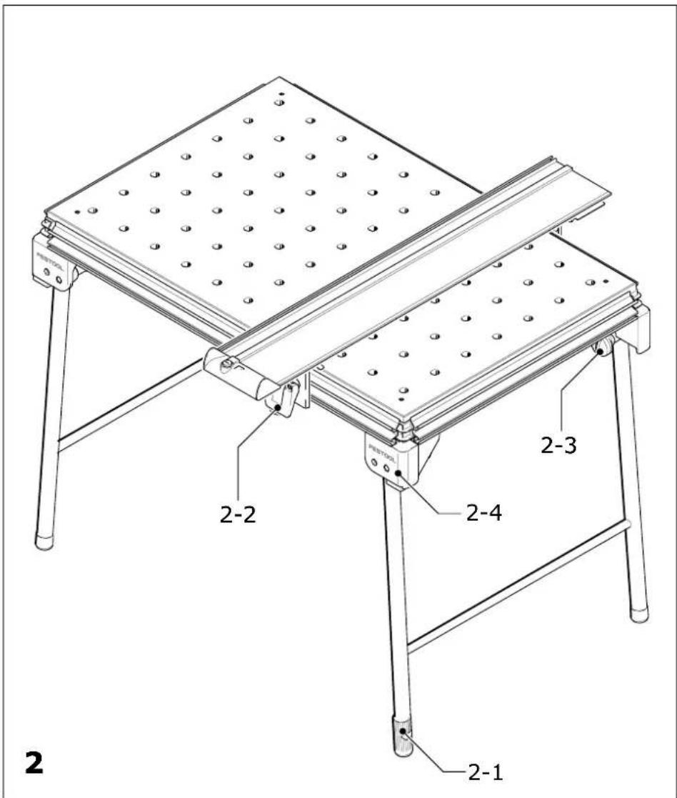
text_image
2 2-1 2-2 2-3 2-4 PENTOOL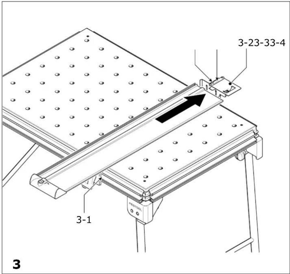
text_image
3-23-33-4 3-1 PESTOOL 3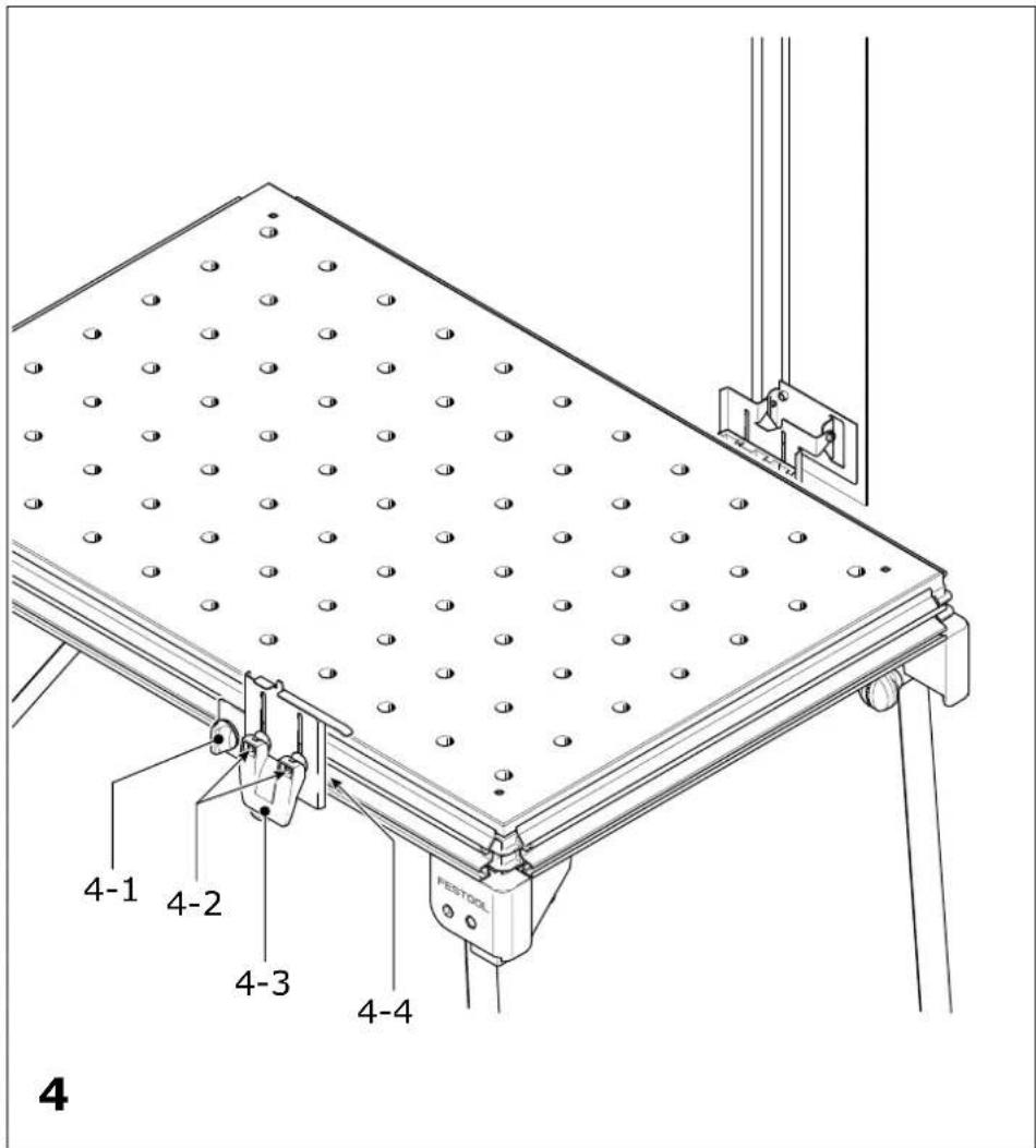
text_image
4-1 4-2 4-3 4-4 FESTOOL 4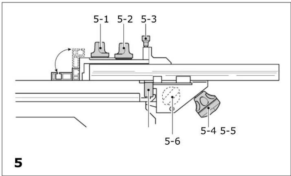
text_image
5-1 5-2 5-3 5-6 5-4 5-5 5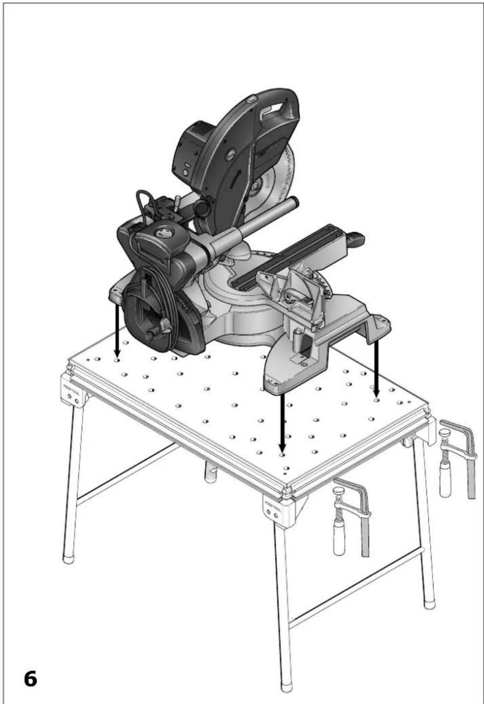
natural_image
Technical illustration of a mechanical cutting machine on a workbench, showing mounting hardware and mounting holes (no text or symbols present)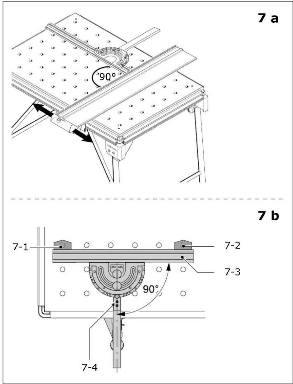
1 Technische Daten
MFT/3 MFT/KAPEX
| Bench dimensions (width x length) 1157 x 773 mm 869 x 581 mm | |
| Bench height - with foldaway legs 900 mm 790 mm | |
| - without foldaway legs 180 mm 180 mm | |
| max. working width 700 mm - | |
| max. workpiece thickness 78 mm - | |
| Weight 28 kg 18 kg | |
2 Symbols

Warning of general danger

Read the Operating Instructions/Notes!
The specified illustrations are at the beginning of the Operating Instructions.
3 Scope of delivery
[1-1] Bench consisting of: profile frame, corner feet, perforated top, foldaway legs MFT/3 only
[1-2] Support unit
[1-3] Guide rail FS 1080
[1-4] Swivel unit
[1-5] Pre-set profile setting rail and
[1-6] Stop ruler
[1-7] Additional clamp for stop ruler
[1-8] Stop flag MFT/3-AR
[1-9] Deflector
4 Intended use
The multifunction table MFT/3 is designed for safe, accurate sawing and routing in combination with Festool electric power tools.
The clamping systems included in the accessories programme enable the user to attach workpieces securely to the worktop. The base becomes a work bench for various tasks such as planing, sanding, carving, etc.
The multifunction table MFT/KAPEX was specially designed for attaching the KAPEX KS 120/KS 88.
The user bears the responsibility for damage and accidents caused by improper use.
5 Setting up and attaching
Accessory attachments can be secured at different points on the multifunction table to enable different working positions.
In the standard working position, the user stands along one side of the bench [Fig. 2]. In these operating instructions, this side of the bench is referred to as the "front".
5.1 Setting up
Screw on the knobs [2-3] until the stop is reached. Unfold the foldaway legs and tighten the knobs on the joints to secure. Turn the end cap [2-1] on the right to adjust the length of the leg and compensate for an uneven floor surface.
The corner feet [2-4] are fitted with rubber caps so that the bench stands securely when the legs are folded away.
5.2 Attaching the guide rail
Stops [3-1/4-4] are attached to the longitudinal profile on the front and back of the bench ex works for the recommended working position.
The swivel unit [1-4/3-2] is secured to the longitudinal back edge and the support unit [1-2/2-2] to the longitudinal front edge.
Unscrew the height adjustment clamp [4-3] and the rotary knob [4-1], slide the units along the profiled groove from the left up to the stop and then tighten the rotary knob [4-1] again to secure. To eliminate play, you can adjust both units in the profiled groove by turning the adjusting screws [4-2] in the guide spring using a size 2.5 Allen key.
To make both units more accessible, lift the metal plates all the way up and push down the clamping lever [4-3] to secure in position. If required, you can adjust the screws [4-2] to increase the clamping effect.
To attach the guide rail, place on the key [3-3] and make sure that the end of the rail is resting on the support plate and the key is located correctly in the groove.
Secure the guide rail in this position with the two screws [3-4] and tighten using the hexagon wrench.
5.3 Defl ector
The defl ector [1-9] prevents the extraction hose and the power cable from catching on the guide rail. The defl ector is attached to the end of the guide rail and secured with the rotary knob [1-10].
5.4 Attaching the pre-set profi le setting rail
The rail can be attached at any point along the clamping edge of the bench and is so versatile, it can be used as a cross stop or a longitudinal stop.
Before attaching, make sure that the V groove on the fence is not dirty.
▶ Open the clamping jaws using the knob [5-4].
▶ Place the fence with guide rail [5-5] onto the clamp rail from above.
▶ Secure the clamp segment using the knob [5-4]
The additional clamp [1-7] is designed to secure the stop ruler.
▶Guide the additional clamp into the V groove on the MFT/3 and the guide slot on the stop ruler.
- Secure the additional clamp using the clamp lever and the rotary knob.
5.5 Mounting the KAPEX
The perforated top on the MFT/KAPEX was specially designed for mounting the KAPEX KS 120/KS 88.
▶Mount the machine on the MFT/KAPEX as shown in Fig.[6].
▶ Secure the machine to the MFT using clamps.

WARNING
Risk of injury
▶Before starting work, make sure that the machine is secured properly
▶Respect the maximum workpiece dimensions.
6 Working with the MFT
6.1 Adjusting the pre-set profi le setting rail
Check the angle setting of the pre-set profi le setting rail before starting work. Align the guide rail fi rst of all [7a].
▶Align the guide rail at right angles to the pre-set profi le setting rail.
▶If an angle of 90^ is not possible, slide a support unit on the guide rail until the angle is correct.
▶Secure the guide rail.
① Slide the relevant stop [3-1/4-4] along the table profile to retain the setting permanently.
If required, the pre-set profi le setting rail can also be aligned in relation to the perforated top provided the necessary clamps (accessories) are available.
▶Insert the clamps [7-1] and [7-2] as shown in Fig. [7b] and move the stop ruler [7-3] to a 90° position.
If the stop ruler does not rest evenly against the clamps:
▶Loosen the screws [7-4] and the rotary knob €[5-2]. The retaining pin must be engaged in the 90° notch.
▶Set the angle at 90^ in relation to the clamps and tighten the screws.
The fence can be adjusted in the following ways:
Adjustment parallel to the bench edge:
▶ Loosen the rotary knob [5-4].
▶Slide the stop into the groove on the MFT/3.
Adjustment at right angles to the bench edge:
▶ Loosen the rotary knob [5-4].
▶Slide the stop into the groove on the MFT/3.
Adjusting the stop ruler [5-6] lengthways
▶Loosen the rotary knob [5-1]. The stop ruler can be moved to a lower position for thin workpieces or a higher position for thicker workpieces.
Angle adjustment using the scale
▶ Loosen the rotary knob [5-2] and lift the retaining pin [5-3]. The rotary retaining pin engages in the most common angle positions.

WARNING
Risk of injury
▶ Always use the fence in a fixed position and do not use to slide the workpiece along!
▶ Make sure that all rotary knobs on the fence are tightened before starting work.
Stop fl ag
The adjustable stop MFT/3-AR [1-8] is used to adjust the distance to the tool and the length of the workpiece section being processed.
6.2 Adjusting the guide rail in relation to the workpiece
▶ Before sawing or routing, lower the guide rail and support unit [1-2] until the guide rail rests flat at on the workpiece.
Caution: the nose of the support unit must be seated in the groove on the underside of the guide rail without play.
▶ Clamp the swivel unit [1-4] and the support unit [1-2] using the clamping levers.
▶ Clamp the workpiece securely to the MFT/3 using MFT clamps (accessories) or an FSZ clamp (accessories).
For safe machining of narrow and/or short workpieces:
▶ Place a piece of material of the same thickness under the guide rail.
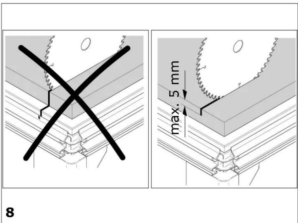
6.3 Adjusting the cutting depth for sawing [Fig. 8]
Always make sure that the cutting depth setting is correct in relation to the workpiece thickness. We recommend setting a cutting depth to a maximum of 5 mm more than the workpiece thickness to protect the profile frame from damage.
6.4 Turning the perforated top
When worn on one side, the perforated top can be turned over. Loosen the four screws in the corners underneath the bench.
7 Accessories
The order numbers of the accessories and tools can be found in the Festool catalogue or on the Internet under "www.festool.com".
8 Customer service and repair

Only through manufacturer or service workshops: Please find the nearest address at: www.festool.com/Service

Use only original Festool spare parts! Order No. at: www.festool.com/Service
Information on REACH:
www.festool.com/reach