
GWM100ME - Gas detector ABUS - Free user manual and instructions
Find the device manual for free GWM100ME ABUS in PDF.
| Product type | Fixed gas detector for natural gas (methane) |
| Brand | ABUS |
| Model | GWM100ME |
| Dimensions (W x H x D) | 115 x 75 x 36.5 mm |
| Power supply | AC 220-240 V, 50/60 Hz |
| Power consumption | < 4 W |
| Sensor type | Semiconductor |
| Gas detected | Natural gas (methane) |
| Detection threshold | 6% LEL (Lower Explosive Limit) |
| Alarm sound level | ≥ 85 dB at 1 meter |
| Protection rating | IPX2D |
| Operating temperature range | -10 °C to +40 °C |
| Operating humidity | 0% to 95% |
| Device lifespan | 5 years (replacement date indicated on front) |
| Applied standard | EN 50194-1:2009 |
| Power cord length | Approx. 1.50 meters |
| Installation | Wall-mounted, approx. 30 cm from ceiling (gas lighter than air) |
| Main functions | Methane leak detection, audible and visual alarm (LED), Test/Reset button, self-test on power-up |
| Maintenance and cleaning | Monthly test recommended, exterior cleaning with soft dry cloth, no chemicals |
| Safety | Do not cover, paint or open the device; installation by qualified person; replacement after 5 years |
| Package contents | Gas detector, wall bracket, connection cable, mounting hardware, user manual |
Frequently Asked Questions - GWM100ME ABUS
User questions about GWM100ME ABUS
0 question about this device. Answer the ones you know or ask your own.
Ask a new question about this device
Download the instructions for your Gas detector in PDF format for free! Find your manual GWM100ME - ABUS and take your electronic device back in hand. On this page are published all the documents necessary for the use of your device. GWM100ME by ABUS.
USER MANUAL GWM100ME ABUS
natural_image
White electronic device with ventilation slots and ports, no visible text or symbols on body
text_image
ABUSSecurity Tech Germany
Bedienungsanleitung
Gaswarnmelder
User manual
Gas alarm
natural_image
Simple line drawing of a heart shape with a small S inside, no text or symbols present.CE
EN 50194-1:2009
GB Please read this guide carefully before installation and use. Keep these instructions and provide all users with instruction on how to use it.
Page 14 - 25
text_image
Technical diagram of a device with numbered parts and exploded view, showing internal components and wiring connections.© ABUS | D 58292 Wetter (Germany)
www.abus.com
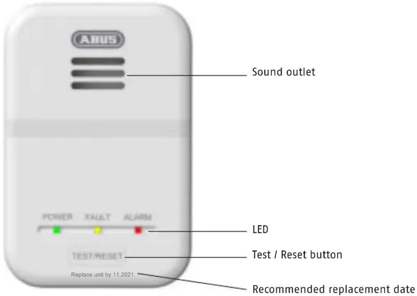
Device description
text_image
ABUS Sound outlet POWER FAULT ALARM LED Test / Reset button TEST/RESET Replace unit by 11.2021 Recommended replacement dateSpecifications
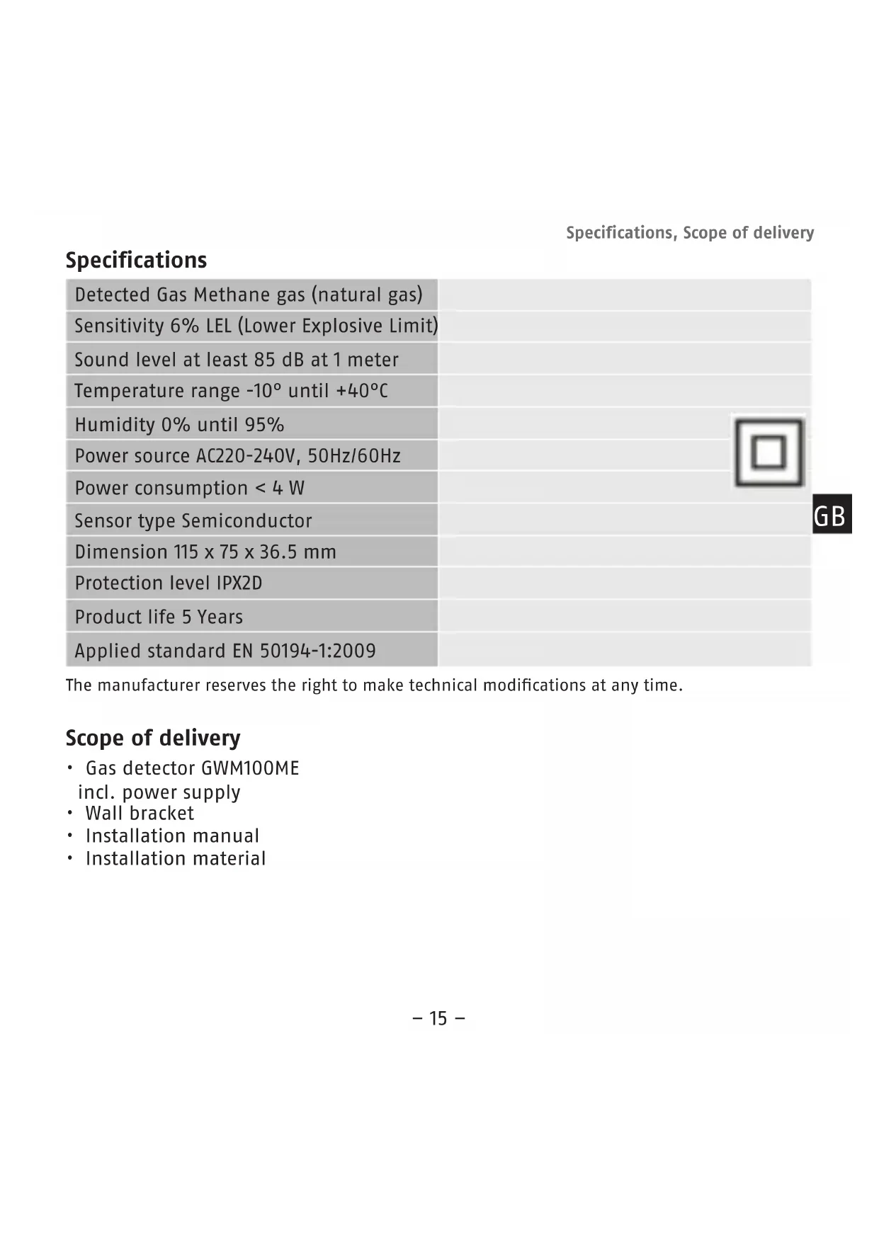
| Detected Gas Methane gas (natural gas) | |
| Sensitivity 6% LEL (Lower Explosive Limit) | |
| Sound level at least 85 dB at 1 meter | |
| Temperature range -10° until +40°C | |
| Humidity 0% until 95% | |
| Power source AC220-240V, 50Hz/60Hz | |
| Power consumption < 4 W | |
| Sensor type Semiconductor | |
| Dimension 115 x 75 x 36.5 mm | |
| Protection level IPX2D | |
| Product life 5 Years | |
| Applied standard EN 50194-1:2009 |
GB
The manufacturer reserves the right to make technical modifications at any time.
Scope of delivery
• Gas detector GWM100ME incl. power supply
- Wall bracket
• Installation manual
- Installation material
Explanation of symbols
The following symbols are used in this manual:
| Symbol | Signal word | Meaning |
 | Warning | Indicates risk of injury or health hazards. |
 | Warning | Indicates risk of injury or health hazards caused by electrical voltage. |
 | Important Indicates possible damage to the device/accessories. | |
 | Note Indicates important information. | |
Warning
- This gas alarm detects methane (natural gas). Other gases, steam, heat, smoke and glow of fire/flames were not detected! Detectors with special sensors are required for this!
• The danger with gases is that they mix in with the air and are, as a result, highly flammable and the smallest of sparks could cause an explosion!
- In the daily handling of the gas alarm, it must be borne in mind that it can not prevent an explosion, but only assumes a signaling in the event of a gas leakage. Please replace the gas alarm at least every 5 years in accordance with your own safety (see recommended replacement date on the front of the device).
- This alarm is equipped with a power plug for voltage of AC220-240V, 50Hz/60Hz. Please note that the gas alarm does not work in case of a
power failure!
- The gas installation as well as the switch-off device must comply with the valid national regulations according to EN 1775.
Proper use
Only use the device for the purpose which is was designed and built for. Any other use is considered inappropriate. This device may only be used for the following purpose(s):
• Detecting methane gas (natural gas) in private households
Warning
Observe the following instructions to prevent any failure of the device:
- Do not cover the device!
- Do not paint over the device or cover it with wallpaper!
- Never open the device or attempt to repair it, as its function can then no longer be guaranteed.
Failure to observe this instruction will invalidate the warranty!
- Do not use the device if it has been dropped or damaged in any other way.
- If you pass on the device to someone else, you must include this user manual.
Warning
- Danger of electric shock by unauthorized opening, altering or manipulating the device!
- Danger of electric shock by unauthorized immersion of the device in water!
Before mounting:
This gas alarm must be installed by a competent person!
Warning
- Keep children away from the packaging - there is a risk of suffocation!
- Remove all packaging material before using the device.

Note
Determination of the installation location
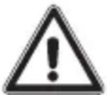
Natural gas is lighter than air, so the gas will tend to rise and fill all the volume above the level of escape. The gas alarm should be installed above the level of a possible gas escape and near the ceiling, about 30 cm from the ceiling. For sloping ceilings, the gas alarm should be installed with a distance of approx. 50 cm from the roof ridge.
The gas alarm should not be installed
• In any outside location.
- In an area where the temperature may drop below 0^ or exceed 40^ .
- Directly above cooking appliances (Minimum distance of approx. 1 meter) or adjacent to an extractor fan.
- Directly above a sink.
- Next to a door or window.
• In an enclosed space, e.g. behind a curtain or in furniture, e.g. cupboards
• In a damp or humid location or where dirt and dust may block the sensor.
Recommendend installation locations
- The gas alarm should be installed in the room where a gas escape is most likely to occur. This may be the kitchen because of the presence of a gas cooker and other appliances.
- Natural gas is lighter than air, so the gas will tend to rise and fill all the volume above the level of the escape. The gas alarm should be installed on the wall above the level of a possible gas escape and near the ceiling (about 30 cm from the ceiling), in a place where air movement are not impeded by furniture and furnishings.
• Make sure you have a socket that can be reached with the connection cable, length approx. 1,50 meters (do not use extension cables!). - The TEST / RESET button should be easily reached.
• The alarm signal must be easily heard in case of gas leakage. - Avoid spraying air fresheners, hair spray, or other aerosols near the gas alarm!
text_image
Gas alarm 150 cm 30 cmInstallation:
Warning
- When marking out the drill holes, make sure there are no electrical or cables, pipes or other important components behind them!
If possible, work with a locating device (cable detector)!
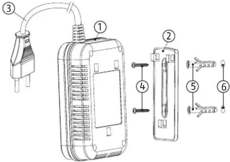
Mounting steps
- Disconnect the bracket (2) from the alarm body (1).
- Hold the bracket at the mounting location on the wall and mark the two drill holes (6).
- Drill two ø 5 mm holes in the wall, then insert the plastic plugs (5) into the holes.
- Attach the bracket to the plastic plugs and fix tightly the screws (4) into the plugs.
- Fit the gas alarm on the bracket and pull it down until matching well on the bracket.
- Insert the power plug (3) into the socket.
text_image
Technical diagram of a medical or electrical device with numbered parts and exploded view, likely illustrating a procedure or assembly.- A confirmation tone sounds and the "Power"-LED is flashing for about 3 minutes (Preheat).
- When the "Power"-LED is constant on, the gas alarm is ready for use.
Status summary table:
| Status Illustration | Green LED Yellow | LED Red LED | Horn | ||
| Self-test Power on 0n 0n 0n 1x chirp | |||||
| Preheat Ca. 3 minutes | Flashes No No | - | |||
| Standby Normal condition Shines | No No - | ||||
| Test | Press "Test" key | Shines | No | Flashes | 1x chirp |
| ALARM | Gas detected | Shines | No | Flashes | Alarm |
| Silence | Press "Test" key when Alarm | Shines | No Flashes | - | |
| Sensor fault | The detector must be replaced | Shines | Shines | No 1x chirp once per 30 sec. | |
| End of life The detector must be replaced | Shines | Shines | No 3x chirp per 30 seconds | ||
| Power off | Power wire is unplugged, power failure | No No No - | |||
GB
Emergency actions
If the gas detector initiates an alarm signal or there is a smell of gas, keep calm and carry out the following actions:
- Extinguish all naked flames, including all smoking material, e.g. candles, cigarettes.
- Turn off all gas appliances, e.g. gas heater, gas cooker.
- Do not switch on or off any electrical equipment, including the gas detector.
- Turn off the gas supply at the gas main control.
- Open doors and windows to increase ventilation.
- Leave the building, warn your fellow residents and make sure they also leave.
- Do not use a telephone in the building where gas may be present.
- Call the fire brigade from outside the building - Emergency call: 112.
- Do not re-enter the building until you have ensured that there is no more gas present.
If the gas alarm continues to operate, even after an alarm resetting action, where appropriate, and the cause of the leak is not apparent and/or cannot be corrected, vacate the premises and notify the gas supplier in order that the installation may be tested and made safe.
Preventive measures
Inform every person in your household about the dangers of gas and the triggering of a gas alarm. Make sure that in case of alarm each person knows what to do. Create an emergency evacuation plan from each room / floor to a designated meeting point outside the house. Practice at least once a year the alarm with your family and improve your escape routes and explanations if problems occur.
Maintenance, testing and care
The green "Power" LED must always be on. The LED shows you that the gas alarm is turned on and everything is working properly. If the green LED is not on, first check if the plug is still in or the socket is still live. If this does not seem to be the problem, the detector is likely to have an internal defect and must be exchanged.
Verify the unit's sound and LED light by pushing the "Test" button once a month. The gas alarm is maintenance-free.
- Only clean the detector with a soft, dry cloth. Do not use any detergents containing alcohol, acid, gasoline, chemicals or other similar products. These agents attack the surface of the device and damage it.
- Do not allow water to penetrate inside the device!
- Do not clean the device in a dishwasher!
Warranty:
- ABUS products are designed and manufactured with the greatest care and tested according to the applicable regulations.
- The warranty only covers defects caused by material or manufacturing errors. If there are demonstrable material or manufacturing errors, the product will be repaired or replaced at the manufacturer's discretion.
- In such cases, the warranty ends when the original warranty period expires. All further claims are expressly rejected.
- ABUS will not be held liable for defects and damage caused by external influences (e.g. transport, use of force, operating errors), inappropriate use, normal wear and tear or failure to observe the instructions in this manual.
- In the event of a warranty claim, the original receipt with the date of purchase and a short description of the problem must be supplied along with the product.
- If you discover a defect on your product which existed at the time of purchase, contact your dealer directly within the first two years.
Declaration of conformity
ABUS August Bremicker Söhne KG, Altenhofer Weg 25, 58300 Wetter, hereby declares that the device GWM100ME complies with the basic requirements and other relevant terms of the 2004/108/EG. For further information on the CE declaration or view the CE declaration, please get in touch with ABUS August Bremicker Söhne KG, Kunden-servicecenter, Altenhofer Weg 25, 58300 Wetter.
Information on the EU directive on waste electrical and electronic equipment
To protect the environment, do not dispose of the device with domestic refuse at the end of its service life. It can be disposed of at one of the appropriate collection points in your country. Please obey your local regulations when disposing of material.
natural_image
Simple line drawing of a trash bin with two crossed lines and a horizontal bar below (no text or symbols)Dispose of the device in accordance with EU directive 2002/96/EC – WEEE (Waste Electrical and Electronic Equipment). If you have any questions, please contact the department of your local authority which is responsible for waste disposal. Used equipment can be disposed of, for example, by your local or municipal authority, the local waste disposal company or your dealer.
GB Subject to technical alterations.
No liability for mistakes and printing errors.
© ABUS | D 58292 Wetter (Germany)
www.abus.com
text_image
Technical diagram of a device with numbered parts and exploded view, showing internal components and wiring connections.© ABUS | D 58292 Wetter (Germany)
www.abus.com
text_image
Technical diagram of a device with numbered parts and exploded view, showing internal components and assembly steps.© ABUS | D 58292 Wetter (Germany)
www.abus.com
text_image
Technical diagram of a device with numbered parts and exploded view, showing internal components and assembly steps.© ABUS | D 58292 Wetter (Germany)
www.abus.com