
FUMK50000W - Security System ABUS - Free user manual and instructions
Find the device manual for free FUMK50000W ABUS in PDF.


| Product type | Security system |
| Brand | ABUS |
| Model | FUMK50000W |
| Dimensions (L x W x H) | 120 x 80 x 30 mm |
| Weight | 200 g |
| Power supply | 3V CR123A batteries or 5V USB power adapter |
| Battery life | Up to 2 years under normal use |
| Connectivity | Wi-Fi 2.4 GHz, Bluetooth 4.2 |
| Detection range | Up to 10 meters (120° angle) |
| Built-in siren | Yes, 85 dB |
| Notifications | Push notifications on smartphone via ABUS app |
| Compatibility | iOS and Android |
| Encryption | AES 128-bit |
| Operating temperature | -10°C to 50°C |
| Max humidity | 95% non-condensing |
| Maintenance and cleaning | Clean with a soft, dry cloth. Do not use chemical products. |
| Security | Tamper protection (anti-sabotage) |
| Spare parts and repairability | Replaceable battery, spare parts available at abus.com |
| Warranty | 2 years |
| Box contents | 1 sensor, 1 wall mount, 2 batteries, 1 USB adapter, 1 manual |
Frequently Asked Questions - FUMK50000W ABUS
User questions about FUMK50000W ABUS
0 question about this device. Answer the ones you know or ask your own.
Ask a new question about this device
Download the instructions for your Security System in PDF format for free! Find your manual FUMK50000W - ABUS and take your electronic device back in hand. On this page are published all the documents necessary for the use of your device. FUMK50000W by ABUS.
USER MANUAL FUMK50000W ABUS
natural_image
Line drawing of a door and adjacent rectangular object (no text or symbols)Installation instructions and user manual
Konfiguration/ Configuration/ Configuration/
Configuratie/ Configuration/ Configurazione
Vorwort
natural_image
Simple line drawing of a door and cabinet (no text or symbols)
Montage
natural_image
Simple 3D illustration of a rectangular block with upward and downward arrows indicating direction (no text or symbols)
natural_image
Isometric diagram of a rectangular electronic component with a separate 3D coordinate system (X, Y, Z axes) shown in the corner, no text or symbols present.| Oberfläche |   | |
| Fe | X 14mm Y 20mm Z 28mm | 12mm 15mm 23mm |
| Fe | X 10mm Y 8mm Z 13mm | 5mm 7mm 10mm |
Many thanks for your purchase of this wireless opening detector. This device is built according to state-of-the-art technology. It complies with current domestic and European regulations.
Hereby, ABUS Security-Center GmbH & Co. KG declares that the radio equipment type FUMK50000W/B, FUMK50010W/B is in compliance with Directive 2014/53/EU. The full text of the EU declaration of conformity is available at the following internet address: www.abus.com >> Search >> FUMK50000W/B,
FUMK50010W/B >> Downloads
The Declaration of Conformity can also be obtained from the following address:
Pay attention to the notes and instructions in these operating instructions! If you do not follow these instructions, your guarantee claim becomes invalid! No liability can be accepted for resulting damages! The product may not be changed or modified in any way.
Battery Warning

The device is supplied with direct current from a 3 V lithium battery. To guarantee a long working life and avoid fire and injury, please note the following:
- Do not dispose of the battery in domestic waste.
- Do not expose the battery to direct sunlight or sources of heat.
- Do not store the battery under high temperatures.
- The battery must not be burned.
- The battery must not come into contact with water.
- The battery must not be dismantled, pierced or otherwise damaged.
-
The battery contacts must not be short-circuited.
-
The battery must be kept away from small children.
- The battery cannot be recharged.

Im- portant
Check for correct polarity!
Insert the battery into the wireless opening detector.
1. Scope of delivery
1 x installation instructions
1 x magnet
1 x CR2 3 V lithium battery
1 x magnet holder
1 x opening detector
2 x countersunk screws (magnet holder)
2 x rounded head screws (detector)
4 x magnet spacers
2 x detector spacers
4 x jumpers (FUMK50000W/B)
2 x jumpers (FUMK50010W/B)
2. Technical data
| Power supply | 3V CR2 Li/MnO2 |
| Power consumption/energy consumption | standby current :5 μA (FUMK50000), 9 μA (FUMK50010) 28 mA max. |
| Battery life | Typically >2 years |
| Operating voltage | 3 V DC |
| Power consumption | 0.03 A |
| Battery under voltage threshold | 2.2 V, ‘Flat battery’ fault at < 2.4 V |
| Frequency: | 868.6625 MHz / F |
| Weight | ca. 76g |
| Dimensions (WxHxD in mm) | 33x89x29 |
| Battery life | Up to 36 months |
| Environment class | II (-10 to +55 °C) |
| Security level | 2 |
| INCERT no. | C-019-0430 |
| Housing material | ABS |
| Wireless transmission power | Max. 10mW |
| Normen | EN 50131-2-6 |
3. Implementation

Attaching the detector:
- Do not attach on or near metal surfaces!
- Do not attach within 1 metre of gas, water or power lines!
- Do not attach near electronic devices (e.g. computers, photocopiers or other detectors)!
Select an installation location which is within the wireless range of the alarm panel or repeater.
Range
The range is dependent on the surrounding conditions.
The signal strength should not fall below 4. Testing using the Secvest: Installer menu → Test → Detector signal
Installation location
The best place to install the wireless opening detector is the upper corner of the window/door frame. Ensure that the detector is installed on a flat surface so the removal wall contact switches correctly

natural_image
Simple line drawing of a door and cabinet (no text or symbols)
Installation

natural_image
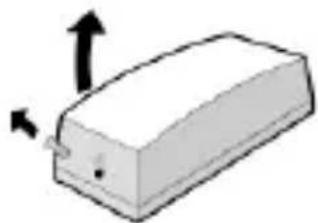
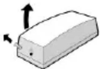
Simple 3D illustration of a rectangular block with upward and downward arrows indicating direction (no text or symbols)- Open the housing by loosening the screw and then removing the cover.
- Remove the PCB from the housing. Loosen the screw and lift out the PCB.


- Fasten the detector and magnet holder centrally to the "3" marking with a maximum spacing of 10 mm.
- Use the base plate of the detector and the magnet holder to mark the fastening holes 1, 4, 6 and 7.
- Use the rounded head screw for the detector and the countersunk screw for the magnet holder.
- Ensure that the anti-removal wall contact “2” can be moved inwards..
- Cable opening “5” for external detectors with a connection cable of max. 10 metres
Approximation and separation distances on ferromagnetic and non-ferromagnetic mounting sur-faces due to EN 50131-2-6, chapter 5.2 c

natural_image
Isometric line drawing of a rectangular electronic component with mounting base, accompanied by a 3D coordinate system (X, Y, Z axes) shown in the legend.| Interface |  |  |
| Fe | X 14mm | 12mm |
| Y 20mm | 15mm | |
| Z 28mm | 23mm | |
| Fe | X 10mm | 5mm |
| Y 8mm | 7mm | |
| Z 13mm | 10mm |
4. Training the detector (Zone 1)
Ensure that the Secvest (receiver) is in learning mode. Keep the anti-removal wall contact pressed. When deinstalled, also keep the cover contact pressed. Open one of these contacts until successful reception is confirmed (double tone).
Using a wireless extension (wireless accessory module), hold the signal LED of the detector at a maximum of 50 mm above the IR receiver. Train the zones as described below.

The possible configurations of the individual zones can be found on the previous pages. You can also use this wireless magnet contact as a wireless module.
FUMK50000W/B
5. Device description

1 Fixing screw
2 Jumper connection LK4
Jumper connection LK2
3 Magnet switch
4 Jumper connection LK3
Jumper connection LK1
5 Battery
6 Screw clamp block
7 Tamper protection, cover
8 LED
| LK1LK3 | Operation mode of external contacts |  | ||
| LK2 | Internal Contact | |||
| LK4 | Programmierung |
6. Signal LED
| Operating status | Signal |
| Operation mode | No signal |
| Transmit / program mode IR | 4 x flashing |
| Program mode detector intern | flashing |
Activating the LED
Attach a jumper to contacts LK1 and LK3. Short-circuit the LK4 contact with a jumper until the LED flashes continuously. Remove this again. The LED is now activated. Restore the original position of the jumper.
Deactivating the LED
Attach a jumper to contact LK1. Short-circuit the LK4 contact with a jumper until the LED flashes continuously. Remove this again. The LED is now deactivated. Restore the original position of the jumper.
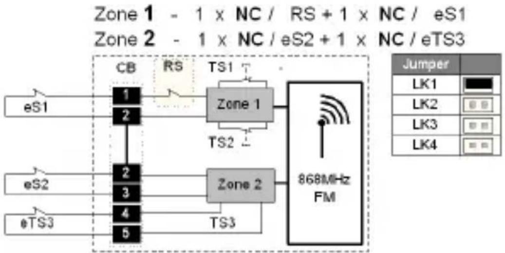
7. Connecting wired detectors Connection of an external contact (zone 1)
Only one NC contact can be connected to terminals 1 and 2 (Reed). The evaluation takes place via the opening detector itself.
Connection of external contacts (Zone 2)
You can connect more than one external detector with NC contacts (or NO contacts) to this opening detector. Two or more devices must be serially (parallel) connected. The cable resistance must not exceed 100 ohm.
Connect the alarm line of the wired detector to „ALARM“ (screw clamp 2 and 3) and the tamper line of the wired detector to „TAMP“ (screw clamp 4 and 5).
Training of external contacts (Zone 2)
The external contacts of the opening detector are trained for an extra zone of the system Open and close the “TAMP” connection until successful reception is confirmed.

Using the detector only as radio modules
You can also use this radio magnet contact as a radio module.
- Close the jumper connection LK2 to deactivate the internal magnet contact.
- Connect the detectors to the reed contacts and remove the existing wire strap (zone 1).
- Connect the detector as external zone (see above) (zone2).
FUMK50010W/B
8. Device description

1 Fixing screw
2 Jumper connection LK2
3 Magnet switch
4 Jumper connection LK3
5 Battery
6 Screw clamp block
7 Tamper protection, cover
8 LED
2k2
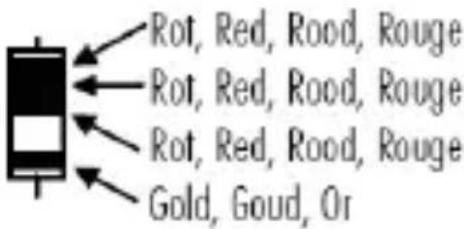

flowchart
graph TD
    A["2k2"] --> B["4k7"]
    B --> C["Alarm"]
    B --> D["Tamper"]
    E["ALARM"] --> F["ALARM"]
4k7

| LK2 | Internal Contact |  Off Off | |
 On On | |||
| LK3 | LED |  On On | |
 Off Off |
9. Signal LED
| Operating status | Signal |
| Operation mode | No signal |
| Transmit / program mode IR | 4 x flashing |
| Program mode detector intern | flashing |
Activating/deactivating LEDs
Connect the jumper to contact LK3 to activate the LED. Remove the jumper to deactivate it.
10. External Contacts
Connecting external contacts
External contacts can be connected via DEOL to this opening detector. Two or more devices must be connected in series. The cable resistance must not exceed 100 ohm. Connect the external devices to the screw clamps on the PCB. Pay attention to the resistance values.
Training external contacts
The external contacts of the wireless opening detector are trained for an extra zone of the system:
- Switch your wireless centre to learn mode. Observe the system instructions.
- Connect both screw clamps on the screw clamp block with a 2K2 resistor.

flowchart
graph TD
    A["4k7"] --> B["2k2"]
    B --> C["Tamper"]
    D["Alarm"] --> A
    E["ALARM"] --> A
- Remove the resistor to trigger wireless transmission. OR:
Connect the external contact to a detector and open the tamper protection.
- Check that the alarm centre has recognised the detector.
Using detectors as wireless modules
- This wireless magnet contact can also be used as a wireless module.
- Close the jumper connection LK2 to deactivate the internal magnet contact.
- Connect the external detectors to the clamps of the screw clamp block and train them (see “Connecting external contacts” and “Training external contacts”).
Préface
Chère cliente, cher client,
natural_image
Simple line drawing of a door and cabinet (no text or symbols)
Montage

natural_image
Simple 3D illustration of a rectangular block with two arrows indicating upward and downward motion (no text or symbols)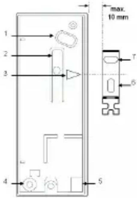
natural_image
Isometric line drawing of a rectangular electronic component with mounting base, accompanied by a 3D coordinate system (X, Y, Z axes) shown in the legend.| Surface |  |  |
| Fe | X 14mm | 12mm |
| Y 20mm | 15mm | |
| Z 28mm | 23mm | |
| Fe | X 10mm | 5mm |
| Y 8mm | 7mm | |
| Z 13mm | 10mm |
4. Apprentissage du detector (Zone 1)
natural_image
Simple line drawing of a door and cabinet (no text or symbols)
Montage

natural_image
Simple 3D illustration of a rectangular block with upward and downward arrows indicating direction (no text or symbols)
natural_image
Isometric line drawing of a rectangular electronic component with mounting base, accompanied by 3D coordinate axes (X, Y, Z) shown in the legend.| Oppervlak |  |  |
| Fe | X 14mm | 12mm |
| Y 20mm | 15mm | |
| Z 28mm | 23mm | |
| Fe | X 10mm | 5mm |
| Y 8mm | 7mm | |
| Z 13mm | 10mm |
Linker Kreuthweg 5, 86444 Affing, Germany

Vigtigt
natural_image
Simple line drawing of a door and cabinet (no text or symbols)
Montage
natural_image
Simple 3D diagram of a rectangular block with upward and downward arrows indicating direction (no text or symbols)
- Fastgør melderen og magnet- holderen i midten til at markere "3" med maks.10 mm afstand.
natural_image
Isometric line drawing of a rectangular electronic component with mounting base, accompanied by a 3D coordinate system (X, Y, Z axes) shown in the legend.| Overflade |  |  |
| Fe | X 14mm | 12mm |
| Y 20mm | 15mm | |
| Z 28mm | 23mm | |
| Fe | X 10mm 5mmY 8mm 7mmZ 13mm 10mm |
natural_image
Simple line drawing of a door and cabinet (no text or symbols)
Montaggio

natural_image
Simple 3D illustration of a rectangular block with upward and downward arrows indicating direction (no text or symbols)
natural_image
Isometric line drawing of a rectangular electronic component with mounting base, accompanied by a 3D coordinate system (X, Y, Z axes) shown in the legend.| Superficie |  |  |
| Fe | X 14mm | 12mm |
| Y 20mm | 15mm | |
| Z 28mm | 23mm | |
| Fe | X 10mm | 5mm |
| Y 8mm | 7mm | |
| Z 13mm | 10mm |
flowchart
graph TD
    A["øS1"] --> B["CB"]
    B --> C["RS"]
    C --> D["Zone 1"]
    D --> E["868MHz FM"]
    F["Zone 2"] --> G["TS1"]
    G --> H["TS2"]
    H --> I["TS3"]
    I --> J["Red X"]
    style J stroke:#ff0000,stroke-width:2px
| Jumper | |
| LK1 | |
| LK2 | |
| LK3 | |
| LK4 | |
Fig. 3
Zone 1 - 1 x NC / eS1
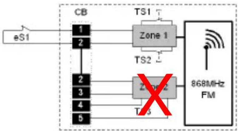
flowchart
graph LR
    eS1 --> CB
    CB --> Zone1["Zone 1"]
    CB --> Zone2["Zone 2"]
    Zone1 --> 868MHzFM["868MHz FM"]
    Zone2 --> 868MHzFM
    Zone1 --> TS1["TS1"]
    Zone2 --> TS2["TS2"]
    Zone1 --> TS3["TS3"]
    Zone2 --> TS4["TS4"]
    Zone1 --> TS5["TS5"]
    Zone2 --> TS6["TS6"]
    Zone1 --> TS7["TS7"]
    Zone2 --> TS8["TS8"]
    Zone1 --> TS9["TS9"]
    Zone2 --> TS10["TS10"]
    Zone10 --> 868MHzFM
| Jumper | |
| LK1 | |
| LK2 | |
| LK3 | |
| LK4 | |
Fig. 4

flowchart
graph TD
    A["CB"] --> B["1"]
    A --> C["2"]
    D["TS1"] --> E["Zone 1"]
    F["TS2"] --> G["Zone 2"]
    H["eS2"] --> I["3"]
    J["4"] --> K["5"]
    L["TS3"] --> M["868MHz FM"]
    N["X"] --> O["868MHz FM"]
    P["Jumper"] --> Q["LK1"]
    P --> R["LK2"]
    P --> S["LK3"]
    P --> T["LK4"]
Fig. 5

flowchart
graph TD
    A["eS2"] --> B["CB"]
    B --> C["1"]
    B --> D["2"]
    B --> E["2"]
    B --> F["3"]
    B --> G["4"]
    B --> H["5"]
    C --> I["TS1"]
    D --> J["TS2"]
    E --> K["Zone 2"]
    F --> L["TS3"]
    G --> M["868MHz FM"]
    I --> N["X"]
    J --> N
    K --> N
    L --> N
    M --> N
Fig. 6

flowchart
graph TD
    A["eTS3"] --> B["CB"]
    B --> C["1"]
    B --> D["2"]
    B --> E["3"]
    B --> F["4"]
    B --> G["5"]
    C --> H["Zone 1"]
    D --> I["Zone 2"]
    E --> J["TS3"]
    F --> K["TS3"]
    H --> L["TS1"]
    I --> M["TS2"]
    K --> N["868MHz FM"]
    style H stroke:#ff0000,stroke-width:2px
    style I stroke:#ff0000,stroke-width:2px
    style N stroke:#ff0000,stroke-width:2px
    style L stroke:#0000ff,stroke-width:2px
    style M stroke:#0000ff,stroke-width:2px
    style N stroke:#0000ff,stroke-width:2px
Fig. 7
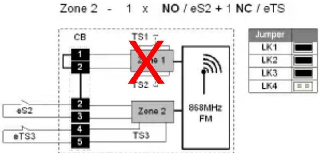
flowchart
graph TD
    A["CB"] --> B["1"]
    A --> C["2"]
    D["eS2"] --> E["2"]
    F["eTS3"] --> G["4"]
    H["TS1"] --> I["Zone 1"]
    J["TS2"] --> K["Zone 2"]
    L["TS3"] --> M["868MHz FM"]
    N["X"] --> O["Red X"]
    O --> P["868MHz FM"]
    Q["Jumper"] --> R["LK1"]
    Q --> S["LK2"]
    Q --> T["LK3"]
    Q --> U["LK4"]
Fig. 8
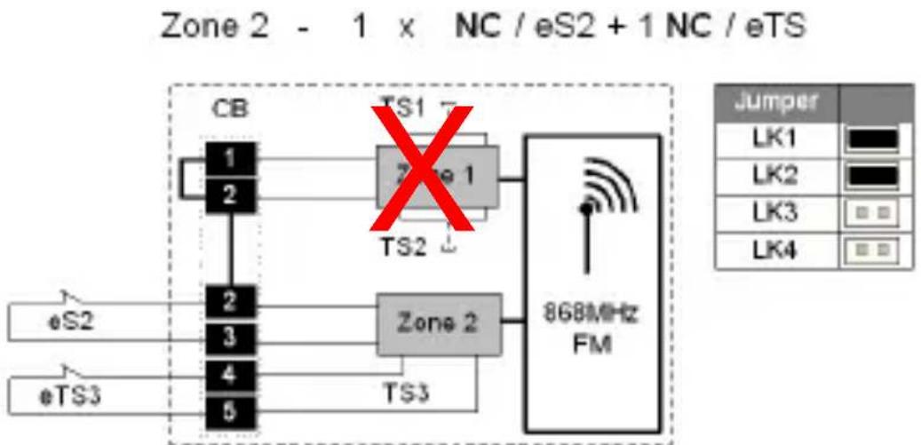
flowchart
graph TD
    A["CB"] --> B["Zone 1"]
    B --> C["868MHz FM"]
    D["0S2"] --> E["Zone 2"]
    F["0TS3"] --> G["Zone 2"]
    H["TS1"] --> I["TS2"]
    J["TS3"] --> K["TS2"]
    L["Jumper"] --> M["LK1"]
    L --> N["LK2"]
    L --> O["LK3"]
    L --> P["LK4"]
Fig. 9
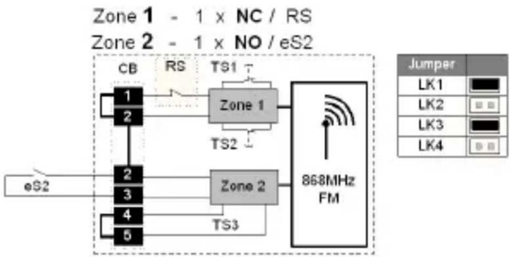
flowchart
graph TD
    subgraph Zone 1
        A["CB"] --> B["Zone 1"]
        C["1"] --> B
        D["2"] --> B
        E["2"] --> F["Zone 2"]
        G["3"] --> F
        H["4"] --> F
        I["5"] --> F
    end
    subgraph Zone 2
        J["TS1"] --> K["868MHz FM"]
        L["TS2"] --> K
        M["TS3"] --> K
    end
    N["eS2"] --> O["Ground"]
    P["Jumper"] --> Q["LK1"]
    P --> R["LK2"]
    P --> S["LK3"]
    P --> T["LK4"]
Fig. 10

flowchart
graph TD
    subgraph Zone 1
        A["CB"] --> B["1"]
        A --> C["2"]
        D["eS1"] --> E["2"]
        F["eS2"] --> G["3"]
        H["4"] --> I["5"]
    end
    subgraph Zone 2
        J["TS1"] --> K["Zone 1"]
        L["TS2"] --> M["Zone 2"]
        N["TS3"] --> O["868MHz FM"]
    end
    K --> O
    M --> O
    O --> P["Jumper"]
    style Zone 1 fill:#f9f,stroke:#333
    style Zone 2 fill:#ccf,stroke:#333
Fig. 11

flowchart
graph TD
    subgraph Zone 1
        A["1 x NC / RS + 1 x NC / eS1"] --> B["CB"]
        B --> C["2"]
        C --> D["2"]
        D --> E["3"]
        E --> F["4"]
        F --> G["5"]
    end
    subgraph Zone 2
        H["1 x NC / eS2 +"] --> I["868MHz FM"]
    end
    J["Jumper"]
    K["LK1"] --> L["Wireless Signal"]
    M["LK2"] --> N["Wireless Signal"]
    O["LK3"] --> P["Wireless Signal"]
    Q["LK4"] --> R["Wireless Signal"]
    I --> S["TS1 ↑"]
    I --> T["TS2 ↓"]
    I --> U["TS3 ↑"]
Fig. 12

flowchart
graph TD
    A["eS1"] --> B["CB"]
    C["eS2"] --> D["CB"]
    E["eTS3"] --> F["CB"]
    B --> G["RS"]
    D --> H["RS"]
    F --> I["TS1"]
    G --> J["Zone 1"]
    H --> K["Zone 1"]
    I --> L["TS2"]
    J --> M["868MHz FM"]
    K --> M
    L --> M
    M --> N["Jumper"]
    style A fill:#f9f,stroke:#333
    style C fill:#f9f,stroke:#333
    style E fill:#f9f,stroke:#333
    style B fill:#ccf,stroke:#333
    style D fill:#ccf,stroke:#333
    style F fill:#ccf,stroke:#333
    style G fill:#cfc,stroke:#333
    style H fill:#cfc,stroke:#333
    style I fill:#cfc,stroke:#333
    style J fill:#fcc,stroke:#333
    style K fill:#fcc,stroke:#333
    style L fill:#fcc,stroke:#333
    style M fill:#ffc,stroke:#333
Fig. 13
flowchart
graph TD
    subgraph Zone 1
        A["CB"] --> B["Zone 1"]
        C["RS"] --> B
        B --> D["868MHz FM"]
    end
    subgraph Zone 2
        E["TS1"] --> D
        F["TS2"] --> D
        G["TS3"] --> D
    end
    subgraph eS1
        H["eS1"] --> I["1"]
        J["eS2"] --> K["2"]
        L["eTS3"] --> M["3"]
        N["eTS3"] --> O["4"]
        P["eTS3"] --> Q["5"]
    end
    subgraph eS2
        R["eS2"] --> S["2"]
        T["eS2"] --> U["3"]
        V["eTS3"] --> W["4"]
        X["eTS3"] --> Y["5"]
    end
    subgraph eS2 + eS2 + eTS3
        Z["JK1"] --> AA["868MHz FM"]
        AB["JK2"] --> AC["868MHz FM"]
        AD["JK3"] --> AE["868MHz FM"]
        AF["JK4"] --> AG["868MHz FM"]
    end


- Vorwort
- Montage
- Battery Warning
- Scope of delivery
- Technical data
- Implementation
- Range
- Installation location
- Installation
- Training the detector (Zone 1)
- FUMK50000W/B
- Device description
- Signal LED
- Activating the LED
- Deactivating the LED
- Connecting wired detectors Connection of an external contact (zone 1)
- Connection of external contacts (Zone 2)
- Training of external contacts (Zone 2)
- Using the detector only as radio modules
- FUMK50010W/B
- Device description
- Signal LED
- Activating/deactivating LEDs
- External Contacts
- Connecting external contacts
- Training external contacts
- Using detectors as wireless modules
- Préface
- Apprentissage du detector (Zone 1)
- Montaggio
Brand : ABUS
Model : FUMK50000W
Category : Security System