
FUAA10011 - Security System ABUS - Free user manual and instructions
Find the device manual for free FUAA10011 ABUS in PDF.


| Product Type | Security System |
| Brand | ABUS |
| Model | FUAA10011 |
| Power Supply | Battery: 2x AAA (not included) |
| Battery Life | Approx. 2 years under normal use |
| Dimensions (H x W x D) | Approx. 100 x 60 x 30 mm |
| Weight | Approx. 150 g |
| Detection Technology | Passive infrared (PIR) |
| Detection Range | Up to 10 m in a 90° angle |
| Alarm Volume | Approx. 95 dB |
| Communication | Wireless 433 MHz |
| Operating Temperature | -10°C to 40°C |
| Mounting | Wall mount (screws included) |
| Compatibility | ABUS Smartvest or other WLAN alarm bases |
| Certifications | CE, EN 50131-2-2 |
| Maintenance | Clean with a dry cloth; test monthly |
| Spare Parts | Batteries (AAA), screws |
| Repairability | Battery replacement by user; otherwise contact ABUS service |
Frequently Asked Questions - FUAA10011 ABUS
User questions about FUAA10011 ABUS
0 question about this device. Answer the ones you know or ask your own.
Ask a new question about this device
Download the instructions for your Security System in PDF format for free! Find your manual FUAA10011 - ABUS and take your electronic device back in hand. On this page are published all the documents necessary for the use of your device. FUAA10011 by ABUS.
USER MANUAL FUAA10011 ABUS
wireless alarm centre
Installation and operating instructions (UK)
1. Contents
-
Contents 1
-
Preface 2
-
Conformity 2
-
Meaning of the symbols 3
-
Important safety information 3
-
Scope of delivery 7
-
Compatibility with ABUS products 8
-
Installation 9
-
Installation of the backup battery (backup power supply) 10
-
Display and setting elements 11
-
Labelling the Secvest IP 16
-
Putting into operation 16
-
Enclosed software 17
-
Configuration of the web server 18
-
Teaching the wireless components 66
-
Alarm types and notification 74
-
Resetting an alarm 75
-
Maximum system extension 75
-
Firmware display of wireless PCB 77
-
Information on additional ABUS products 77
-
Notes on maintenance 77
-
Technical data 78
-
Customer service and support 79
-
Explanation of terms 80
2. Preface
Dear customer,
Many thanks for your purchase of this Secvest IP wireless alarm centre. This product is built according to state-of-the-art technology. It complies with current domestic and European regulations. Conformity has been proven, and all related certifications are available from the manufacturer on request (www.abus-sc.com). To ensure safe operation, it is your obligation to observe these instructions! If you have any questions, please contact your local specialist dealer. No part of the product may be changed or modified in any way.
These instructions contain important installation and operation information. Store these instructions in a safe place for future reference. These instructions are part of the product. Bear this in mind if you pass the product on to others.
Disclaimer:
These operating instructions have been produced with the greatest care. Should you discover any missing information or inaccuracies, please contact us under the address shown.
ABUS Security-Center GmbH does not accept any liability for technical and typographical errors, and reserves the right to make changes to the product and operating instructions at any time and without prior warning.
We reserve the right to make changes to these instructions without prior notice. No forms of guarantee are accepted for the contents of this document.
© ABUS Security-Center GmbH & Co. KG, 03 / 2012
3. Conformity
The declaration of conformity can be ordered from:
4. Meaning of the symbols
Disposal as per directive WEEE 2002/96 EC

natural_image
Symbol of a trash bin with crossed lines indicating no waste or restriction (no text or labels)At the end of its useful life, dispose of the product according to the applicable legal requirements. Within the EU, the product and its accessories must be collected and disposed of separately. Devices displaying this symbol may not be disposed of as domestic waste. Please contact your dealer or dispose of the products at the local collection point for electronic waste.

This symbol indicates important notes in these operating instructions, which must be observed.

This symbol indicates special tips and notes on the operation of the unit.
5. Important safety information
5.1 Intended use
Only use the device for the purpose which it was designed and built for. Any other use is considered inappropriate.
This device may only be used for the following purpose(s):
- This three-zone IP wireless alarm centre is used in combination with connected wireless detectors, signallers, actuators and operating units for object surveillance.
5.2 General
Before using the device for the first time, read the following instructions carefully and pay attention to all warnings, even if you are already familiar with electronic devices.

Warning
All guarantee claims become invalid for damage caused by non-compliance with these operating instructions.
We cannot be held liable for resulting damages.

Warning
We cannot be held liable in the event of material or personal damage caused by improper operation or non-compliance with the safety information.
All guarantee claims are invalid in such cases.
Keep this manual in a safe place for future reference.
If you pass on or sell the device, you must also include this user manual. This device has been manufactured in accordance with international safety standards. Inspect the device before putting it into operation. If the device shows signs of damage, do not put it into operation.
5.3 Power supply
- Only operate this device through a power source which supplies the mains power specified on the type plate of the power supply unit.
- If you are unsure of the power supply at the installation location, contact your power supply company.
- Only operate this device with the device-specific power supply unit.
- This device uses Safety Extra Low Voltage (SELV). The circuits of the switch outputs and the 13.8 V power supply also fall into this voltage range. SELV is a low electrical current that offers special protection against electric shocks based on its low level and insulation compared to higher voltage circuits.

Warning
The installation of additional equipment or modification of the device invalidates your guarantee if not carried out by trained personnel.
Your guarantee is invalidated in the event of improper installation of additional equipment or modifications.
5.4 Overloading/overvoltage
- Avoid overloading of mains sockets, extension cables and adapters as this can result in fires or electric shocks.
- Use overvoltage protection to prevent damage caused by overvoltage (e.g. electrical storms).
5.5 Cables
• Always hold cables by the connector, and do not pull the cable itself.
- Never touch the mains cable with wet hands, as this can lead to a short circuit or electric shock.
- Never position the device, furniture or other heavy items on the cable. Ensure that the cable does not become kinked, especially on the connector and sockets.
- Never knot the cable, and do not tie it to other cables.
- All cables should be laid so that they cannot be stepped on or cause an obstruction.
- A damaged mains cable or power supply unit can cause a fire or electric shock. Check the mains cable from time to time.
- Do not modify or manipulate the mains cable or plug.
- Do not use plug adapters or extension cables that do not conform to the applicable safety standards, and do not make alterations to power supply cables or mains cables.
5.6 Installation location/operating environment
• Install the device on the wall and do not place any objects in front of it.
- The device is not designed for operation in rooms subject to high temperatures or moisture (e.g. bathrooms), or in excessively dusty rooms.
- Operating temperature and ambient humidity: -10°C to +55°C, maximum 75% relative humidity. The device may only be operated in moderate climate conditions.
Ensure the following:
- Sufficient ventilation must always be guaranteed – leave a gap of at least 10 cm from all sides.
- The device must not be exposed to direct heat sources (e.g. heaters).
- The device must not be exposed to direct sunlight or strong artificial light.
- The device must not be placed in close proximity to magnetic fields (e.g. loudspeakers).
- Naked flames (e.g. candles) must not be placed on or near the device.
- Contact with spraying or dripping water and aggressive liquids must be avoided.
- The device must not be operated in close proximity to water, and must not be submerged under any circumstances (do not place objects containing water on or near the device, such as vases or drinks).
- Foreign objects must not penetrate the device.
- The device must not be exposed to strong variations in temperature, as this can lead to condensation and electrical short circuits.
- The device must not be exposed to excessive jolts or vibrations.
5.7 Care and maintenance
Maintenance is necessary if the device has been damaged. This includes damage to the plug, mains cable and housing, penetration of the interior by liquids or foreign objects, exposure to rain or moisture or when the device does not work properly or has fallen.
- Disconnect the device from the mains power supply before maintenance (e.g. cleaning).
- If smoke develops or unusual noises or odours are detected, then pull the mains plug from the socket immediately and remove the backup battery. In such cases, the device should not be used until it has been inspected by a qualified technician.
- Clean the device housing with a damp cloth.
- Do not use solvents, white spirit or thinners as these can damage the surface of the device.
- Do not use any of the following substances:
Salt water, insecticides, solvents containing chlorine or acids (ammonium chloride) or scouring powder.
• Gently rub the surface with a cotton cloth until it is completely dry.
5.8 Accessories
- Only connect devices that are suitable for the intended purpose. Otherwise, hazardous situations or damage to the device can occur.
5.9 Putting into operation
- Observe all safety and operating instructions before putting the device into operation for the first time.
- Only open the housing during installation and when training the wireless components.

Warning
If in doubt, have a specialist technician carry out assembly, installation and connection of the device.
Improper or unprofessional work on the mains power supply puts both you and other persons at risk.
5.10 Children and the device
- Do not allow children access to electrical devices. Never allow children to use electrical devices without supervision. Children may not be able to accurately detect possible risks. Small parts can be life-threatening if swallowed.
- Keep batteries away from small children. Call for medical assistance immediately if a battery is swallowed.
- Keep packaging materials away from children (danger of suffocation).
- This device should not be used by children.
6. Scope of delivery
Individual alarm centre:
1 x Secvest IP wireless alarm centre
1 x power supply unit
1 x backup battery
1 x 1 metre network cable
1 x Quick guide
1 x CD-ROM (installation and operating instructions, Secvest IP Finder, labelling templates)
1 x installation material (4 x wall plugs, 4 x screws)
1 x battery cable
2 x cable clips
7. Compatibility with ABUS products
| Compatible | |
| CASA10010 IP alarm module | |
| FU59xx Secvest Key 2WAY wireless cylinder | |
| FU8100 Secvest 2WAY wireless remote control (integrated panic function not usable) | |
| FU8130 | Secvest 2WAY wireless additional lock (7010) |
| FU8140 | Secvest 2WAY wireless additional lock (7025) |
| FU8150 | Secvest wireless remote control (integrated panic function not usable) |
| FU8200 Secvest 2WAY wireless info module (No display of: status ready / internally active / entry- and exit delay time) | |
| FU8210 / FU8211 | Secvest 2WAY wireless universal module (only repeater function) |
| FU8220 / FU8222 | Secvest 2WAY wireless outdoor siren (Beep acknowledgement as of FU8222) |
| FU8230 | Secvest 2WAY wireless indoor siren |
| FU8240 Secvest wireless socket | |
| FU8300 Secvest 2WAY wireless panic alarm | |
| FU8305 Secvest 2WAY wireless panic transmitter | |
| FU8310 | Secvest 2WAY wireless fire alarm |
| FU8320W/B Secvest 2WAY wireless magnetic contact | |
| FU8321W/B Secvest 2WAY wireless magnetic contact | |
| FU8325W/B/S Secvest 2WAY mini wireless magnetic contact | |
| FU8330 Secvest 2WAY wireless flood detector | |
| FU8340 / FU8341 | Secvest 2WAY wireless smoke detector |
| FU8350 Secvest 2WAY wireless motion detector | |
| FU8360 Secvest 2WAY animal-immune wireless motion detector | |
| FU8370 Secvest 2WAY wireless glass breakage detector | |
| FU8380 Secvest 2WAY wireless vibration detector | |
| FU8390 Secvest 2WAY wireless emergency transmitter | |
| FU841xW/B FTS 96 E wireless window lock | |
| FU842x Secvest 2WAY wireless window bar lock (FOS550E) | |
| FU8430W/B/S Secvest 2WAY wireless window handle (FG350E) | |
| FU8435W/B/S Secvest 2WAY wireless window handle plus | |
| TVIP41550 PIR network camera | |
| Not compatible | |
| FU8110 Secvest 2 | WAY wireless control unit |
| FU8165 Secvest 2 | WAY wireless key switch |
8. Installation

Key:
A) Wall tamper switch
B) Housing screw
C) Fixing holes on base plate
D) Cable opening
E) Tension relief (bar for fastening cable to cable clip)
Installation procedure:
- Loosen the housing screw on the bottom narrow side and open the housing.
- Using the back of the housing as a template, mark the drill holes (C). Drill the holes for the fixing screws.
- Guide the connection cable through the appropriate opening (D).
- Connect the power supply to the terminal block with the correct polarity (grey dashed wire is positive).
- Connect the LAN cable (see following diagram).

- Fasten the 13.8 V cable and LAN cable to the appropriate tension relief using the supplied cable clips.
- Fix the housing to the wall.
- Make sure the spring of the wall tamper switch (A) is positioned correctly.
- Make the appropriate settings on the web server.
- Train the wireless components.
- After training, replace the housing cover and tighten the cover screw.
9. Installation of the backup battery (backup power supply)
- Disconnect the alarm centre from the power supply.
- Connect the supplied cable for the battery to the IP module.
Red is the positive terminal and black is the negative terminal. See the installation section for more details.
- Connect the battery correctly.
- Insert the battery into the appropriate battery clip and close the housing. See the installation section for more details.

Trained wireless components and programming are not lost in the event of a power failure.

10. Display and setting elements
10.1 Display LEDs
The display consists of 10 LEDs
| Green LED (“Power” LED) for monitoring the power supply• Permanently lit: Power supply is OK• Flashing with 1 Hz: Mains power supply failure; only indicated if a backup battery is in use. | |
| Red LED (“Trouble” LED) for displaying faults• Off: No faults• Flashing with 1 Hz: Supervision fault (detector or device is indicated by the channel LED flashing with 1 Hz. If only this LED flashes, this indicates that the alarm centre itself has been tampered with).• Permanently lit: Indicates jamming. | |
| Blue LEDs (“Channel” LEDs) for detector status display• Off: Detector OK (closed)• Permanently lit: Detector is open or has triggered (open); operating units are lit briefly indicating that a wireless signal has been received.• Flashing with 5 Hz: Empty battery on a wireless component• Flashing with 1 Hz: Wireless component has been tampered | |
| Bottom blue | LED lights up: Indicates that this refers to the second caption level (i.e. channels 8–14). |
10.2 LED table
| Layer 1 Layer 2 | ||||||
| Zone 1 | Lights flashes | up/ Channel 7 | Lights up/ flashes | Channel 14 | Zone 3 | |
| Lights up/ flashes | Channel 6 | Lights up/ flashes | Channel 13 | |||
| Lights up/ flashes | Channel 5 | Lights up/ flashes | Channel 12 | |||
| Lights up/ flashes | Channel 4 | Lights up/ flashes | Channel 11 | |||
| Operating units (Secvest Key remote control) | Lights flashes | up/ Channel 3 | Lights up/ flashes | Channel 10 | Zone 2 | |
| Lights up/ flashes | Channel 2 | Lights up/ flashes | Channel 9 | |||
| Lights up/ flashes | Channel 1 | Lights up/ flashes | Channel 8 | |||
| Does not light up Lights up | ||||||
10.3 Acoustic signal
The alarm centre can also signal the various states and error messages acoustically:
| 1 x beep Centre was deactivated | |
| 2 x beep Centre was activated | |
| 8 x beep System error (tampering, jamming, supervision), zone is open while activating the system | |
10.4 Setting elements on the wireless PCB

10.4.1 Programming keys (A)
On the right, there are three keys (SELECT, SET, ESC/DEL) for training and programming the wireless components.

10.4.2 Tamper switch
A cover tamper switch (B) and a wall tamper switch protect the alarm centre from unauthorised opening and removal from the wall.
10.4.3 CON1
CON1 (C) jumper connection "FIT DISABLE TAMP".
If you set the jumper on both contacts, you deactivate the wall removal contact. (This may be helpful during programming.)

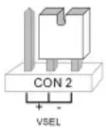
10.4.4 CON2
CON2 (D) jumper must be in the “-” position (factory setting).
10.4.5 DIP switch SW6
DIP switch SW6 (E) is factory-set as follows.
The individual switches of this 8-position DIP switch enable you to choose from the following options. Switch positions 4/5/7/8 must remain in the factory settings to guarantee correct functionality.
| Switch | Options | Factory setting | “OFF” position | “ON” position |
| 1 | Supervision | ON | Off | |
| 2 | Supervision | time ON | 3 hours | Strong 20 min |
| 3 | Jamming detection ON | Off | ||
| 4 | OFF | |||
| 5 | ON | |||
| 6 LED mode | OFF Display on Display off | |||
| 7 | OFF | |||
| 8 | Acoustic signal ON | Off | ||
On
On
10.4.6 CON3:
CON3 (F): This jumper is used to switch on the installer mode of the FU8220 external siren.
(The installer mode is deactivated in the factory default setting.)


This mode is useful for changing the battery. You can open the housing without the siren emitting any sound. The Secvest IP must also be in the “training mode” to suppress e-mail notification. („System → Maintenance“)
10.5 Setting elements and connections on the IP board


- System reset button
- Restart button
- NO
- NC
- COM Relay outputs
- Burglary
- Fire
- Panic
- DSL monitoring
- 0 V Transistor outputs
-
- terminal for power supply unit
-
- terminal for power supply unit
-
- terminal for battery connection
- – terminal for battery connection
- LAN network connection
Via web server: the system can also be restarted at "System → Maintenance → Restart system".
Restart button (2): this starts the IP module again and the network connection. Hold down the button for about 10 seconds.
10.6 Restoring the factory settings
To completely restore the alarm centre to the factory settings, you need to reset both the IP side and the wireless side.

Only reset one of the two sides and keep the settings of the other side. For example this means, if you only reset the IP side, then you don't need to train the wireless components again.
IP board:
- System reset button (1): this lets you restore the factory settings of the hardware
on the IP module. This means all the settings you have made with web server will be lost. To do this, hold down the button for about 10 seconds (then the LED goes out and the factory settings are restored). - Via web server: on the web server, at System → Maintenance → Restore factory settings, you can also reset the settings made on the web server.

Please note that the network settings are also deleted, the alarm centre is then no longer available through the usual IP address.
Wireless board:
-
Press SELECT on the wireless PCB until the eighth LED from the bottom lights up.
-
Push the SET button once to get to menu 8. All blue LEDs start flashing. This signals that the wireless module is ready to restore itself to the factory settings.
-
Press and hold down the ESC/DEL button for about 4 seconds until the flashing stops and the alarm centre beeps twice.
The factory settings are now restored. You are now in the main menu again.

The web server settings are retained. Only all the trained wireless components and their settings are removed.
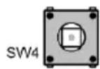
To exit programming mode, press ESC/DEL until the alarm centre starts to beep (about once per second). Close the housing or press and hold down the cover tamper contact (SW4, underneath ESC/DEL) for about 4 seconds until it beeps twice. The data is saved in an EEPROM.
10.7 Relay and transistor outputs
The relay output allows wired components to be switched. Maximum switching power: 1,25 A ; 60 VDC
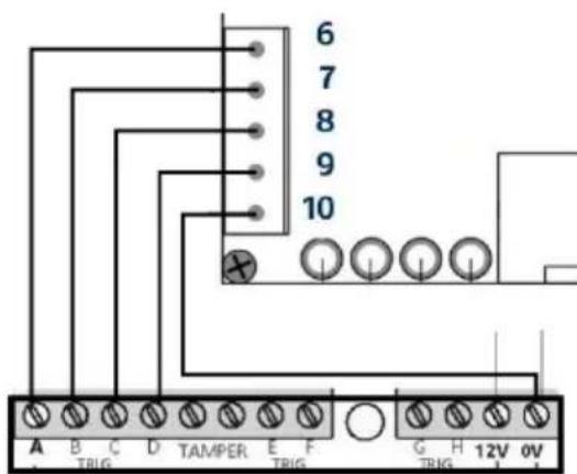
The transistor outputs are used for connecting an optional GSM dialler. Swiching power: 200mA.
Select a positive trigger polarity for controlling a GSM/PSTN dialler. Connect the 0V with the 0V of your dialler to establish equipotential bonding. In an activated state, the output is at 12V. For the numbering, refer to the chapter on “Setting elements and connections on the IP board”.

Power supply for the GSM/PSTN dialler is not possible using the Secvest IP power supply unit included.
11. Labelling the Secvest IP
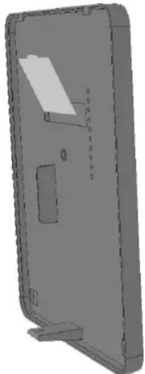
We recommend using the editable PDF on the supplied CD for labelling your Secvest IP, or downloading the PDF for the corresponding product from our website. Labelling the device is very simple. Enter your individual component settings in the PDF and print it out. Insert the cut-out label into the corresponding gap on the inner side of the cover.

We recommend using common, easy-to-understand abbreviations for the detector type (e.g. MC = magnetic contact, MD = motion detector, SD = smoke detector, VD = vibration detector, GD = glass breakage detector, FD = flood detector).
Next, describe the location where the detector is found. This helps to identify the detector quickly and easily in the event of malfunctions (e.g. empty battery). Remember that the name must correspond to the actual programming.
natural_image
3D CAD model of a rectangular mechanical part with cutouts and mounting base (no text or symbols)| 4 Detector / Zone 1 | 11 Detector / Zone 3 |
| 3 Detector / Zone 1 | 10 Detector / Zone 3 |
| 2 Detector / Zone 1 | 9 Detector / Zone 3 |
| 1 Detector / Zone 1 | 8 Detector / Zone 3 |
| Operating unit 3 | 7 Detector / Zone 2 |
| Operating unit 2 | 6 Detector / Zone 2 |
| Operating unit 1 | 5 Detector / Zone 2 |
12. Putting into operation
Connect the alarm centre directly to your computer using a LAN (cross-over) cable, or connect it to your network using a LAN cable. The factory-set IP address on the alarm centre is 192.168.0.50.
13. Enclosed software
The Secvest IP Finder is used to identify the Secvest IP in the network. It allows the corresponding IP address of the components located in the network to be determined. Install and start the IP Finder. You will find it on the accompanying software CD.
Click Search – the program will search the network for any connected network devices. Once the search is finished, a list of devices found on the network is shown. You will now see the network address of the Secvest IP. Enter the IP address in your web browser to access the alarm centre.

14. Configuration of the web server
When accessing the Secvest IP over your web browser, you can configure the Secvest IP using the integrated web server in the alarm centre.
14.1 Login
In order to change the settings on the Secvest IP using the web server, you must first log in to the web server as follows:
- Select your language
- Enter your user name (default: "admin")
- Enter the password (default: "12345678")
- Click on "Login"

If the user name and password are entered correctly, the "Overview" screen is accessed.
14.2 Overview
The “Overview” screen shows the current status of the Secvest-IP alarm centre, and is divided into three areas:
1. Inputs:

In the Inputs area, you will see an overview of the state of the three wireless zones (1) and three virtual IP zones (2).
The colour of the respective LED signalises the current status of the zone:
Green indicates that all detectors in the corresponding zone have not been triggered or are closed.
Red indicates that one or more detectors in the corresponding zone have been triggered or are open.
Grey indicates a deactivated or hidden zone, or a zone where no detectors are connected.
Yellow indicates a fault in the connection to the virtual IP zone (vZone) – e.g. the connection is lost to a connected PIR IP camera or an IP alarm module.
Creating/displaying/downloading live snapshots from PIR network cameras
Under “Inputs”, live snapshots from trained PIR cameras can also be viewed and downloaded if required. This feature allows the ACTUAL status of a zone monitored by a PIR network camera to be checked.

By clicking on the name of the zone for the required PIR network camera, 9 live snapshots are created at a delay of approx. one second and displayed in an overview menu.

By clicking on one of the pictures in the overview menu, the individual snapshots open and the specific picture is displayed in an enlarged format. You can scroll through the 9 snapshots using the arrow symbol (left and right of the image).
The 9 snapshots can be downloaded by clicking on "Download", and saved.

The snapshots can also be downloaded as TAR archive. Ensure that a TAR compatible data compression program is used to unpack the archive (such as WinRAR or 7 Zip).
Bypass a channel via the Overview Menu
In the Input area you also can easily bypass a channel. This function allows you to take out one channel with its learned detectors, so that these will not trigger any alarm. If you set bypass for a channel, this will be valid for the next activation of the alarm panel.

To bypass a channel, click on the Status-LED of the channel you want to bypass. (like shown in the screen shot). Tick the bypass button to "On" and click "Apply". The Status-LED will turn gray. If you would like to undo the bypass, so click again on the Status LED and choose "Off" and also click "Apply" to confirm. If you set a channel on Bypass "On", this channel will not detect any alarm for the next activation of the alarm panel. After the next deactivation, the channel will be automatically set on bypass "Off".
2. Outputs:

The Outputs area lets you switch the two wireless switching outputs (1 and 2) and the relay output (3). The current status can also be determined at this time. If the LED on the button lights up and the lettering has a blue background, this indicates that the output is currently switched on (see (1)).

The outputs can only be switched manually if the "Manual" event has already been selected at "Outputs". Make sure that all the other events are deactivated when selecting "Manual".
3. Alarms:
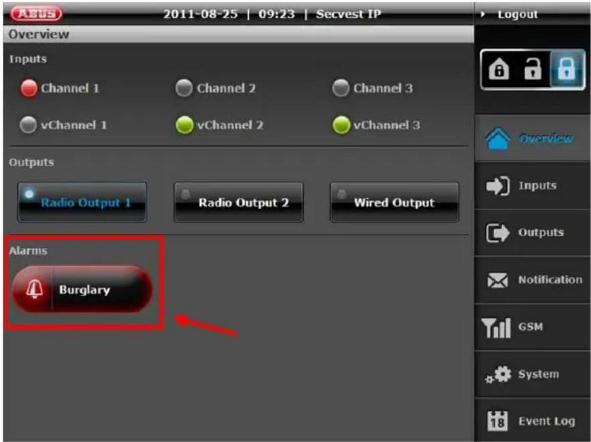
The Alarms area is used to indicate whether any alarms are present (and if so, which ones).
Possible Alarms:
Burglary
Fire
Panic
Technical
Fault
- Jamming
- Supervision
- Tampering
- Battery fault
- Power failure

System faults can only be cleared by rectifying the cause.
If a panic, fire or technical alarm occurs in the deactivated state, it can be reset by clicking the alarm message in the overview.
4. Web server acoustic signalling
If the alarm centre is activated/deactivated, or if an alarm is triggered, the web server sends acoustic feedback to your web browser. (If an alarm is triggered, an additional siren alarm signal is emitted until the alarm is reset/the centre is deactivated)

The acoustic signaling in the web browser is only possible on HTML5-compatible browsers: Internet Explorer 9 (or above), Firefox 4 (or above), Safari 5 (or above). Audio playback on iPhone, iPod or iPad Safari browser is not possible for reasons of compatibility.
14.3 Inputs
Name the inputs according to the detectors that you want to train. Select the attributes and the associated alarm type.
To go back to a higher level menu from a submenu, press the corresponding buttons on the selection bar on the right.

14.3.1 RF-Inputs
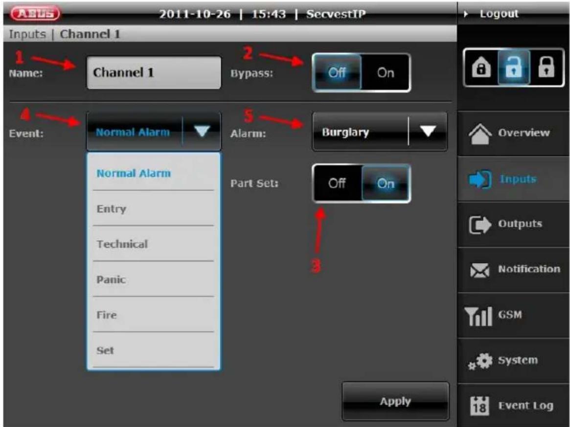
-
Name: Name of the zone/specification whose name is used in the zone display in the "Overview" menu.
-
Bypass (on/off): The selected zone is hidden (i.e. zones can be deactivated). This function can be used to bypass specific zones and their detectors, when necessary (e.g. when the detector indicates an empty battery or a detector in the zone cannot be connected). The bypass is only activated for one arming procedure, and is then automatically reset.
-
Internal activation: Using the internal activation setting, you can define whether the affected zone is monitored by internal activation of the alarm centre. To enable the zone to be internally activated, the regulator must be put to "On". After internal activation, only the monitored zones are shown in the overview. All the remaining zones are deactivated in this mode and displayed in grey.
4. Event (zone attribute):
Zones can have very different attributes. The assignment is made according to the type of trained detectors on the zone. The detector sends an alarm notification to the alarm centre, which then triggers a reaction depending on the set event properties and alarms.
The following alarm events can be defined:
- Normal Alarm: When the alarm centre is activated, this zone triggers a burglar alarm if one of the detectors has been triggered. Good examples for this zone attribute include the training of motion detectors, magnetic contacts or PIR network cameras.
- Technical: One of the zones with this attribute triggers a technical alarm when the alarm centre is deactivated and activated. Use this zone type for flood detectors, for example.
- Fire: This zone always triggers an alarm, irrespective of whether the alarm centre is activated or deactivated. Use this zone attribute when smoke detectors have been trained here.
- Entry: If the burglar alarm centre is active, this zone triggers an alarm following a specified delay time (entry delay). This zone attribute can be used for a magnetic contact on the entrance door.
- Set/Unset: A zone can be used for activation and deactivation with this zone attribute.
-
Panic: This zone always triggers an alarm, irrespective of whether the burglar alarm centre is activated or deactivated. Train panic detectors on this zone, for example.
-
Alarm (alarm reaction of the zone): Definition of which reaction is triggered by an incoming event.
-
Deactivated: Alarm is deactivated, the event does not trigger an alarm.
- Burglary: Burglar alarm – can be signalled by an optical or acoustic signaller. A corresponding alarm notification is also sent by e-mail, depending on the settings.
- Fire: Fire alarm – alarm is made by siren as pulsed alarm tone. A corresponding alarm notification is also sent by e-mail, depending on the settings.
- Silent: Silent alarm – in the event of a silent alarm, the connected acoustic and optical signalling devices are not activated. The alarm notification is only sent by e-mail, depending on the settings.
- Technical: Technical alarm – alarm made by siren. A corresponding alarm notification is also sent by e-mail, depending on the settings.
To complete the configuration, click Apply.
14.3.1.1 Virtual Inputs (vChannel)
In the virtual inputs area, the settings can be made for connecting IP components. (e.g. PIR IP camera, IP alarm module).
As in the wireless inputs area, the virtual inputs can be concealed, the internal activation configured, as well as the event connected to the alarm.
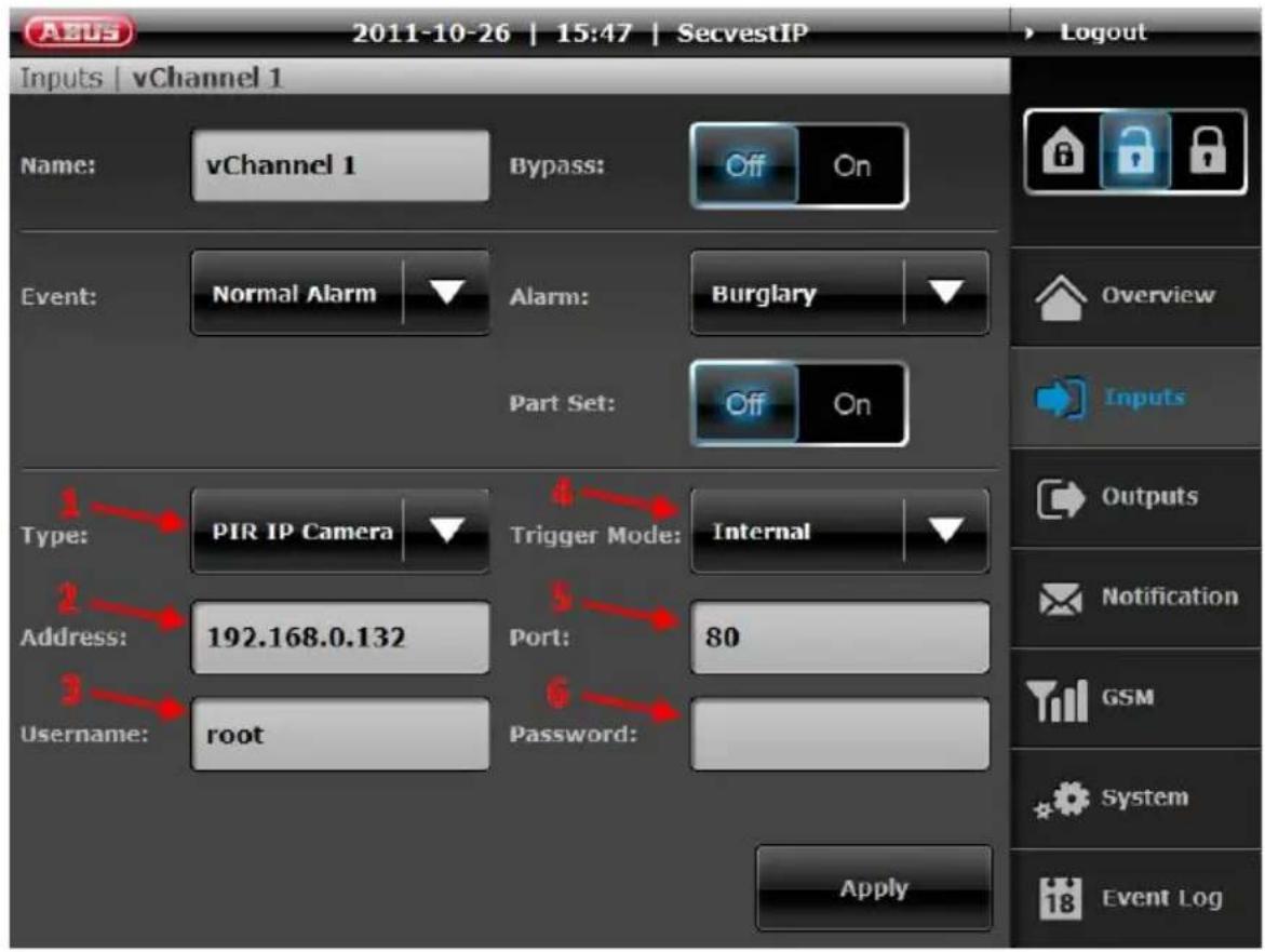
In addition, the following – virtual IP-zone specific settings – can be configured:
- Type: select which IP components in the virtual zone should be trained. PIR IP camera = TVIP41550
IP zone 1 = IP alarm module – input zone 1
IP zone 2 = IP alarm module - input zone 2
Only one IP alarm module can be trained for each alarm centre.
-
Address: enter the IP address of the components connected here.
-
User name: user name for accessing the connected component (here: standard user name for the PIR IP camera = "root" / standard user name of the IP alarm module = "admin"). For more details, refer to the user manual of the connected component.
4. Sensor:
Internal setting: the network camera sends a warning via the internal PIR sensor and has a warning function only.
External Setting: the network camera is in the recording mode and reacts in the alarm centre in the event of an alarm.
- Port: enter the network port of the connected component.

When using the IP alarm module, the HTTP port number is always 8081 and cannot be changed.
- Password: password for accessing the connected component. (standard setting for the PIR IP camera = password not assigned/standard setting for IP alarm module = 12345).
To confirm your settings, please press "Apply".
14.4 Outputs

Name the outputs according to their wireless programming and link them to events.
Example: Radio Output 1, which controls a wireless socket with is connected to a light, this will be switched on in case of an alarm.

By ticking the boxes under "Event(s)", the user has the option of specifying which events switch the outputs (e.g. so that the light is switched on). The following events can be selected.
- Burglary
- Fire
- Low Battery
- Manual Event (must be ticked on in order to enable manual operation via "Overview"-Screen).
- Panic
- Power Fail
- Set (Radio Output actives, when alarm centre is activated)
- Trouble
- Unset (Radio Output actives, when alarm centre is deactivated)
The outputs can only be switched manually if the "Manual" event has already been selected at "Outputs".
- Duration: The option duration enables you to choose between permanent output triggering (until next status change) or triggering of output for specified time frame.
- Scheduler: The option scheduler enables you to assign a scheduler to this specific output. The assigned scheduler will be active at the same time with enabled events. In case of simultaneous triggering based on scheduler trigger and event trigger the latest trigger event is valid.
To complete the configuration, click Apply.
There will be more information regarding „scheduler“ in next chapter.
14.5 Scheduler
In the scheduler area you can configure automated SET / UNSET schedulers along with schedulers to program time-controlled triggering of outputs.

The schedulers will be devided into following types:
Scheduler 1-2: Scheduler to arm/ disarm the alarm panel.
Scheduler 3-6: Scheduler to control outputs.

Scheduler 1-2 and 3-6 have no fixed allocation. The schedulers will only active once assigned to an output or user.
Scheduler 1-2 configuration:

Each scheduler can store up to 5 individual triggering events. The column "Set" defines time to arm the panel, the column „Unset“ defines time to disarm the panel.
You can configure an individual name within input box for „Name“. This will help later on to assign schedulers more easily.
Each trigger time is easily configured by clicking into the cell which will bring up a new window for data input.
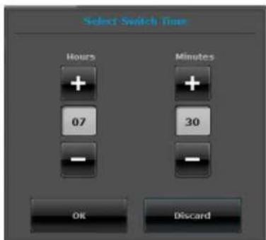
If there is no time configured to "Set" or "Unset" state (--:--) no action will be taken. This enables you to allow doing only a "Set" or "Unset" command at a specific time.
Please choose at least one day by clicking on checkbox to activate the scheduler. You can click on scrap symbol to delete a row including triggering events.

By arming the alarm panel via scheduler, all wireless zones will automatically omitted within set operation.
Application examples:
Set: 19:00
Unset: 07:30
Cycle: Mon, Tue, Wed, Thu, Fri
Effect: The alarm panel will disarmed at 07:30 a.m. and armed at
7.00 p.m in the evening. The scheduler will be valid within
Monday to Friday.
Set: 16:30
Unset: 09:00
Cycle: Sat, Sun
Effect: The alarm panel will disarmed at 9.00 a.m and armed at
4.30 p.m afternoon. The scheduler will be valid within
Saturday and Sunday only.
Set: 19:30
Unset: --:--
Cycle: Mon, Tue, Wed, Thu, Fri
Effect: The alarm panel will arm the system on a daily basis form
Monday to Friday at 7.30 p.m only.
Assign Scheduler 1-2:
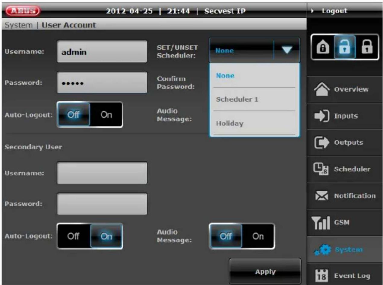
In user account configuration area System → User Account you can assign scheduler 1 or scheduler 2 for automated arm- and disarming of Secvest IP alarm panel. The individual scheduler name will shown in dropdown list.
Please press Apply in order to save the configuration data and to activate the scheduler.
Scheduler 3-6 configuration:

Each scheduler can store up to 5 individual triggering events. The column “On” defines time to activate the output, the column „Off“ defines time to deactivate the output.
You can configure an individual name within input box for „Name“. This will help later on to assign schedulers more easily.
Each trigger time is easily configured by clicking into the cell which will bring up a new window for data input.

The following configuration can be applied to each trigger time:
| Hours Minutes Description | ||
| 08 15 | Trigger at 08:15 a.m. | |
| 08 | -- | Start triggering at 08:00 a.m.each hour until end of the day. |
| -- | 15 | Triggers on15th minute every hour. |
Please choose at least one day by clicking on checkbox to activate the scheduler. You can click on scrap symbol to delete a row including triggering events.
Application examples:
On: 19:00
Off: 23:59
Cycle: Mon, Tue, Wed, Thu, Fri
Effect: The output will triggered at 19:00 p.m until 23:59 p.m. The scheduler is valid from Monday to Friday.
On: 14:00
Off: --:--
Cycle: Mon, Tue, Wed, Thu, Fri
Effect: The output is triggered on a daily basis from Monday to Friday at 14:00 p.m only.
On: --:25
Off: --:50
Cycle: Sat, Sun
Effect: The output is triggered every 25th minute to on and every 50th minute to off. The scheduler is valid from Saturday to Sunday.
Assing scheduler 3-6:
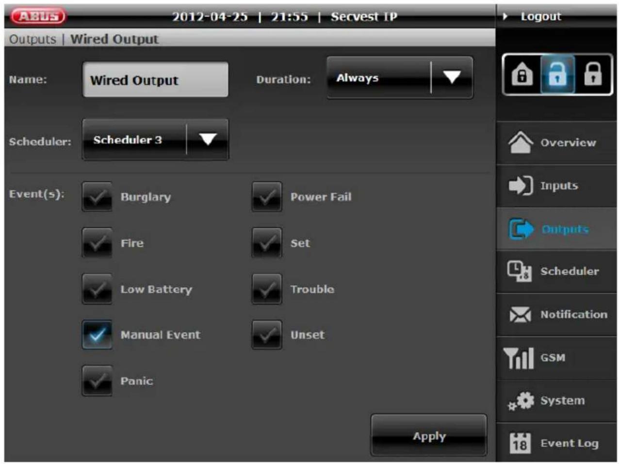
Within output configuration area you can assign the schedulers by clicking on "scheduler" dropdown list. You can assign the same scheduler to each output of your Secvest IP alarm panel at the same time.
14.6 Notification
In this menu, you specify the settings and rules for e-mail notifications.

The Notification menu is divided into six areas, which can then be used to adjust the notification function to your own requirements:
-
Email account: Server setting for sending emails
-
Messages: Defining email content
-
Recipient: Contact data (email address and SIP numbers)
-
Email rules: Link alarm event and email recipient
-
SIP account: Server setting for SIP notification
-
SIP rules: Link alarm event and SIP recipient

You can find information on the configuration of push notification in the "System → Push Notification" section.
1. E-Mail Account

The “E-Mail Account” area is used to enter the data of the account from which notifications are sent in the event of an alarm. Aside from the name and e-mail address, the contact information of the outgoing mail server, user name and password of the e-mail account must be entered. The address of the mail server and the port number can be found on the homepage of your e-mail provider. To check the settings made for function/correctness, click “Mail Test”.
The settings are saved by clicking Apply.
2. Messages

Text messages for the respective event type can be stored under the "Messages" menu item. These messages are then sent automatically to the corresponding e-mail addresses in the event of an alarm. To add a message, click "Add Message". A subject (e.g. "Burglary!") and a text (e.g. "A burglary has been committed!") can now be entered. A message can be deleted by clicking the waste bin icon. After all settings have been made and a message has been set for each event, the settings are then saved by clicking the Apply button.
3. Recipients

This menu item is used to enter one or more e-mail addresses where a message is sent in the event of an alarm.
To add a new e-mail address, click on "Add Recipient" and enter the name and e-mail address of the recipient. Repeat this process until all of the required recipients have been entered. Confirm the settings by clicking the Apply button.
Setting up an SIP account
An SIP or PSTN (landline) number can also be stored for each recipient who can be called in the event of an alarm. To obtain an SIP number, you need to register at an SIP provider (tested and approved by ABUS: http://www.sipgate.de or http://www.localphone.com) and receive your own/personal SIP number from there. Depending on the application, this needs to be entered in a certain format under “Telephone”:
1. Option: SIP to SIP telephony (free of charge)
Format: SIP number @ provider.URL
Example: 7897184 @ localphone.com
SIP to SIP telephony is free of charge. The provider of the “called” subscriber needs to be entered here as the provider (=recipient – provider).
In this case, the centre calls an SIP subscriber. For instance, this could be an IP phone, a Smartphone with SIP application or a PC with an in-built SIP telephone. This is purely network-based communication from the centre to end device. It takes approx. 20-30 seconds to make a connection from SIP to SIP.
2. Option: SIP to PSTN telephony (subject to a charge)
Format: international dialling code+local code+telephone
number@provider.URL
Example: +49 (0)8207 959900 @ sipgate.de

For SIP to PSTN telephony, the provider must be entered where the SIP account of the centre is registered (=sender – SIP provider). As the SIP to PSTN telephony is subject to a charge, (approx. 2 ct/min), the SIP account for this type of notification must contain a minimum amount (depending on the provider).

In this application case, the centre first calls your SIP provider, which converts the conversation into an PSTN call. Then you are able to call any phone number from the landline. / the connection from SIP to PSTN takes roughly 45 seconds.
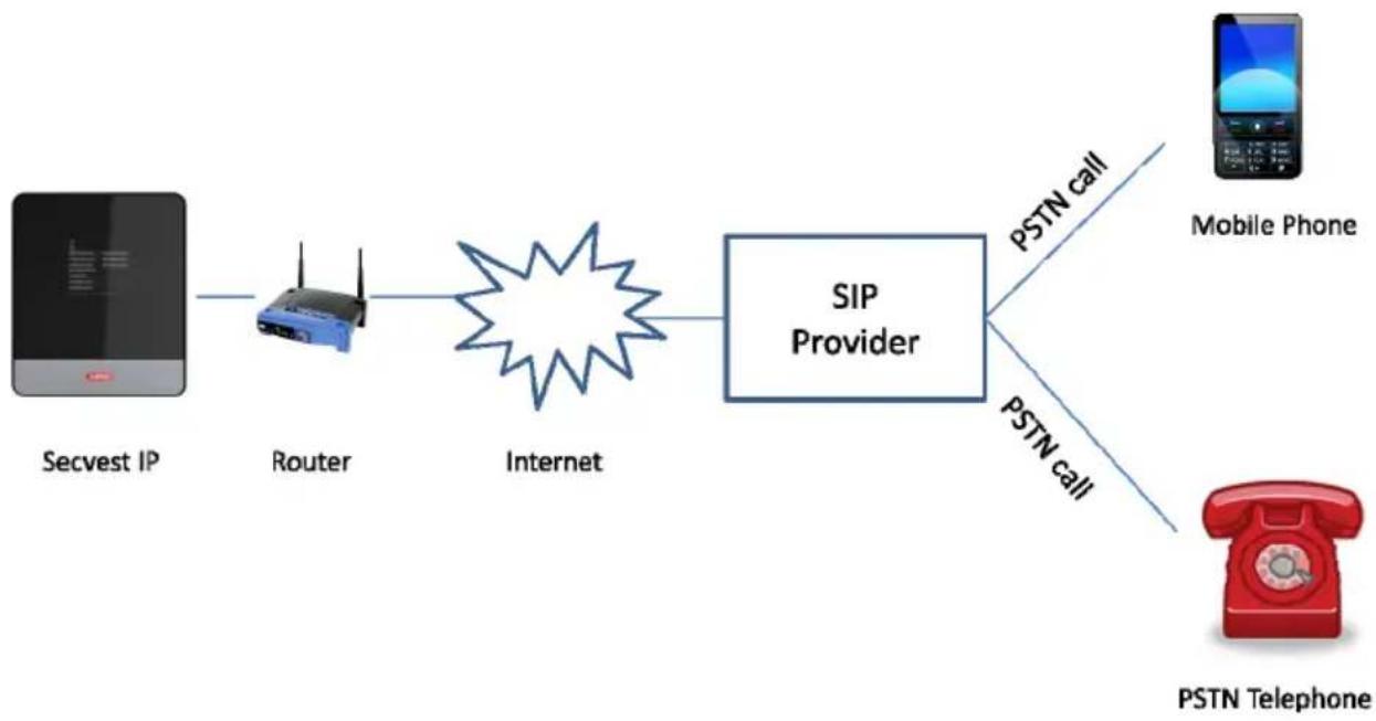
flowchart
graph LR
    A["Secvest IP"] --> B["Router"]
    B --> C["Internet"]
    C --> D["SIP Provider"]
    D --> E["PSTN call"]
    D --> F["PSTN call"]
    G["Mobile Phone"] --> H["PSTN Telephone"]
You can find out more details on SIP under points 5 & 6. (SIP account and SIP regulations)
Confirm the settings by clicking Apply.
4. Email Rules
Under “Email rules”, rules are defined by which a message and one or more recipients are clearly assigned to each event (alarm).

For setting up the email notification, click an event for which a rule should be created (e.g. "Burglary"). A new rule is then created by clicking "Add rule".
Click in the blank "Message" field.

One of the previously saved messages can then be selected and assigned to the "Burglary" event in the window which opens ("Select Message"). Confirm your selection by clicking "OK". Recipients must now be assigned to the defined message for the "Burglary" event by clicking the empty "Recipients" line.
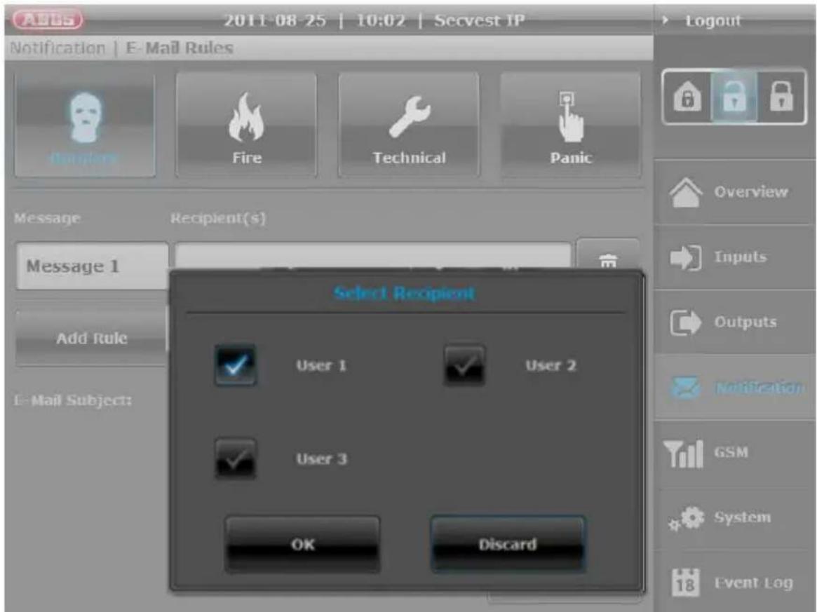
The recipient can be selected by ticking the box in the window which opens ("Select Recipient(s)") and then confirmed by clicking "OK". All changes must be confirmed by clicking "Apply", otherwise the settings are lost.

In the “Email subject” field, you also have the option of creating an individual subject for the email notification of the respective centre. It is advisable to enter a subject which makes assigning the alarm message easier. The standard setting for the subject line is “Centre name – event name” (Secvest IP burglary). You can change the text by entering the text field. By clicking on the waste paper bin symbol, the individualized subject is reset to the standard one.
5. SIP Account
Under “SIP account”, the SIP telephony is activated/deactivated as well as configured. For the activating option, the centre can make a Voice-over-IP call in the event of an alarm. The following requirements must be in place to do this:
- Registered SIP account for your centre at an SIP provider
- SIP "On" function
- Valid "Number" (for SIP-to-SIP SIP-to-PSTN) in the recipient area
- Configuration of SIP call for alarm (SIP rules)
To activate SIP telephony, move the regulator to "On". You obtain the domain, user ID and password when your provider creates your SIP account.
Providers tested by ABUS:
√ http://www.localphone.com
√ http://www.sipgate.de

Depending on provider, nomenclature of user ID and password can be different:
Passwort = SIP-Passwort
Localphone.com → Login → Account:
Passwort = SIP Password
→ see also point “3. Recipient → Setting up an SIP account”
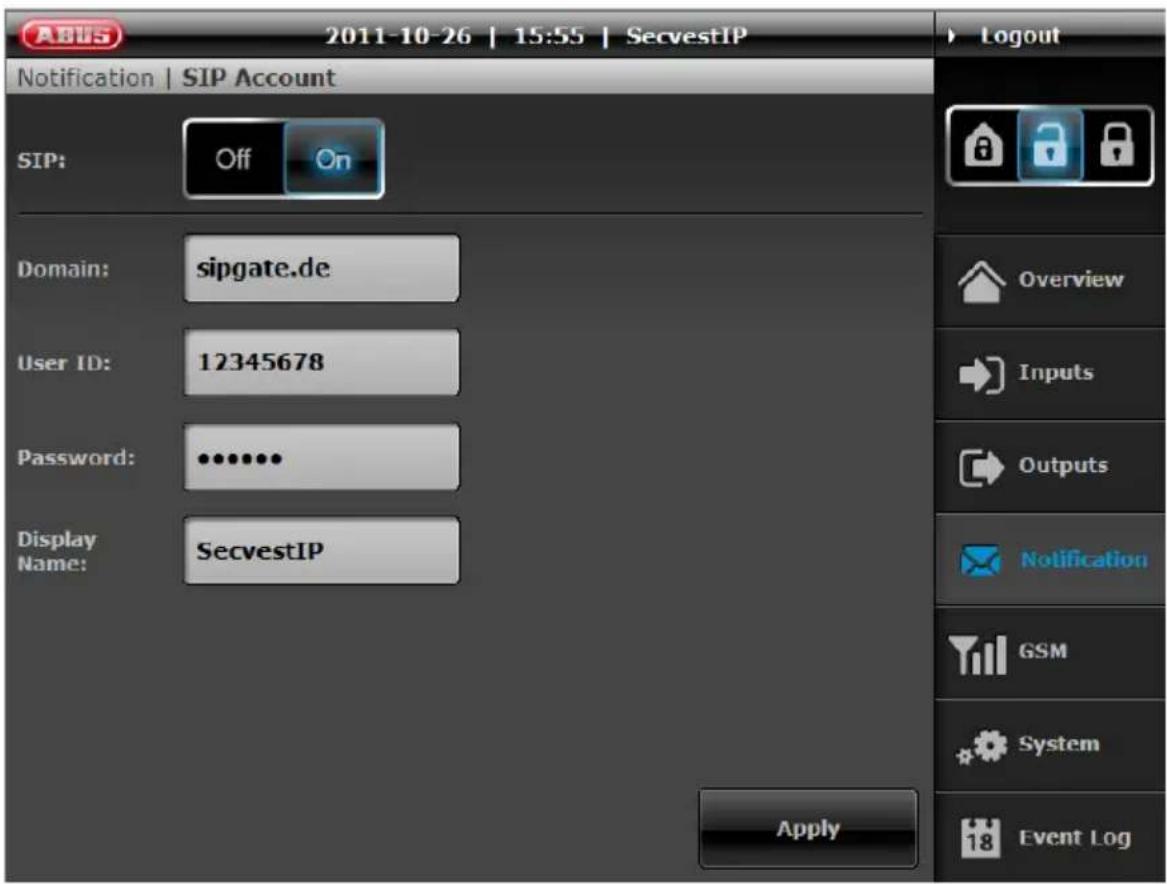
The name of your SIP account can be assigned individually.

See also [page 45] → Network → „Troubleshooting SIP-dialing“
6. SIP Rules
As under "Email rules", "SIP rules" can also have links set up from alarm events to the recipients who should be called or contacted via SIP telephony in the event of an alarm.
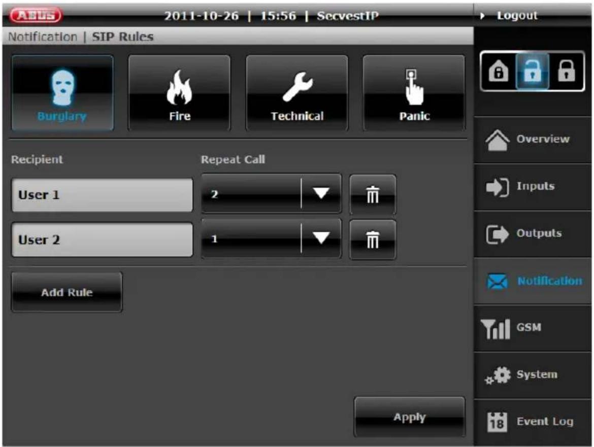
For setting up the SIP notification, click an event for which a rule should be created (e.g. "Burglary"). A new rule is then created by clicking "Add rule".
Click in the "Recipient" field.

One of the previously saved recipients can then be selected and assigned to the “Burglary” event in the window which opens (“Select Recipient”). Confirm your selection by clicking “OK”.
Next, the number of redials per recipient can be defined which are made when there is no response to a call. All changes must be confirmed by clicking "Apply", otherwise the settings are lost.
If the first defined recipient does not respond to a call, then the next defined recipient is called. If this recipient does not respond either, another attempt is made to call the recipients on the list (as often as is defined in "Redialling"). If one of the recipients responds to the call, they will be played the respective alarm message for the event.
Example – complete call list (redialling):
Recipient A (1) → Recipient B (1) → Recipient C (1)
Recipient A (2) → Recipient B (2) → Recipient C (2)
Recipient A (3) → Recipient B (3) → Recipient C (3)
Example – recipient A responds to the second round and deactivates the alarm:
Recipient A (1) → Recipient B (1) → Recipient C (1) Recipient A (2)
All the recipients are called until the alarm centre has been deactivated. Deactivating the alarm centre terminates the calling process.
14.7 Activating / deactivating the alarm centre / Internal activation
These buttons let you activate/deactivate the control centre (guard mode "on" or "off").


The system can also be activated internally. This type of activation is normally used to monitor the exterior of the object when it is still occupied. In this case, specific detectors within
the object, such as motion sensors are removed from surveillance.

An internal activation is not possible via remote control!
14.8 GSM
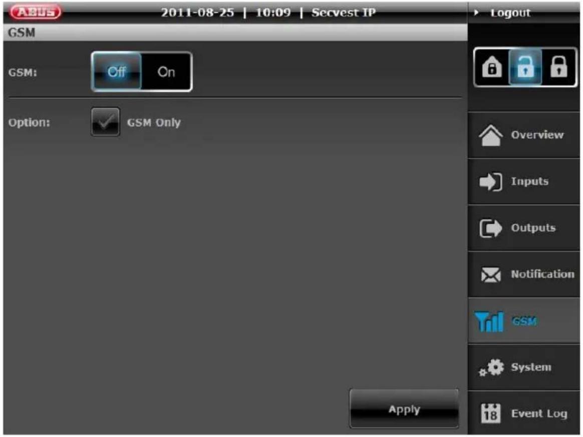
Settings can be made here for using an optional GSM dialler (AZ6302) to set up a redundant communication path. To use a GSM dialler, switch GSM to "On". The transistor outputs are now also controlled. To receive notifications exclusively via GSM, tick the "GSM Only" box. Confirm the settings by clicking the Apply button.
14.9 System
This menu item is used to configure the network settings, set the date and time, manage users, change the language and perform maintenance on the alarm centre itself.

Settings for push notification and SD card can also be made.
1. Network

The "Mode" selection box is used to specify whether the IP address is taken automatically from the DHCP server or is assigned manually by the user via static IP. Select the appropriate setting according to your network properties.
Troubleshooting SIP-dialing


Set Network mode of your alarm panel on "Static IP" and configure DNS server IP address on Google DNS server IP "8.8.8.8" (see above), if there occurs an error or SIP call is not transmitted in case of an alarm.
2. Date & Time

Set the time and date here. Selection options available:
- NTP mode Time and date are obtained from an NTP server via internet. Several NTP servers can be selected here.
• PC mode time of the PC. Time and date are synchronized with the system - Manual mode Time and date can be set manually.
The applicable time zone can also be selected. Make any changes as usual with "Apply".
3. User Account
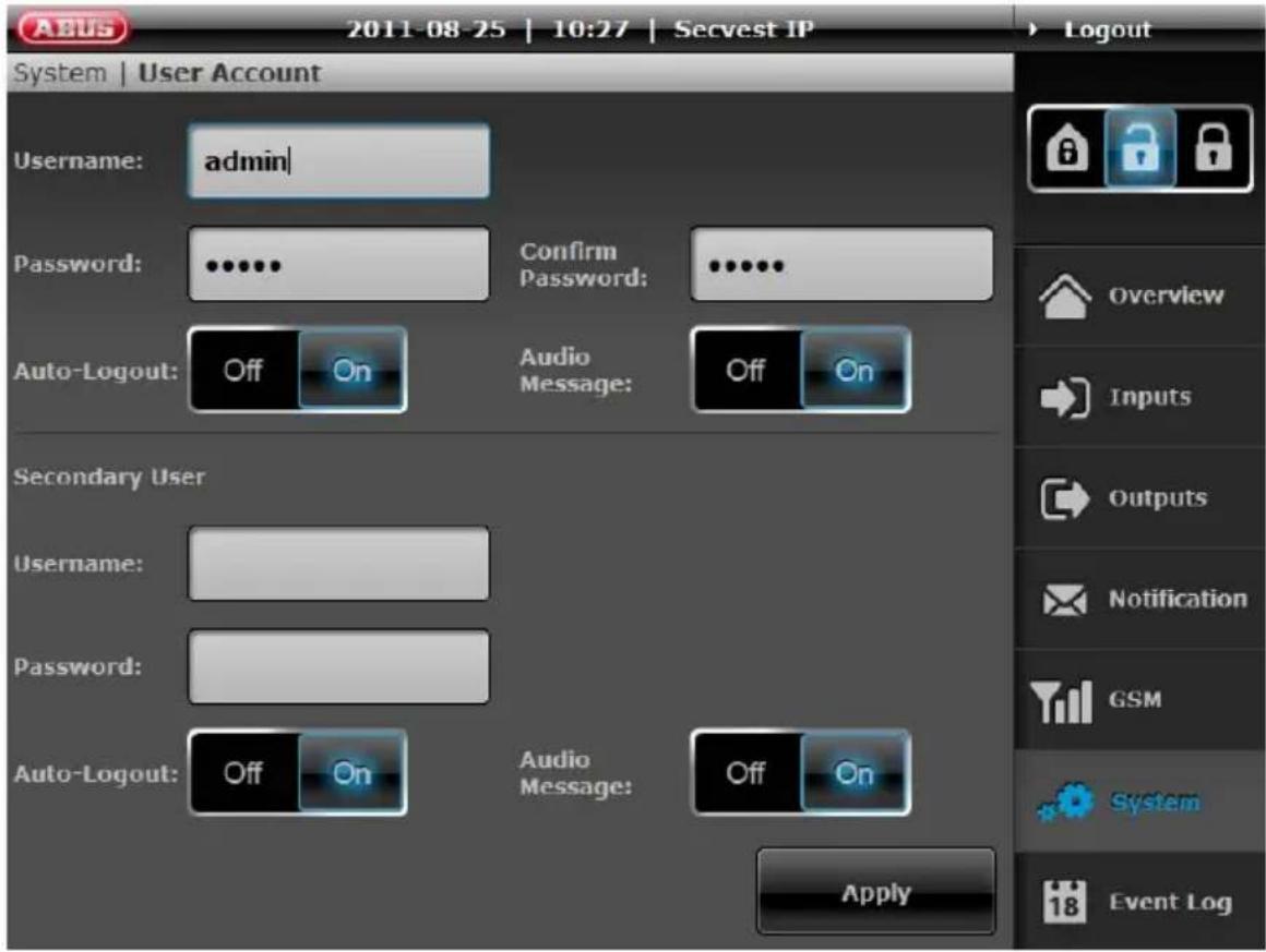
Two user levels can be implemented here. All setting options on the alarm centre are available on the first user level. The second user level only has the option of activating/deactivating the alarm centre or resetting the alarm and viewing the log book. This prevents the programming from being changed by every user. Make sure that no spaces or special characters are used when selecting a password and a user name.
Additionally, “Automatic log out” can be activated / deactivated and “Audio messages” can be switched on or off for both users.
• Automatic log out The user is automatically logged out after a certain time on the web server to prevent the user from staying logged in unintentionally.
- Audio messages Audio messages are adjusted according to the selected system language. The user receives acoustic feedback when the alarm centre is activated/deactivated and when an alarm is triggered.
Make any changes as usual with "Apply".
4. Language

The corresponding system language is set here. When you change the system language, the audio signalling is also automatically adjusted to the new language.
5. Maintenance (training mode / firmware update)

The “Maintenance” menu item is used to change the system name, make a firmware update, restart the system, switch to the training mode or reset the system to the factory settings.
Firmware updates
To update the firmware, click on “Browse” to select the update file on your computer. To start the update, click “Install”. The update process can take several minutes – never terminate the connection between your computer and the Secvest IP during this time. The system is restarted after the update is completed.
Factory Settings
The IP module default parameters are restored, which means that all the settings made with the web server will be lost.
Restart
This starts the IP module again and the network connection. Settings and trained detectors will not be lost and do not have to be retrained.
Learn Mode
The system can be set to "Learn Mode", to deactivate the alarm reaction of the alarm panel.

This means that detectors can be triggered and tested in this mode, but an alarm reaction cannot be triggered. This is particularly suitable for training wireless components or for maintenance.
Note that this mode must be set to OFF to train wireless sockets.
6. Push Notification
The end devices that have been registered and set up for push notification in the alarm panel are displayed here.
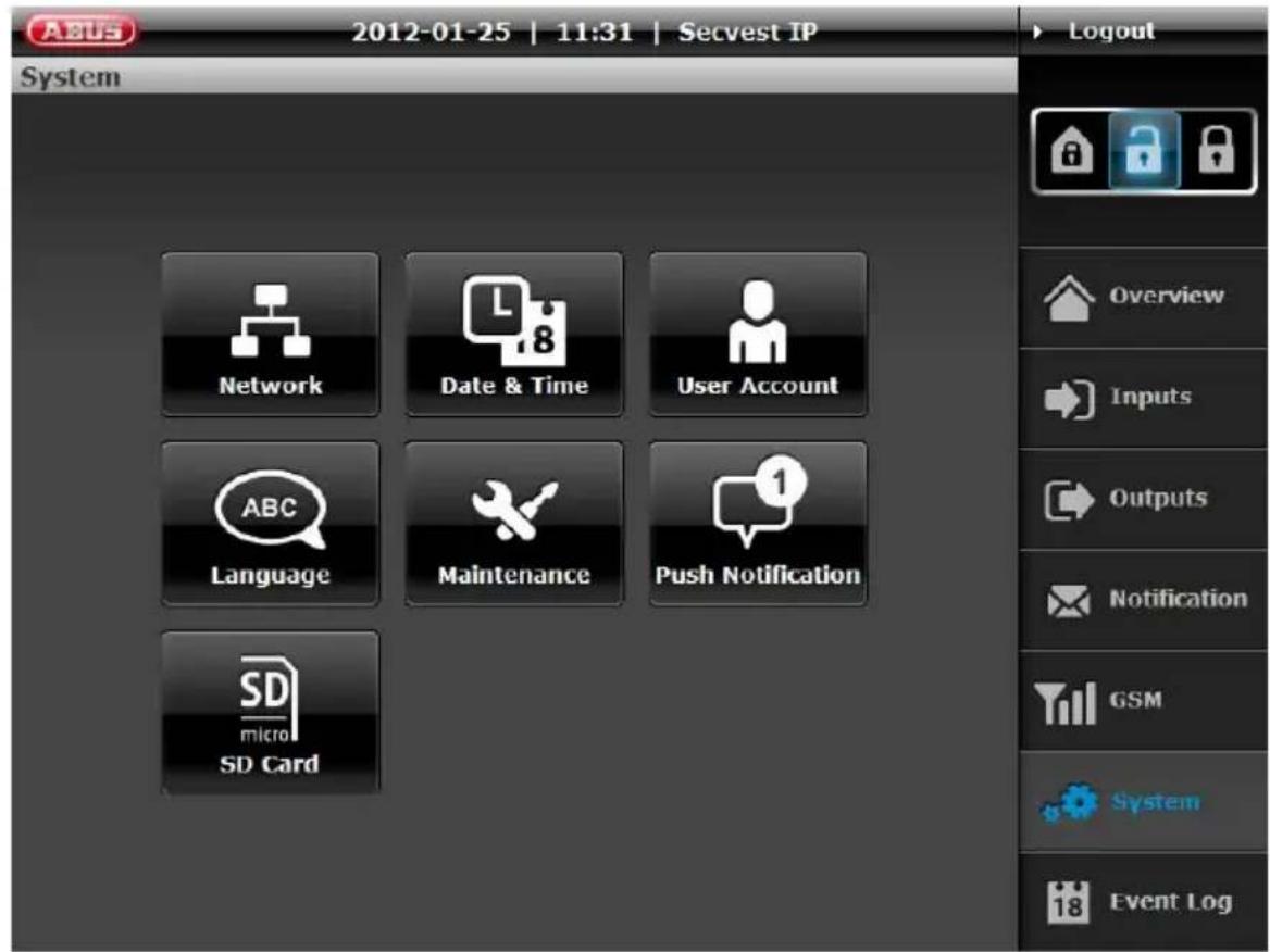
Click "Push Notification" to display the detailed view of the registered end devices on the control panel.
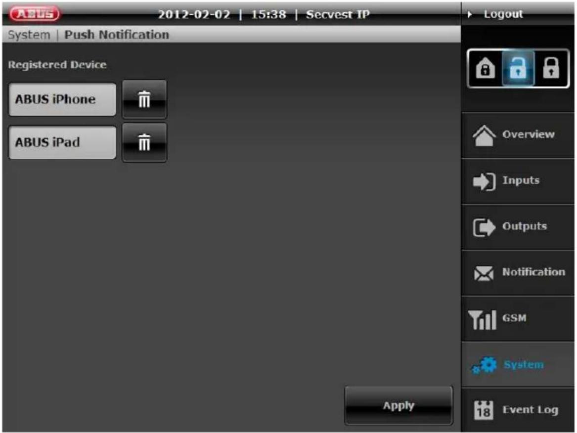
If no end devices have been set up (iPhone, iPod, or iPad), this list will be empty. The registration (pairing) of an end device can be carried out on the control panel using version 2.0 or higher of the Secvest IP app and control panel firmware version 2.0.5 or higher.
To do this, the Secvest IP app reads the internal device name (such as ABUS iPhone) and transmits it directly to the control panel. If the device name has changed, you can update the name displayed on the control panel by repeating the “pairing” process.
Up to six devices can be registered on the control panel for sending of push notifications. In case of alarm (intrusion, fire, panic, technical), the control panel sends a push notification to all registered devices. This notification is coupled with an audible warning signal that is issued in parallel.

The Apple Push Notification Service (APNs) is provided directly by Apple Inc. The service is used to issue an alarm on the basis of a network connection between the Apple push server and the end device with activated push service without it being necessary for the actual application (Secvest IP) to be started. The push service is not a guaranteed medium made available by the ABUS Security Center. Push notifications can arrive late, be discarded, or not be delivered by Apple.

Push notifications usually arrive within the first 10 seconds after an event is triggered on the control panel, but immediate delivery by Apple is not guaranteed. If the target device is offline at the point in time of the delivery, the push notification on the APNs server is cached for later delivery.
Setting up the push pairing process between the app and control panel
Adding a new control panel:
- Load Secvest IP 2.0 or higher from the iTunes App Store onto your end device.
- When the app first starts, confirm the activation of receipt of "push notifications" from Secvest IP.
- Use the setup wizard to add your Secvest IP control panel.
- Press the "Push Pairing" button during the last setup step (on the finish page) and wait for a confirmation from the control panel (notification window).
- Your control panel, app, and end device are now configured for push notification.

The control panel has already been added to the app:
(update from 1.5.2 to 2.0 or higher)
- Load Secvest IP 2.0 or higher from the iTunes App Store onto your end device.
- When the app first starts, confirm the activation of receipt of "push notifications" from Secvest IP.
- Navigate to the "Settings" menu item and select your control panel.
- Press the "Push Pairing" button in the control panel settings of the app and wait for a confirmation from the control panel (notification window).
- Your control panel, app, and end device are now configured for push notification.


Important information about the receipt of push notifications:
√ Flight mode must be deactivated.
√ The Secvest IP app must be closed.
√ Internet access (3G / WiFi) must be active on the end device.
√ The control panel must have Internet access.
√ The language setting of the push notification is according to the system language on the end device at the point in time at which the pairing occurred.
7. SD Card

Under "SD card", you can make specific settings for SD cards:
Memory: Shows the occupied memory on the SD card in relation to the complete capacity of the SD card. The standard capacity of the installed SD card is 2 GB – it can store a maximum of 500 events.

After formatting the SD card, the total memory of the SD card will not be shown as "free" again. This is because the audio files for acoustic feedback from the alarm centre are stored on the SD card.
Formatting the SD card: Caution! All pictures on the SD card will be deleted. Any information stored on the SD card will also be lost!
Exporting pictures: This feature enables you to export all the alarm events stored on the SD card. The data is exported to a TAR archive in the same way as for downloading live snapshots in the overview menu.

Ensure that a TAR compatible data compression program is used to unpack the archive (such as WinRAR or 7 Zip).
14.10 Event Log
This function enables the user to read the event log.

This log contains the events together with the date and time and event type. The sort sequence can be changed from descending to ascending order using the arrow at the top left.
All alarm events are shown as standard. If only one specific event type should be displayed, then select this in the menu at the top right.
Additionally, the event log can be deleted ("Clear"), updated ("Refresh") or exported into an external file ("Save").
In the column to the right of the event, the zone triggering the alarm is displayed. This gives you an overview of which zone the alarm detected:
C1, C2, C3 = wireless zones 1-3
vC1, vC2, vC3 = virtual zones 1-3
The last column on the right in the event log shows you the “triggered event”. If an alarm is triggered by a PIR network camera, the PIR camera symbol is displayed. The alarm pictures can be retrieved by clicking on them and can be exported to a TAR archive via “Download” if required. The date, time and triggered zone are also displayed in the alarm picture overview.
14.11 Logout
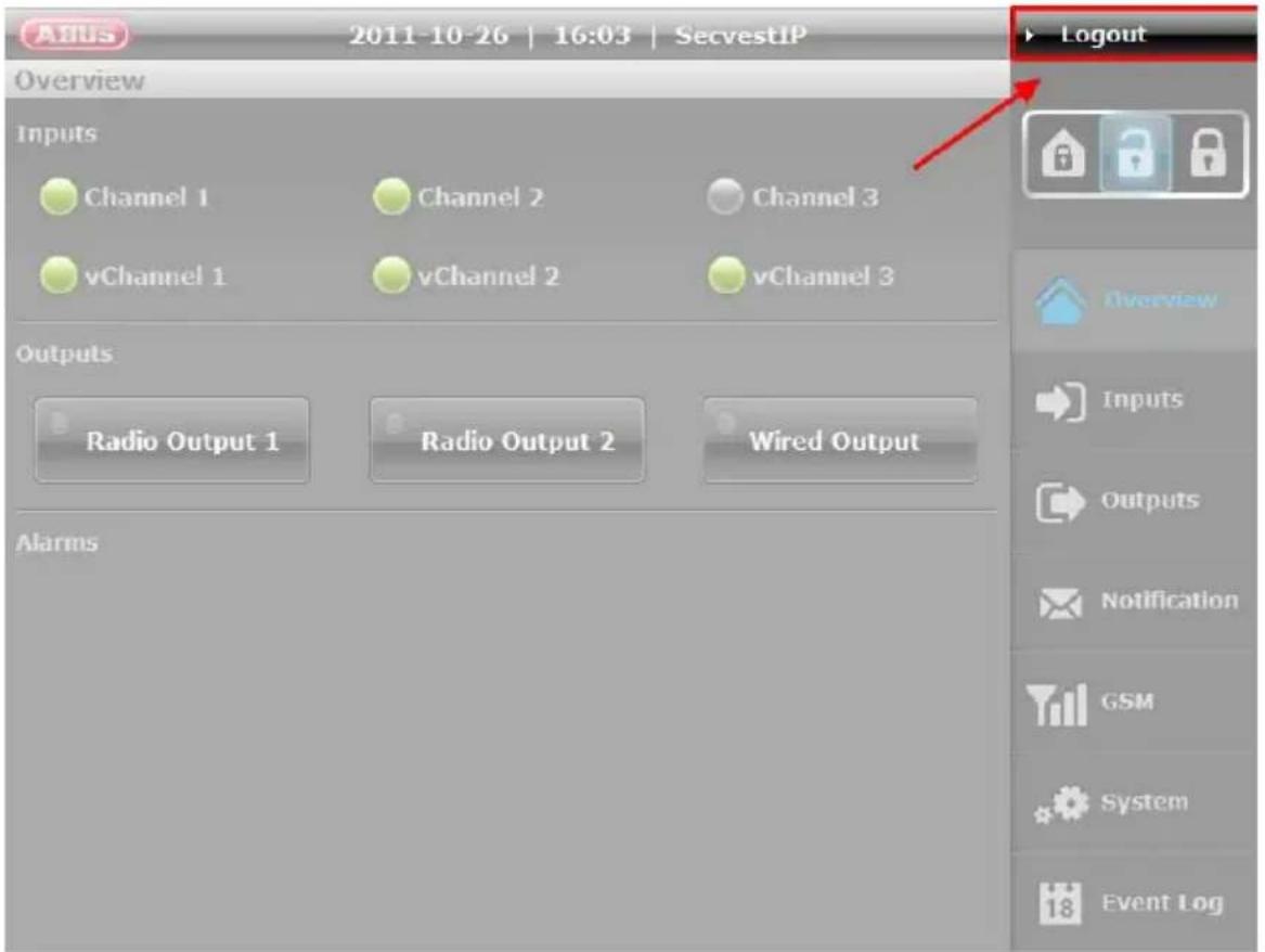
After the configuration is set or operation is finished, click on the "Logout" button at the top right of the screen to log out of the Secvest IP web server. This prevents unauthorized persons using this computer from making changes to the alarm centre.
15. Teaching the wireless components
Switching on: Connect the power supply. The alarm centre beeps twice and the top LED (green) lights up. Ensure that the tamper switches on the alarm centre are open. The “Trouble” LED flashes red with 1 Hz if the cover is open. To deactivate the wall temper switch, read the instructions below.
Programming: Press SELECT once to access programming mode. The main menu is accessed. The bottom LED lights up for menu 1.

For teaching wireless components, we suggest to activate the Learn Mode. This can be activated by the web server: System → Maintenance → Learn Mode → ON. (Username: admin/Password: 12345678)
In addition we recommend deactivating the wall tamper contact during programming. See the section on deactivating CON1 (C) for more information. Please ensure that the jumper is set according to your wishes after programming is completed.
Press SET once to access the menu – the LED goes out or flashes according to the individual menus.

Always close programming mode as described below to ensure that the new settings are saved.
Do not disconnect the power supply.
Press ESC/DEL until the alarm centre starts to beep (about once per second). Close the housing and hold down the cover tamper contact SW4 (B) for about 4 seconds until it beeps twice.
The red "Trouble" LED goes out.
If the alarm centre has not yet been mounted to the wall, please keep in mind that the wall tamper switch must also be pressed or deactivated by the
"FIT DISABLE TAMP" (CON1 (C)) jumper.
All programmed settings and the data of the trained components are saved in an EEPROM. This data is not lost in the event of a power failure.
15.1 Menu 1 – Training the components

Before starting, consider which detectors should be trained on which zones. Train the detectors in sequence and ensure that only the detectors to be trained emit a signal. Take note of the position and channel where specific detectors have been trained, as this makes subsequent labelling of the Secvest IP easier. Please be also aware, that it is only possible to teach operating units, like the remote control or the Secvest Key, in channel 1 to 3. While you are in menu 1, the alarm centre might emit a beep tone. This indicates that 868 wireless signals can be received.

If you want to use an external siren, you need to train it on channel 4 instead of a detector. The external siren needs to be trained by triggering the tamper switch. The maximum number of detectors in the system is then restricted to 10.
Note that for using an external siren, the wireless PCB must be available via firmware version 2.2. Refer to the chapter on “Firmware display of the wireless PCB” to find out how to do this.
Press SELECT (top right) once to access programming mode. The bottom LED (blue) lights up. The main menu is accessed.
Press SET once to access menu 1. The second LED from the bottom (for channel 1) lights up or flashes. If it lights up, then a component has already been trained on this channel. Press SELECT to access the next channel. If the channel LED flashes, then the channel is free and a wireless component can be trained. Trigger a wireless signal from the components to be trained. Press the corresponding tamper contact of the components to be trained or a trigger. To train a 2WAY wireless remote control, press any button. To train a Secvest Key, insert the battery. Once the first component is trained, the alarm centre beeps twice and the corresponding channel LED lights up. Repeat this operation for additional components. This assigns additional channels. Pay attention to the assignment of the channels to the groups and the maximum number per group.
| Group 1 Zone 1 | Zone 2 Zone 3 | ||
| Operating units1/2/3 | Detectors1/2/3/4 | Detectors5/6/7 | Detectors8/9/10/11 |
| Channels 1–3 Channels 4–7 Channels 8–10 Channels 11–14 | |||
| Channeloptional forwirelessoutdoor siren | 4, | ||

Ensure that control devices are trained on the first three channels, followed by detectors from channel 4 onwards. As an option, the external siren can be trained in channel 4, but this does not affect the zone attributes of Zone 1. Train detectors of the same type in a group (e.g. group of motion detectors, group of smoke detectors etc.).
When you are finished, press ESC/DEL once. Pressing any other buttons has no effect on the alarm centre at this point. The bottom LED lights up again permanently. The main menu is accessed again.
15.2 Menu 2 – Deleting the components
Press SELECT until the second LED from the bottom lights up.
Press SET once to access menu 2.
The LED of a channel with a trained component lights up. Press SELECT repeatedly until the desired channel lights up. Empty channels are indicated by a flashing LED. If the LED of the desired channel lights up, press (beeps once) and hold down ESC/DEL (about 4 seconds) until the alarm centre beeps twice and the channel LED flashes. The component has been deleted. Repeat this as required to delete all the corresponding components.
When you are finished, press ESC/DEL once. Pressing any other buttons has no effect on the alarm centre at this point. The bottom LED lights up again permanently. The main menu is accessed again and LED 2 lights up again.
15.3 Menu 3 – Selecting the channel settings (channel mode)
Explanation:

A detector is triggered (e.g. window is opened) and sends a status notification to the alarm centre. If the window is closed again, then the detector sends another notification of the changed status (closed) to the alarm centre.
If the corresponding channel is activated (detector triggered), then the zone is also opened. If the channel is deactivated (detector inactive) then the zone is also closed (providing all other detectors in this zone are also closed).
Some detectors (e.g. wireless panic alarms) do not send a new notification to the alarm centre after becoming inactive. Resetting of the channel must be made automatically in the alarm centre for these detectors. In order for this to be made automatically, the channel attribute for these detectors must be set to "Impulse".
Press SELECT until the third LED from the bottom lights up. Press SET once to access menu 3. The alarm centre beeps twice and the LED shows the first occupied channel.
Press SELECT until the LED on the channel to be set lights up. Now press SET – the alarm centre beeps twice again. The LED now indicates the selected setting for the channel:
- “Impulse” is selected when the LED flashes.
- “Permanent” is selected when the LED lights up permanently.
Press SELECT to change the settings. The LED now indicates the selected setting. Press SET again to confirm the changes. The alarm centre beeps twice again and the LED shows the selected channel.
Repeat this process to make the settings for all components.

Note: The following table gives an overview of which components must have the channels set to "Impulse" and "Permanent":
| Permanent Impulse | |
| FU59xx, FU8100, FU8130, FU8140, FU8150, FU832x, FU8330, FU8370, FU841x, FU842x, FU8430 | FU8300, FU8305, FU8310, FU8340, FU8350, FU8360, FU8380, FU8390 |
These settings do not affect the channel of the external siren if used.
When you are finished, press ESC/DEL once. Pressing any other buttons has no effect on the alarm centre at this point. The bottom LED lights up again permanently. The main menu is accessed again and LED 3 lights up again.
15.4 Menu 4 – Displaying the signal strength
Press SELECT until the fourth LED from the bottom lights up.
Press SET once to access menu 4.
The LEDs then display the last received signal strength for every channel. This happens as follows: First, a channel LED flashes six times and then the signal strength is displayed as a bar between 0 and 8. The corresponding number of LEDs (starting from the bottom) light up. The alarm centre then runs automatically through all of the occupied channels.
This submenu cannot be accessed if no wireless components are trained.
The LEDs show the strength of the received signal. The more LEDs light up (from bottom to top), the stronger the signal. If only two or fewer LEDs light up, the signal is not strong enough for reliable operation.

Before doing this, trigger all detectors and operating units once using the tamper contact or button. Components can also be triggered during the test, which results in the display of the last received signal strength being updated.
The display of the last received signal strength on the channels can be reset manually by pressing SW4 (B). Only newly received signals are now displayed.
When you are finished, press ESC/DEL once to access the main menu again.
When you are finished, press ESC/DEL once. Pressing any other buttons has no effect on the alarm centre at this point. The bottom LED lights up again permanently. The main menu is accessed again and LED 4 lights up again.
15.5 Menu 5 – Controlling the wireless indoor siren, wireless info module and wireless socket
15.5.1 Wireless indoor siren and wireless info module:
If you want to use a wireless info module or wireless indoor siren, you must first change the setting to “Activated” in menu 5 (the LED flashes). This is set to “deactivated” as standard (LED off) to prevent unnecessary wireless transmissions when there is no wireless socket, info module or indoor siren in use. The LED status (permanent ON) cannot be used if you want to use an internal siren or an info module.
To make the settings, press SELECT until the fifth LED from the bottom lights up. Press the SET button once to go to menu 5. Press SET again to switch between the LED statuses.
To exit the programming mode, press ESC/DEL until the alarm centre begins to beep (about once every second). Close the housing or press and hold down the cover tamper contact (SW4 (B), underneath ESC/DEL) for about 4 seconds until it beeps twice.
Set the indoor siren or info module to training mode. Consult the operating manuals for both components for more information.
Open the alarm centre or cover tamper contact and press SET (also pay attention to the programming information here). Successful training is signalled on both components.

Set the jumper on the internal siren and on the info module for selecting the partition to "Partition 1". This must be selected.
15.5.2 Secvest wireless socket
To use a wireless socket, first change the setting to “activated” in menu 5 (the LED flashes). If there is no wireless info module or wireless internal being used, the LED status (LED permanent on) can be selected to reduce the number of wireless signals. This is set to “deactivated” as standard (LED off) to prevent unnecessary wireless transmissions when no wireless socket, info module or indoor siren is in use.
To make the settings press SELECT until the fifth LED form the bottom lights up. Press the SET button once to go to menu 5. Press SET again to switch between the LED statuses.
To train the wireless socket:
Set the socket to training mode (orange).

Socket training mode:
Connect the socket to the power.
➢ Press the button on the socket for about 7 seconds until the wireless socket beeps.
Keep pressing again briefly until the LED lights up yellow.
➢ Press the button again for about 4 seconds. The device beeps and the yellow LED flashes.
➢ Release the button. The wireless socket beeps two times again.
To train the wireless socket, the training mode needs to be deactivated on the web interface to switch the output for the learning procedure. This can be deactivated via the web server:
"System → Maintenance → Training mode → OFF".
(User name: Admin/Password: 12345678)
Configuring the output via web server:
For wireless output in the web server, make sure that you have also ticked "Manual" as the output property, as this ensures manual switching.
You can make the settings at Output / Wireless output 1/2
(User name: admin / password: 12345678)

Once you have switched the wireless socket to the training mode and made the required configurations on the web server, switch to the output in which you want to teach the socket or sockets via the web server. To do this, press the wireless output button on the overview screen.
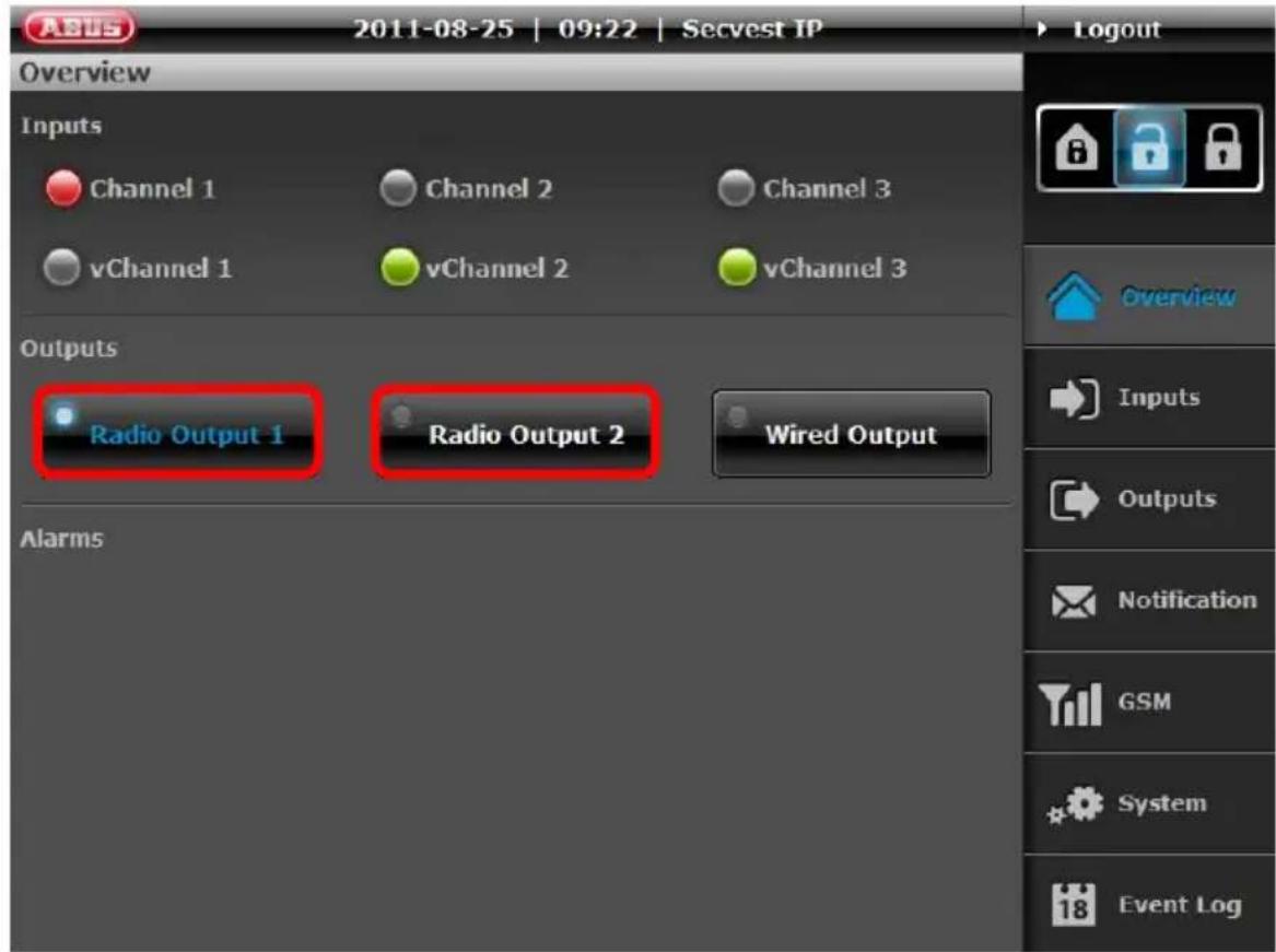
The socket gives an acoustic feedback on the success of the training process. Multiple sockets can be trained to one output.
When you are finished, press ESC/DEL once. Pressing any other buttons has no effect on the alarm centre at this point. The fifth LED lights up again permanently. The main menu is accessed again.
To exit programming mode, press ESC/DEL until the alarm centre starts to beep (about once per second). Close the housing or press and hold down the cover tamper contact (SW4 (B), underneath ESC/DEL) for about 4 seconds until it beeps twice. The data is saved in an EEPROM.
15.6 Menu 6 – Not in use
Option: Switching the display
(supervision monitoring displayed on LEDs: yes/no)
15.7 Menu 7 – External siren behaviour
In this menu, the type of signal from the external siren can be defined.
Press SELECT until the seventh LED from the bottom lights up.
Press the SET button once to go to menu 7.
The central alarm beeps briefly and LED 7 can show the following statuses:
| OFF | The external siren does not have a signalling and alarm functionNote: in this case, CON 3 does not have a function. | |
| ON permanent External | siren function is activated, without any acknowledgement flash or sound | |
| Flashing 1 | Hz External | siren function is activated, with acknowledgement flash and no sound |
| Flashing 5 | Hz External | siren function is activated, with acknowledgement flash and sound |
If you want to change the status, press SET repeatedly until you reach the required mode.
To exit programming mode, press ESC/DEL until the alarm centre starts to beep (about once per second). Close the housing or press and hold down the cover tamper contact (SW4 (B), underneath ESC/DEL) for about 4 seconds until it beeps twice. The data is saved in an EEPROM.
15.8 Menu 8 – Setting the default factory settings
Press SELECT until the eighth LED from the bottom lights up.
Press SET once to access menu 8.
All blue LEDs start flashing. This signals that the wireless module is ready to reset itself to the factory settings.
Press and hold down the ESC/DEL button for about 4 seconds until the flashing stops and the alarm centre beeps twice. The factory settings are now restored.
The main menu is accessed again.
To exit programming mode, press ESC/DEL until the alarm centre starts to beep (about once per second). Close the housing or press and hold down the cover tamper contact (SW4, underneath ESC/DEL) for about 4 seconds until it beeps twice.
The data is saved in an EEPROM.
16. Alarm types and notification
| Alarm | Notification | Explanation |
| Burglary | User-defined e-mail/optional dialler control/event log/alarm display via web interface/APP | |
| Delayed | Global e-mail/optional dialler control (burglary)/event log/alarm display via web interface/APP (intrusion) | |
| Panic | User-defined e-mail/optional dialler control/event log/alarm display via web interface/APP | |
| Fire | User-defined e-mail/optional dialler control/event log/alarm display via web interface/APP | |
| Technical | User-defined e-mail/optional dialler control/event log/alarm display via web interface/APP | |
| Battery error | Global e-mail/event log/alarm display via web interface/APP | One or more detectors have a discharged battery |
| Power fail | Global e-mail/event log/alarm display via web interface/APP | If the battery voltage drops below 10.5V, this alarm triggers |
| System error | Global e-mail/event log/alarm display via web interface/APP | Jamming/supervision/tampering trigger this alarm |
| DSL monitoring | Optional dialler control/event log | If the network connection is interrupted, this alarm triggers |
Refer to the chapter on "Relay and transistor outputs" for the dialler control
Global: means that an e-mail is sent to all the listed e-mail addresses.
User-specific: means that an e-mail is specifically sent according to the rules and receiver alarms added. The text can also be defined by the user.
17. Resetting an alarm

The control panel is activated and an alarm was triggered:
• Via the web server:
Press the "Deactivate" button.
• Via a wireless remote control:
Press the "Deactivate" button on your remote control to reset an existing alarm.


The control panel is not activated and an alarm was triggered:
• Via the web server:
Press the alarm button to reset the existing alarm.

• Via a wireless remote control:
In order to reset an alarm using a wireless remote control, the system must be armed and then disarmed:
(1) "Activate" button:
- If the detector is still in the triggered state, the alarm panel beeps eight times to signal that it cannot be armed.
○ If the detector is no longer in the triggered state, the alarm panel beeps twice and arms itself.
(2) "Deactivate" button: The existing alarm is reset and the control panel is in the disarmed state.
(3) All alarms are reset.

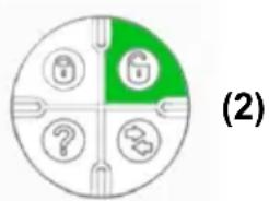

After an alarm is issued, we recommend that you check the status of the control panel on the web server or in the Secvest IP app.
18. Maximum system extension

flowchart
graph TD
    A["TV/41550"] --> B["WiFi"]
    B --> C["LAN / WLAN"]
    C --> D["WWW"]
    D --> E["E-Mail"]
    D --> F["E-Mail"]
    D --> G["SIP / VoIP"]
    D --> H["SIP APP"]
    D --> I["Phone"]
    D --> J["Phone"]
    D --> K["Phone"]
    D --> L["Phone"]
    D --> M["Phone"]
    D --> N["Phone"]
    D --> O["Phone"]
    D --> P["Casa10010"]
    D --> Q["FUSB30, FUB41, FUB42"]
    D --> R["FUSB340"]
    D --> S["FUSB320, FUB321, FUB321"]
    D --> T["FUSB350, FUB360"]
    D --> U["FUSB320, FUB321, FUB325"]
    D --> V["FUSB330, FUB370"]
    D --> W["FUSB410, FUB411, FUB412"]
    D --> X["FUSB403"]
    A --> Y["AZ6301, AZ0302"]
    Y --> Z["FUSB240"]
    Z --> AA["FUSB220"]
    AA --> AB["FUSB230"]
    AB --> AC["FUSB200"]
    AC --> AD["SDD"]
    AD --> AE["LAN / 868 MHz"]
    AE --> AF["FUSB97-B, FU5900-FU5981, FU5983-FU5990"]
    AE --> AG["FUSB100, FU8150"]
    AE --> AH["FUSB130, FU8140"]
    AE --> AI["FUSB410, FU8411, FU8412"]
    AE --> AJ["FUSB340, FU8350, FU8360"]
| System | Maximum number | |
| Version 1 Version 1 | ||
| 3x virtual zones 3x PIR | IP network cameras | 1x IP alarm module + 1x PIR IP network camera |
| 3x wireless zones 3 zo | ones with a total of 11 detectors (4/3/4 detectors per zone) | 3 zones with a total of 10 detectors (3/3/4 detectors per zone) + 1x external siren |
| 2x wireless outputs For any number of wireless sockets per output | ||
| 1x relay output To control wired components | ||
| 4x transistor outputs To trigger diallers | ||
| Operating units Max. 3 parts, wireless remote operation, Secvest key or additional door lock (any combination possible) | |
| Internal sirens Any number |
19. Firmware display of wireless PCB
When the alarm centre is connected to the power supply, a start routine is run through the centre. First of all, LEDs light up briefly and then the firmware status of the PCB is issued via dual coding.
Firmware of wireless PCB
| First display Second display | Firmware | status |
| LED in first place from the bottom lights up briefly | LED in fourth place from the bottom lights up briefly | 1.8 |
| LED in second place from the bottom lights up briefly | LED in second place from the bottom lights up briefly | 2.2 |

You can easily see the software status of the IP PCB via the web server.
“System → Maintenance → Firmware version”
20. Information on additional ABUS products
You can deal with any problems concerning the wireless range by using the repeater function of the Secvest 2WAY wireless universal module (FU8210). Read the user manual for the universal module.
21. Notes on maintenance
Set the alarm centre to learn mode when carrying out maintenance. You can then open the alarm centre or teach wireless components (or change the battery) without triggering a tamper alarm.
This is made using the web server: "System → Maintenance → Learn Mode → ON"
22. Technical data
| Dimensions (W x H x D) 193 x 233 x 45 mm | |
| Communication / alarming Email, | VoIP (landline, mobile, VoIP client) and push notification |
| Number of operating elements 3 | |
| Number of users 2 | |
| Number of remote controls 3 | |
| Number of wireless zones 3 | |
| Number of virtual IP zones 3 | |
| Display Status LEDs | |
| Outputs 1 x relay, 4 x transistors | |
| Wireless alarm bandwidth Narrow band | |
| Battery type 12 V / 1.2 Ah | |
| Operation Via Secvest key, wireless remote control, wireless additional door lock | |
| Gross weight 2,560 g | |
| DSL monitoring | Yes |
| Event log | 500 |
| Expandable (wireless) | Yes (by 8 detectors with IP alarm module) |
| Remote maintenance | Yes |
| Wireless frequency | 868.66 MHz |
| Wireless output | 10 mW |
| Housing material | ABS |
| Integrated siren | No |
| Power consumption | 13.8 W |
| Operating temperature | 0^ - 55^ C |
| Max. humidity | 75 % (non-condensing) |
| Max. transmission range | 100 m (outdoors) / 30 m (indoors) |
| Max. reception range | 100 m (outdoors) / 30 m (indoors) |
| Max. runtime under emergency power | 5 hours |
| Modulation | FM |
| Installation location | With optimally adjusted surrounding conditions for wireless performance |
| Net weight | 760 g |
| Network protocols | TCP/IP, DHCP, SMTP, DNS, NTP, HTTP |
| Network connection | RJ-45 Ethernet 10/100 Base-T |
| Backup power supply Yes | |
| Programming Via integrated web server | |
| Tamper monitoring Yes | |
| Switching outputs 5 | |
| Protection class IP34 | |
| Backup Reverse polarity protection | |
| Power supply DC 13.8 V | |
| Power supply monitoring Yes | |
| Language on the OSD DE, UK, FR, NL, DK | |
| Language of instructions DE, UK, FR, NL, DK, IT | |
| Power consumption 1,200 mA | |
| Environment class II | |
| Supported browsers Safari 5, Mozilla Firefox 5, Google Chrome, Internet Explorer 9 | |
| Encryption Yes | |
| Access protection User name, password | |
23. Customer service and support
End consumer:
Please consult your dealer or installer if you have any questions.
Dealers/installers:
Consult our website for product support information: www.abus-sc.com
24. Explanation of terms
√ Jamming: Interference of the wireless frequency.
√ Supervision: The availability of the detectors is monitored (i.e. is there a wireless connection: yes/no).
√ Tamper: For Tamper, the tamper contact is described which protects the housing and lid of the alarm centre from unauthorised removal.
√ SIP: The Session Initiation Protocol (SIP) is a network protocol for setting up, controlling and dismantling a communication session between two or more subscribers. SIP is a protocol commonly used in IP telephony.
√ Push notifications ... are messages you receive, even if the program on the Smartphone is not running. The user receives programs / apps which appear as messages like short text messages on the display. To receive a push notification, you need an internet connection (WLAN, UMTS,...).
√ LAN: Local Area Network
- Direct connection of the Secvest IP alarm centre to a PC → Cross-over cable (certain lines are swapped).
- Connection of the Secvest IP alarm centre through a switch → Patch cable required (all wires looped 1:1).
√ APP: Application
→ Usually a small program on modern mobile phones (e.g. iPhone).
√ NO: Normally Open (the detector contact is open when idle and triggers as soon as the circuit is closed).
√ NC: Normally Closed (the detector contact is closed when idle and open when activated).


- Contents
- Preface
- Disclaimer:
- Conformity
- Meaning of the symbols
- Important safety information
- Intended use
- General
- Warning
- Power supply
- Overloading/overvoltage
- Cables
- Installation location/operating environment
- Ensure the following:
- Care and maintenance
- Accessories
- Putting into operation
- Children and the device
- Scope of delivery
- Compatibility with ABUS products
- Installation
- Key:
- Installation procedure:
- Installation of the backup battery (backup power supply)
- Display and setting elements
- Display LEDs
- LED table
- Acoustic signal
- Setting elements on the wireless PCB
- Programming keys (A)
- Tamper switch
- CON1
- CON2
- DIP switch SW6
- CON3:
- Setting elements and connections on the IP board
- Restoring the factory settings
- IP board:
- Wireless board:
- Relay and transistor outputs
- Labelling the Secvest IP
- Putting into operation
- Enclosed software
- Configuration of the web server
- Login
- Overview
- Inputs:
- Creating/displaying/downloading live snapshots from PIR network cameras
- Bypass a channel via the Overview Menu
- Outputs:
- Alarms:
- Web server acoustic signalling
- Inputs
- RF-Inputs
- Event (zone attribute):
- Virtual Inputs (vChannel)
- Sensor:
- Outputs
- Scheduler
- Scheduler 1-2 configuration:
- Application examples:
- Assign Scheduler 1-2:
- Assing scheduler 3-6:
- Notification
- E-Mail Account
- Messages
- Recipients
- Setting up an SIP account
- Option: SIP to SIP telephony (free of charge)
- Option: SIP to PSTN telephony (subject to a charge)
- Email Rules
- SIP Account
- SIP Rules
- Example – complete call list (redialling):
- Example – recipient A responds to the second round and deactivates the alarm:
- Activating / deactivating the alarm centre / Internal activation
- GSM
- System
- Network
- Date & Time
- User Account
- Language
- Maintenance (training mode / firmware update)
- Firmware updates
- Factory Settings
- Restart
- Learn Mode
- Push Notification
- Setting up the push pairing process between the app and control panel
- Adding a new control panel:
- The control panel has already been added to the app:
- Important information about the receipt of push notifications:
- SD Card
- Event Log
- Logout
- Teaching the wireless components
- Menu 1 – Training the components
- Menu 2 – Deleting the components
- Menu 3 – Selecting the channel settings (channel mode)
- Explanation:
- Menu 4 – Displaying the signal strength
- Menu 5 – Controlling the wireless indoor siren, wireless info module and wireless socket
- Wireless indoor siren and wireless info module:
- Secvest wireless socket
- Socket training mode:
- Configuring the output via web server:
- Menu 6 – Not in use
- Menu 7 – External siren behaviour
- Menu 8 – Setting the default factory settings
- Alarm types and notification
- Resetting an alarm
- Maximum system extension
- Firmware display of wireless PCB
- Information on additional ABUS products
- Notes on maintenance
- Technical data
- Customer service and support
- Explanation of terms
Brand : ABUS
Model : FUAA10011
Category : Security System