
FU5929 - Security System ABUS - Free user manual and instructions
Find the device manual for free FU5929 ABUS in PDF.


| Product Type | Electronic security system |
| Brand | ABUS |
| Model | FU5929 |
| Dimensions | 150 x 75 x 30 mm |
| Weight | 500 g |
| Power Supply | 4 AA 1.5 V batteries |
| Battery Life | Approximately 1 year |
| Main Functions | Automatic locking, integrated alarm, intrusion attempt detection |
| Material | Tempered steel |
| Color | Black |
| Security Level | Grade 3 |
| Usage | Interior doors, safes, cabinets |
| Protection Rating | IP44 |
| Operating Temperature | -10 °C to 60 °C |
| Installation | Included screw fixing, drilling required |
| Maintenance | Clean with a soft dry cloth |
| Warranty | 2 years |
| Package Contents | Locks, screws, installation manual, batteries |
| Repairability | Spare parts available on request |
Frequently Asked Questions - FU5929 ABUS
User questions about FU5929 ABUS
0 question about this device. Answer the ones you know or ask your own.
Ask a new question about this device
Download the instructions for your Security System in PDF format for free! Find your manual FU5929 - ABUS and take your electronic device back in hand. On this page are published all the documents necessary for the use of your device. FU5929 by ABUS.
USER MANUAL FU5929 ABUS
natural_image
Close-up of a cylindrical mechanical component with a gray and metallic body, no visible text or symbols.FU59XX
Secvest Key 2WAY Wireless Cylinder Installation and Operating Instructions

Security Tech Germany

To guarantee a proper operation you will need a Secvest 2WAY with core software 5.04.25 or higher and RF software 5.14.
natural_image
Technical illustration of a mechanical device with a cylindrical component and mounting bracket (no text or symbols)Bedienung
Funk: 868,6625 MHz, narrow band
Leistung: 10mW
Many thanks for your purchase of this wireless activation cylinder. In choosing our product, you now have a piece of equipment that is built according to state-of-the-art technology. This product complies with current domestic and European regulations. Conformity has been proven, and all related certifications are available from the manufacturer on request. To maintain this status and to guarantee safe operation, it is your obligation to observe these operating instructions! In the event of questions, please contact your local specialist dealer. The wireless activation cylinder is used for activating and deactivating alarm systems.

Observe the notes and instructions in this guide! If you do not follow these instructions, your guarantee claim becomes invalid! No liability can be accepted for resulting damages! The electronic part of the product must not be changed or modified in any way.
Installation
- The wireless cylinder has been produced according to DIN 18252 and is suitable for use in DIN-approved mortise locks. Please note: Self-assembly may not be possible on safety doors!
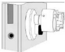
- Remove the old cylinder. To do this, open the door and unscrew the fixing screw (see fig. 1). Completely remove the fixing screw.
- Insert a key into the old cylinder and turn the cam with the key so that you can remove the cylinder. The cam prevents the cylinder from being removed when in the normal cylinder position.
- Insert the wireless cylinder so that the knob is on the inner side of the door. The cam position must be set accordingly here by turning the knob. If the cylinder becomes jammed in the hole, then the hole or cylinder clamps need to be reworked. Never use a hammer to force the cylinder into the hole.
- Fasten the wireless cylinder using the fixing screw and check that it locks properly.
Programming
Remove the grip cover from the wireless cylinder by completely unscrewing both hexagon socket screws and then carefully pulling off the cover (caution: the grip cover is connected to the cylinder by a short cable).
Set the DIP switch or switches according to your requirements.
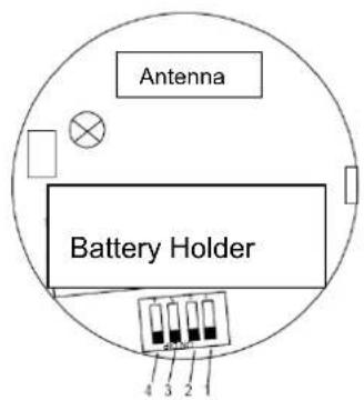
Settings on the DIP switch
| Switch | Position | Meaning |
| 1 | ON | Reserved |
| 2 | ON | Tones without transmission signal |
| OFF | Tones with transmission signal | |
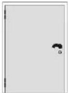
| 3 | ON | Left door hinge (DIN) |
| OFF | Right door hinge (DIN) | |
| 4 | ON/OFF | Not used |
Explanation of DIN left/right and installation
DIN right
DIN left
Installation of wireless cylinder

natural_image
Technical illustration of a mechanical device with a cylindrical component and mounting bracket (no text or symbols)Operation
Training in Secvest
Setup Mode → Other Devices → Secvest Key → Add/Remove Key
Select a Key (Key1, Key2, Key3 or Key4). "Please insert battery" then appears in the display.
Insert the battery. The Secvest Key sends a training signal to the alarm centre. After the Secvest Key has been trained successfully, a symbol appears next to the selected device.
Assigning the partitions
Setup Mode → Other Devices → Secvest Key → Edit Key
Select the trained Secvest Key (Key1, Key2, Key3 or Key4). You can then define the partitions that should be switched by the Secvest Key.
Testing
Setup Mode → Test → Secvest Key
Select the trained Secvest Key (Key1, Key2, Key3 or Key4).
The Secvest Key functions and correct positioning of DIP switch 3 to the door hinge can be tested here.
"Unlocked" is shown when the door is unlocked.
"Locked" is shown when the button is pressed and the door is then locked.
The received signal strength is also shown.
Operation
Meaning of the tones:
Beep After pressing a button and after transmission (DIP 2 = OFF)
Double beep System is activated
Long beep System is deactivated and after pressing the Timeout (30 s) button
8 beeps "System cannot be activated" (zone open) and no feedback received
Activating the alarm system:
Press the button (a beep tone is heard). You can then lock the door once or twice within the following 30 seconds. The Secvest Key sends the activation signal to the alarm centre.
The alarm system is now activated.
Deactivating the alarm system:
Unlock the door. The Secvest Key then immediately sends a deactivation signal to the alarm centre. The alarm system is now deactivated.
User scenarios
Press button, lock once => Centre activated
Unlock once => Centre deactivated
Press button, lock twice => Centre activated
Unlock twice => Centre deactivated
Door only closed, not locked => Centre activated elsewhere
Pull back latch to open door => Centre deactivated
Lock once => Centre activated elsewhere
Unlock => Centre deactivated
Lock twice => Centre activated elsewhere
Unlock => Centre deactivated
Button not pressed, lock once => Centre not activated
Button not pressed, lock twice => Centre not activated
Calibration
When it is delivered, the knob is calibrated so that the user scenarios listed above can be carried out. If these do not work (for example if the cylinder is installed upside-down), you can recalibrate the knob after mounting it. This requires the following actions:
- Mount the cylinder on the door.
- Press the button on the cap of the knob for 20 seconds until you hear three beeps.
- Then lock the cylinder again and pull out the key.
- After a two-second continuous tone, the cylinder is recalibrated.
Note: Calibration has no effect on the cylinder's direction of rotation. This is defined using DIP switch 3.
Technical data
Power supply: 3 V lithium battery
Battery type: CR2
Service life: Approx. 12 months
Temperature range: -10 °C to +55 °C
Environment class: 2
Wireless transmission: 868.6625 MHz narrow band
Power: 10
mW
Everything possible has been done to ensure that the contents of these instructions are correct. However, neither the author nor ABUS Security-Center GmbH & Co. KG can be held liable for loss or damages caused directly or indirectly by these instructions, whether real or alleged. We reserve the right to make changes to these instructions without prior notice.
This product complies with the requirements of the EC directive: 1995/5/EC “Directive on radio and telecommunications terminal equipment and the mutual recognition of their conformity”.
The declaration of conformity can be ordered from:
info@abus-sc.com © ABUS Security-Center GmbH & Co. KG, July 2009
Préface
Chère cliente, cher client,
natural_image
Two identical rectangular panels with small black icons labeled Q and D, no text or symbols present.
natural_image
Technical line drawing of a mechanical device with a cylindrical component and mounting bracket (no text or symbols)Utilisation
natural_image
Technical line drawing of a mechanical assembly with no visible text or symbolsBediening
Inleren in de Secvest
natural_image
Technical illustration of a mechanical device with a cylindrical component and mounting bracket (no text or symbols)Utilizzo
natural_image
Technical illustration of a mechanical device with a cylindrical component and mounting bracket (no text or symbols)Betjening
Indstilling i Secvest


- Bedienung
- Installation
- Programming
- Explanation of DIN left/right and installation
- Operation
- Training in Secvest
- Assigning the partitions
- Testing
- Meaning of the tones:
- Activating the alarm system:
- Deactivating the alarm system:
- User scenarios
- Calibration
- Technical data
- Préface
- Utilisation
- Bediening
- Inleren in de Secvest
- Utilizzo
- Betjening
- Indstilling i Secvest
Brand : ABUS
Model : FU5929
Category : Security System