HKC 55 5 2 EBIPlusSCA - Saw FESTOOL - Free user manual and instructions
Find the device manual for free HKC 55 5 2 EBIPlusSCA FESTOOL in PDF.

| Product type | Cordless hand-held circular saw |
| Brand | Festool |
| Model | HKC 55 5 2 EBIPlusSCA |
| Category | Saw |
| Motor voltage | 14.4 - 18 V |
| No-load speed | 4500 rpm |
| Blade diameter | 160 mm |
| Cutting depth at 0° | 0 - 55 mm |
| Cutting depth at 50° | 38 mm |
| Cutting angle range | 0° to 50° |
| Weight without battery | 3.4 kg |
| Power supply | Festool BP 18 Li battery (3.1 / 5.2 / 6.2 Ah) |
| Electrodynamic brake | Yes, stops within 2 seconds |
| Soft start | Yes |
| Restart protection | Yes |
| Pivoting guard | Yes, with return lever |
| Dust extraction connection | Diameter 27/32/36 mm |
| Plunge function | Yes, with lever |
| Maintenance | Regular cleaning of ventilation slots and the guard |
| Spare parts | Genuine Festool parts only |
| Repairability | Festool authorized service center |
| Integrated Bluetooth® | Yes, with compatible batteries (ASI) |
| Data chip | Yes, automatic tool data recording |
Frequently Asked Questions - HKC 55 5 2 EBIPlusSCA FESTOOL
User questions about HKC 55 5 2 EBIPlusSCA FESTOOL
0 question about this device. Answer the ones you know or ask your own.
Ask a new question about this device
Download the instructions for your Saw in PDF format for free! Find your manual HKC 55 5 2 EBIPlusSCA - FESTOOL and take your electronic device back in hand. On this page are published all the documents necessary for the use of your device. HKC 55 5 2 EBIPlusSCA by FESTOOL.
USER MANUAL HKC 55 5 2 EBIPlusSCA FESTOOL
Head of Product Development
Ralf Brandt
Head of Product Conformity
valid in combination with battery pack/
valid in combination with Bluetooth® battery pack/
1 Symbols. 19
2 Safety warnings. 19
3 Intended use 22
4 Technical data. 22
5 Parts of the device. 22
6 Battery pack. 23
7 Settings. 23
8 Working with the electric power tool.....25
9 Service and maintenance. 26
10 Accessories 26
11 Environment. 27
12 General information. 27
1 Symbols

Warning of general danger

Warning of electric shock

Read the operating instructions and safety instructions.

Wear ear protection.

Wear protective gloves when changing tools and working with raw materials.

Wear a dust mask.

Wear protective goggles.

Do not dispose of it with domestic waste.

Direction of rotation of saw and the saw blade

Electro-dynamic run-down brake

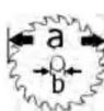
Saw blade dimensions
a = diameter
b ... Locating bore

Tool contains a chip which stores data. See section 12.1

CE marking: Confirms the conformity of the power tool with the European Community directives.

Tip or advice

Handling instruction

Removing the battery pack.

Inserting the battery pack.

Risk of pinching fingers and hands!

Danger area! Keep hands away!
2 Safety warnings
2.1 General power tool safety warnings

WARNING! Read all safety warnings, instructions, illustrations and specifica-
tions provided with this power tool. Failure to follow all instructions listed below may result in electric shock, fire and/or serious injury.
Save all warnings and instructions for future reference.
The term "power tool" in the warnings refers to your mains-operated (corded) power tool or battery-operated (cordless) power tool.
Follow the operating manual for the charger and the battery pack.
2.2 Safety instructions for specific circular saws
Cutting procedures

DANGER: Keep hands away from the area and the blade. Keep your second and auxiliary handle, or motor ng. If both hands are holding the saw, cannot be cut by the blade.
- Do not reach underneath the workpiece.
The guard cannot protect you from the blade below the workpiece. - Adjust the cutting depth to the thickness of the workpiece. Less than a full tooth of the blade teeth should be visible below the workpiece.
- Never hold the workpiece in your hands or across your leg while cutting. Secure the workpiece to a stable platform. It is important to support the work properly to minimise body exposure, blade binding, or loss of control.
- Hold the power tool by insulated gripping surfaces, when performing an operation where the cutting tool may contact hidden wiring. Contact with a "live" wire will also make exposed metal parts of the power
English
tool "live" and could give the operator an electric shock.
- When ripping, always use a rip fence or straight edge guide. This improves the accuracy of cut and reduces the chance of blade binding.
- Always use blades with correct size and shape (diamond versus round) of arbour holes. Blades that do not match the mounting hardware of the saw will run off-centre, causing loss of control.
- Never use damaged or incorrect blade washers or bolt. The blade washers and bolt were specially designed for your saw, for optimum performance and safety of operation.
Causes of kickbacks and corresponding safety instructions
- kickback is a sudden reaction to a pinched, jammed or misaligned saw blade, causing an uncontrolled saw to lift up and out of the workpiece toward the operator;
- when the blade is pinched or jammed tightly by the kerf closing down, the blade stalls and the motor reaction drives the unit rapidly back toward the operator;
- if the blade becomes twisted or misaligned in the cut, the teeth at the back edge of the blade can dig into the top surface of the wood causing the blade to climb out of the kerf and jump back toward the operator.
Kickback is the result of saw misuse and/or incorrect operating procedures or conditions and can be avoided by taking proper precautions as given below.
- Maintain a firm grip with both hands on the saw and position your arms to resist kickback forces. Position your body to either side of the blade, but not in line with the blade. Kickback could cause the saw to jump backwards, but kickback forces can be controlled by the operator, if proper precautions are taken.
-
When blade is binding, or when interrupting a cut for any reason, release the trigger and hold the saw motionless in the material until the blade comes to a complete stop. Never attempt to remove the saw from the work or pull the saw backward while the blade is in motion or kickback may occur. Investigate and take corrective actions to eliminate the cause of blade binding.
-
When restarting a saw in the workpiece, centre the saw blade in the kerf so that the saw teeth are not engaged into the material. If a saw blade binds, it may walk up or kickback from the workpiece as the saw is restarted.
- Support large panels to minimise the risk of blade pinching and kickback. Large panels tend to sag under their own weight. Supports must be placed under the panel on both sides, near the line of cut and near the edge of the panel.
- Do not use dull or damaged blades. Unsharpened or improperly set blades produce narrow kerf causing excessive friction, blade binding and kickback.
- Blade depth and bevel adjusting locking levers must be tight and secure before making the cut. If blade adjustment shifts while cutting, it may cause binding and kickback.
- Use extra caution when sawing into existing walls or other blind areas. The protruding blade may cut objects that can cause kickback.
Lower guard function
a. Check the lower guard for proper closing before each use. Do not operate the saw if the lower guard does not move freely and close instantly. Never clamp or tie the lower guard into the open position. If the saw is accidentally dropped, the lower guard may be bent. Raise the lower guard with the retracting handle and make sure it moves freely and does not touch the blade or any other part, in all angles and depths of cut.
b. Check the operation of the lower guard spring. If the guard and the spring are not operating properly, they must be serviced before use. Lower guard may operate snug- gishly due to damaged parts, gummy de- posits, or a build-up of debris.
c. The lower guard may be retracted manually only for special cuts such as "plunge cuts" and "compound cuts". Raise the lower guard by the retracting handle and as soon as the blade enters the material, the lower guard must be released. For all other sawing, the lower guard should operate automatically.
d. Always observe that the lower guard is covering the blade before placing the saw down on bench or floor. An unprotected, coasting blade will cause the saw to walk
backwards, cutting whatever is in its path. Be aware of the time it takes for the blade to stop after switch is released.
Function of the guide wedge [1-5]
a. Use the correct saw blade for the guide wedge, where possible. The function of the guide wedge is restricted if using saw blades with a thicker blade core. To ensure that the guide wedge functions properly, make sure the blade core of the saw blade is thinner than the guide wedge and that the tooth width is greater than the thickness of the guide wedge. Expect increased risk of kickback when using a thicker saw blade.
b. Do not operate the saw if the guide wedge is bent. Even the slightest problem can cause the guard to close more slowly.
Further safety instructions
- This electric power tool cannot be installed in a work bench. The electric power tool may become unsafe and cause serious accidents if installed in benches from other manufacturers or self-manufactured work benches.
- Never place your hands into the chip ejector. You may injure yourself on rotating parts.
- Use suitable detectors to determine if utility lines are hidden in the work area or call the local utility company for assistance. Acontact with electric lines can lead to fire and electric shock. Damaging a gas line can lead to explosion. Penetrating a water line causes property damage or may cause an electric shock.
- Wait until the power tool stops completely until placing it down. The tool can become entangled and lead to a loss of control of the power tool.
- Do not use the machine for overhead work.
- Harmful/toxic dust may be produced during your work (e.g. paint containing lead, certain types of wood and metal). Inhaling or coming into contact with this dust may represent a hazard for operating personnel or persons in the vicinity. Comply with the safety regulations that apply in your country.

Wear a P2 dust mask to protect your
health.
Ensure that enclosed spaces are adequately ventilated and, if necessary, connect a mobile dust extractor.


Wear suitable personal protective equipment: Ear protection, protective goggles, dust mask for work that generates dust, protective gloves for working with rough materials and for changing tools.
- Harmful/toxic dust may be produced during your work (e.g. paint containing lead, certain types of wood or metals). Contact with or inhalation of this dust may pose a risk for the operating personnel or persons in the vicinity. Comply with the safety regulations that apply in your country.
- Check whether there are any signs of damage to the housing components, such as cracks or stress whitening. Have any damaged components repaired before using the power tool.
- Do not use power supply units or third-party battery packs to operate cordless power tools. Do not use third-party chargers to charge the battery packs. The use of accessories not expressly authorised by the manufacturer can result in electric shocks and/or serious accidents.
2.3 Residual risks
In spite of compliance with all relevant design regulations, hazzards while operating the machine still occur e.g.:
- Touching the saw blade in the area of the front opening below the saw table,
- Touching the parts of the saw blade that protrude below the saw table while cutting,
- Touching rotating parts from left and right sides: saw blade, clamping flange, flange screw.,
- Kickback of machine due to jamming in the workpiece,
- Touching live parts when the casing is opened and the mains plug is in the socket,
- the flying off of parts,
- the flying off of machine parts from a damaged machine,
- noise emission,
-dust emission.
2.4 Sawing aluminium
When sawing aluminium, the following measures must be taken for safety reasons:

- We are protective goggles.
- Connect the power tool to a suitable dust extractor with an antistatic suction hose.
- Regularly clean dust deposits from the motor housing on the power tool.
- Use an aluminium saw blade.
- When sawing panels, they must be lubricated with petroleum, but thin-walled profiles (up to 3mm ) can be sawed without lubrication.
2.5 Emission levels
The levels determined in accordance with EN 62841 are typically:
Sound pressure level L
$$ \mathrm {p} _ {\mathrm {A}} = 9 6 \mathrm {d B} (\mathrm {A}) $$
Sound power level L
$$ \mathrm {w} _ {\mathrm {A}} = 1 0 7 \mathrm {d B} (\mathrm {A}) $$
Uncertainty K = 4
dB


CAUTION
Noise generated when working Risk of damage to hearing
Use ear protection.
Vibration emission level a_h (vector sum for three directions) and uncertainty K measured in accordance with EN 62841:
Sawing wood
$$ a _ {h} \leqslant 2. 5 m / s ^ {2} $$
$$ K = 1. 5 \mathrm {m} / \mathrm {s} ^ {2} $$
Sawing aluminium
$$ a _ {h} \leqslant 2. 5 m / s ^ {2} $$
$$ K = 1. 5 \mathrm {m} / \mathrm {s} ^ {2} $$
The specified emission levels (vibration, noise)
- are used to compare machines.
- They are also used for making preliminary estimates regarding vibration and noise load during operation.
- They represent the primary applications of the power tool.

CAUTION
The emission values may deviate from the specified values. This is dependent on how the tool is used and the type of workpiece being machined.
The actual load during the entire operating cycle must be evaluated.
Depending on the actual load, suitable protective measures must be defined in order to protect the operator.
3 Intended use
Portable circular saw designed for sawing
- wooden materials and wood-based materials,
plaster and cement compound fibres, - plastic materials,
- aluminium (only with a special saw blade for aluminium offered by Festool)
Only use saw blades with the following dimensions:
- Saw blades in accordance with EN 847-1
- Saw blade diameter 160 mm
- Recommended cutting width 1.8 ~mm , max. 2.2 mm with restricted function of the guide wedge
- Location hole 20 mm
- Recommended standard blade thickness 1.2 mm, range of 1.1 to max. 1.25 mm possible
- Suitable for speeds of up to 9500 rpm Do not use cutting or sanding discs.
Only saw materials for which the saw blade in question has been designed.
This power tool may only be used by experts or instructed persons.

The user is liable for improper or non-intended use.
This power tool is suitable for use with BP Festool battery packs of the same voltage class.
4 Technical data
Cordless circular saw HKC 55 EB
Motor voltage 14.4-18 V
Speed (no-load) 4500 rpm
Inclination 0^ to 50^
Cutting depth at 0^ 0 - 55 ~mm
Cutting depth at 50^38mm
Saw blade dimensions
recommended 160 × 1.8 × 20 ~mm
max. 160 × 2.2 × 20 ~mm
Weight excl. battery pack 3.4 ~kg
5 Parts of the device
[1-1] Handles
[1-2] Switch-on lock
[1-3] Lever for changing blades
[1-4] Retractor lever for pendulum guard
[1-5] Guide wedge
[1-6] Pendulum guard
[1-7] On/Off switch
[1-8] Lever for plunge function
[1-9] Split scale for cutting depth stop (with/without guide rail)
[1-10] Extractor connector
[1-11] Angle scale
[1-12] Knob for angle setting
[1-13] Cutting depth adjuster
[1-14] Capacity display button on battery pack
[1-15] Capacity display
[1-16] Battery pack
[1-17] Button for releasing the battery pack
[1-18] Adjustable jaws
The specified illustrations appear at the beginning of the Operating Instructions.
Accessories shown or described are not always included in the scope of delivery.
6 Battery pack
Before using the battery pack, check that the battery interface is clean. Any contamination of the battery interface may impair correct contact and lead to the contacts being damaged.
A faulty contact may result in the machine overheating or being damaged.
[2A]
[2B]

Remove the battery pack.
Insert the battery pack – until it clicks into place.
Further information about the charger and battery pack with capacity indicator can be found in the corresponding operating manual.
7 Settings

WARNING
Risk of injury, electric shock
Always disconnect the battery packs from the machine before performing any type of work on the machine!
7.1 Electronics
Smooth start-up
The electronically controlled smooth start-up ensures that the machine starts up jolt-free.
Constant speed
The motor speed remains constant through electronic control to ensure a uniform cutting speed even when under load.
Current limiting
Current limiting prevents excessive current consumption under extreme overload, which can lead to a decrease in the motor speed. The motor immediately restarts after the load is removed.
Brake
The HKC 55 EB is fitted with an electronic brake. When the saw is switched off, the saw blade slows to a stop electronically within approx. 2 seconds.
Restart protection
The integral restart protection prevents the electric power tool from automatically starting up again after an interruption in power when the ON/OFF switch is pressed. In this case the electric power tool must be switched off and then switched back on again.
Temperature cut-out
When exceeding a certain engine temperature level, the machine power supply and speed are capped. The power tool continues operating at reduced power to allow the ventilator to cool the motor rapidly. The power tool resumes to full performance automatically once the motor has cooled sufficiently.
7.2 Adjusting the cutting depth
The cutting depth can be set at 0 - 55 mm.
Press cutting depth adjustment [3-1].
- Pull up or push down saw at main handle.

Cutting depth without guide rail/track rail
max. 55mm

Cutting depth with guide rail/track rail max. 51 mm
7.3 Adjusting the cutting angle
The saw table must be on an even surface when adjusting the cutting angle.
Between 0^ and 50^ :
- Open the rotary knob [4-2].
- Swivel the saw unit to the required cutting angle [4-1].
Close the rotary knob [4-2].
Both adjustments (0^ and 50^) are set at the factory and can be readjusted by the customer service team.
For angled cuts, the cutting depth is smaller than the value displayed on the cutting depth scale.
7.4 Adjust pendulum guard

CAUTION
Risk of injury! Sharp edges! The pendulum guard swings back quickly in the event of sudden release.
The pendulum guard [1-6] must only be opened with the retractor lever [1-4].
7.5 Selecting the saw blade
Festool saw blades are identified by a coloured ring. The colour of the ring represents the material for which the saw blade is suited.
WARNING! Risk of injury! Pendulum hood mechanism not working correctly! Diamond saw blades must not be used to saw cement-bonded fibreboard.
Colour Material Symbol
| Yellow Wood | ||
| Red Laminate, mineral ma- terial | HPL | HPL/TRESPA |
| Green Plaster- and cement- bonded chipboard and fibreboard | ||
| Blue Aluminium, plastic | AL |
7.6 Changing the saw blade

WARNING
Risk of injury
- Remove the battery pack from the power tool before performing any work on the power tool.


CAUTION
Risk of injury from hot and sharp insertion tool
- Do not use any blunt or faulty insertion tools.
Wear protective gloves when handling an insertion tool.
Removing the saw blade
- Swivel saw to 0^ position before replacing the saw blade and set maximum cutting depth.
Position saw on motor cover when replacing [5-1].
Turn the lever [5-4] as far as the stop. - Open the screw [5-8] using the Allen key [5-3].
- Hold the pendulum guard open [5-7] only with retractor lever [5-5].
- Remove the saw blade [5-9].
Inserting the saw blade
WARNING! Check the screws and flange for contamination and only use clean and undamaged parts.
Insert the new saw blade.
WARNING! The direction of rotation of the saw blade [5-10] and saw [5-6] must match. Serious injuries may occur in the event of non-compliance.
Insert the outer flange [5-11] so that the pin engages in the recess on the inner flange.
- Release retractor lever [5-5] and allow the pendulum guard [5-7] to swivel back to its final position.
- Tighten the screw [5-8].
Reposition the lever [5-4].
7.7 Dust extraction

WARNING
Health hazard posed by dust
Always work with an extractor.
Comply with national regulations.
- When sawing carcinogenic materials, always connect a suitable extraction mobile in accordance with national regulations. Do not use the chip collection bag.
Independent extraction
- Secure the connection piece [6-2] of the dust collection bag [6-3] at the extractor connector [6-1] with a clockwise rotation.
To empty, remove the connection piece of the dust collection bag from the extractor connector with an anti-clockwise rotation.
Festool mobile dust extractor
A Festool mobile dust extractor with a suction hose diameter of 27 / 32 ~mm or 36 ~mm (36 mm recommended due to the reduced risk of clogging) can be connected to the extractor connector [6-1].
The adapter on a 27 diameter suction hose is inserted into the angle adapter . The adapter on a 36 diameter suction hose is inserted over the angle adapter .
CAUTION! A static charge may build up if no antistatic suction hose is used. The user may receive an electric shock and the power tool's electronics may be damaged.
8 Working with the electric power tool

When working on the machine, observe all of the safety warnings that are listed
at the start as well as the following rules:
- Only guide the power tool towards the workpiece when it is switched on.
- Before each use, check that the pendulum guard is working correctly using the retractor lever [1-4]. Ensure that the pendulum guard can move freely and does not come into contact with the saw blade or other parts at any cutting angle or depth. Only use this power tool when it is in perfect working order.
- Always secure the workpiece in such a way that it cannot move during machining.
- Make sure that the extractor hose does not snag the entire saw cut, either on the work
piece, the workpiece support or hazards on the ground.
- When working, always hold the power tool with both hands on the handles [1-1]. This is a prerequisite for precise work and is essential for plunge-cutting. Plunge into the workpiece slowly and evenly.
- Always push the saw forwards [8-9], and never towards yourself.
- Adapt the infeed speed to prevent the cutters on the saw blade from overheating and prevent plastic materials from melting during cutting. The harder the material to be sawn, the lower the feed speed needs to be.
- Make sure that the rotary knob [1-12] is tightened before starting work.
- CAUTION! Risk of overheating. Before use, make sure that the battery pack is securely clicked into place
8.1 Switch on/off
▶ Slide switch-on lock [1-2] upwards.
Press the ON/OFF switch [1-7].
$$ \begin{array}{l} P r e s s = O N \ \text {R e l a s e} = 0 F F \ \end{array} $$
8.2 Acoustic warning signal
Acoustic warning signals sound and the power tool switches off in the following operating states:

Battery flat or power tool overloaded:
peep
Change the battery
Reducing the load on the power tool
8.3 Sawing along the scribe mark
The cut indicators display the cutting sequence without a guide rail:
$$ \begin{array}{l} 0 ^ {\circ} \text {c u t s : [ 7 - 1 ]} \ 4 5 ^ {\circ} \text {c u t s : [ 7 - 2 ]} \ \end{array} $$
8.4 Cutting sections
Position the saw with the front part of the saw table on the workpiece, switch on saw and push forward in cutting direction.
8.5 Sawing cut-outs (plunge cuts)

In order to avoid kickbacks, the following actions must always be followed when one cutting:
- Always position saw with the rear edge of the saw table against a fixed stop.
English
- When working with the guide rail, place the saw against the kickback stop FS-RSP (accessories) clamped to the guide rail.

Caution! Danger of crushing!
Always keep a firm grip on the machine with your free hand when adjusting plunge cuts. Never position your fingers behind or below the saw blade.
Procedure
Adjusting cutting depth, see section 7.2.
Press lever [8-1] down.
Sawing unit swivels upwards to plunge-cut position.
Hold retractor lever [8-2] downwards as far as stop.
Pendulum guard [8-4] opens and the saw blade is exposed.
Position saw on workpiece and position against a stop (kickback stop).
Switch on saw.
- Slowly press down saw to the set cutting depth until the saw engages, release retractor lever [8-2] and push forward in cutting direction [8-9].
The notch [8-3] indicates the absolute rear cutting point of the saw blade (diameter 160 mm) when using the saw at maximum cutting depth with the guide rail.
9 Service and maintenance

WARNING
Risk of injury, electric shock
Always remove the battery pack from the power tool before performing any maintenance or service work.
- All maintenance and repair work which requires the motor housing to be opened should always be carried out by an authorised service workshop.

Customer service and repairs must only be carried out by the manufacturer or service workshops. Find the nearest address at: www.festool.co.uk/service
Always use original Festool spare parts. Order no. at: www.festool.co.uk/service

Cleaning the machine regularly, especially the adjusting devices and guides, is
an important safety factor.
Observe the following instructions:
Damaged safety devices and parts, such as a faulty lever for changing tools [1-3], must be properly repaired or replaced in a recognised specialist workshop, unless otherwise indicated in the operating manual.
- To ensure constant air circulation, always keep the cooling air openings in the housing clean and free of blockages.
- Use an extractor on all openings in order to remove wood chips and splinters from the power tool. Never open the protective lid.
The pendulum guard must always be able to move freely and close independently. Always keep the area around the pendulum guard clean. Clear from dust and chippings by blowing out with compressed air or using a brush.
- Keep the contacts on the power tool, charger and battery pack clean.
- When working with plaster- and cement-bonded fibreboards, clean the tool particularly thoroughly. Clean the vents of the power tool and on/off switch using dry, oil-free compressed air. Otherwise, gypsum dust deposits may build up inside the power tool's housing and on the on/off switch and harden when exposed to humidity. This may impair the switching mechanism
10 Accessories
Refer to the Festool catalogue for the order numbers of accessories and tools or find them online at www.festool.co.uk.
In addition to the accessories described, Festool also provides a comprehensive range of system accessories that allow you to use your saw more effectively and in diverse applications, e.g.:
- Parallel stop, extension table PA-HKC 55
- Kickback stop FS-RSP
- Parallel stop FS-PA and guide extension FS-PA-VL
- Side-mounted cover, false joint ABSA-TS 55
10.1 Saw blades, other accessories
In order to saw different materials quickly and cleanly, Festool offers saw blades for all applications and these are specially designed for your Festool saw.
10.2 Guide rail
The guide rail enables you to make clean, accurate cuts while simultaneously protecting the surface of the workpiece from damage.
In conjunction with the extensive range of accessories, exact angled cuts, metre cuts and fitting work can be completed with the guide system. The option of attaching the guide rail securely using clamps [8-7] ensures safer working conditions.
- Adjust the guide play between the saw table and the guide rail using the two adjustable jaws [8-8].
Bed in the splinter guard before using the guide rail for the first time[8-5]:
Position saw with the entire guide plate at the rear end of the guide rail.
- Swivel saw to 0^ position and set maximum cutting depth.
Switch on saw.
Slowly drop the splinter guard across the entire length without setting down.
The edge of the splinter guard now corresponds exactly to the cutting edge.
Position the guide rail for sawing the splinter guard on a test piece of wood.
10.3 Cross cutting guide rail
The cross cutting guide rail is designed for sawing wood and panel materials.
It enables precise and clean cuts, in particular angled cuts can be performed simply and with repeat accuracy. The saw automatically moves back to the initial position after the sawing process.
Observe the instructions in the operating manual for the FSK cross cutting guide rail
11 Environment

Do not dispose of the device in the household waste! Recycle devices, accessories and packaging. Observe appli-national regulations.
EU only: In accordance with the European Directive on waste electrical and electronic equipment and implementation in national law, used power tools must be collected separately and handed in for environmentally friendly recycling.
Information on REACH: www.festool.com/reach
12 General information
Imported into the UK by
Festool UK Ltd
1 Anglo Saxon Way
Bury St Edmunds
IP30 9XH
Great Britain
12.1 Information on data privacy
The power tool contains a chip which automatically stores machine and operating data. The data saved cannot be traced back directly to an individual.
The data can be read in a contactless manner using special devices and shall only be used by Festool for fault diagnosis, repair and warranty processing and for quality improvement or enhancement of the power tool. The data shall not be used in any other way without the express consent of the customer.
12.2 Bluetooth®
The Bluetooth® word mark and the logos are registered trademarks of Bluetooth SIG, Inc.; they are used by TTS Tooltechnic Systems AG & Co. KG, and therefore by Festool, under licence.
Sommaire
Skaeredybdev 50^38mm
Savklingemål
Akku rundsav HKC 55 EB
anbefalet 160 × 1,8 × 20 ~mm
maks. 160 × 2,2 × 20 ~mm
$$ S l i p = s l u k $$
8.2 Akustiske advarselssignaler
He BbI6paCbIBaIe BMeCTe C 6bITOBbIMN OTXoIaMn.

HappaBJIeHne BpaIeHnI nnIbI nIINb-Horo DnCKa

3JIeKtpoDInH. INHepu. TOpMoXeHne
Pa3Mep nIbHOro dIscKa
a ...Диаметр
b ...посадочhoe OTBepctne

B inhctpymte yctaHOBlen qin dIy coxpanen daHHbIX. Cm. pa3deJ 12.1

MapknpoBka CE: PoiTBePjdaeT coOTBeTCTBnE 3JIeKToHnHcTpymEnTa OCHOBnblm Tpe6oBaHnM dIpeKtNb EC.

HctpyKu,peKoMeHdaun

HCTpyKcIy no nCNoJIb3OBAHnIO

OToeDInHeHne aKKymyIaTopa

YcTaHOBka aKKymyIaTopa

OpaHocTb 3aUeMJIeHnI paJIbUeB n KInCTe pyK!

Опасная зона! Дерхитepукн ha 6e3- onachompacctoHn!
2Уka3aHЯ NO TexHnKe 6e3oNaChOCTN
2.1 06ие yka3aHnno TeXnKe 6e3oNaChocTn ДЯ 3JIeKTPoINHcTpymeHTOB

Pa6oTaIeB3aUHTbIXHayuHnKax.
3HaueHne Bn6paun a, no TpE M OcA M (BeKTop-Ha cymma) n Ko3ΦuNHeNT NOrpeuHocTn K, onpeJeIeHHbIe no EN 62841:
Пи�нные древсаны
$$ a _ {h} \leqslant 2, 5 \mathrm {m} / \mathrm {c} ^ {2} $$
$$ K = 1, 5 \mathrm {m} / \mathrm {c} ^ {2} $$
Pe3aHne aJIOMnHnIa
$$ a _ {h} \leqslant 2, 5 m / c ^ {2} $$
$$ K = 1, 5 \mathrm {m} / \mathrm {c} ^ {2} $$
Pycckn
yKa3aHHbIe 3NaueHnYpOBnYuMa/Bn6paCnN
-cnyjkaTДЯсравениИнстpyMeHTOB;
-MoJHo TaKKe IcNoJIb3OBAtBДЯпpeiBapN-TeIbHOI OueHKn ⅢyMoBOI N Bv6paCIOHHOHarpy3KN Bo BpeMa pa60TbI;
- OtpaKaIO T OCHOBbIe 06JIaCTn IprIMHeHnA 3JIeKTpOuHcTpyMeHTa.

BHHMAHNE
OToeHnHTe aKkymyIaTOp.
[2B]

BcTaBbTe aKKymyJrTOp -do _.
i Iopnpohn HOpmaun O 3apndHom ycTpoNCTBe n aKKyMyltope c HdNKaTopom EMKoCTn COepXHTcB COOTBeTCTByOuNXpyKOBODTBAX NO 3KcnIyataun.
7 Hac troponk


ПЕДУПЕЖДЕНЕ
Onachoctb TpaBMnpoBaHn, yap TOKOM
- Ipeed Naayalom JIO6bIX pa6oT Ha INHcTpymeHTe N3BLeKaITe aKKyMylrTopbl!
7.1 3JIeKTpOHHka
Плавнын руck
OCTOPOXHO! Onacnoctb TpaBMnpoBaHnla! Hepa6oTaet MexaHn3M MaTnKOBOro Koxyxa!
Pn nIleHn cEmeHTHO-BOLOKHnCTbIX PnIT HeJb3Y nCIOJIb3OBAbTaIaIMa3HbI NIIbHbI DnCK!
ZbET MaTePnaJ CnMbOJ
XeIbIy IpeBecnHa


KpacnbI JAmHaT/MnHepaJIb- Hble MaTepeNaJIbI


3eIeHbI LcEmeHTHO-CTpyXeHu HbIE PJIHTbI I rNtCOBOLOKHnCTbI JnCTbl


CnHn AIIOMnHn, nlaCT-Macca


7.6 3aMeHa nIbHoro dNcKa

ПЕДУПЕЖДЕНЕ
Onachoctb TpaBMnpoBaHna
- Перад любы ми pa6otamn Ha злелкторн-струменте вынmaйт e n3 HeTo aKKyMyJIa-Top.


BHIMAHNE
Опасноctь ТраВMuPoBaHЯ сильHo HarpeBaIOUIMcЯ И OCTpbIM pa6OuHm ИHCTpyMeH-TOM
He nCnoB3yIe 3aTynNbWneecn HeNC npaBhbIe pa6Oue nHcTpymEnTbl.
- Pnp pa6oTe c nHcTpymeHTOM pOJIb3yI TeCb 3aUHTbIMn nepuATkamn.
ChyTne nnIbHoro dNcKa
-Пердсмehоипьного ДИСКа yctahOBHTe ПИУВ ПОLOжЕне 0° n OTpeRyIpyTe MaKcIMaJIbHyTO rIy6Hny pe3a.
- Парасмен ДИSCА рОLOЖТЕ пИлу на Крышky [5-1] ДВИralteя.
- PereknHbTe pblar [5-4] do ynpa.
BbIePHTe BnHT [5-8] KJIIOvOM-JWeCTNpAH-HNKOM [5-3].
- Повиннызашитный кожух [5-7] deprжп-TeВOTКрытOM COCTОHIN TOLьКO 3a B03-BpaTHbI pyiayxok [5-5].
CHIMMTE INIbHbI dNcK [5-9].
YcTaHOBKa NnJbHOrO dNcKa
PeylpaHna YnCTKa HnCTpyMeHTa, oco-6eHHo MexaHn3MOB peYlnpOBKn n HaJyUxN, yBJIeTc Hno6XoIMbIM ycNo-6e3OpacHOn pa60Tbl.
Co6IouaIte cIeMyoUne npaBnla:
- Pemontилзameha noBpejddHbix 3aunt-Hbix npncnocobleni n deTaJe, HapnpMepepbuara [1-3] dIra cmehbl pa6oerynHcTpy
MeHTa,ДолЖныВыПОЛЯТбСВаВТОВанHoI peMOHTHоMacTePСКо,ecIиДpyroe He yKa3aHoB BpyKOBODCTBeNo эКспla-Taци.
CneiTe 3a TeM, yTo6bI OTBepCTnJa OxJaXdEHHa KaOpNcE He 6bln NepeKpbI-TbI nn 3a6ntbI rpa3bIO.
Дя удаленя Meлких се点点头 ИОплok ИЗ Эльковскремета Тшатульно очшийтЕ ВсЕ OTВерстя с помоцью пьilecoca/пьileудалиюсяго попapа.TнКогда HeOTКрьвайтze 3aшипуну крьшky.
3aunTHbI KOxUx DoJxKeH 6bITb Bcerda noBnKhbIM 3aKpbBaTbcra ABtOMaTuYeCKN.3oHa BOKpyr KOxUxa DoJxHa 6bITb Bcerda YdJaYMe TbJIb N OOnJKN cTpyEChKaTOrO Bo3DyXa nn KInCTOuKoN.
He donyckaia Te 3aqrpa3HeHna PoadcoeHHnTeIbHbIX KOHTaKToB Ha 3JeKtpoHnCtpyMeHTe, 3apAxDHom yCTpoiCTBe n aKKymyIaTope.
Pocne pa6oTbI c ceMeHTHO-CTpyJxueHbIMn PIniTAMN INIINCOBOJOKHNCTbIMN JInCTaMn OunuaiTe INCTpymeHT Oco6eHNO TuaTeJIb-HO. IpouHCTnTe BeHTNJIAUONHHbIe OTBepCTnR KHOJKNY BKJIIOUeHn/ BbIKJIIOUeHn CYXUM He COJePkaUm MaCJa CxAaTBIM BO3DyXOM.B npOTNBOM Cnyae IINcOBa Nblb MOKeT OceCTb B KOpNyCe INCTpyMeHTa NHa BbIKJIIOUaTeJIe N 3aTBepDeTb PoJ DeiCTBnEM BJaXHOCTN BO3dUxA, YTO MOKeT pINBeCTN K C6oam B pa6oTe BbIKJIIOUaTeJIa
10 Ochactka
Homepa npHaJneXHoCTeN uHcTpymEnTOB dJa 3aKa3a haxoTcB KaTalore Festool nIu Ha Be6-caTe www.festool.ru.
Дононтельно KBышейпомуToи ochactke Festool npedlaeraet shipokn accoptment npyrnx npincnocoblen, koTopbie paacwnpT yHKcnoHaJIbHbIe BO3MOXHOCTN I NOBICrT 3- ekTNBHOCTb pa60tBi BaSei nIIbl, HapnpMeP:
- Параллельньунор, расширпть стола PA-HKC 55
- OgrapanuTeIb oTdaun FS-RSP
- Парааллесьнь уpop FS-PA и удлини Teль-Nын јелемп FS-PA-VL
- BOKOBOI KOKyX, TeHeBbIe CTbIKN ABSA-TS 55
He BbI6paBcBaIe NHCtpymeHT BmecTe C
6bITOBbIMN OTXOaMn! 06ecnepeTe 3ko-JIogurueckn 6e3oNaChyU yTNIIN3aCNU INH
ctpymehTOB, ochactkn ypaKOBKn. Co6JIouaTe DeiCTByUOUsne HaunOHaJbHbIe IpeDnncAHna.
ToIbko dIra cTpaH EC: corIaIcHo IInpeKTHBe EC 06 OTxOJax 3JIeKTPnueCKoRo N 3JIeKTPoHHOro 06OpyuDObAHn, a TaKxJe rApMOHn3IpOBaHHbIM HaCuHOHaJIbHbIM CTaHdApTaM OTCJyXnBUnE CBOJ
cpoK 3JIeKtpoINHCTpyMeHTbI DOJIxHbI yTNIu3nPoBaTbcpa3dEJIbHO HAnpabJIaTbcra Ha 3KOJIIoNueckn 6e3OpanacHyIO nepepa60TKy.
Инфорmaцnia no dupektube REACH:
www.festool.com/reach
12 06ие уka3аня
12.1 HhOpMaun o 3aunTe daHHbIX
3JIeKTpOuHnCtpyMeHT OcHaUeH 3JIeKTpOHHbIM YHINOM IaI aBToMaTnuecKOrO CoXpaHEny pa60- YHx I3KcPJIyaTaUIOHHbIX DaHHbIX (RFID). Co- XpaHEnHbIe DaHHbIe He npIBa3aHbI K KaKOMy- JIIn6 OnpedeJIeHHOMy JInCy.
Данны можно сунывсь 6eckoHTaKTHbIM cnocobm cnomoьcneuaJIbHbIX yctpoICTB. 3TN daHbIe nCnoJb3yOTcra Festool toIbko B ueJx dnaTnO uIN6ok, peMOHTa nNcNoJIH HeHnraPantnHbIX 68a3aTeJIbCTB, a TaKKe IJIЯ NOBbIseHnKaueCTBa INYUCOBepWeHCTBOBaHn EJIeKTPoINHCTpyMeHtA. JIO6oe INHOe nCnoJIb-30BaHnE daHHbIX - 6e3 coOTBeTCTByUoIeRo (nncbMeHHoro) corJaacn KJIneHTo - He DoNyCKaETcra.
12.2 Bluetooth®
Barva Material Symbol
Zlutá Dřevo


Declaration of Conformity
We as the manufacturer Festool GmbH, Wertstraße 20, 73240 Wendlingen, Germany declare under our sole responsibility that the product(s):
Designation:
Designation of Type(s):
Serial number(s) 11:
Cordless circular saw
HKC 55 EB
204137
fulfills all the relevant provisions of the following UK Regulations:
S.I. 2008/1597
S.I. 2016/1091
S.I. 2017/12063
S.I. 2012/3032
Supply of Machinery (Safety) Regulations 2008
Electromagnetic Compatibility Regulations 2016
Radio Equipment Regulations 2017
Restriction of the Use of Certain Hazardous Substances in Electrical and Electronic Equipment Regulations 2012
and are manufactured in accordance with the following designated standards:
BSEN62841-1:2015
BSEN62841-2-5:2014
BSEN55014-1:2017 2)
BSEN55014-2:2015 21
EN 300 328:2016 V2.1.1
EN301489-1:2017V2.1.13
EN301489-17:2017V3.1.1 3)
BSENIEC63000:2018
1) in the specified serial number range (S-Nr.) from 40000000 - 49999999
2) valid in combination with battery pack BP 18 Li 5,2 AS, BP 18 Li 6,2 AS, BP 18 Li 3,1 C, BP 18 Li 4,0 HPC-AS
31 valid in combination with Bluetooth® battery pack BP 18 Li 5,2 ASI, BP 18 Li 6,2 ASI, BP 18 Li 3,1 Cl, BP 18 Li 4,0 HPC-ASI

Place and date of declaration: Wendlingen, 31.03.2021
Signed on behalf of and in name of Festool GmbH
ppa_1
Markus Stark
Head of Product development
i. V. A. Brame
Ralf Brandt
Head of Productconformity