MC 50 Advanced Comfort - Sweeper Kärcher - Free user manual and instructions
Find the device manual for free MC 50 Advanced Comfort Kärcher in PDF.

| Product type | Self-propelled sweeper |
| Brand | Kärcher |
| Model | MC 50 Advanced Comfort |
| Dimensions (L x W x H) | 2797 x 1212 x 1970 mm |
| Unladen weight | 1150 kg |
| Maximum permissible weight | 1750 kg |
| Engine | Yanmar 3TNV76-DU, diesel, 18.9 kW at 3000 rpm |
| Maximum speed (forward) | 20 km/h |
| Working speed | 10 km/h |
| Working width | 1400 mm |
| Theoretical cleaning area | 14000 m²/h |
| Dust bin capacity | 700 litres (gross), max load 565 kg |
| Water tank capacity | 160 litres |
| Fuel tank capacity | 37 litres (diesel) |
| Autonomy | Approximately 12 hours |
| Maximum gradient | 25% uphill/downhill, 10% laterally |
| Drive system | 2 drive axles, central pendulum articulation |
| Steering | Adjustable height and tilt steering wheel |
| Driver's seat | Adjustable comfort seat, seat belt |
| Lighting | Low beam, high beam, turn signals, beacon, work lights |
| Recommended tires | 195/55 R10C (6.2 bar) or grass version |
| Attachments | Weed brush (option), 3rd side brush |
| Antifreeze protection | Havoline XLC coolant, drain water tank |
Frequently Asked Questions - MC 50 Advanced Comfort Kärcher
User questions about MC 50 Advanced Comfort Kärcher
0 question about this device. Answer the ones you know or ask your own.
Ask a new question about this device
Download the instructions for your Sweeper in PDF format for free! Find your manual MC 50 Advanced Comfort - Kärcher and take your electronic device back in hand. On this page are published all the documents necessary for the use of your device. MC 50 Advanced Comfort by Kärcher.
USER MANUAL MC 50 Advanced Comfort Kärcher
natural_image
Exterior view of a Karcher self-service cleaning vehicle (MC 50) with visible brushwork and control panel (no text or symbols on the vehicle itself)' HXIVFK
(QJQLVK □□□□
) UDQoDLV
,NDCLDQR
1 HGHU0DQGV
( VSD×R0 □□□
3 RUVXJXr V □□□
Æ33SĚHÍt R 000
natural_image
Diagram of a forklift cleaning a large cart with visible brush and dust lanes (no text or symbols)natural_image
Close-up of a mechanical assembly with metallic components and a textured floor, labeled 1 to 5 (no text or symbols on the main structure)natural_image
Close-up of a metal clamp or tool mounted on a wooden panel, with no visible text or symbols.natural_image
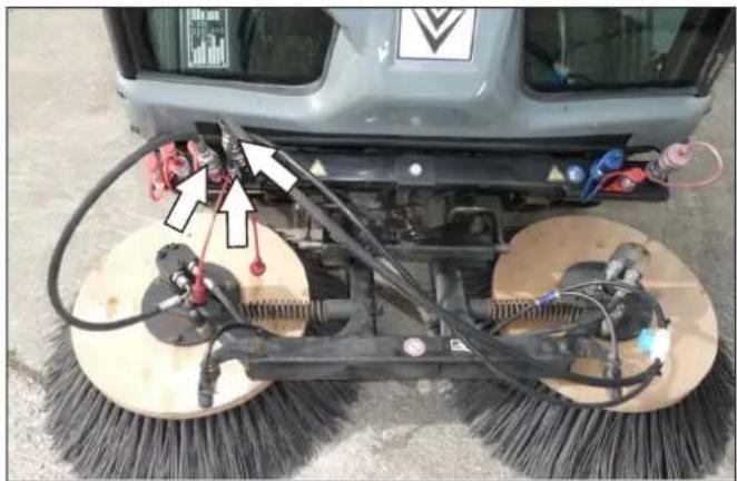
Close-up of a mechanical component with two white arrows pointing downward (no text or symbols)
natural_image
Black-and-white photo of a mechanical component with warning symbols and an arrow pointing to a section (no readable text or labels)1 Steckdose E4-Heck, 7-polig
2 Steckdose E3-Heck, 3-polig
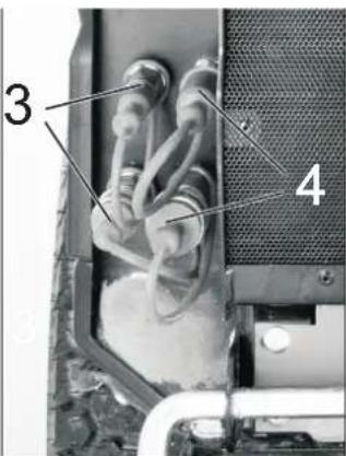
3 Hydraulikkupplungen AUX2
4 Hydraulikkupplungen 2.PTO
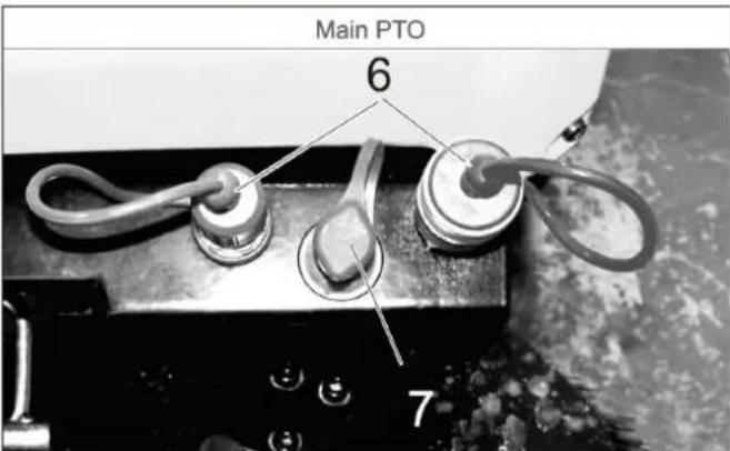
1 Hydraulikkupplungen Main PTO
2 Hydraulikkupplungen AUX2
3 Leckagekupplung

natural_image
Close-up of a mechanical device with labeled parts (1 and 2), showing internal components like a lever and plug assembly (no readable text or symbols)natural_image
Close-up of a mechanical assembly with metal plate and mounting bracket (no visible text or symbols)1 Halteblech
2 Ventil
natural_image
Black-and-white photo of a Krencher cleaning vehicle with visible components and structural details (no text or symbols)natural_image
Close-up of a car's air duct pipe with a downward arrow and numbered annotation (1), no readable text or symbols beyond annotations.natural_image
Close-up of industrial hoses with white arrows indicating movement or assembly (no text or symbols visible)natural_image
Mechanical lift assembly with a tool holder and load mechanism, showing a rightward arrow (no text or symbols)⚠️WARNUNG
Unfallgefahr!
natural_image
Close-up of a mechanical component with a circular annotation and number 1, no readable text or symbols present.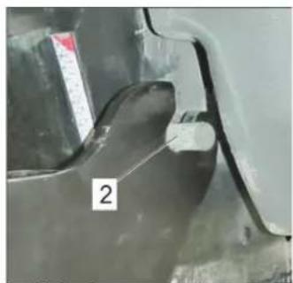
natural_image
Close-up of a mechanical component with a numbered label '2' (no readable text or symbols beyond the number)natural_image
Mechanical assembly showing a white cylindrical rod mounted on a metal frame, with two labeled components (1 and 2) indicated by arrows.1 Hebel
2 Ventil
natural_image
Mechanical frame with a white arrow indicating rotational motion, no visible text or symbolsnatural_image
Close-up of a cleaning or cleaning robot with visible brush and wiring, no text or symbols presentnatural_image
Close-up of a mechanical assembly with hoses and connectors, no visible text or symbolsnatural_image
Mechanical assembly diagram showing hoses and connectors with directional arrows indicating motion (no text or symbols present)natural_image
Close-up of a cleaning or broom with two large brush heads and attached sensors (no visible text or symbols)
natural_image
Close-up of a cleaning or cleaning tool with mounted brushes and a spray gun (no visible text or symbols)8 Anbaugerät
8.1 Wildkrautbesen
natural_image
Side view of a vehicle's front wheel assembly with labeled parts (1 and 2), showing structural components without any readable text or symbols.natural_image
Close-up of a tractor's wheel and tire assembly with labeled parts (no text or symbols beyond labels)1 Haubenverschluss
1 Befestigungsnut
2 Zentrierkegel
natural_image
Top-down view of a vehicle's rear wheel assembly with visible internal components and labeled parts (no text or symbols beyond labels)1 Verschluss
1 Befestigungsstab
natural_image
Close-up of two black agricultural machinery wheels with visible structural components and mechanical diagrams (no text or symbols)1 Oleinfülldeckel (Motor)
2 Ölmessstab
3 Ölfilter
natural_image
Close-up of mechanical components with visible wiring and a tool, no text or symbols present1 Ölablassschraube
1 Deckel
2 Ölschauglas

1 Deckel
2 Ölschauglas
3 Ölablassschraube
4 Feder
5 Filtereinsatz
6 Dichtung
1 Öleinfüllschraube
2 Ölablassschraube
natural_image
Interior view of a mechanical device with hoses and a battery, no visible text or symbolsnatural_image
Close-up of a heat exchanger or cooling unit with labeled parts (1 and 2), no readable text or symbols beyond labels1 Kühlerdeckel
2 Ablassschraube
natural_image
Close-up of a vehicle's internal engine and wheel assembly, showing hoses and components (no visible text or symbols)natural_image
Close-up of a mechanical engine component with hoses and valves (no visible text or symbols)1 Pumpenhebel
natural_image
Interior view of a vehicle's engine bay with visible tire, hoses, and battery (no text or symbols)1 Keilriemen
VORSICHT
natural_image
Close-up of a mechanical component with coiled beige tubing and a mesh grille, no visible text or symbolsnatural_image
Mechanical cleaning or cleaning device with two circular brushes and a central frame, shown with curved arrows indicating rotation (no text or symbols visible)natural_image
Close-up of a cleaning or cleaning machine with visible brush and wiring (no text or symbols)natural_image
Close-up of a mechanical assembly with pipes and tools, no visible text or symbolsnatural_image
Close-up of hands installing or adjusting mechanical components with tools and labels (no readable text)natural_image
Close-up of automotive engine components with hoses and hoses, no visible text or symbols1 Ventil
1 Ventil
1 Sprühdüse
2 Überwurfmutter
natural_image
Close-up of a mechanical component with two black arrows pointing to features, no visible text or symbols.
natural_image
Close-up of a mechanical assembly with a white arrow pointing to a component (no visible text or symbols)1 Deckel
2 Rändelschraube
natural_image
Close-up of a car's front wheel and side panel with visible tire and mounting bracket (no text or symbols)71364 Winnenden (Germany)
Tel.: +49 7195 14-0
Fax: +49 7195 14-2212
Winnenden, 2018/10/01
1 Contents
1 Contents 1
2 Information about the vehicle 2
2.1 Proper use 2
2.2 Focus on MC 50 (with sweeping suction system) 2
2.3 Focus on MC 50 (without attachments) 2
2.4 Sweeper Functions 2
3 General notes 3
3.1 Environmental protection, REACH and disposal of the worn out vehicle 3
3.2 Warranty 3
3.3 Accessories, spare parts, upgrade kits 3
3.4 Symbols in the operating instructions 3
3.5 Symbols on the machine 3
4 Safety instructions 4
4.1 General notes on safety 4
4.2 Work clothing 4
4.3 Unloading tips 4
4.4 Safety instructions concerning the operation 4
4.5 Safety information concerning the driving operation 4
4.6 Safety information concerning the combustion engine 5
4.7 Safety information concerning the transport of the appliance 5
4.8 Safety information concerning maintenance and care 5
4.9 Safety Devices 5
5 Control elements
5.1 Overview MC 50 6
5.2 Ventilation/air conditioning (option) 6
5.3 Steering column 7
5.4 Pedals 7
5.5 Lowering speed control valve (option) 7
5.6 Ceiling panel 7
5.7 Door handle 8
5.8 Waste container (sweeper) 8
5.9 Connections 8
5.10 Console MC 50 10
5.11 Joystick function 11
6 Before Startup
6.1 Prior to initial start-up 12
6.2 Refuelling 12
6.3 Fill the windshield wiper system 12
6.4 Fill water reservoir (for sweeper) 12
6.5 Adjusting driver's seat 12
6.6 Set the steering wheel position 13
6.7 Prior to start/safety test 13
6.8 Daily maintenance tasks 13
7 Operation
7.1 Driving 13
7.2 During sweeping operation 14
7.3 Restrict brush immersion depth 14
7.4 Emptying waste container 15
7.5 Turn off device 15
7.6 Frost protection 16
7.7 Transport 16
7.8 Removing the waste container/water tank 16
7.9 Removing the sweeping system 17
8 Accessory equipment 18
8.1 Weed broom 18
9 Storage 20
10 Care and maintenance 20
10.1 General notes 20
10.2 Panels 20
10.3 Cleaning 21
10.4 Maintenance intervals 22
10.5 Maintenance Works 23
10.6 Fuses 32
11 Troubleshooting 33
11.1 Faults with display 33
11.2 Faults without display 34
11.3 Towing 34
12 Technical specifications 35
12.1 Tyres 36
13 EU Declaration of Conformity 36

Please read and comply with these original operating instructions prior to the initial operation of your vehicle and store them for later use or subsequent owners.
2 Information about the vehicle
2.1 Proper use
The MC 50 is a sweeper with a sweeping suction system. In addition, or as an alternative, other attachments (not in the scope of delivery) can be attached.
Use this appliance only as directed in these operating instructions.
- The sweeper has been designed to sweep dirt and debris from outdoor surfaces.
– The appliance should not be used in closed rooms.
– The machine is not suitable for vacuuming dust which endangers health.
– The machine may not be modified. - The machine is only suitable for use on the types of surfaces specified in the operating instructions.
– The machine may only be operated on the surfaces approved by the company or its authorised representatives. - The following applies in general: Keep highly-flammable substances away from the appliance (danger of explosion/fire).
2.1.1 Foreseeable misuse
- Never vacuum up explosive liquids, combustible gases or undiluted acids and solvents. This includes petrol, paint thinner or heating oil which can generate explosive fumes or mixtures upon contact with the suction air. Acetone, undiluted acids and solvents must also be avoided as they can harm the materials on the machine.
- Never sweep/vacuum up reactive metal dusts (e.g. aluminium, magnesium, zinc), as they form explosive gases when they come in contact with highly alkaline or acidic detergents.
- Do not sweep/vacuum up any burning or glowing objects.
- The machine may not be used or stored in hazardous areas. It is not allowed to use the appliance in hazardous locations.
2.1.2 Suitable sweeping surfaces
Asphalt
■ Industrial floor
■ Screed
Concrete
■ Paving stones
2.2 Focus on MC 50 (with sweeping suction system)
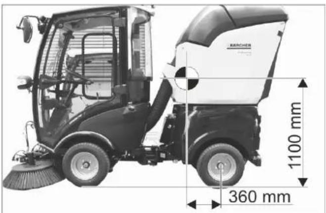
Centre of gravity position when the appliance is fully loaded.
2.3 Focus on MC 50 (without attachments)
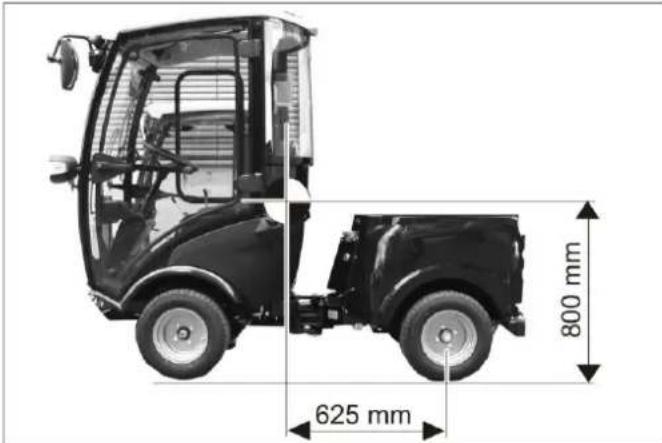
Position of centre of gravity without attachments installed.
→ Rear attachments and load statuses have an impact on the vehicle's centre of gravity and thus on the driving characteristics.
→ If not attachment is connected to the rear of the appliance, you must install the balance weights on the rear.
2.4 Sweeper Functions
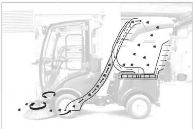
- The generated dust is bound through sprayed water.
- The side brushes transport the dust to the front of the suction opening.
- The suction turbine creates a vacuum and suctions the dust into the waste container.
3 General notes
Your sales outlet should be informed about any transit damage noted when unpacking the product.
- Read and adhere to the operating instructions and safety notes of the attachments affixed to the appliance.
- Warning and information plates on the machine provide important directions for safe operation.
– In addition to the information contained in the operating instructions, all statutory safety and accident prevention regulations must be observed.
3.1 Environmental protection, REACH and disposal of the worn out vehicle
3.1.1 Environmental protection

The packaging material can be recycled. Please do not throw the packaging material into household waste; please send it for recycling.
Batteries, oil, fuels and similar substances must not be released into the environment. Please dispose of these substances via suitable collection systems.
3.1.2 Ingredients (REACH)
The latest information on ingredients can be found under: www.kaercher.de/REACH
3.1.3 Disposal of the worn out vehicle
Worn out vehicles contain valuable recyclable materials that should be recycled properly. We recommend to cooperate with a waste management company for the disposal of your vehicle.
3.2 Warranty
The warranty terms published by our competent sales company are applicable in each country. We will repair potential failures of your accessory within the warranty period free of charge, provided that such failure is caused by faulty material or defects in fabrication. In the event of a warranty claim please contact your dealer or the nearest authorized Customer Service center. Please submit the proof of purchase.
3.3 Accessories, spare parts, upgrade kits
Only accessories, spare parts and upgrade kits that are approved by the manufacturer may be used.
To avoid risks, all repairs and replacement of spare parts may only be carried out by the authorised customer service personnel.
For additional information about spare parts, please go to the Service section at www.kaercher.com.
3.4 Symbols in the operating instructions
△DANGER
Warns about immediate danger which can lead to severe injuries or death.
⚠ WARNING
Warns about possible danger which could lead to severe injuries or death.
CAUTION
Points out a possibly dangerous situation which can lead to light injuries or property damage.
3.5 Symbols on the machine

CAUTION
Risk of burns on account of hot surfaces! Allow the exhaust to cool down sufficiently before starting work on the machine.

CAUTION
Risk of burns on account of hot hydraulic quick couplers! Wear gloves while separating the couplings.

(No text)
The Ground Truth image displays a single, solid horizontal line. According to Rule 2 (UNDERSCORE & LINE RULES), this is a stylistic or background line, not a placeholder underscore. Therefore, the OCR result must ignore it and output nothing or only meaningful text. The provided OCR content is "____", which consists of four underscores. This is an incorrect interpretation of the line as a fill-in-the-blank placeholder, violating the rule that stylistic lines must be ignored. The OCR has hallucinated underscores where none should exist based on the GT's visual context. Hence, the OCR result is inconsistent with the Ground Truth.
DANGER
Danger of crushing. Make sure that no persons are present near the arm hinges.

⚠ WARNING
Danger of crushing. Keep hands off the marked location.

(No text)
The Ground Truth image displays a single, solid horizontal line. According to Rule 2 (UNDERSCORE & LINE RULES), this is a stylistic or background line, not a placeholder underscore. Therefore, the OCR result must ignore it and output nothing or only meaningful text. The provided OCR content is "____", which consists of four underscores. This is an incorrect interpretation of the line as a placeholder, violating the rule that stylistic lines must be ignored. The OCR has hallucinated underscores where none should exist based on the GT's visual context. Hence, the OCR result is inconsistent with the Ground Truth.

CAUTION
Risk of damage. Do not enter.

△DANGER
Danger of tipping. Only drive on terrain with a max. of 10% incline.
Fill in coolant here.
△DANGER
Risk of injury due to inadvertently lowering waste container. Only perform work on the turbine while the waste container is completely lifted.
 | △WARNINGRisk of injury on account of rotating brushes.Keep your distance. |
 | Hold the detached sweeper here to lift it. |
 | △DANGERDanger of accident! Use the emergency brake when emptying the waste container. |
 | △DANGERDanger of tipping. Only empty the waste con-tainer when the appliance is placed on a level and stable ground |
 | △DANGERRisk of injury. Do not raise the waste container while people are present behind the appli-ance. |
 | △DANGERRisk of injury. Detach suction unit from the ap-pliance only while waste container is lowered. |
 | △DANGERDanger of accident. Do not drive while the waste container is raised. |
 | △DANGERRisk of fire. Do not sweep/vacuum up any burning objects. |
4 Safety instructions
4.1 General notes on safety
- The machine with working equipment must be checked to ensure that it is in proper working order and is operating safely prior to use. Otherwise, the appliance must not be used.
- If the appliance is used in hazardous areas (e.g. filling stations) the corresponding safety provisions must be observed. It is not allowed to use the appliance in hazardous locations.
4.2 Work clothing
- Always use appropriate gloves while working on the device.
- Ensure that the operator wears tight-fitting clothes. Wear safety shoes and avoid loose clothing.
- Wear suitable headgear so that braids or long hair cannot get caught in rotating parts.
- Do not wear jewellery, rings or the like during work.
4.3 Unloading tips
△DANGER
Risk of injury, risk of damage! Observe the weight of the appliance when you load it!
Unladen weight (without attachment sets) 1150 kg*
* If upgrade kits are installed, the weight is respectively higher.
△DANGER
The vehicle is not approved for crane loading. Do not use a fork lift, the appliance could get damaged.
4.4 Safety instructions concerning the operation
- The operator must use the appliance properly. The person must consider the local conditions and must pay attention to third parties, in particular children, when working with the appliance.
- Never leave the machine unattended so long as the engine is running. The operator may leave the appliance only when the engine has come to a standstill, the appliance has been protected against accidental movement, if necessary, by applying the immobilization brake and the ignition key has been removed.
- The appliance may only be used by persons who have been instructed in handling the appliance or have proven qualification and expertise in operating the appliance or have been explicitly assigned the task of handling the appliance.
- The appliance must not be operated by children or persons who have not been instructed accordingly.
- The appliance may be used by individuals with limited physical, sensory or cognitive abilities or lack of experience and knowledge if they are under supervision or were instructed regarding the safe use of the appliance and understand the resulting risks.
– Children should be supervised to prevent them from playing with the appliance. - Do not open the hood when the motor is running.
4.5 Safety information concerning the driving operation
- It is important to follow all safety instructions, rules and regulations applicable for driving motor vehicles.
- The appliance must not be operated by children, young persons or persons who have not been instructed accordingly.
- It is strictly prohibited to take co-passengers.
- Please remove the ignition key, when not in use, to avoid unauthorised use of the appliance.
- Danger of accident by reduced brake performance. Do not lay a foot mat into the driver cabin. Keep loose ob-
jects that may slip under the accelerator out of the driver cabin.
△DANGER
Risk of injury!
Prior to each use, the safety check described in the Chapter "Startup" must be conducted.
- All operating levers and switches must be in neutral prior to starting the motor. The driver must be seated when the motor is started. The drive pedal must not be pressed during the starting process.
– Fasten seat belt during driving and the performance of work.
– The vehicle may only be started while sitting in the seat.
– During transports, the front attachment frame can be lifted all the way up and locked; for this, pull the lever all the way up. - Be especially careful when working on slopes and ditches.
△DANGER
Danger of tipping!
The steering characteristics of a vehicle with articulated steering differ considerably from those of a passenger car.
→ The falling and rising gradients in the direction of travel may not exceed 25%.
→ Avoid abrupt steering movements.
→ Drive slowly when cornering.
→ Danger of tipping on unstable ground.
→ Danger of tipping with excessive sideways tilt.
Danger of tipping. Only drive on terrain with a max. of 10% incline.
→ When driving in mountains or valleys and driving laterally to slopes, avoid driving suddenly around bends.
→ Beware that the centre of gravity shifts depending on attachments and the filling level of the waste container.
→ Adjust travel speed to the ambient conditions and the load status when driving straight on and when driving around bends.
→ Beware that the braking properties are different depending on whether the vehicle is being operated in drive mode or transport mode!
4.5.1 Tyres and tyre pressure
- Check the pressure reducer on the compressor for the correct setting before correcting the tire pressure.
- Do not exceed maximum tyre pressure. The permissible tyre pressure must be read on the tyre or on the rim. If there are different values, use the lower one.
- Tyres and recommended tyre pressures are listed in the chapter "Technical Data | Tyres". In addition, there is a label with the recommended tyre pressures in the driver cabin.
4.6 Safety information concerning the combustion engine
- Read the operating instructions of the engine manufacturer before start-up and follow the safety instructions carefully.
△DANGER
Risk of injury!
- Do not close the exhaust.
- Do not bend over the exhaust or touch it (risk of burns).
-
Do not touch the combustion engine (risk of burns).
– Risk of burns Let the appliance cool off before removing the covers. -
Danger of burns! Never open the lid on the cooler while the motor has operating temperature. The container is under pressure.
- Exhaust gases are poisonous and hazardous to health, do not inhale them.
- The engine requires approx. 5 seconds to come to a standstill once it has been switched off. During this time, stay well clear of the working area.
– Risk of injury due to unprotected fan wheel. - Only use the fuels specified in the operating instructions. Risk of explosion due to the use of inappropriate fuels. Refer to Chapter "Technical data".
- When refuelling, ensure that no fuel reaches hot surfaces.
- Ensure that there is adequate ventilation or provision for diverting the exhaust gas while operating the appliance in closed rooms (risk of poisoning).
4.7 Safety information concerning the transport of the appliance
The engine is to be brought to a standstill and the appliance is to be fastened properly during transportation. Refer to Chapter "Transport".
4.8 Safety information concerning maintenance and care
- First switch off the appliance and remove the ignition key before performing any cleaning or maintenance tasks on the appliance, replacing parts or switching over to another function.
– Maintenance work may only be carried out by approved customer service outlets or experts in this field who are familiar with the respective safety regulations. - Please observe the local safety regulations regarding portable commercially used appliances.
- Articulated joint, seals, electric and electronic components must not be cleaned by means of a high-pressure cleaner or a water hose.
4.9 Safety Devices
4.9.1 Seat contact switch
If there is no driver in the driver's seat, the functions with a high danger potential will be locked.
4.9.2 Startup block
Press the brake pedal in order to start the engine.
5 Control elements
5.1 Overview MC 50
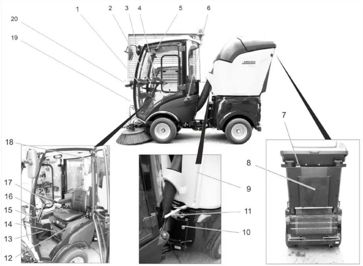
1 Door handle *
2 Steering column *
3 Work light
4 Steering wheel
5 Ceiling panel *
6 Tank lid
7 Filling nozzle for fresh water tank
8 Diffuser
9 Fresh water level display
10 Hydraulic oil sight glass
11 Hose coupling of water circulation system (option)
12 Tank indicator
13 Pedals *
14 Ventilation/air conditioning (option) *
15 Accessory blower *
16 Panel *
17 Driver's seat *
18 Emergency hammer
19 Container windshield washer system
20 Drive light/direction indicator
$$ F = f u l l $$
$$ E = \text { empty } $$
* see detailed view below
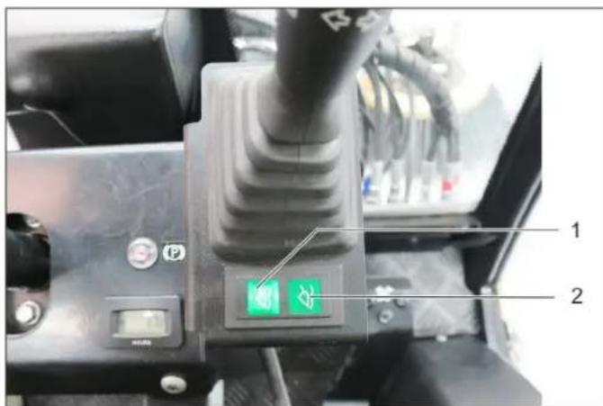
5.2 Ventilation/air conditioning (option)
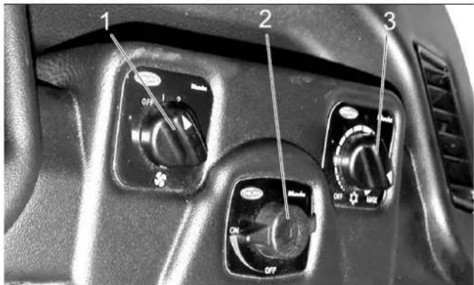
1 Switch ventilator blower
2 Temperature regulator of heater
3 Cooling capacity regulator (option)
5.3 Steering column
1 Ventilation
2 Indicator lamp for direction indicator
3 Switch for warning system
4 Clamp screw for steering wheel height adjustment
5 Operating hours counter, working hydraulics
6 Indicator lamp for parking brakes
7 Display, float position AUX 1
8 Clamp screw for steering wheel inclination adjustment
9 Display, float position, front power lifter
10 Multi-functional lifter for lights, indicators and horn
5.3.1 Multi-functional lifter for lights, indicators and horn
– Horns: Press the lever up
- Indicator: Lever to the right of left
- Parking light and dipped beam: Rotate the ring (anti-clockwise)
– High beam: Push the lever forward with the dipped beam switched on
- Flasher: Pull the lever backwards
5.4 Pedals

1 Brake pedal
2 Locking mechanism of brake pedal (emergency brake)
3 Stop work speed
4 Accelerator pedal, forwards
5 Accelerator pedal, reverse
5.4.1 Apply parking brake
→ Press the brake pedal all the way.
→ Put the lock.
→ Release the brake pedal.
5.4.2 Release parking brake
→ Press the brake pedal all the way.
→ Unlock the lock.
→ Release the brake pedal.
5.5 Lowering speed control valve (option)
The rotary knob for the lowering speed is used to adjust the lowering speed of the front implement frame.
1 Rotary knob lowering speed control valve
5.5.1 Rotary knob lowering speed front power lift
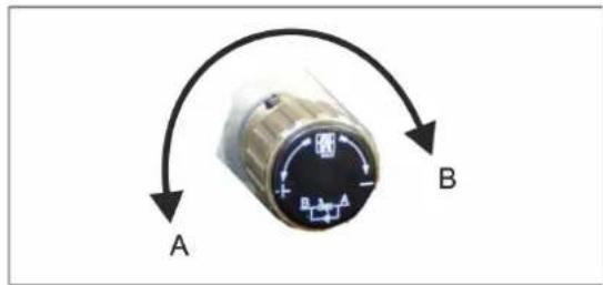
A Direction of rotation "Increase lowering speed"
B Direction of rotation "Decrease lowering speed"
→ Turning into the direction of rotation B to the limit stop locks the front power lift.
Is required for transport runs on public roads in order to lock the front power lift and thus the lowering of the attachments.
Note
5.6 Ceiling panel
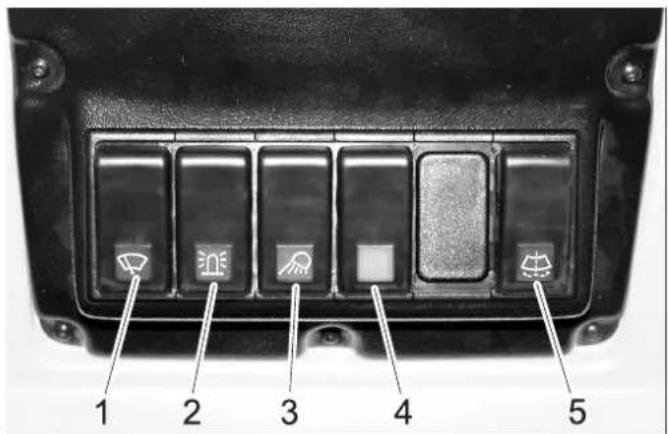
1 Switch for windshield wiper, 2 steps
2 Switch for beacon warning lamp
3 Switch for working lamp
4 Switch for option (e.g. heated outside mirrors)
5 Button for windshield wiper system
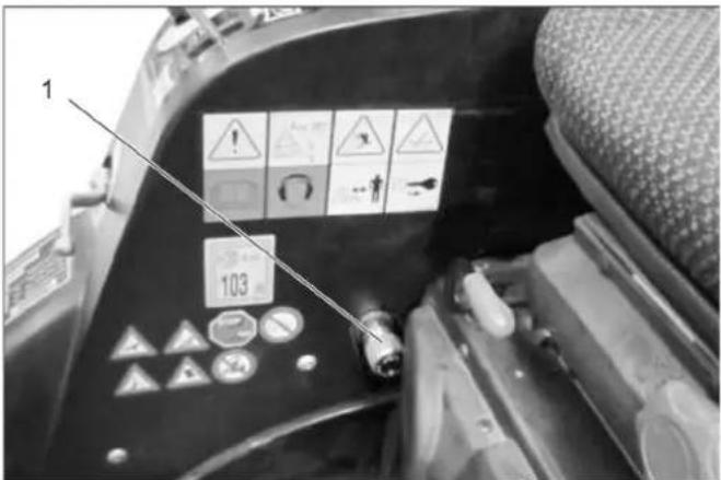
5.7 Door handle
natural_image
Close-up of a metal wire clamp with a labeled component (no visible text or symbols)1 Interior door unlock
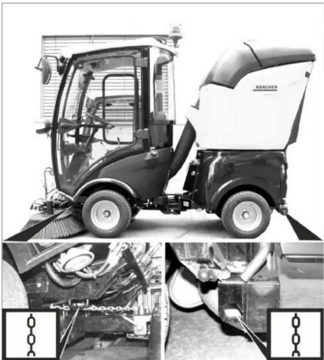
5.8 Waste container (sweeper)
⚠ WARNING
Risk of injury due to possibly falling waste container! The quick-change system of the waste container must be properly engaged.
Check the engagement indicator on both sides of the quick-change system!
natural_image
Close-up of a mechanical component with two white arrows pointing downward (no text or symbols)
natural_image
Black-and-white photo of a mechanical component with warning symbols and an arrow pointing to a section (no readable text or labels)If a black surface is visible after inserting the waste container, the container is properly engaged.
If a red surface is visible after inserting the waste container, the container is not engaged and could fall off the machine after starting to drive or when tilting the waste container.
If the red surface is visible, re-engage the waste container properly!
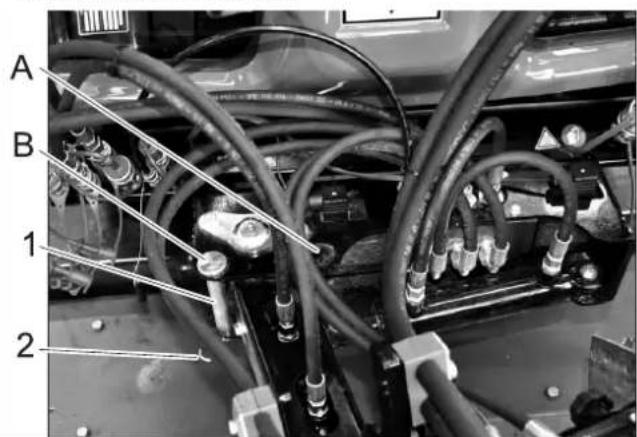
5.9 Connections
Terminology AUX: Auxiliary = additional control valve Terminology hydraulic PTO: Power Take Off = hydraulic power output
Terminology electric PTO: Power Take Off = electric power output
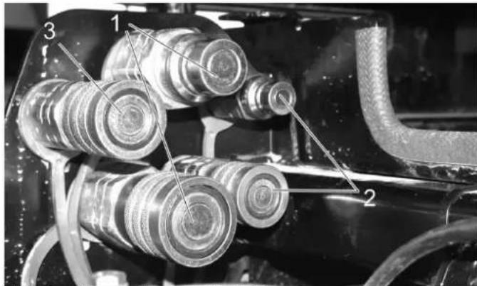
5.9.1 Front
1 Hydraulic couplings AUX2
2 Hydraulic couplings AUX1
3 Hydraulic couplings 2nd PTO
4 Water coupling (e.g. for broom coupling)
5 Socket outlet E1
6 Hydraulic couplings main PTO
7 Leakage coupling
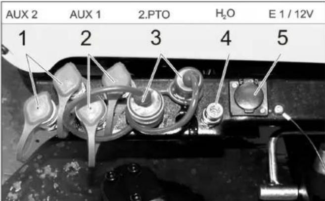
5.9.2 Back
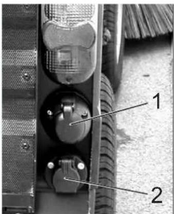
1 Socket E4 rear, 7-way
2 Socket E3 rear, 3-way
3 Hydraulic couplings AUX2
4 Hydraulic couplings 2nd PTO
5.9.3 On the rear cart
1 Hydraulic couplings main PTO
2 Hydraulic couplings AUX2
3 Leakage coupling

1 Water coupling
2 Socket E3 front
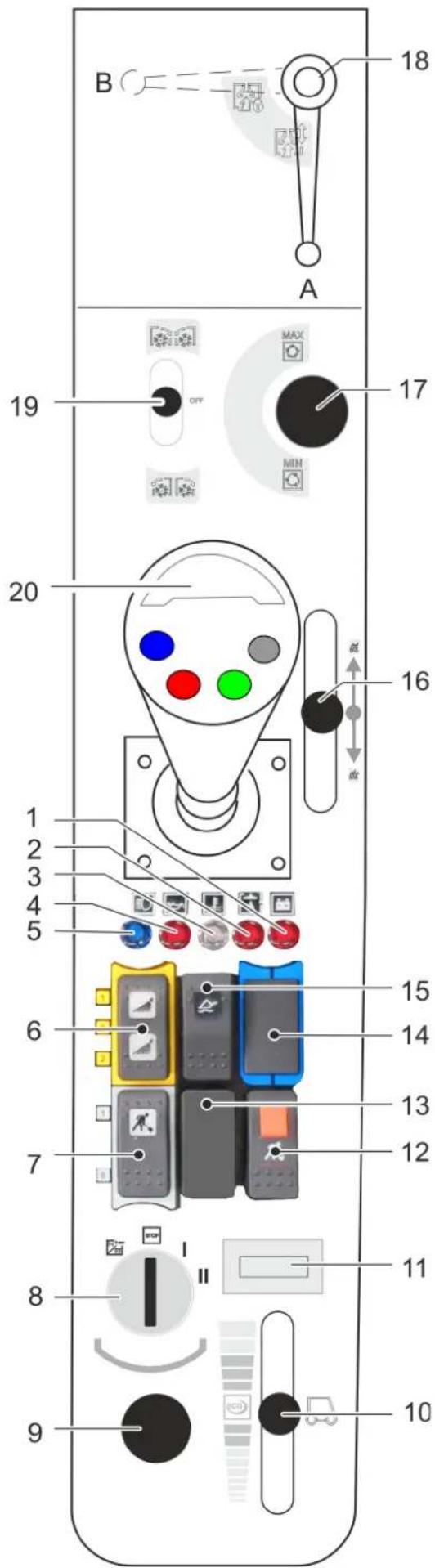
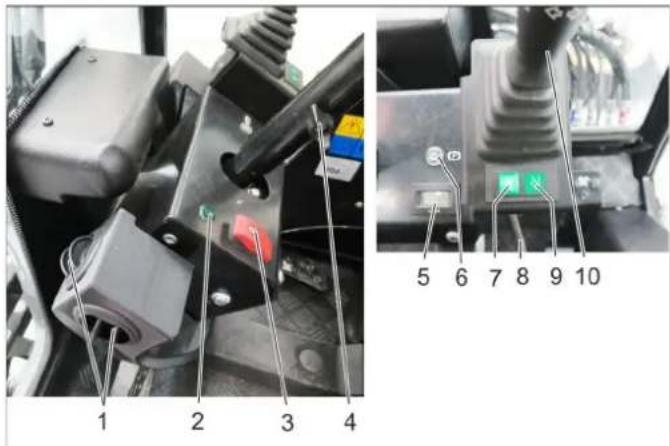
1 Warning lamp for battery charge indicator
2 Warning lamp hydraulic oil pressure
3 Warning light coolant temperature
4 Warning lamp oil pressure
5 Indicator lamp for high beam
6 Switch
Position 1: Water coupling front on
Position 0: Water coupling front off
Position 2: Switch on water circulation system (option)
7 Buttons
Position 1: Work hydraulics Main PTO on
Position 0: Work hydraulics Main PTO off
8 Ignition lock
9 On board socket 12 V
10 Hand throttle lever
11 Operating hours meter for motor
12 Pushbutton with locking mechanism
Work hydraulics Main PTO constantly on
Function only in connection with locked parking brake
and button 7
13 Not assigned
14 Not assigned
15 Main switch floating position
16 Control lever waste container
Lever forwards: Retract the waste container (only if the motor is running)
Lever backwards: Empty the waste container (only if the motor is running)
17 Setting speed PTO
18 When working with the suction mouth
Position A - suction mouth not locked
Position B - suction mouth locked
19 Control lever 2.PTO connection
Lever forwards: Side brushes on, sweeping
Lever in the centre: Side brushes stop
Lever backwards: Change of rotation direction
20 Joystick
5.10.1 Ignition switch
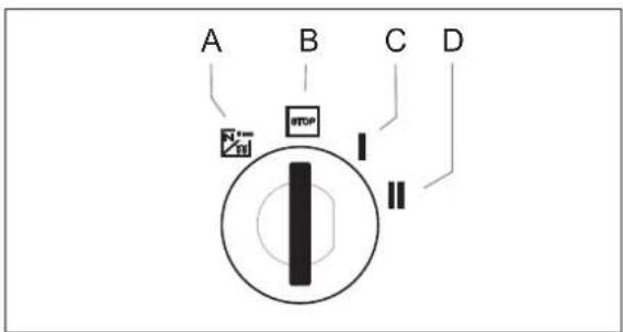
A Filament symbol : Pre-heat
B Position STOP: Engine off
C Position 1: Ignition on
D Position 2: Start the engine
A Filament symbol : Pre-heat
B Position STOP: Engine off
C Position 1: Ignition on
D Position 2: Start the engine
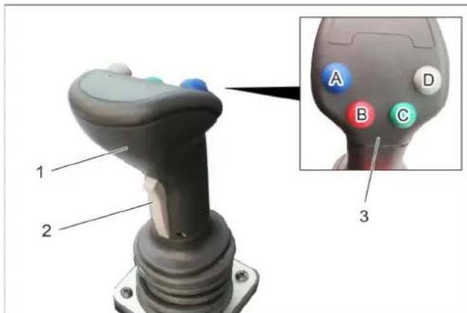
5.11 Joystick function
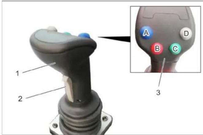
1 Joystick
2 Front button
3 Function keys
A - blue
B - red
C - green
D - grey
→ The following are controlled with the joystick: Implement frame
AUX 1 connection
AUX 2 connection
AUX connection, electrical 12 V
→ When selecting a float position, the corresponding display lights up.
5.11.1 Operations
| Front power lifter (with float position) | ||
| Main switch, float position (console) | Function button | Joystick |
| Activate Press the grey button (D) | --- | |
| Front power lifter (without float position) | ||
| Main switch, float position (console) | Function button | Joystick |
| Deactivate --- to the front / to the rear | ||
| AUX 2 connection (with float position) | ||
| Main switch, float position (console) | Function button | Joystick |
| Activate Press the green button (C) | --- | |
| AUX 2 connection (without float position) | ||
| Main switch, float position (console) | Function button | Joystick |
| Deactivate --- move to the left / right | ||
| AUX 1 connection | ||
| Button to the front (joystick) | Function button | Joystick |
| Press and hold --- move to the left / right | ||
| AUX connection, electrical 12 V | ||
| Button to the front (joystick) | Function button Joystick | |
| --- Press the blue or red function buttons (A/B) | --- | |
5.11.2 Display, float position
1 Display, float position AUX 1
2 Display, float position, front power lifter
→ When selecting a float position, the corresponding display lights up.
6 Before Startup
6.1 Prior to initial start-up
→ Attach the document pouch to the rear window as instructed in the enclosed instructions.
6.2 Refuelling
⚠Danger
Risk of explosion!
- Do not refuel the machine in enclosed spaces.
– Smoking and open flames must be strictly avoided. - Ensure that no fuel reaches the hot open surfaces.
→ Switch off engine.
→ Open fuel filler cap.
→ Fill in diesel.
Only use the fuels specified in the Operations Manual.
→ Insert the fuelling gun as deep as possible into the fuel nozzle. Do not add any more fuel once the fuelling gun stops according to the settings.
→ Wipe off any spilt fuel and close fuel filler cap.
6.2.1 Fuelling using a can
- Estimate the fuel requirement in order to avoid overflows.
6.3 Fill the windshield wiper system
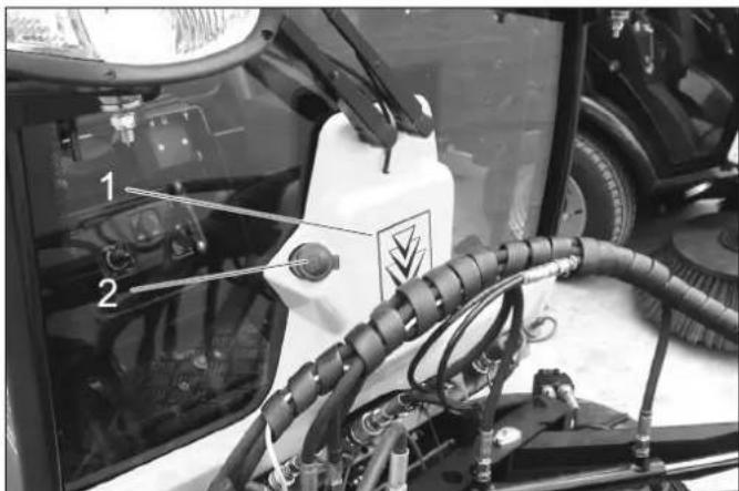
1 Container windshield washer system
2 Cover
→ Remove the lid.
→ Fill in liquid.
→ Close the lid.
6.4 Fill water reservoir (for sweeper)
→ Unscrew the lid of the filler neck for fresh water.
→ Fill the water reservoir.
NOTICE
Do not insert the water hose to fill the water tank (avoids water getting sucked back in).
→ Shut off water supply.
→ Remove the water supply hose and close the filler neck for fresh water.
6.4.1 With a water circulation system (option)
→ Fill water into the waste container (max. 50 litres).
6.5 Adjusting driver's seat
△DANGER
Danger of accident. Do not adjust the driver's seat while driving.
6.5.1 Standard seat
1 Lever for seat adjustment
2 Rotary handle for spring resistance
3 Inclination adjustment back rest
4 Display of spring setting
5 Adjustment wheel arm rest height
→ Sit on the driver's seat.
→ Pull the seat adjustment lever up and slide the seat into the desired position.
→ Release the seat adjustment lever and lock the seat in place.
→ Set the inclination of the back-rest with the rotary handle for back-rest inclination.
→ Adjust the height of the arm rests via the adjustment wheels.
→ Adjust the rotary handle of the spring resistance so that the pointer of the spring resistance display is in the green area.
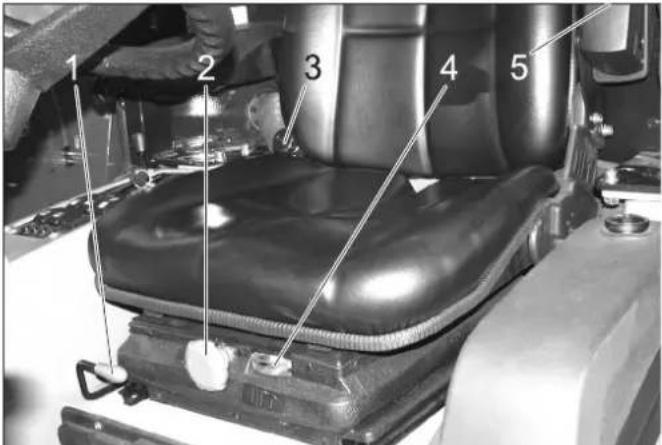
6.5.2 Comfort seat (optional)

1 Lever for seat adjustment
2 Height adjustment
To lower: Pull out the knob
To lift: Push the knob (while the motor is running)
3 Inclination adjustment back rest
4 Seat belt
→ The damping of the driver seat takes place automatically.
6.6 Set the steering wheel position
△DANGER
Danger of accident. Do not adjust the steering wheel position while driving.
natural_image
Close-up of a mechanical device with labeled parts (1 and 2), showing internal components and no readable text or symbols.1 Clamp screw for steering wheel height adjustment
2 Clamp screw for steering wheel inclination adjustment
→ Loosen the clamp screw for steering wheel height adjustment.
→ Set the steering wheel to the desired height.
→ Tighten clamping screw.
→ Loosen the clamp screw for steering wheel inclination adjustment.
→ Set the desired inclination of the steering wheel column.
→ Tighten clamping screw.
6.7 Prior to start/safety test
△DANGER
Risk of accidents, injuries. If one point of the safety check is not fulfilled, the appliance must not be taken into operation, but must be repaired.
The following safety tests must be conducted prior to each operation:
6.7.1 Safety check
Perform the safety check while the ignition is switched on (position 1).
→ With released parking brake: Release accelerator pedal, switch off work hydraulics Main PTO - the motor must not start when turning the ignition key (position 2).
→ With actuated brake pedal: Switch on work hydraulics Main PTO - the motor must not start when turning the ignition key (position 2).
→ With running motor: Switch on work hydraulics Main PTO, relieve driver seat - the work hydraulics Main PTO must switch off
6.8 Daily maintenance tasks
Carry out the daily maintenance tasks (see section "Maintenance and Care").
7 Operation
△DANGER
Danger of crushing. Make sure that no persons are present near the arm hinges.
Danger of burns, crushing. Only use the appliance if all casing parts have been attached.
CAUTION
Risk of damage by overheating of the power transmission and the brake. Only use the brake pedal during travel, if the appliance does not stop when the accelerator pedal is released or briefly activated.
Danger of damage due to lack of lubrication. If the oil pressure warning lamp lights up during operation, switch the engine off immediately and remediate the malfunction.
Risk of damage due to overheated engine or overheated hydraulic oil. If the warning lamps for engine temperature or hydraulic oil temperature lights up, set the engine speed to idle (do not turn the engine off) and perform the measures in the Chapter "Malfunctions".
Danger of damage to the hydraulic hoses of the sweeping unit. Do not lower the brush to the ground or the platform any lower than the position of the wheels (for sweepers).
7.1 Driving
⚠ WARNING
The device has a central pendulum joint in order to provide maximum manoeuvrability.
This enables both vehicle halves to move laterally to the direction of travel independently from one another.
Due to this special feature, the driver does not receive timely feedback from the rear half of the vehicle.
It is for this reason that the driver has to use the mirrors to watch the movements of the rear half of the vehicle.
Vehicles with articulated steering are much more sensitive to steering movements than passenger cars – particularly when taking bends at high speed, on snow, ice and wet/loose ground as well as during turning manoeuvres on slopes.
It is therefore extremely difficult to stabilise a vehicle with articulated steering by countersteering!
1 Brake pedal
2 Locking mechanism of brake pedal (emergency brake)
3 Stop work speed
4 Accelerator pedal, forwards
5 Accelerator pedal, reverse
7.1.1 Release parking brake
→ Press the brake pedal all the way.
→ Turn the lock toward the rear.
→ Release the brake pedal.
7.1.2 Start the engine
→ Remove your foot from the accelerator pedal.
→ Set engine speed to MIN position.
→ Press the brake pedal all the way down.
The indicator lamp for the emergency brake must be illuminated.
→ With low exterior temperatures, turn the ignition key to pre-heating setting for about 3 seconds.
→ Turn the ignition key to "Start engine" and hold it there until the engine starts up.
→ Release the ignition key. The ignition key turns to position "1", engine on.
→ Release the brake pedal.
CAUTION
Risk of damage by overheating of the power transmission and the brake. Do not drive appliance while brake is activated.
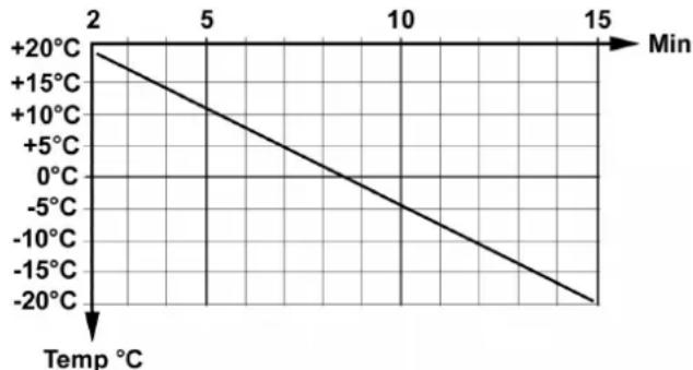
→ After a cold start, let the appliance warm up while the engine speed is set to MIN, so that the hydraulic oil can reach operating temperature. The pre-heating time depends on the ambient temperature and can be read from the diagram below.
line
| Time (Min) | Temperature (°C) | |------------|------------------| | 2 | +20 | | 5 | +15 | | 10 | +10 | | 15 | +5 | | 20 | 0 | | 25 | -5 | | 30 | -10 | | 35 | -15 | | 40 | -20 |7.1.3 Driving
ATTENTION
The speed is reduced when you release the gas pedal; a property that is different to passenger cars.
In transport mode, the speed reduction due to braking when you let go of the gas pedal is lower than in work mode.
→ Raise the working machine.
→ Raise the suction opening and the side-brushes (for sweepers).
→ Set engine speed to ECO.
→ Press accelerator pedal down slowly.
→ Control the driving direction with the steering wheel.
7.1.4 Stop
→ Release the accelerator pedal or drive backwards for a moment, the machine brakes automatically and stops. Only use the brake pedal if the appliance does not stop in spite of applying the above measures.
CAUTION
Risk of damage to the drive system. Use the brake only in emergencies and as an emergency brake while the appliance is not moving, not as an operational brake.
7.1.5 Driving over obstacles
△WARNING
Risk of damage! Raise the side-brushes and the suction opening before overtaking hurdles.
Obstacles up to 150 mm in height:
→ Bypass the obstacles slowly and carefully at an angle of 45^ .
Obstacles more than 150 mm in height:
→ Only drive over these obstacles using a suitable ramp.
⚠ Warning
Risk of damage! Ensure that the vehicle does not get stuck up.
7.2 During sweeping operation
CAUTION
Do not sweep up packing strips, wire or similar objects as this may choke up the suction canal.
To avoid damaging the floor, do not continue to operate the sweeping machine in the same position.
NOTICE
To achieve an optimum cleaning result, the driving speed should be adjusted to take specific situations into account. During operation, the waste container should be emptied at regular intervals.
→ Start the engine and let it warm up.
→ Set engine speed to ECO.
→ Lever (18) at position A. Suction port not locked
→ Adjust the side brush speed.
→ Press the lever (19) to the front. Side brush sweeping is switched on.
→ Pushbutton (7) Switch on work hydraulics Main PTO. Suction turbine is running.
→ Wen sweeping dry waste: Switch on switch (6) for irrigation of the side brush. Switch on the water circulation system if needed (option).
→ Go about further operation using the joystick; for more on this, see chapter 5.10 "Joystick function".
7.2.1 Deflect large objects
Medium-sized objects (such as drink cans) can be suctioned up by the appliance.
Large objects (such as branches) can be deflected to the side by a brief reversal of the side brush rotation direction.
→ Pull the lever (19) briefly backwards.
The direction of rotation of the side brush changes.
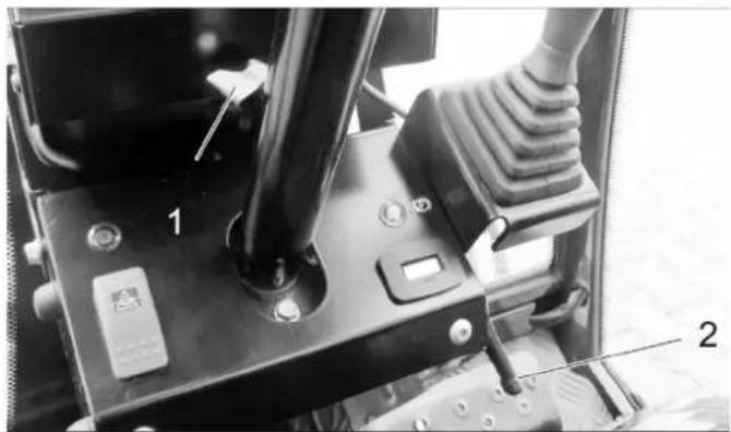
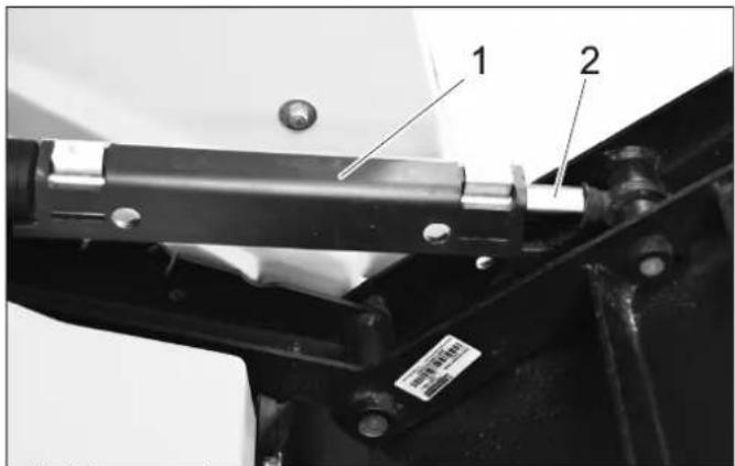
7.3 Restrict brush immersion depth
If soft brushes are used, it may become necessary to restrict their immersion depth too prevent excessive deformation of the bristles during the sweeping process.
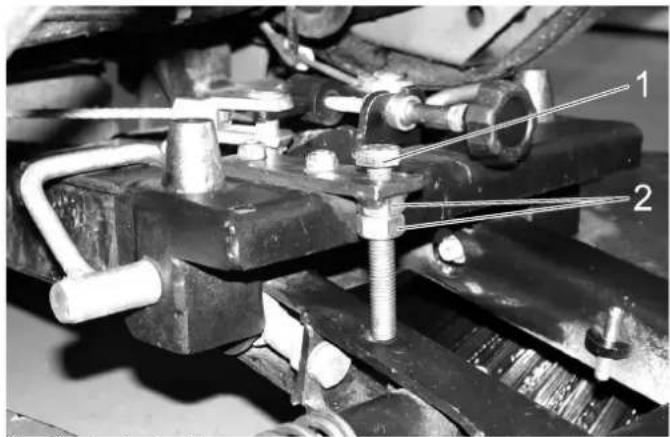
1 Screw
2 Locknut
→ Loosen the locknut.
NOTICE
The further the screw is screwed toward the bottom, the lower the immersion depth of the brushes.
→ Tighten the locknut.
7.4 Emptying waste container
△DANGER
Risk of injury! While reversing, ensure that there is nobody in the way, ask them to move if somebody is around.
Danger of tipping. Empty waste container only while the appliance is on stabile ground, which is tilted neither to the rear nor the side.
Maintain the required safety distance while emptying on dumps or ramps.
Danger of accident! Use the emergency brake when emptying the waste container.
Risk of injury! Switch off the suction turbine before emptying the waste container.
Risk of injury! When emptying the waste container, care should be taken to ensure that no persons or animals are within its swivelling range.
Danger of crushing! Never reach into the rod assembly for the drainage mechanism.
NOTICE
Always raise the waste container completely up to the end position.
→ If a sweeper is used: Raise the side brushes and suction mouth. If an appliance carrier is used: Raise the work machine.
→ Stop the machine.
→ Switch off the irrigation of the side brush using switch (6).
→ Wait for approx. 20 seconds.
→ With sweeper: Switch off suction turbine using pushbutton (7).
With appliance carrier: Switch off working equipment using pushbutton (7).
→ Empty waste container. Lever (16) backwards.
→ Waste container retracted again after emptying. Lever (16) forwards.
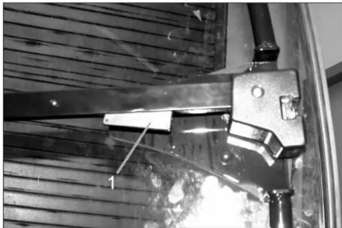
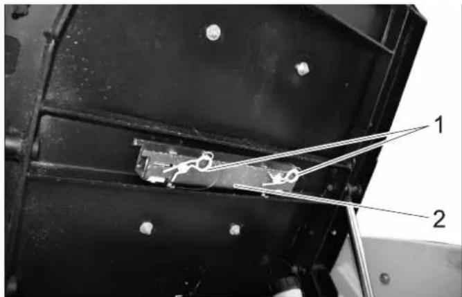
7.4.1 In addition, when working with a water circulation system (option)
→ Clean the filter in the waste container using a water jet.
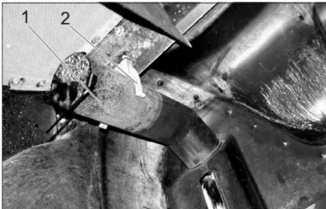
1 Filter
2 Bracket
→ Swivel the filter out of holder and pull it off.
→ Clean filter under running water.
→ Raise waste container.
1 Halting plate
2 V a l v e
→ Rotate the support plate counter-clockwise and remove it.
→ Remove and clean the valve.
7.5 Turn off device
If an optional 3rd side brush or weed broom: Swivel in and raise, see chapter "8.1 Weed broom".
→ If a sweeper is used: Raise the side brushes and suction mouth.
If an appliance carrier is used: Raise the work machine.
→ Stop the machine.
→ Switch off the irrigation of the side brush using switch (6).
→ Wait for approx. 20 seconds.
→ With sweeper: Switch off suction turbine using pushbutton (7).
With appliance carrier: Switch off working equipment using pushbutton (7).
→ Set engine speed to MIN position.
→ Let the engine idle for 1 to 2 minutes.
→ Turn ignition key to "STOP" and remove it.
→ Activate parking brake.
7.6 Frost protection
→ If frost is expected, check whether there is enough anti-frosting agent in the cooling water.
→ Empty the water reservoir and the pipe system; refer to chapter "Maintenance Work/Empty water reservoir") (option).
7.7 Transport
⚠ WARNING
Risk of injury and damage! Observe the weight of the appliance when you transport it.
Risk of accident: The appliance must be secured against slippage during transport.
CAUTION
Risk of damage! Never attach the appliance to the brush system or tow it (for sweepers).
→ Switch the appliance off and lock the emergency brake.
natural_image
Black-and-white photo of a Kirschler cleaning or cleaning vehicle with visible components and structural details (no text or symbols)→ Secure the vehicle on the fixing eyelets on the left and the right using tie down straps.
7.8 Removing the waste container/water tank
With the optional collecting carriage (order no. 2.851-043) the waste container/water tank can be removed from the sweeper MC 50.
At the same time, the collecting carriage is used for storing the sweeping system removed from the unit.
→ Empty waste container and water tank prior to removal.
7.8.1 Depressurizing the hydraulic system
→ Turn the ignition lock to position „1“ (do not start the engine).
→ Set the preselection switch in waste container position.
→ Move the lever for waste container emptying back and forth.
→ Turn the ignition lock to the "Engine OFF" position.
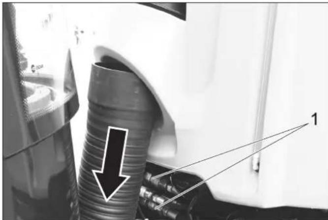
7.8.2 Removing the suction hose
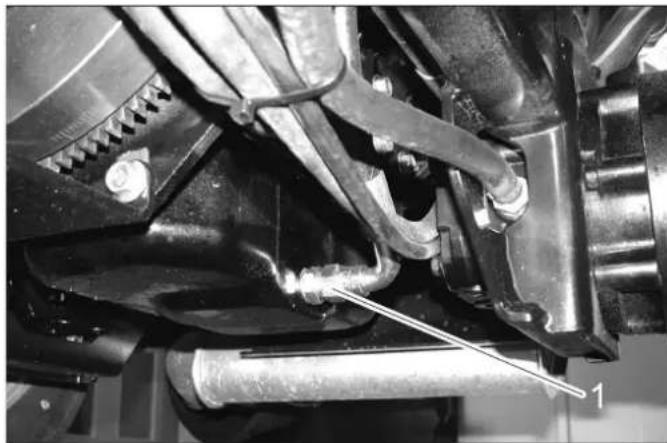
→ Pull the suction hose from the bottom out of the waste container (arrow).
natural_image
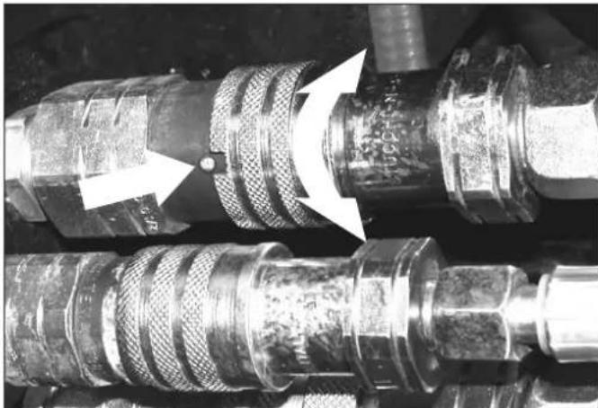
Close-up of a car's exhaust pipe with a downward arrow and numbered annotation (1), no readable text or symbols beyond annotations.7.8.3 Disconnecting the hydraulic couplings CAUTION
Risk of burns on account of hot hydraulic quick couplers! Wear gloves while separating the couplings.
→ Check, if the locking ball is in alignment with the opening. If not, turn the locking sleeve until the ball and opening are in alignment.
→ Pull the coupling back at the locking sleeve.
natural_image
Close-up of industrial pipe fittings with white arrows indicating a component (no visible text or symbols)7.8.4 Disconnecting water couplings and electrical plug connections
→ Separate the water coupling.
→ Separate the electric connectors.
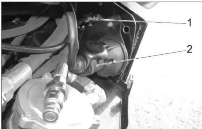
1 Water coupling
2 Electric connectors
7.8.5 Attaching collecting carriage on the waste container.
→ Align the collecting carriage parallel to the appliance.
→ Insert the collecting carriage parallel to the appliance.

natural_image
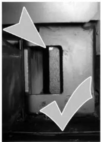
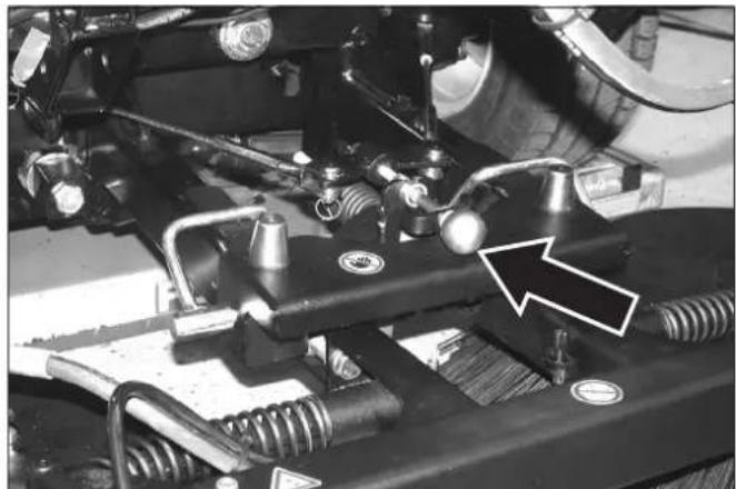
Mechanical lift assembly with a tool holder and load mechanism, showing a rightward arrow (no text or symbols)⚠ WARNING
Risk of accident!
Prior to lifting the waste container, check if the bolts on the left and right are correctly seated in the retainer. Lifting is only permitted if the bolt is seated correctly!
→ Check seating of the bolt on the left and right side.
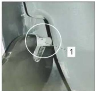
natural_image
Close-up of a mechanical component with a circular annotation and number 1, no readable text or symbols present.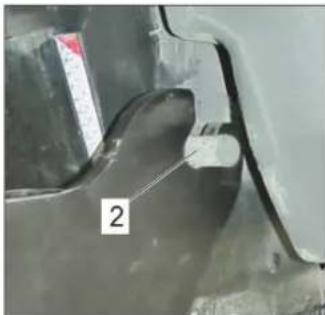
natural_image
Close-up of a metallic mechanical component with a labeled section '2' (no readable text or symbols beyond the label)1 INCORRECT: Bolt is not properly seated in the retainer
2 CORRECT: Bolt is safely seated in the retainer
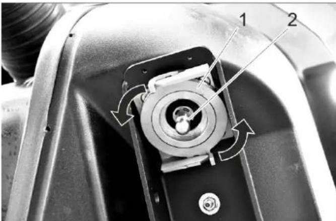
7.8.6 Raise waste container
→ Using the thin end of the lever, turn the valve clockwise until it hits the stop.
→ Pump with the lever to raise the container.
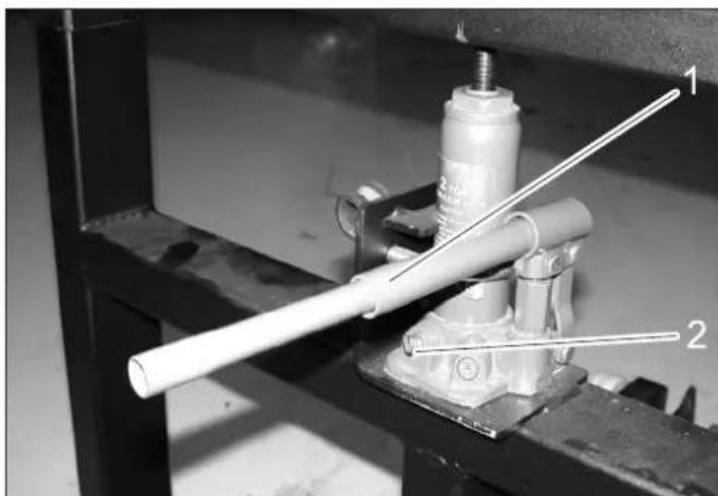
natural_image
Mechanical assembly showing a white cylindrical rod mounted on a metal frame, with two labeled parts (1 and 2) indicating components.1 Lever
2 V a l v e
→ Pull the carriage with the waste container/water tank back by approximately 30 cm.
→ Continue raising the container until the front end is at a sufficient distance from the supporting surface.
→ Fully pull back the carriage with the waste container/water tank.
7.8.7 Attaching the waste container/water tank
→ Use the reverse sequence to reinstall the waste container on the unit.
→ Turn the valve anticlockwise to lower the container.
7.9 Removing the sweeping system
→ Swing the brush holder at the collecting carriage upwards and let it lock into place.
→ Lower the brush.
→ Turn off the appliance.
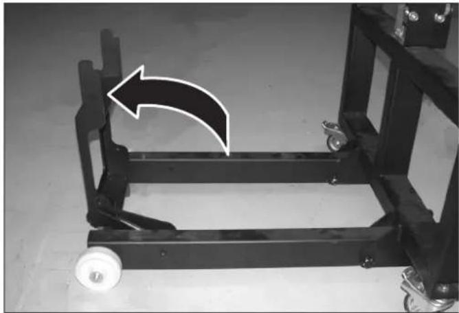
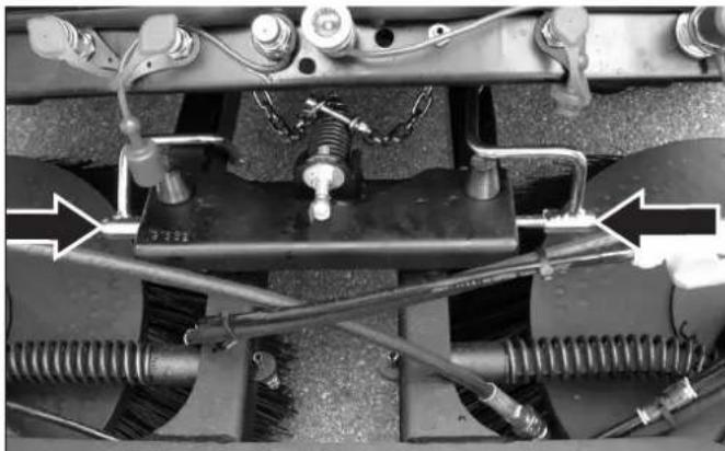
natural_image
Mechanical frame with a white arrow indicating rotational motion, no visible text or symbols→ Separate the couplings (arrows).
natural_image
Close-up of a cleaning or cleaning robotic brush on a wooden floor, with no visible text or symbols.→ Raise the brush manually and unhook the wire rope.
natural_image
Close-up of a mechanical assembly with hoses, springs, and a vehicle wheel (no visible text or symbols)→ Swing the safety pin forward and pull it out.
natural_image
Mechanical assembly diagram showing springs, hoses, and a central component with directional arrows (no text or symbols)→ Raise the sweeping system and put it on the collecting carriage.
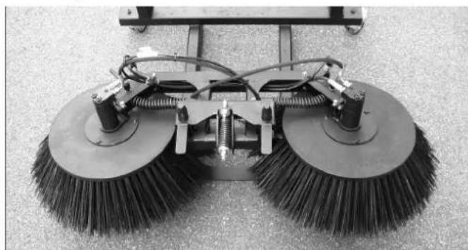
natural_image
Close-up of a cleaning or broom with two large brush heads and visible wiring (no text or symbols)
natural_image
Close-up of a cleaning or cleaning tool with mounted brushes and wiring (no visible text or symbols)8 Accessory equipment
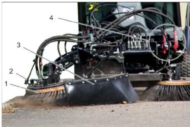
8.1 Weed broom

1 Weed broom
2 Water-spraying equipment
3 Splash guard
4 Hydraulic couplings main PTO
8.1.1 Proper use
The upgrade kit weed broom is attached to the front appliance carrier.
It is used to remove:
- encrusted dirt
– Growth between paver stones
- and similar cleaning tasks.
→ The upgrade kit can be used in conjunction with the 2-broom system.
→ The weed broom is suitable for all surfaces.
→ Street surfaces or similar surfaces can become scratched, even if the weed broom is used in floating position.
8.1.2 Important notes
→ When driving on public roads, you must adhere to the local regulations.
→ Adhere to the local accident prevention guidelines and safety notes.
→ Follow the safety and operating instructions in the towing vehicle manual.
8.1.3 Prerequisites for operation
→ Front power lift must be attached to the vehicle.
8.1.4 Installing the weed broom
→ Attach the completely pre-assembled weed broom to the front power lift, and secure it.
Note
If the weed broom is supplied as an attachment kit, then assemble it beforehand in accordance with Installation instructions 0.083-359.0 enclosed with the attachment kit.
→ Establish hydraulic connections PTO, AUX 1 and AUX 2 on the vehicle.
→ Create a water connection.
8.1.5 Operation
△DANGER
Risk of injury if you touch the rotating weed broom. Watch for sufficient safety clearance to people when adjusting and working.
Risk of injury on account of projected rocks or dirt. Correctly adjust the spray guard and keep sufficient clearance to persons.
△DANGER
Accident risk on account of decreased steering performance. When you press down on the weed broom, the weight it taken off the front wheels. This can lead to a decreased steering effect. In this case, lift the weed broom up immediately.
→ The weed broom and the front appliance carrier are operated using the joystick.
1 Bolt for transport lock
2 Spring pin
A Operation
B Transport
→ Pull out the transport lock bolt.
→ Swivel the front appliance carrier to the right.
→ Insert the transport lock bolt into the operating position and secure with spring cotter pin.
→ Lower the front appliance carrier until the broom touches the ground.
→ Tighten the screw.
→ Tighten the locknut.
→ Start the motor.
→ Raise the front appliance carrier.
→ Roll (tilt at the side) the weed broom into the required position, tilt it (forwards) and swivel it.
→ For cleaning work, switch on the working hydraulics for the main PTO. The weed broom rotates.
→ Lower the front appliance carrier into the floating position.
Note:
Usually, the front appliance carrier is lowered into the floating position. If you desire an increased cleaning performance, the weed broom can be briefly pushed down.
→ Perform cleaning process.
8.1.6 Joystick function
1 Joystick
2 Front button
3 Function keys
A - blue
B - red
C - green
D - grey
→ The following are controlled with the joystick: Implement frame
AUX 1 connection
AUX 2 connection
AUX connection, electrical 12 V
→ When selecting a float position, the corresponding display lights up.
8.1.6.1 Operations
| Front power lifter (with float position) | ||
| Main switch, float position (console) | Function button | Joystick |
| Activate Press the grey | button (D) | --- |
Front power lifter (without float position)
| Main switch, float position (console) | Function button Joystick |
| Deactivate --- to the | front / to therear |
Weed broom arm (with float position)
| Main switch, float position (console) | Function button Joystick | |
| Activate Press the | green button (C) | --- |
Press / lift the weed broom arm (without float position)
| Main switch, float position (console) | Function button Joystick | |
| Deactivate Press and hold move to the left/right | ||
Swivel in / out the broom arm
| Button to the front (joystick) | Function button Joystick |
| --- --- move to the left / | right |
Tilt the broom head (forwards)
| Function buttonBlue | Function buttonRed | Joystick |
| Press and hold | --- move to the left /right | |
Roll the broom head (tilt at the side)
| Function button Blue | Function button Red | Joystick |
| --- Press and hold | move to the left / right | |
8.1.7 Transport run
⚠ WARNING
Increased injury risk if working with unfavourably placed weed broom. To minimise the injury risk, align the broom as described below while you work.
→ Raise the front appliance carrier.
→ Tilt the broom forwards.
→ Swivel in the broom in a clockwise direction.
→ Insert the transport lock bolt into the transport position and secure with spring cotter pin.
→ Mount the spray guard so that the broom is covered.
9 Storage
⚠ WARNING
Risk of injury and damage! Note the weight of the appliance in case of storage.
If the vehicle is not used for a longer period of time, observe the following points:
→ Park the vehicle at a safe, level and dry place.
→ If an optional 3rd side brush or weed broom: Swivel in and raise, see chapter "8.1 Weed broom".
→ If a sweeper is used: Raise the side brushes and suction mouth.
If an appliance carrier is used: Raise the work machine.
→ Turn ignition key to "STOP" and remove it.
→ Secure vehicle against rolling away, lock parking brake.
→ Change the engine oil and the oil filter.
If frost is expected, check whether there is enough anti-frosting agent in the cooling water.
→ Empty the water reservoir and the pipe system; refer to chapter "Maintenance Work/Empty water reservoir") (option).
→ For the water circulation system (option) drain the water from the waste container.
→ Clean the inside and outside of the sweeper.
→ Charge battery approx. every 2 months.
→ Disconnect the negative terminal of the battery if the appliances is not used for more than 4 weeks.
10 Care and maintenance
10.1 General notes
→ First switch off the appliance and remove the ignition key before performing any cleaning or maintenance tasks on the appliance, replacing parts or switching over to another function.
→ The battery must be disconnected prior to working on the electrical system.
→ Lock parking brake.
→ Maintenance work may only be carried out by approved customer service outlets or experts in this field who are familiar with the respective safety regulations.
10.1.1 Safety measures for raised waste container (for sweepers)
Install the safety support prior to working on the machine with the waste container raised:
1 Spring pin
2 Safety support
→ Pull out the spring plug.
→ Remove the safety support from the waste container.
1 Safety support
2 Piston rod
→ Insert safety support onto the piston rod of a lifting cylinder for the waste container.
10.2 Panels
10.2.1 Remove/attach engine panels
⚠ WARNING
Risk of burns Let the appliance cool off before removing the covers.
natural_image
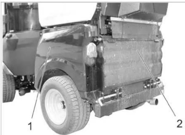
Side view of a vehicle's front wheel assembly with labeled parts (1 and 2), showing structural components without any readable text or symbols.1 Side engine panel
2 Radiator grid
The completion of the difference maintenance tasks, the engine panels must be removed.
10.2.2 Remove the engine's side panels
natural_image
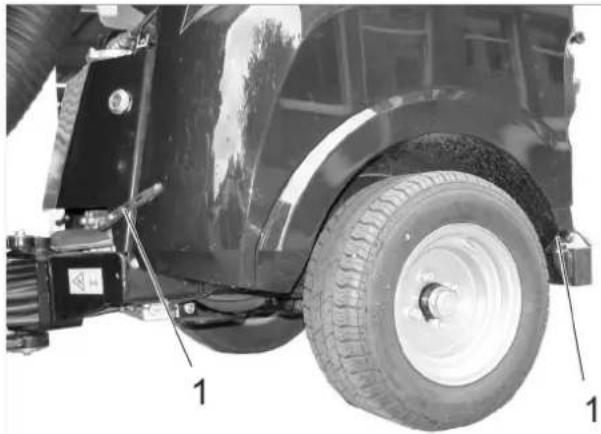
Close-up of a tractor's wheel and tire assembly with labeled parts (no text or symbols beyond labels)1 Cover lock
→ Open both hood latches.
→ Raise the panels and swivel them to the top and out.
→ Remove panels.
10.2.3 Install the engine's side panels
1 Fastening bushing
2 Centering cone
→ Thread the bottom end of the panel behind the wheel.
→ Swivel the panel up to the appliance and hook the top edge of the panel into the fastening bushing.
→ Close the hood latches.
10.2.4 Remove the radiator grill
natural_image
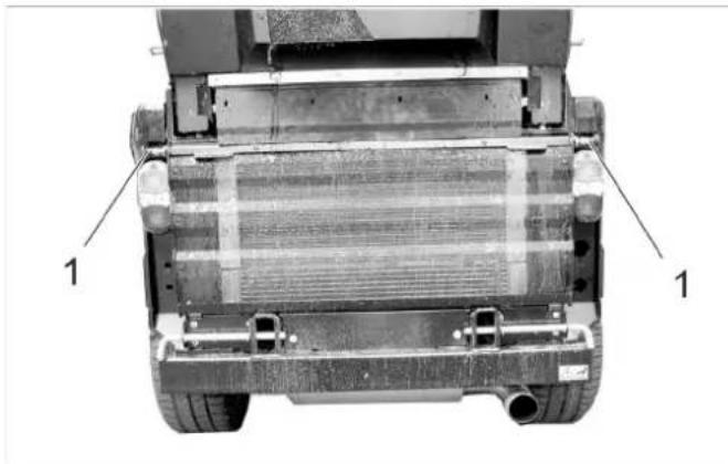
Top-down view of a vehicle's rear wheel assembly with visible internal components and mounting brackets (no text or symbols)1 L o c k
→ Open both latches (pull the latch out, rotate about 90° and release).
→ Swivel the radiator grill toward the top, pull up and remove.
10.3 Cleaning
→ Empty the waste container (for sweepers).
→ Raise the working machine.
→ Raise the side brush and the suction port.
→ Park the machine on an even surface.
→ Set engine speed to MIN position.
→ Turn ignition key to "STOP" and remove it.
→ Lock parking brake.
10.3.1 Cleaning the device
Clean appliance daily after finishing work.
CAUTION
Risk of damage!
Shaft seals, electrical components and hydraulic valves must not be cleaned using a high pressure water jet.
Do not rinse the engine with water.
When cleaning the appliance with a high pressure cleaner, adhere to the respective safety instructions.
Radiator fins must only be cleaned with compressed air (max. 5 bar), not with water.
Do not use aggressive cleaning agents.
In order to protect the air filter only wash the rear of the appliance while the motor is shut off.
→ Check the vehicle for oil and fuel leaks to prevent fires. Get customer service to fix the leaks.
→ Rinse the side brush with a water jet (for sweepers).
→ Rinse the suction opening with a water jet (for sweepers).
→ Check front power lifter for ease of movement (raising and lowering).
→ Check the easy movement of the suction opening and the bulk waste flap (for sweepers).
To avoid fires, keep the engine, muffler, battery and fuel tank free of plant residue and oil.
→ Check the engine for contamination, clean with a brush or compressed air if required
10.3.2 Clean the radiator
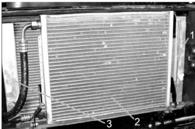
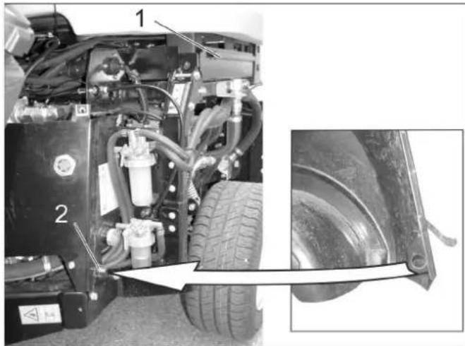
1 Fastening rod
2 Cooler for air conditioning (option)
3 Combi cooler
→ Check the radiator for contamination.
→ Remove large object by hand.
→ Remove contamination with a soft brush or compressed air.
Swivel the radiator of the air conditioning to the side:
→ Release the fastening rod from the holder and swivel it up.
→ Swivel the radiator of the air conditioning to the side.
10.3.3 Rinse the suction channel and the waste container (for sweepers).
→ Start the appliance.
→ Set engine speed to ECO.
→ Place the water hose in front of the suction opening and open the water supply.
→ Switch on the suction turbine.
→ Let the suction turbine run for approx. 2 minutes.
→ Switch off the suction turbine.
→ Empty waste container.
→ Rinse the interior of the waste container and the cover grid of the suction channel with a water jet.
10.4 Maintenance intervals
NOTICE
In order to safeguard warranty claims, all service and maintenance work during the warranty period must be carried out by the authorised Kärcher Customer Service in accordance with the maintenance booklet.
NOTICE
The elapsed-time counter shows the timing of the maintenance intervals.
10.4.1 Daily before starting operations
→ Check the function of all operating elements and control lamps.
→ Refill the fuel tank.
→ Check engine oil level.
→ Check cooler water level.
→ Check the hydraulic oil level.
→ Check fuel filter.
→ Check the air filter, clean if required.
→ Check the side-brushes and suction opening for wear and wrapped belts (for sweepers).
→ Grease all bearings that are marked with an "*" under "Maintenance tasks/vehicle".
→ If the machine was operated with the water circulation system turned off (option), clean the filter and the valve of the water circulation system to ensure a safe function of the water circulation system and to prevent damage. Description of the measures, see "Operation/empty waste container/additional for water circulation system (for sweepers).
→ Clean the exhaust grid in the waste container (for sweepers).
→ Check whether taps on the water separator and the fuel filter are open.
→ Make sure that the water separator does not contain water.
→ Clean the cooler.
→ Check whether a rear weight is necessary when driving with attachments and whether it has been installed.
→ Check the entire appliance for damages.
→ Grease all bearings that are marked with an "*" under "Maintenance tasks/vehicle".
→ Check the seals on the waste container (for sweepers).
→ Check the tyre pressure.
See the label in the driver cabin or the chapter "Technical Data | Tyres" for the recommended tyre pressure.
→ Check water level of wiper.
10.4.2 After each vehicle wash
10.4.3 Weekly
→ Check functioning and easy movement of the bulk-waste flap (for sweepers).
→ Check rollers on the suction opening to see that they move easily (for sweepers).
→ Check the spray pattern of the spray nozzles for the brush water supply and in the suction mouth. Clean or replace the nozzles as needed (for sweepers).
10.4.4 After the first 50 operating hours
→ Have the initial inspection performed by Customer Service.
10.4.5 Every 50 operating hours
→ Check and clean the radiator fan.
→ Check the water separator.
→ Check battery.
→ Cack battery pole for oxidation; brush it if required and lubricate it using pole grease. Ensure that the connection cable sits firmly.
→ Clean the alternator (do not use the high-pressure cleaner).
→ Lubricate bearings (see section "Lubricate appliance").
10.4.6 Every 250 operating hours or every six months
→ Check bearing of the articulated steering. *
→ Change the engine oil and the oil filter.
→ Check engine oil level.
→ Check fuel filter.
→ Check cooler water level.
Check mixing ratio of water/ anti-freezing agent.
→ Clean or replace the water filter.
→ Change the oil in the wheel motors.
→ Check the hydraulic oil level.
→ Check for tightness, abrasion spots and tight seating of the hydraulic system and the connections.
→ Check the tyre condition and the tyre pressure (for sweepers).
→ Change the air filter.
→ Check the brakes for function and setting. *
→ Check the motor speed and the setting. *
→ Check hose from air filter to the motor.
→ Check hoses and clamps.
→ Clean the cooling fins of the water cooler, the oil cooler and the air conditioning system with compressed air.
→ Check the function of the heater and the heater fan. *
→ Check the air filter of the heater blower, replace if required.
→ Check V-Belt for wear and tear.
→ Check the water separator.
→ Check fuel hose and hose clamps (for sweepers).
→ Check the washers on the waste container and the suction channel for wear (for sweepers).
→ Check suction opening for alignment and wear (for sweepers). *
→ Check functioning and easy movement of the bulk-waste flap (for sweepers).
→ Check the water pump and the nozzles for the function, clean if necessary (for sweepers).
→ Check the suction hose for wear (for sweepers).
→ Check the sweeping track of the side-brushes (for sweepers). *
→ Check the brush system for easy movement – swivel perpendicular to the direction of travel (for sweepers).
→ Check the battery, refill distilled water if necessary.
→ Check the smooth running of the Bowden cables and the moveable parts
→ Check the function of the air conditioning system.
→ Clean the ventilation slots of the lights.
* To be done by Customer Service.
10.4.7 Every 500 hours or twice a year
All work must be performed by customer service.
→ Replace the fuel filter.
→ Replace hydraulic oil.
→ Replace hydraulic oil filter.
→ Change the oil in the wheel motors.
→ Check the exhaust system for leaks.
→ Check current-carrying lines and contacts for damages and oxidation
→ Replace the V-belt of the hydraulic pump and grease the tension roller.
10.4.8 After 1000 operating hours or once a year All work must be performed by customer service.
→ Replace cooling water.
→ Replace the V-belt of the hydraulic pump and the tension roller; and grease the tension roller.
→ Adjust the valves.
→ Perform a visual check of the fuel hoses and the coolant hoses, replace if necessary.
10.4.9 Every 1500 operating hours
All work must be performed by customer service.
→ Replace V-belt.
→ Check and clean the injector nozzles.
10.4.10 Every 2000 operating hours
→ Lap the inlet and outlet valve seats (by Customer Service).
10.4.11 Yearly
→ Safety inspection according to local regulations by customer service.
10.5 Maintenance Works
10.5.1 General notes on safety
△DANGER
Risk to life
When carrying out repairs, remove the vehicle from the danger zone of passing traffic and wear reflective clothing.
DANGER
Risk of injury due to engine overrun. Once the engine has been switched off, wait for 5 seconds. Stay well clear of the working area for this time.
Risk of injury when vehicle accidentally starts up. Remove the ignition key and disconnect the battery prior to performing cleaning and maintenance tasks on the vehicle.
Be careful when using high-pressure cleaners for cleaning! Do not directly point the high-pressure jet to electrical components, tyres, radiator fins and hydraulic hoses.
When cleaning the appliance with a high pressure cleaner, adhere to the respective safety instructions.
Maintenance on the hydraulic system must only be carried out by trained personnel.
⚠Danger
Risk of injury! While carrying out maintenance tasks, tilt the waste container fully upward and lower the brush system/attachment to remove the pressure from the hydraulic system.
Risk of injury due to inadvertently lowering waste container. Prior to working underneath the waste container, move the waste container all the way into the emptying position. (for sweepers).
Risk of injury due to inadvertently lowering waste container. Only perform work on the turbine while the waste container is completely lifted (for sweepers).
⚠ WARNING
Allow the machine sufficient time to cool down before carrying out any maintenance and repair work. Do not touch any hot parts, such as the drive motor and exhaust system.
Cooling water is hot.
CAUTION
Please do not release engine oil, fuel oil, diesel and petrol into the environment. Protect the ground and dispose of used oil in an environmentally-clean manner.
10.5.2 Preparation
→ Park the machine on an even surface.
→ Lower the work machine or side brushes.
→ Set engine speed to MIN position.
→ Turn ignition key to "STOP" and remove it.
→ Lock parking brake.
10.5.3 Safety notes regarding the batteries
Please observe the following warning notes when handling batteries:
 | Observe information in the user manual of the battery and on the battery as well as in these operating instructions! |  | Danger of causticization! | |
 | Wear an eye shield! | Fi |  | |
 | Keep away children from acid and batteries! |  | Warning note! | |
 | Risk of explosion! Disp |  | ||
 | Fire, sparks, open light, and smoking not allowed! |  | Do not throw the battery in the dustbin! |
△DANGER
Follow accident prevention regulations as well as DIN VDE 0510, VDE 0105 T.1.
Risk of explosion! Do not put tools or similar on the battery, i.e. on the terminal poles and cell connectors.
Risk of injury! Ensure that wounds never come into contact with lead. Always clean your hands after having worked with batteries.
Risk of fire and explosion!
- Smoking and open flames must be strictly avoided.
- Rooms where batteries are charged must have good ventilation because highly explosive gas is emitted during charging.
Danger of causticization!
- Rinse thoroughly with lots of clear water if acid gets into the eye or comes in contact with the skin.
- Then consult a doctor immediately.
— Wash off the acid If it comes in contact with the clothes.
- Change clothing.
10.5.4 Installing and connecting the battery
→ Insert battery in battery mount.
→ Connect pole terminal (red cable) to positive pole (+).
→ Connect pole terminal to negative pole (-).
→ Insert the battery.
→ Screw the holder to the battery bottom.
NOTICE
Prior to removing the battery, make sure that the negative pole lead is disconnected first. Check that the battery poles and pole terminals are adequately protected with pole grease.
10.5.5 Charging battery
⚠ Danger
Risk of injury! Comply with safety regulations on the handling of batteries. Observe the directions provided by the manufacturer of the charger.
⚠Danger
Charge the battery only with an appropriate charger.
→ Remove the battery.
→ Clamp off the minus pole of the battery.
→ Disconnect the positive terminal of the battery.
→ Connect positive terminal cable from the charger to the positive pole connection on the battery.
→ Connect negative terminal cable from the charger to the negative pole connection on the battery.
→ Plug in mains connector and switch on charger.
→ Charge battery using lowest possible level of charging current.
NOTICE
When the battery is charged, first remove the charger from the mains and then disconnect it from the battery.
10.5.6 Replacing wheel
⚠Danger
When carrying out repairs on public highways, wear warning clothing when working close to passing traffic.
△DANGER
Risk of injury!
Check stability of ground. Also secure the machine with wheel chock(s) to prevent it rolling away.
→ Park the machine on an even surface.
→ Remove ignition key.
→ Lock parking brake.
→ Position vehicle jack at the appropriate mounting point for the front or rear wheel.
NOTICE
Use a suitable commercially available vehicle jack.
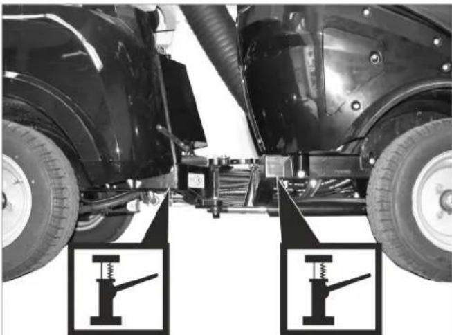
natural_image
Close-up of a car's front suspension system with two mechanical diagrams below (no text or symbols)Intake points for the jack
→ Loosen the wheel nuts/wheel bolts by about 1 revolution using a suitable tool.
→ Raise machine using vehicle jack.
→ Unscrew the wheel nuts/wheel bolts and remove them.
→ Remove wheel.
→ Have the defective wheel repaired by a specialised repair shop.
→ Place the wheel and screw in the wheel nuts/wheel bolts all the way; tighten them lightly.
→ Lower machine using vehicle jack.
→ Torque the wheel nuts/wheel bolts to the required torque.
| Tightening torque for front tyres 83 - 85 Nm | |
| Tightening torque for rear tyres 83 - 85 Nm |
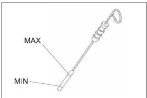
10.5.7 Check engine oil level and top up, if required
1 Oil cap (engine)
2 Oil dipstick
3 Oil filter
→ Pak the machine on an even surface.
→ Pull out oil dipstick.
→ Wipe off oil dipstick and insert.
→ Pull out oil dipstick.
→ Read the value of the oil level.
→ Insert the oil dip again.
- The oil level must lie between "MIN" and "MAX" marking.
- Add motor oil if the oil level is below the "MIN" marking.
- Do not fill oil above the "MAX" marking.
→ Remove oil cap.
→ Fill in motor oil.
Oil grade: Refer to chapter "Technical data"
→ Close oil cap.
→ Wait at least 5 minutes.
→ Check engine oil level.
CAUTION
An oil level that is too high leads to damages of the engine by overheating. If the oil level exceeds the "MAX" mark, oil must be drained until the correct oil fill level has been reached.
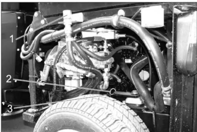
10.5.8 Change the motor oil and the oil filter
⚠Danger
Risk of burns due to hot oil or possible hot hose lines!
→ Ready a catch bin for appr. 6 litre oil.
→ Allow engine to cool down.
natural_image
Close-up of mechanical components with visible tubing and a numbered annotation (1), no readable text or symbols present.1 Oil drain screw
→ Unscrew oil drain plug.
→ Remove oil cap.
→ Drain off oil.
→ Unscrew the oil filter.
→ Clean the intake and sealing areas.
→ Coat the washer of the new oil filter with oil before fitting it.
→ Fit in the new oil filter and tighten it by hand.
→ Screw in the oil drain screw along with the new washer (torque to 60 Nm).
→ Fill in motor oil.
Oil grade: Refer to chapter "Technical data"
→ Close oil filler opening.
→ Let the motor run for approx. 30 seconds.
→ Check engine oil level.
→ Deliver the old oil to the respective collection centres.
10.5.9 Check hydraulic oil level and refill hydraulic oil
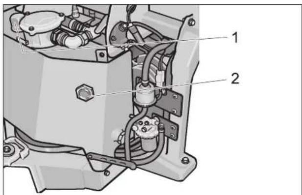
1 Cover
2 Oil sight glass
The oil level must be within the viewing glass.
→ Clean the lid and the surroundings.
→ Remove the lid.
→ Refill hydraulic oil.
Oil grade: Refer to chapter "Technical data"
10.5.10 Check hydraulic unit
→ Check all hydraulic hoses and connections and ensure that they are leak-proof.
Only Kärcher Customer Service is authorised to carry out maintenance tasks on the hydraulic unit.
10.5.11 Replace the hydraulic oil and filter
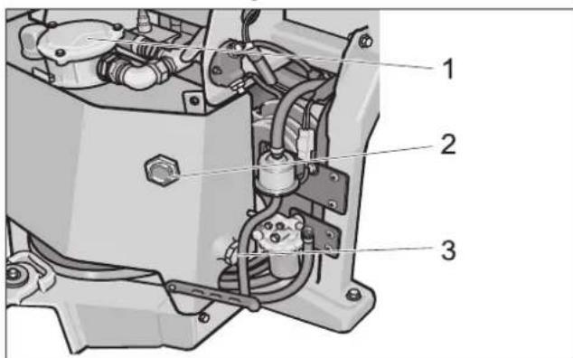
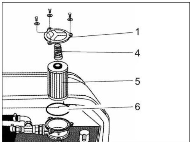
1 Cover
2 Oil sight glass
3 Oil drain screw
4 Spring
5 Filter inlay
6 Seal
→ Park the machine on an even surface.
→ Clean the lid and the surroundings.
→ Unscrew the screws and remove the lid.
→ Take out the spring and the filter insert.
→ Place the collection trough under the oil drain screw (approx. 20 litres capacity).
→ Unscrew the oil drain screw and collect oil.
→ Screw in the oil drain screw along with the new washer (torque to 40 Nm).
→ Fill the oil into the filler neck.
See "Specifications" for oil volume and type.
→ Insert the new hydraulic oil filter.
→ Check the seal and insert it.
→ Install the spring.
→ Replace the lid and tighten the screws.
→ Start the engine and let it run for a few minutes.
Check the oil drain screw and the lid for leaks.
→ Check the hydraulic oil level.
→ Deliver the old oil to the respective collection centres.
10.5.12 Change the oil in the wheel motors
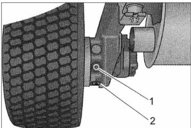
1 Oil fill screw
2 Oil drain screw
→ Clean the area around the oil fill screw and the oil drain screw.
→ Place the collection trough under the oil drain screw.
→ Unscrew the oil drain screw and collect oil.
→ Turn the oil fill screw out.
→ Fix in the oil drain screw and tighten it. (Torque 30 Nm).
→ Refill oil.
See "Specifications" for oil volume and type.
→ Screw in and tighten the oil filler screw. (Torque 30 Nm).
→ Deliver the old oil to the respective collection centres.
10.5.13 Check coolant level
→ Remove the right engine panel.
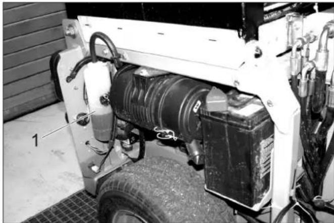
natural_image
Interior view of a vehicle charging station with battery, motors, and wiring (no visible text or symbols)1 Coolant expansion tank
The cooling water level must be checked while the engine is cooled off.
- The cooling water level must be at the lower marking.
10.5.14 Refill cooling water
- For coolant refer to chapter "Technical data"
- Use a water and antifreeze mixture to refill.
- Do not mix different antifreeze types.
- Use only soft water for the water and antifreeze mixture.
- Only top up coolant when the engine is cool.
→ Remove the right engine panel.
If the cooling water reservoir is completely empty, first fill up the radiator:
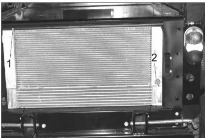
natural_image
Close-up of a heat exchanger or radiator component with labeled parts 1 and 2, no readable text or symbols beyond labels1 Radiator lid
2 Drain screw
→ Unscrew the radiator cap.
→ Fill the radiator slowly all the way to the top without bubbles.
→ Screw on the radiator lid.
Fill the cooling water equalising reservoir:
→ Remove the lid of the equalising reservoir.
→ Fill the equalising reservoir to the bottom mark.
→ Close the lid for the equalising reservoir.
→ Start the engine and let it warm up.
→ Check the filling level in the coolant expansion tank. While the engine is warm, the cooling water level must be at the top mark.
→ If the cooling water level is too low, shut the engine off, let it cool off and fill the missing cooling water volume into the cooling water equalising reservoir.
10.5.15 Check fuel filter
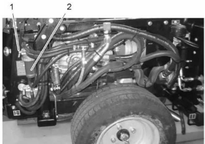
natural_image
Close-up of a vehicle's internal engine and wheel assembly, showing hoses and components (no visible text or symbols)1 Locking tap
2 Fuel filter
→ Ensure that the drain-off tap is open.
10.5.16 Replace the fuel filter
⚠Danger
Risk of explosion!
- Do not carry out maintenance tasks in closed rooms.
- Smoking and open flames must be strictly avoided.
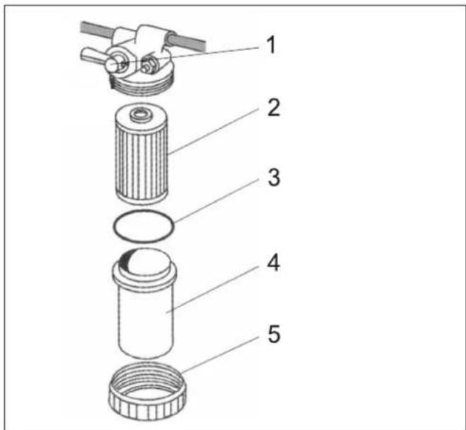
1 Locking tap
2 Filter inlay
3 O ring
4 Filter pot
5 Union joint
→ Close the stop valve.
→ Place the collection trough under the fuel filter.
→ Loosen the union joint.
→ Take out the filter inlay.
→ Clean the interior of the reservoir.
→ Insert a new filter insert.
→ Check the O-ring. Replace if necessary.
→ Reassemble the fuel filter.
→ Open locking tap.
→ Deaerate the fuel system
10.5.17 Check the water separator
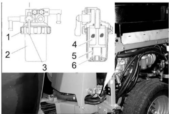
1 Union joint
2 Container
3 Locking tap
4 Wire filter
5 Float
6 Spring
→ Ensure that the drain-off tap is open.
→ Check whether the floater is located on the bottom of the water separator.
If the floater is not on the bottom, there is water in the water separator and the water separator must be cleaned.
10.5.18 Clean the water separator
⚠ Danger
Risk of explosion!
- Do not carry out maintenance tasks in closed rooms.
- Smoking and open flames must be strictly avoided.
→ Close the stop valve.
→ Place the collection trough under the water separator.
→ Loosen the union joint.
→ Remove the water separator reservoir.
→ Remove the spring and the floater from the reservoir.
→ Clean the interior of the reservoir.
→ Clean the wire filter.
→ Check the O-ring between the reservoir and the top part of the water separator.
→ Reassemble the water separator.
→ Open locking tap.
→ Deaerate the fuel system
10.5.19 Bleed the fuel system
CAUTION
Risk of damage. Do not ventilate the fuel system by activating the starter.
→ Check if the fuel tank is filled.
→ Open the drain tap on the fuel filter and on the water separator.
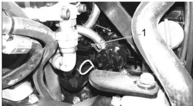
natural_image
Close-up of automotive engine components with hoses and valves (no visible text or symbols)1 Pump lever
→ Press the pump lever down several times until the fuel system is ventilated.
→ Start the motor.
→ If the engine does not start, repeat the ventilation process.
10.5.20 Check the air filter
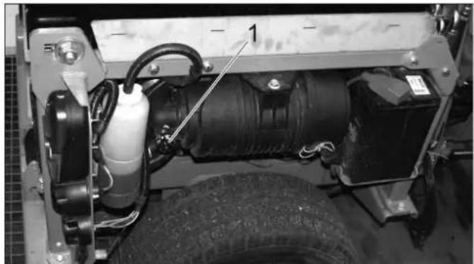
natural_image
Interior view of a vehicle's engine bay with visible tire, hoses, and battery (no text or symbols)1 Change air filter indicator
→ If the ventilation display is red, the air filter insert must be replaced.
10.5.21 Cleaning and replacing the air filter
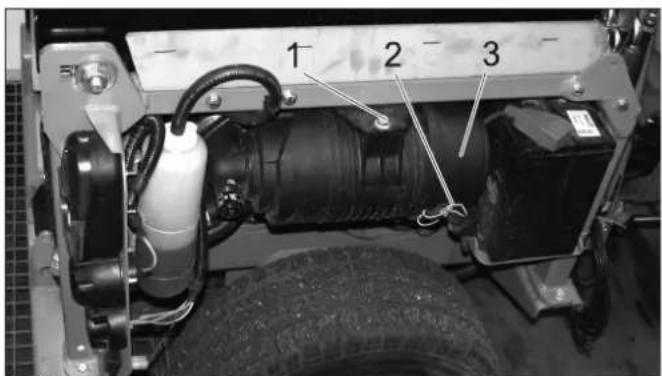
1 Screw
2 Clip
3 Air filter housing
→ Unscrew the screw.
→ Slide the air filter in and remove it toward the bottom.
→ Loosen the clamps.
→ Open the air filter casing.
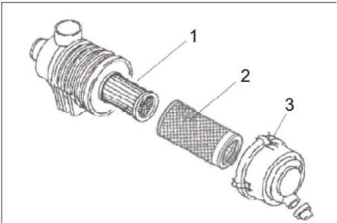
1 Air filter insert
2 Pre-filter
3 Clip
→ Remove pre-filter.
Leave the air filter insert in place and thus prevent the dust from entering the engine when cleaning the prefilter.
→ Carefully blow out the prefilter from the inside to the outside with compressed air (0.3...0.5 MPa).
→ If the prefilter does not become clean or if the prefilter is damaged, use a new prefilter.
→ Clean the interior of the air filter reservoir.
→ Replace air filter insert if necessary.
→ Reassemble air filter in the reverse sequence.
→ Press the key of the air filter display to reset the display.
10.5.22 Flush the water circulation system (option)
→ Disconnect the hose coupling of water circulation system.
→ Connect the water supply hose to the water circulation system and flush it.
→ When flushing the end toward the suction pipe, set the irrigation switch to water circulation system.
10.5.23 Lubricate the machine
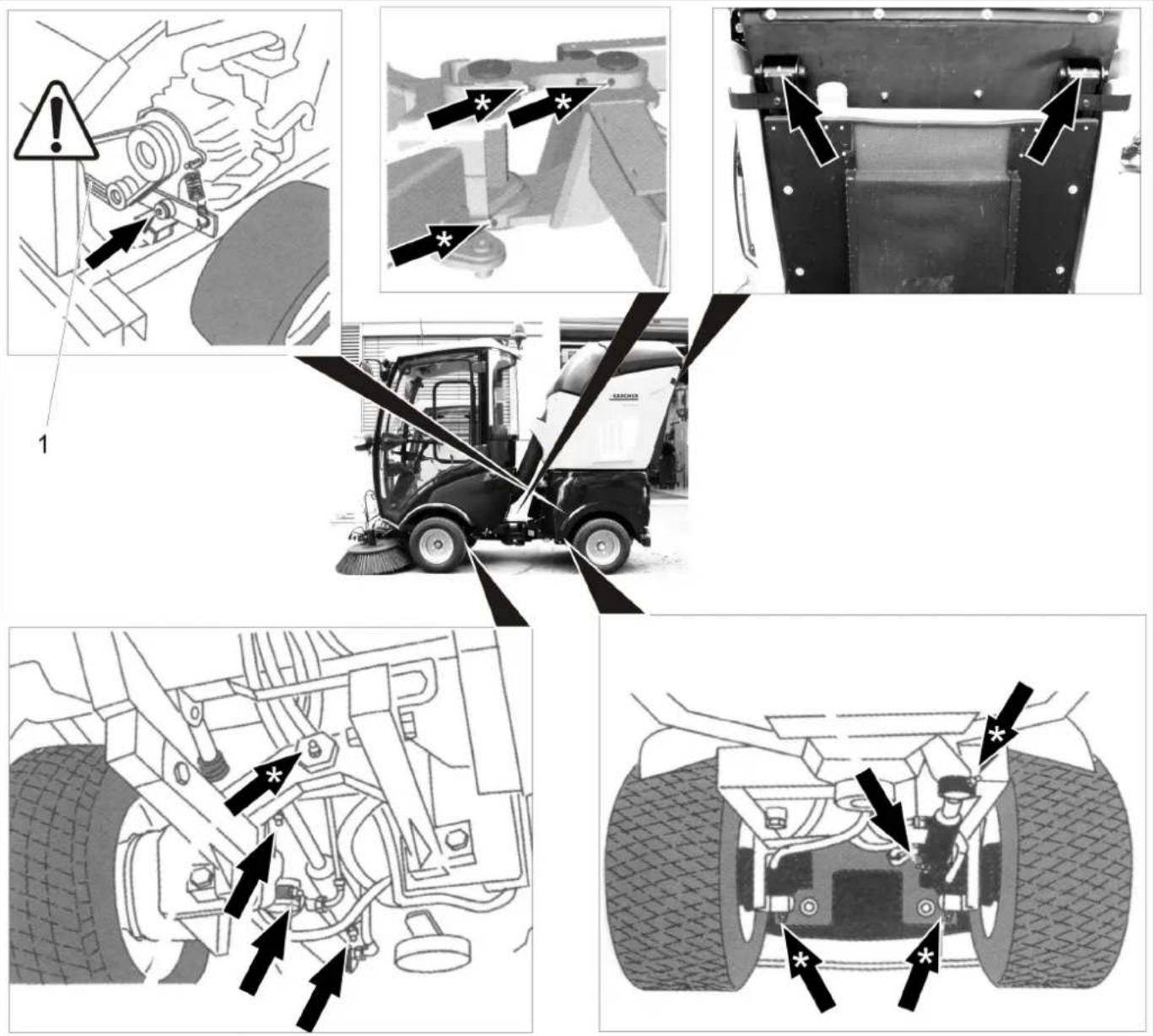
1 V - b e l t
CAUTION
Risk of functional disturbances. Do not let the V-belts get in contact with the grease.
→ Lubricate the grease nipples marked with an arrow with the grease gun.
→ Lubricate the grease nipples marked with "*" arrows prior to starting work daily.
→ Use high quality multi-purpose grease and use grease gun to lubricate.
10.5.24 Checking the V-Belt
Check the V-belts on the radiator fan of the engine.
10.5.25 Maintaining the wiper
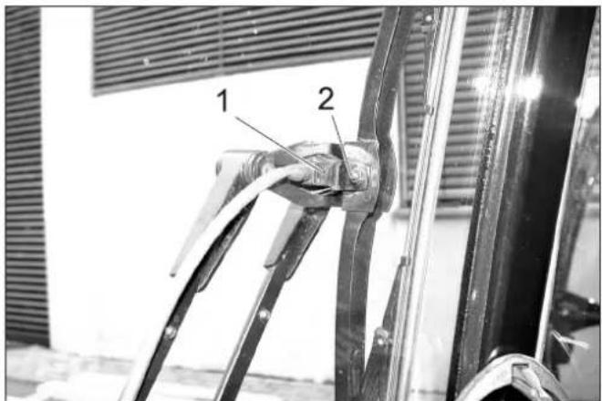
1 Spray nozzle
2 Screw
Clean/ set the spray nozzles:
→ Clean the spray nozzle openings using a wire.
→ Adjust the spraying direction by turning the spray head with a wire.
Change the wiper blades:
→ Loosen the screw.
→ Change the wiper blade.
10.5.26 Replace the side brush (for sweepers)
→ Lock parking brake.
→ The side-brushes lift up.
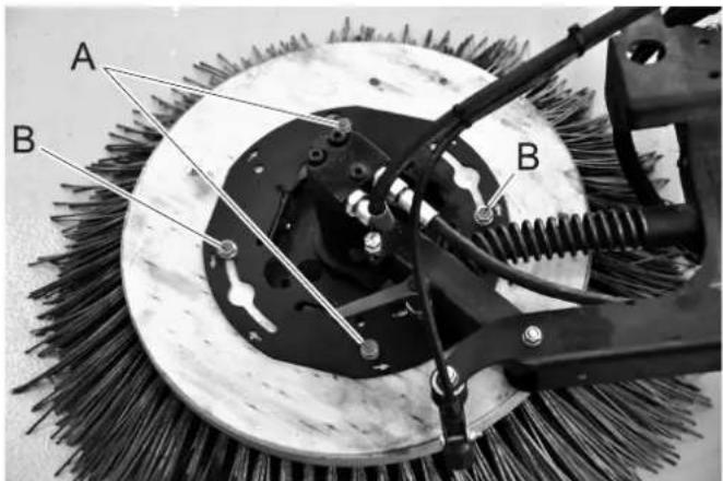
→ Unscrew screws "A".
→ Loosen screws "B".
→ Rotate the brush and remove it.
→ Screw two screws into the new brush offset by 180°.
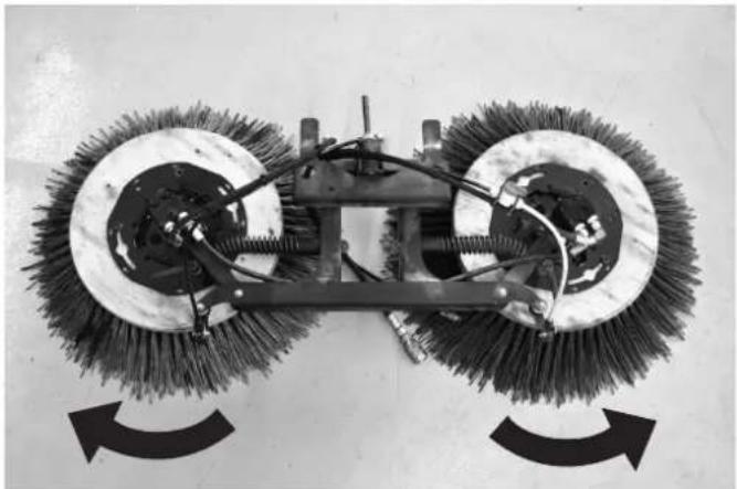
natural_image
Mechanical cleaning brush with two circular brushes and a central frame, shown with curved arrows indicating rotation (no text or symbols)→ Rotate the brush in the direction of the arrow.
→ Screw in the remaining screws and tighten them all.
10.5.27 Remove the sweeping unit (for sweepers).
→ Lower the brush.
→ Turn off the appliance.
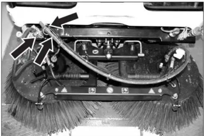
natural_image
Close-up of a cleaning or cleaning machine with visible brush and wiring (no text or symbols)→ Separate the couplings.
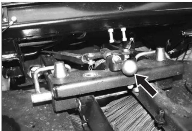
natural_image
Mechanical assembly diagram showing components like springs, bolts, and a knob with an arrow pointing to a specific part (no text or symbols present)→ Raise the brush manually and unhook the wire rope.
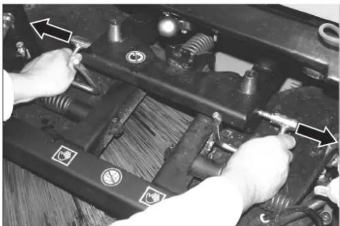
natural_image
Close-up of hands installing or adjusting mechanical components on a vehicle chassis (no visible text or symbols)→ Swing the safety pin forward and pull it out.
→ Lift off the sweeping system.
10.5.28 Ventilate the spray water system (for sweepers).
NOTICE
If the water tank was emptied completely, the spray water system must be bled after refilling.
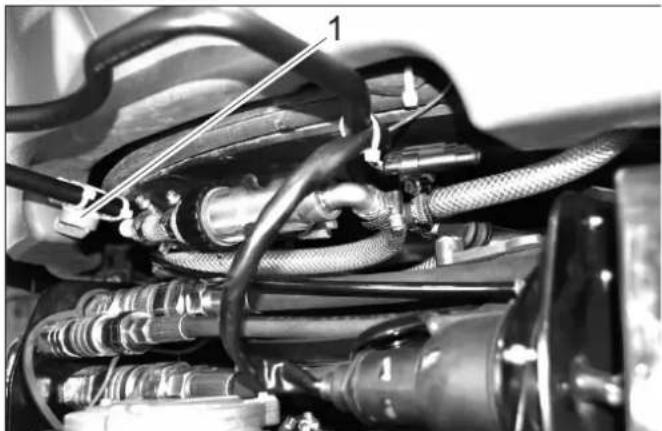
natural_image
Close-up of automotive engine components with hoses and hoses, no visible text or symbols1 V a l v e
→ Open the valve until bubble free water comes out.
→ Now close the valve.
10.5.29 Empty the water reservoir (for sweepers).
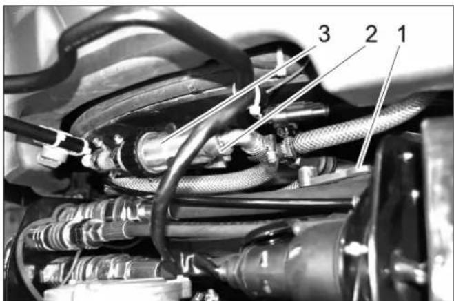
1 V a l v e
2 Union joint
3 Water filter
→ Close valve.
→ Unscrew the covering nut.
→ Pull out the hose.
→ Open valve.
→ Drain water.
→ Reattach the union joint to the filter and tighten it.
In case of danger of frost:
→ Open the valve and switch the brush water supply on for a few seconds.
→ Store the appliance with the valve open.
10.5.30 Clean the water filter (for sweepers)
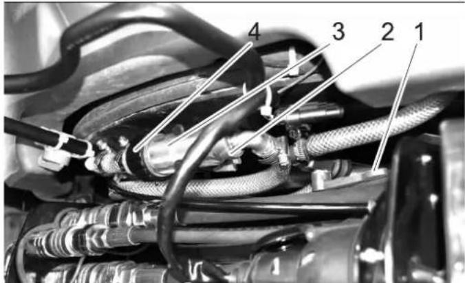
1 V a l v e
2 Union joint
3 Filter pot
4 Filter casing
→ Close valve.
→ Unscrew the covering nut.
→ Unscrew the filter cup from the filter casing.
→ Clean the filter inlay.
→ Open valve.
→ Install the filter cup on the filter casing and tighten it.
→ Reattach the union joint to the filter and tighten it.
→ Open valve.
10.5.31 Cleaning the spray nozzles on the side-brushes (for sweepers)

natural_image
Close-up of a cleaning brush on a surface with numbered annotations (1 and 2), no readable text or symbols beyond labels.1 Spray nozzle
2 Union joint
→ Unscrew the covering nut.
→ Pull out the spray nozzle.
→ Clean the spray nozzle.
10.5.32 Rinse the spray nozzles in the suction opening (for sweepers).
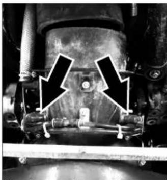
natural_image
Close-up of a mechanical assembly with two black arrows pointing to specific components (no visible text or symbols)
natural_image
Close-up of mechanical components with a white arrow pointing to a detail (no visible text or symbols)→ Lower the suction opening.
→ Pull the hose out of the holder toward the top.
→ Pull the nozzle holder out of the suction opening.
→ Pull out the spray nozzle.
→ Clean the spray nozzle.
Note:
Do not transpose the spray nozzles, the front nozzle has a different bore diameter.
10.5.33 Replace the suction opening rollers (for sweepers)
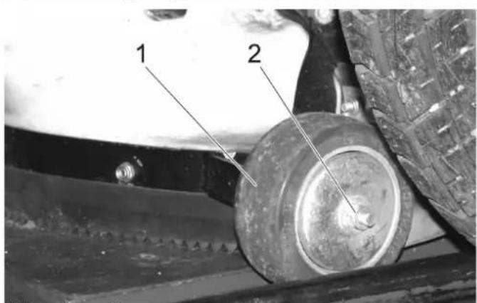
1 Running roller
2 Fastening nut
→ Remove the fastening nuts of the running rollers.
→ Replace the running rollers.
→ Replace the fastening nuts of the running rollers.
→ Adjust the running rollers in such a way that the suction lip has a floor clearance between 0 and 1 mm all around.
→ Tighten the fastening screws.
10.6 Fuses
NOTICE
Only use fuses with identical safety ratings.
→ Replace defective fuses.
10.6.1 Replacing the fuses in the fuse box in the driver cabin
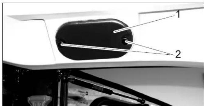
1 Cover
2 Knurled head screw
→ Unscrew the knurled screws and remove the cover.
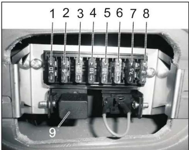
| Fuses driver's cab | ||
| 1 Free | switch location in the ceiling panel (second location from the right) | 10 A |
| 2 Car radio connection 3 A | ||
| 3 Working light 10 A | ||
| 4 Switch for option (e.g. heated outside mirrors) | 10 A | |
| 5 Wiper 10 A | ||
| 6 Windscreen washer system 3 A | ||
| 7 Overall lamp 7.5 A | ||
| 8 Cabin lighting 3 A | ||
| 9 Relay high beam | ||
10.6.2 Replacing the fuses in the fuse box of the motor compartment
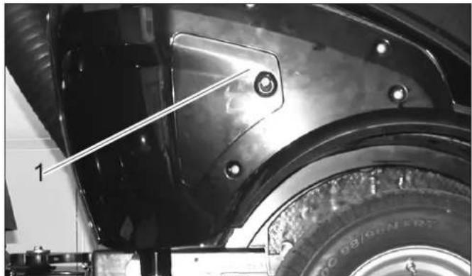
natural_image
Close-up of a car's front wheel and side panel, showing mounting hardware and tire assembly (no visible text or symbols)1 Cover
→ Remove the lid.
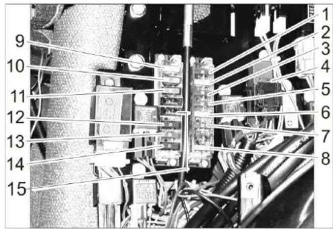
| Fuses motor compartment | ||
| 1 Indicator lamps, cooling water temperature buzzer, fuel pump, reverse horn, 7-way socket outlet front, 2-way socket outlet front, motor shutoff valve timer, motor shut-off valve (holding current) | 10 A | |
| 2 2-pin | socket front, 7-pin socket front, 2-pin socket rear, front light | 20 A |
| 3 Driving | direction valve, generator, 10 A | |
| 4 Air-conditioner | 7.5 A | |
| 5 Onboard | socket panel, 7-pin socket front 10 A | |
| 6 Motor | shutoff valve (inrush current) 30 A | |
| 7 Hour | meter for sweeping operation, PTO Stop, indicator lamp brake | 10 A |
| 8 Main | fuse 40 A | |
| 9 Dipped | beam 20 A | |
| 10 Air-conditioner | 20 A | |
| 11 Cabin | 30 A | |
| 12 Rotating beacon, horn, light relay, 7-way socket outlet front (pin 1) | 10 A | |
| 13 Blinker, hazard warning system | 10 A | |
| 14 Air-conditioner | 10 A | |
| 15 Comfort seat | 15 A | |
11 Troubleshooting
11.1 Faults with display
| DisplayWarning lamp for motor temperature lights up | CauseEngine is overheated | RemedySet the engine speed to idle. | By whomOperator |
| Check the level of cooling liquid in the engine.If the warning lamp does not turn off within 5 minutes, shut off the engine and contact Customer Service. | |||
| Warning lamp for hydraulic oil temperature | Hydraulic oil overheated | Temperature too high: Let the motor idle until the warning light is off.Switch off the working hydraulic. | Operator |
| Warning lamp for battery lights up | Battery is not being charged | Call Customer Service. | Operator |
11.2 Faults without display
| Fault Remedy | |
| Appliance cannot be started Charging or replacing | Battery |
| Press the brake pedal. | |
| Fill in fuel, deaerate the fuel system | |
| Clean or replace fuel filter | |
| Check fuel pipes, connections and joints and maintain them if required | |
| Inform Kärcher Customer Service. | |
| Engine is running erratically Clean or replace air | filter |
| Check fuel pipes, connections and joints and maintain them if required | |
| Inform Kärcher Customer Service. | |
| Engine is running but machine is only moving slowly or is not moving at all | Release parking brake |
| Check level of hydraulic fuel | |
| Inform Kärcher Customer Service. | |
| Side-brushes are rotating slowly or not at all (for sweepers) | Increase the side-brush speed |
| Remove ropes and tapes | |
| Check level of hydraulic fuel | |
| Inform Kärcher Customer Service. | |
| Appliances generates dust (for sweepers) Switch | on the water pump |
| Refill water | |
| Adjust the speed of the side-brushes | |
| Cleaning the spray nozzles on the side-brushes | |
| Inform Kärcher Customer Service. | |
| Sweeping unit does not pick up waste (for sweepers) | Reduce working area |
| Empty waste container | |
| Set the engine correctly | |
| Clean the suction channel | |
| Clean the exhaust grid | |
| Inform Kärcher Customer Service. | |
| Coarse waste is left behind (for sweepers) | Lower the suction opening and clean the top surface. |
| Waste container does not raise or lower (for sweepers) | Check level of hydraulic fuel |
| Inform Kärcher Customer Service. | |
| Operation problems with hydraulic movement parts | Inform Kärcher Customer Service. |
| One of two connected attachments is not be operated | Disconnect the hydraulic coupling of the attachment that will not be needed |
11.3 Towing
△CAUTION
Risk of damage. The appliance must not be towed. Do not move the sweeper at a speed higher than walking speed.
△DANGER
The vehicle is not approved for crane loading.
NOTICE
Make sure the brush system is not damaged while pushing (for sweepers).
→ Drain the spray water (for sweepers).
→ Empty the waste container (for sweepers).
→ Fasten the towing rope to the towing eye in the front or the rear.
→ Slowly drag the appliance onto the transport vehicle.
CAUTION
Risk of damage to the gear. Only push or pull the appliance slowly.
12 Technical specifications
| MC 50 | ||
| Drive speed, forward km/h 20 | ||
| Drive speed, reverse km/h 8 | ||
| Working speed km/h 10 | ||
| Climbing capability (max.) % 25 | ||
| Driven axles 2 | ||
| Theoretical surface cleaning performance m | ^2 /h 14000 | |
| Working width mm 1400 | ||
| Usage duration when tank is full h about 12 | ||
| Engine | ||
| Manufacturer -- Yanmar | ||
| Type | -- | 3TNV76-DU |
| Cylinder capacity | cm^3 | 1116 |
| Engine output at 3000 rpm | kW | 18.9 |
| Torque at 2000 1/min | Nm | 66.6 |
| Electrical system | ||
| Battery | V, Ah | 12, 40 |
| Fuel | ||
| Fuel type | Diesel | |
| Fuel tank capacity | I | 37 |
| Engine oil type | SAE 10W-40 | |
| Engine oil volume | I | 3.4 |
| Coolant (SAE J814C) | -- | Havoline XLC Antifreeze |
| Hydraulic oil type | Renol B HV 46 | |
| Hydraulic oil volume | I | 20 |
| Oil type of wheel motors GL4/5 75-W90 | ||
| Oil quantity, wheel motors | I | 4 x 0.08...0.09 |
| Waste container | ||
| Max. unloading height | mm 1400 | |
| Waste container volume (gross) | I ( m^3 ) | 700 (0,7) |
| Maximum load | kg | 565 |
| Side brushes | ||
| Side brush diameter | mm 700 | |
| Speed (continuous) | 1/min | 0...150 |
| Greases | ||
| For points to be lubricated manually | -- | Multi-purpose grease |
| Working conditions | ||
| Temperature | °C | -5 ... +40 |
| Air humidity, non-condensing | % 0 - 90 | |
| Dimensions and weights | ||
| Length x width x height | mm 2797 x 1212 x 1970 | |
| Transport weight | kg | 1150 |
| Permissible overall weight | kg | 1750 |
| Permissible front axle load | kg | 900 |
| Permissible rear axle load | kg | 1200 |
| Drawbar load of lorry hitch (Option) | kg | 120 |
| Drawing load of lorry hitch (Option), with/without brakes | kg | 1000/500 |
| Turning radius | mm 750 | |
| Water reservoir | I | 160 |
| Resulting values as per EN 60335-2-72 | ||
| Vibration total value on arms | m/ s^2 | <2.5 |
| Uncertainty K | m/ s^2 | 0.2 |
| Vibration total value on seat area | m/ s^2 | <0.5 |
| Uncertainty K m/s | MC 50 | |
| 2 | 0.1 | |
| Resulting values as per Outdoor2000/14/EG, with reference to EN 60335-2-72 | ||
| Sound pressure level L_pA | dB(A) 77 | |
| Uncertainty K_pA | dB(A) 3 | |
| Sound power level L_WA + Uncertainty K_WA | dB(A) 103 | |
* with sweeping unit
12.1 Tyres
CAUTION
Only use Kärcher-approved tyres.
| Tyre type Tyre size Re | commended | tyre pressure MPa (bar) |
| Road tyres 195/55 R10C | 0.62 (6.2) | |
| Grass tyres 20x10.00-10 | 0.28 (2.8) | |
| Standard tyres, extra wide | 20x12.00-10 | 0.14 (1.4) |
| Traction tyres (coarse tread) | 20x 8.00-10 | 0.45 (4.5) |
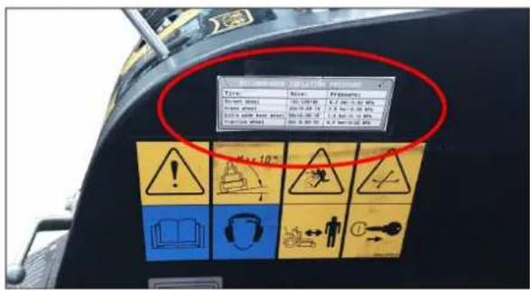
Figure: Label in the driver cabin with recommended tyre pressures
13 EU Declaration of Conformity
We hereby declare that the machine described below complies with the relevant basic safety and health requirements of the EU Directives, both in its basic design and construction as well as in the version put into circulation by us. This declaration shall cease to be valid if the machine is modified without our prior approval.
Product: Street Sweeper
Type: MC 50
Relevant EU Directives
2006/42/EC (+2009/127/EC)
2014/30/EU
2000/14/EC
Applied harmonized standards
EN 13019
CISPR 12
Applied conformity evaluation method
2000/14/EC: Appendix V
Sound power level dB(A)
Measured: 101
Guaranteed: 103
The signatories act on behalf of and with the authority of the company management.

H. Jenner
Chairman of the Board of Management

S. Reiser
Director Regulatory Affairs & Certification
Documentation supervisor:
S. Reiser
Alfred Kärcher SE & Co. KG
71364 Winnenden (Germany)
Tel.: +49 7195 14-0
Fax: +49 7195 14-2212
Winnenden, 2018/10/01
natural_image
Diagram of a cleaning or dust removal machine with a brush and conveyor belt, showing no text or symbols.natural_image
Close-up of a mechanical component with metallic plate and mounting bracket (no visible text or symbols)natural_image
Close-up of a metal wire crimping tool mounted on a wooden panel, with no visible text or symbols.natural_image
Close-up of a mechanical component with two white arrows pointing to specific areas (no text or symbols visible)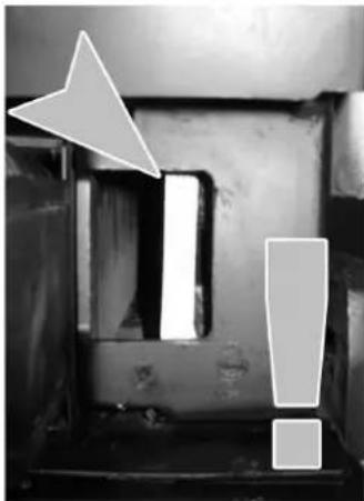
natural_image
Black-and-white photo of a mechanical component with warning symbols and an arrow pointing to a section (no readable text or labels)1 Coupleurs hydrauliques AUX2
2 Coupleurs hydrauliques AUX1
3 Coupleurs hydrauliques 2.PTO
5 Prise E1
6 Coupleurs hydrauliques Main PTO
7 Couplage de fuite
1 Prise E4 arrière, 7 pôles
2 Prise E3 arrière, 3 pôles
3 Coupleurs hydrauliques AUX2
4 Coupleurs hydrauliques 2.PTO
1 Coupleurs hydrauliques Main PTO
2 Coupleurs hydrauliques AUX2
3 Couplage de fuite
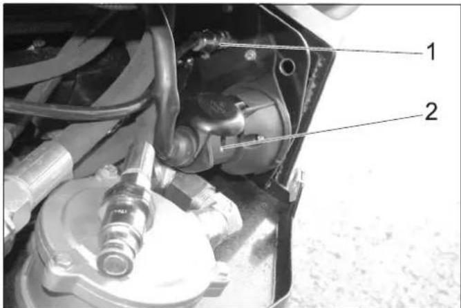
natural_image
Close-up of a mechanical device with labeled parts (1 and 2), showing internal components and no readable text or symbols.natural_image
Close-up of a mechanical assembly with metallic components and connecting rods (no visible text or symbols)1 Pédale de frein
natural_image
Mechanical assembly diagram showing two labeled parts (1 and 2) with no visible text or symbols1 Vis
2 Contre-écrou
1 Tôle de maintien
2 Soupape
natural_image
Black-and-white photo of a KEBCHER cleaning robotic vehicle with visible mechanical components and structural details (no text or symbols)natural_image
Close-up of a car's engine hose assembly with a downward arrow indicating compression (no text or symbols visible)natural_image
Close-up of mechanical connectors with textured surfaces and directional arrows indicating movement (no text or symbols)natural_image
Mechanical lift assembly with a tool holder and load mechanism, showing an arrow indicating direction (no text or symbols)⚠AVERTISSEMENT
Risque d'accident!
natural_image
Close-up of a mechanical component with a circular annotation and number 1, no readable text or symbols present.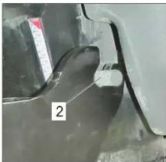
natural_image
Close-up of a metallic mechanical component with a numbered label '2' (no readable text or symbols beyond the number)natural_image
Mechanical assembly showing a white cylindrical rod mounted on a metal frame with two labeled components (1 and 2), no visible text or symbols.1 L e v i e r
2 Soupape
natural_image
Mechanical frame with a curved arrow indicating motion direction, no visible text or symbolsnatural_image
Close-up of a cleaning or cleaning robot with visible brush and wiring, no text or symbols presentnatural_image
Close-up of a vehicle's suspension system with hoses and sensors (no visible text or symbols)natural_image
Mechanical assembly diagram showing springs and connectors mounted on a vehicle chassis (no text or symbols visible)natural_image
Close-up of a cleaning brush with two large circular brushes mounted on a metal frame, no visible text or symbols.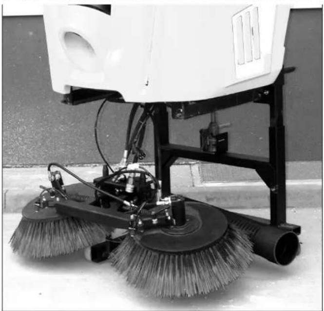
natural_image
Close-up of a white spray cleaning machine with multiple brush blades and wiring (no visible text or symbols)8 Outil rapporté
1 Porte-ressort
2 Support de protection
1 Support de protection
2 Tige de piston
natural_image
Close-up of a tractor's wheel and tire assembly with labeled parts (no text or symbols beyond labels)1 Rainure de fixation
2 Cône de centrage
natural_image
Top-down view of a vehicle's rear wheel assembly with labeled parts (no text or symbols beyond labels)1 Fermeture
natural_image
Close-up of a mechanical assembly with two vertical supports and a central shaft, showing no visible text or symbols.natural_image
Close-up of mechanical components with visible wiring and a numbered marker (1), no readable text or symbols present.1 Capot
2 Viseur d'huile

1 Capot
2 Viseur d'huile
natural_image
Interior view of a mechanical device with visible components and wiring (no text or symbols)natural_image
Close-up of a heat exchanger or radiator component with labeled parts 1 and 2, no readable text or symbols beyond labelsnatural_image
Close-up of a vehicle's internal engine and wheel assembly, showing hoses and components (no visible text or symbols)natural_image
Close-up of a mechanical assembly with hoses and components, no visible text or symbols1 Levier de pompe
natural_image
Interior view of a vehicle's engine bay with visible tire, hoses, and control panel (no text or symbols)1 Vis
2 Bride de fixation
natural_image
Mechanical cleaning or cleaning device with two circular brushes and a central hub, shown with curved arrows indicating rotation (no text or symbols)natural_image
Close-up of a cleaning or cleaning machine with visible brush and wiring (no text or symbols)natural_image
Mechanical assembly with pipes and a highlighted component (no visible text or symbols)natural_image
Close-up of hands adjusting mechanical components with directional arrows (no visible text or symbols)natural_image
Close-up of automotive engine components with hoses and hoses, no visible text or symbols1 Soupape
1 Soupape
1 Soupape
2 Écrou chapeau
3 Tasse de filtre
4 Boîtier du filtre
natural_image
Close-up of a cleaning or cleaning brush on a curved surface, with numbered annotations pointing to components (no readable text or symbols)natural_image
Close-up of a mechanical component with two black arrows pointing to features (no visible text or symbols)
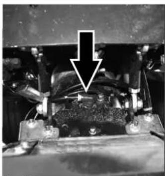
natural_image
Close-up of a mechanical assembly with a white arrow pointing to a component (no visible text or symbols)natural_image
Close-up of a car's front wheel and side panel with mounting holes, showing tire and mechanical components (no text or symbols visible)1 Capot
→ Retirer le couvercle.
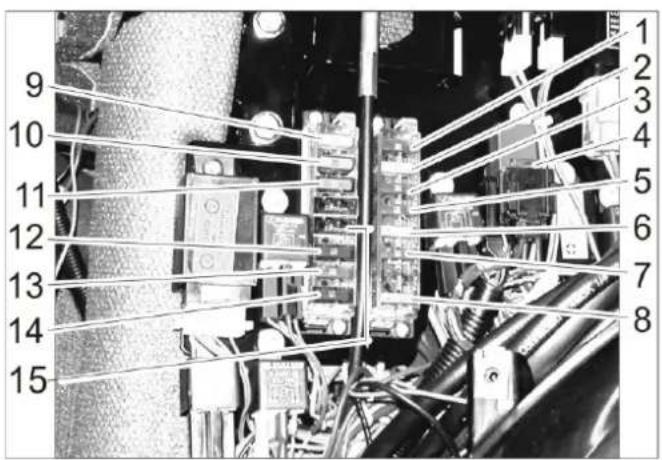
2006/42/CE (+2009/127/CE)
2014/30/UE
2000/14/CE

Chairman of the Board of Management

Director Regulatory Affairs & Certification
71364 Winnenden (Germany)
Tel.: +49 7195 14-0
Fax: +49 7195 14-2212
Winnenden, 2018/10/01
1 Indice
1 Indice 1
natural_image
Diagram of a cleaning or dust removal machine with visible brush and dust flow paths (no text or symbols)natural_image
Close-up of a metallic vehicle chassis with metal plates and bolts, no visible text or symbolsnatural_image
Close-up of a metal wire clamp or crimping tool mounted on a wooden panel, with no visible text or symbols.natural_image
Close-up of a mechanical component with two white arrows pointing to a rectangular cutout (no text or symbols visible)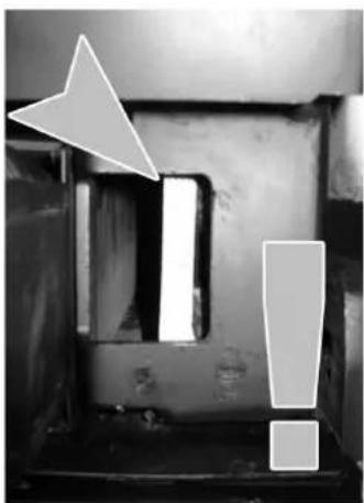
natural_image
Black-and-white photo of a mechanical component with an arrow pointing to a cutout and an exclamation mark (no text or symbols)natural_image
Close-up of a mechanical device with labeled parts (1 and 2), showing internal components and no readable text or symbols.1 V i t e
2 Controdado
natural_image
Black-and-white photo collage showing a Kirschler cleaning vehicle and its internal components (no visible text or symbols)natural_image
Close-up of a car fuel nozzle with a downward arrow pointing to the nozzle (no text or symbols visible)natural_image
Close-up of industrial hoses with white arrows indicating movement or assembly (no visible text or symbols)natural_image
Mechanical lift assembly with a tool holder and load mechanism, showing an arrow indicating direction (no text or symbols)⚠AVVERTIMENTO
natural_image
Close-up of a mechanical component with a circular annotation and number 1, no readable text or symbols present.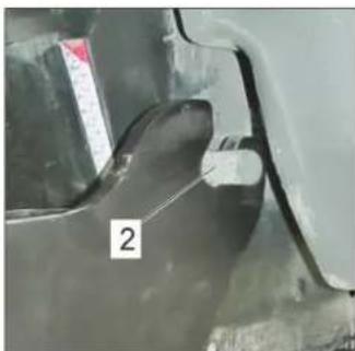
natural_image
Close-up of a metallic mechanical component with a labeled section '2' (no readable text or symbols beyond the label)natural_image
Mechanical assembly showing a rod inserted into a cylindrical component, with labeled parts 1 and 2 (no text or symbols on the main subject)1 L e v a
2 V a l v o l a
natural_image
Mechanical frame with a curved arrow indicating motion direction, no visible text or symbolsnatural_image
Close-up of a cleaning or cleaning robotic vehicle with visible brush and wiring, no text or symbols present.→ Sollevare manualmente le spazzole e sganciare la fune metallica.
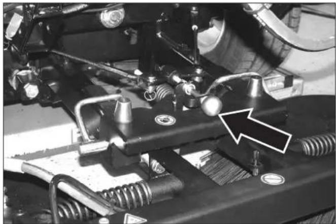
natural_image
Close-up of a vehicle's suspension system with hoses and sensors (no visible text or symbols)natural_image
Mechanical assembly diagram showing springs and connectors mounted on a vehicle chassis (no text or symbols visible)natural_image
Close-up of a cleaning brush with two large circular brushes mounted on a metal frame, no visible text or symbols.
natural_image
Close-up of a white spray cleaning machine with multiple brush blades and wiring (no visible text or symbols)1 Coppiglia
natural_image
Close-up of a tractor's wheel and tire assembly with labeled parts (no text or symbols beyond labels)1 Chiusura cofano
natural_image
Top-down view of a vehicle's rear wheel and chassis, showing structural components and tire alignment (no text or symbols)1 Chiusura
natural_image
Close-up of a car's lower suspension system with two mechanical diagrams below (no text or symbols)natural_image
Mechanical assembly diagram showing a vehicle's suspension system with labeled parts (no readable text or symbols)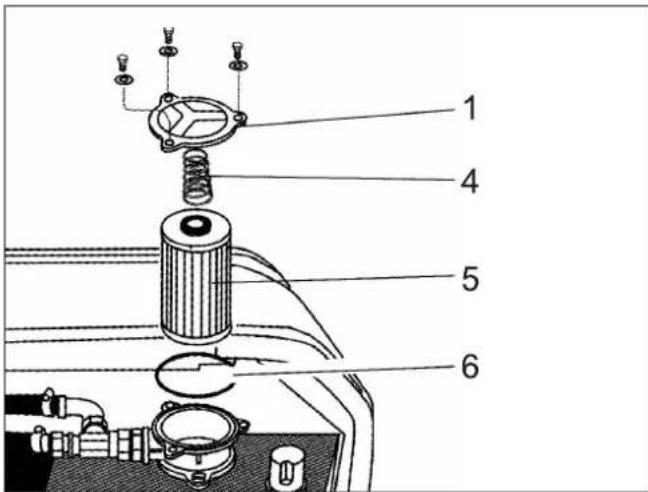
natural_image
Interior view of a mechanical device with visible components and wiring (no text or symbols)natural_image
Close-up of a heat exchanger or cooling unit with labeled parts (1 and 2), no readable text or symbols beyond labelsnatural_image
Close-up of a vehicle's internal components including hoses, tires, and suspension parts (no visible text or symbols)natural_image
Close-up of a mechanical engine component with hoses and valves (no visible text or symbols)1 Leva della pompa
natural_image
Interior view of a vehicle's engine bay with visible tire, hoses, and control panel (no text or symbols)natural_image
Mechanical cleaning brush with two circular brushes and a central frame, shown with curved arrows indicating rotation (no text or symbols)natural_image
Close-up of a cleaning or cleaning machine with visible brush and wiring (no text or symbols)natural_image
Mechanical assembly diagram showing a vehicle's mounting bracket with pipes and a directional arrow (no text or symbols)natural_image
Close-up of hands adjusting mechanical components with arrows pointing to specific parts (no visible text or symbols)natural_image
Close-up of automotive engine components with hoses and hoses, no visible text or symbols1 Val vol a
1 Val vol a
1 Val vol a
natural_image
Close-up of a cleaning or cleaning machine with labeled parts (1 and 2), showing brush and screw components on a surface (no readable text beyond labels)natural_image
Close-up of a mechanical assembly with two black arrows pointing to specific components (no visible text or symbols)
natural_image
Close-up of a mechanical assembly with a downward arrow pointing to a component (no visible text or symbols)1 Coperchio
2 Vite a testa zigrinata
natural_image
Close-up of a car's front wheel and side panel, showing mounting hardware and tire (no text or symbols visible)1 Coperchio
2006/42/CE (+2009/127/CE)
2014/30/UE
2000/14/CE
71364 Winnenden (Germany)
Tel.: +49 7195 14-0
Fax: +49 7195 14-2212
Winnenden, 2018/10/01
1 Inhoud
1 Inhoud 1
12.1 Bandenuitrusting 36
7 Vulopening schoonwaterreservoir
8 Diffusor
9 Peilindicatie schoon water
10 Oliepeilglas hydraulische olie
natural_image
Close-up of a mechanical assembly with metallic components and connecting rods (no visible text or symbols)natural_image
Close-up of a metal clamp or tool mounted on a wooden panel, with no visible text or symbols.1 Deurontgrendeling binnen
5.8 Veeggoedreservoir (veegmachine)
⚠ WAARSCHUWING
natural_image
Close-up of a mechanical component with two white arrows pointing downward (no text or symbols)
natural_image
Black-and-white photo of a mechanical component with warning symbols and an arrow pointing to a section (no readable text or labels)1 Contactdoos E4-achteraan, 7-polig
2 Contactdoos E3-achteraan, 3-polig
3 Hydraulische verbindingen AUX2
4 Hydraulische verbindingen 2.PTO
1 Reservoir ruitensproei-inrichting
2 Deksel
1 Hefboom stoelverstelling
2 Hoogteverstelling
natural_image
Close-up of a mechanical device with labeled parts (1 and 2), showing internal components like a lever, plug, and cable (no readable text or symbols beyond labels)1 Schroeven
2 Contramoer
natural_image
Exterior view of a Krencher cleaning or cleaning vehicle with visible brush and control panel (no text or symbols)
natural_image
Close-up of mechanical components with no visible text or symbols
natural_image
Close-up of a mechanical component with a tool and part, possibly a tool or tool, in operation (no visible text or symbols)
natural_image
Close-up of a car's air vent with a white arrow pointing to the nozzle and numbered annotation '1' (no text or symbols on the diagram itself)natural_image
Close-up of industrial pipe fittings with white arrows indicating movement or assembly (no text or symbols visible)7.8.4 Waterkoppelingen en elektrische steekverbindingen scheiden
→ Waterkoppeling scheiden.
→ Elektrische steekverbinding scheiden.
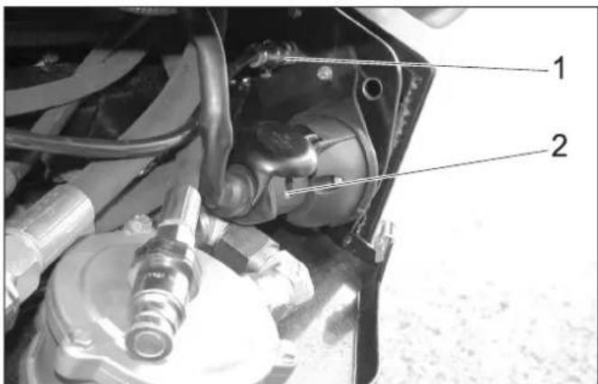
1 Wateraansluiting
2 Elektrische steekverbinding
natural_image
Side view of a white delivery truck with a hand架 (handrail) and a right-handled lever mechanism, no visible text or symbols.⚠ WAARSCHUWING
Ongevalgevaar!
natural_image
Close-up of a mechanical component with a circular annotation and number 1, no readable text or symbols present.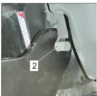
natural_image
Close-up of a metallic mechanical component with a numbered label '2' (no readable text or symbols beyond the number)natural_image
Mechanical assembly showing a white cylindrical rod mounted on a metal frame with two labeled components (1 and 2), no visible text or symbols.1 Hendel
2 Ventiel
natural_image
Mechanical frame with a white arrow indicating rotational motion, no visible text or symbolsnatural_image
Close-up of a cleaning or cleaning robot with visible brush and wiring, no text or symbols present.natural_image
Close-up of a mechanical assembly with hoses, springs, and a vehicle wheel (no visible text or symbols)natural_image
Mechanical assembly diagram showing springs and connectors mounted on a vehicle chassis (no text or symbols visible)natural_image
Close-up of a cleaning or broom with two large brush heads and visible wiring (no text or symbols)
natural_image
Close-up of a cleaning or cleaning tool with mounted brushes and a spray gun (no visible text or symbols)8 Aanbouwapparaat
8.1 Onkruidborstel
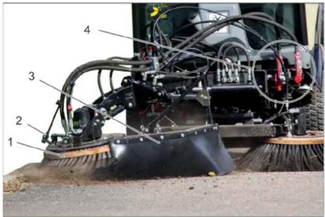
1 Onkruidborstel
2 Watersproeier
3 Spatbescherming
4 Hydraulische verbindingen PTO
natural_image
Close-up of industrial machinery with hoses and connectors (no visible text or symbols)1 Pen transportbeveiliging
2 Veerstekker
A Bedrijf
B Vervoer
1 Veerstekker
2 Zekeringssteun
natural_image
Side view of a vehicle's front wheel assembly with labeled parts (1 and 2), showing structural components without any readable text or symbols.natural_image
Close-up of a tractor's wheel and tire assembly with labeled parts (no text or symbols beyond labels)1 Kapsluiting
natural_image
Top-down view of a vehicle's rear wheel assembly with labeled parts (no text or symbols beyond labels)1 Sluiting
1 Bevestigingsstaaf
2 Koeler airconditioning (optie)
3 Combikoeler
Koelvloeistof is heet.
VOORZICHTIG
natural_image
Close-up of a car's lower leg and front wheel assembly with two mechanical diagrams below (no text or symbols)1 Olievuldeksel (motor)
2 Oliepeilstok
3 Oliefilter
natural_image
Close-up of mechanical components with visible wiring and a numbered annotation (1), no readable text or symbols present.1 Olie-aftapschroef

1 Deksel
2 Oliekijkglas
3 Olieaflaatschroef
4 Ve er
5 Filterelement
6 Afdichting
1 Olievulschroef
2 Olieaflaatschroef
natural_image
Close-up of a mechanical device with visible components and wiring, no readable text or symbols1 Koelmiddel-compensatievat
natural_image
Close-up of a heat exchanger or cooling unit with labeled parts (1 and 2), no readable text or symbols beyond labelsnatural_image
Undercarriage view of a vehicle showing hoses, tires, and mechanical components (no visible text or symbols)1 Afsluitkraan
2 Brandstofffilter
→ Garanderen dat de afsluitkraan open is.
10.5.16 Brandstofffilter vervangen
⚠Gevaar
Explosiegevaar!
1 Afsluitkraan
2 Filterelement
3 O - r i n g
4 Filterbeker
5 Wartelmoer
1 Wartelmoer
2 Container
3 Afsluitkraan
4 Draadfilter
5 V I o t t e r
6 Ve er
natural_image
Close-up of a mechanical engine component with hoses and springs (no visible text or symbols)1 Pomphendel
natural_image
Interior view of a vehicle's engine bay with tire, hoses, and battery (no visible text or symbols)1 Schroef
2 K I e m
3 Luchtfilterbehuizing
1 Luchtfilterinzet
2 Voorfilter
3 K I e m
1 V-snaar
VOORZICHTIG
natural_image
Mechanical cleaning or cleaning device with two circular brush heads and a central mechanical component, shown with curved arrows indicating rotation (no text or symbols present)natural_image
Close-up of a cleaning or cleaning machine with visible brush and wiring (no text or symbols)natural_image
Mechanical assembly with pipes and a ball, no visible text or symbolsnatural_image
Close-up of hands adjusting mechanical components with arrows pointing to specific parts (no visible text or symbols)natural_image
Close-up of automotive engine components with hoses and hoses, no visible text or symbols1 Ventiel
1 Ventiel
2 Wartelmoer
3 Waterfilter
1 Ventiel
2 Wartelmoer
3 Filterbeker
4 Filterhuis
natural_image
Close-up of a cleaning or cleaning machine with labeled parts (1 and 2), showing brush and screw components on a surface (no readable text or symbols beyond labels)1 Sproeier
2 Wartelmoer
natural_image
Close-up of a mechanical assembly with two black arrows pointing to specific components (no visible text or symbols)natural_image
Close-up of a mechanical assembly with a white arrow pointing to a component (no visible text or symbols)1 Deksel
2 Kartelschroef
natural_image
Close-up of a car's front wheel and side panel with mounting hardware (no visible text or symbols)1 Deksel
12.1 Bandenuitrusting
VOORZICHTIG

Chairman of the Board of Management

S. Reiser
Director Regulatory Affairs & Certification
71364 Winnenden (Germany)
natural_image
Diagram of a cleaning or dust removal machine with visible brush and dust flow paths (no text or symbols)natural_image
Close-up of a metallic mechanical component with textured surface and numbered parts (no readable text or symbols)natural_image
Close-up of a metal wire clamp or crimping tool mounted on a wooden panel, with no visible text or symbols.natural_image
Close-up of a mechanical component with two white arrows pointing to a rectangular cutout (no text or symbols visible)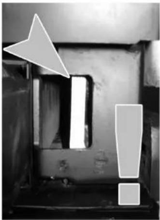
natural_image
Black-and-white photo of a mechanical component with warning symbols and an arrow pointing to a cutout (no readable text or labels)1 Acoplamientos hidráulicos Main PTO
2 Acoplamientos hidráulicos AUX2
3 Acoplamiento fugas
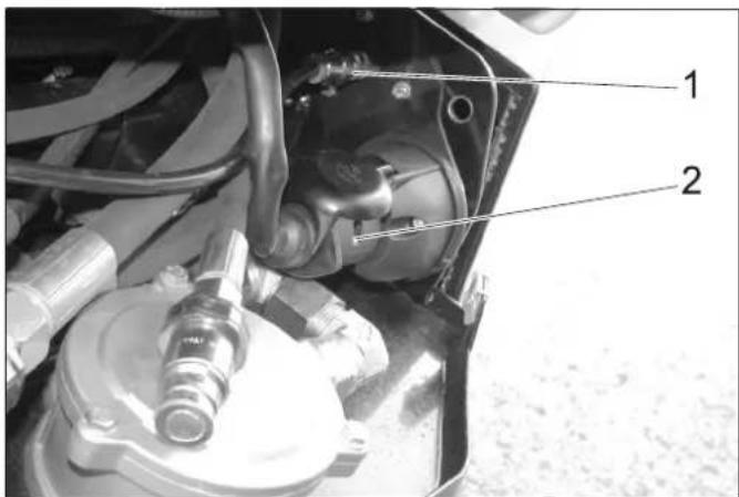
A Símbolo de filamento incadescente Precalentamiento
1 Recipiente limpiaparabrisas
2 T a p a
natural_image
Close-up of a mechanical device with labeled parts (1 and 2), showing internal components like a lever and plug assembly (no readable text or symbols)natural_image
Mechanical assembly with metal plate and mounting bracket, numbered 1 to 5 (no text or symbols on main structure)natural_image
Mechanical assembly diagram showing two labeled components (1 and 2) with no visible text or symbols1 Tornillo
2 Contratuerca
→ Aflojar la contratuerca.
AVISO
1 Chapa de sujeción
2 V á l v u l a
natural_image
Black-and-white photo of a Kürcher cleaning or cleaning vehicle with visible components and structural details (no text or symbols)natural_image
Close-up of a car fuel nozzle with a downward arrow pointing to a component, no visible text or symbolsnatural_image
Close-up of industrial hoses with visible internal threading and bolt holes, no text or symbols presentnatural_image
Mechanical assembly diagram showing a lift with tool and load, next to a truck (no text or symbols)ADVERTENCIA
natural_image
Close-up of a mechanical component with a circular annotation and number 1, no readable text or symbols present.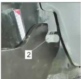
natural_image
Close-up of a metallic mechanical component with a numbered label '2' (no readable text or symbols beyond the number)natural_image
Mechanical assembly showing a white cylindrical rod mounted on a metal frame, with two labeled parts (1 and 2) indicating components.1 P a l a n c a
2 V á l v u l a
natural_image
Mechanical frame with a curved arrow indicating motion direction, no visible text or symbolsnatural_image
Close-up of a cleaning or cleaning robotic vehicle with visible brush and wiring, no text or symbols present.natural_image
Close-up of a mechanical assembly with hoses and components, no visible text or symbolsnatural_image
Mechanical assembly diagram showing hoses, springs, and a central component with directional arrows (no text or symbols)natural_image
Close-up of a cleaning brush with two large circular brushes mounted on a metal frame (no text or symbols visible)
natural_image
Close-up of a cleaning or cleaning tool with mounted brushes and a spray gun (no visible text or symbols)8 Aparato accesorio
natural_image
Close-up of a tractor's wheel and tire assembly with labeled parts (no text or symbols beyond labels)1 Cierre del capó
natural_image
Top-down view of a vehicle's rear wheel assembly with visible internal components and mounting brackets (no text or symbols)1 Cierre
natural_image
Close-up of a car's front suspension system with two mechanical components and a pressure relief symbol (no text or labels)natural_image
Mechanical assembly diagram showing a car suspension system with hoses and a tool (no text or symbols visible)1 T a p a
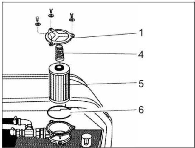
1 Tapa
natural_image
Interior view of an industrial machine with visible components and a numbered label (1), no readable text or symbols present.1 Recipiente compensador de refrigerante
natural_image
Close-up of a heat exchanger or cooling unit with labeled parts 1 and 2, showing internal heat distribution (no text beyond labels)1 Tapa del radiador
2 Tornillo de purga
natural_image
Undercarriage view of a vehicle showing hoses, tires, and mechanical components (no visible text or symbols)1 Grifo de cierre
2 Cartucho filtrante
3 Junta tórica
4 Taza del filtro
5 Tuerca de racor
natural_image
Close-up of automotive engine components including hoses and a valve (no visible text or symbols)natural_image
Mechanical assembly showing a motor, tire, and attached components (no visible text or symbols)1 Tornillo
2 G r a p a
1 Correa trapezoidal
PRECAUCIÓN
natural_image
Mechanical cleaning brush with two circular brushes and a central frame, showing directional arrows (no text or symbols)natural_image
Close-up of a cleaning or cleaning machine with visible brush and wiring (no text or symbols)natural_image
Mechanical assembly with pipes and a ball, no visible text or symbolsnatural_image
Close-up of hands installing or adjusting mechanical components on a vehicle chassis (no visible text or symbols)natural_image
Close-up of automotive engine components with hoses and hoses, no visible text or symbols1 V á l v u l a
1 V á l v u l a
1 V á l v u l a
2 Tuerca de racor
3 Taza del filtro
4 Carcasa del filtro
natural_image
Close-up of a cleaning or cleaning brush on a surface, showing components like a broom and screwdriver (no text or symbols visible)1 Boquilla pulverizadora
2 Tuerca de racor
natural_image
Close-up of a mechanical component with two black arrows pointing to features, no visible text or symbols.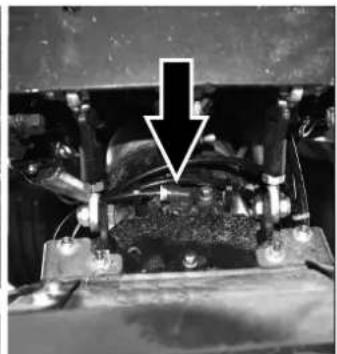
natural_image
Close-up of a mechanical component with a white arrow pointing to a specific part (no visible text or symbols)1 Tapa
natural_image
Close-up of a car's front wheel and side panel, showing mounting hardware and tire assembly (no visible text or symbols)1 T a p a
→ Extraiga la tapa.

2006/42/CE (+2009/127/CE)
2014/30/UE
2000/14/CE

Chairman of the Board of Management

Director Regulatory Affairs & Certification
71364 Winnenden (Germany)
Tel.: +49 7195 14-0
Fax: +49 7195 14-2212
Winnenden, 2018/10/01
1 Índice
1 Índice 1
natural_image
Diagram of a cleaning or dust removal machine with visible brush and dust flow paths (no text or symbols)natural_image
Close-up of a metallic vehicle chassis with visible structural components and numbered parts (no text or symbols)natural_image
Close-up of a mechanical clamp or bracket with a numbered label pointing to a component (no readable text or symbols)natural_image
Close-up of a mechanical component with two white arrows pointing downward (no text or symbols)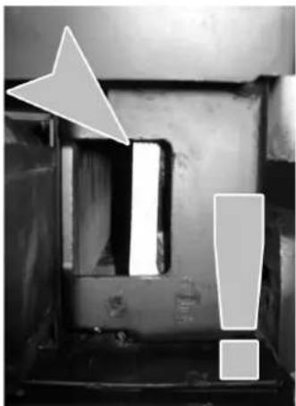
natural_image
Black-and-white photo of a mechanical component with warning symbols and an arrow pointing to a cutout (no readable text or labels)natural_image
Close-up of a mechanical device's internal components, showing a lever and keyway (no text or symbols visible)natural_image
Close-up of a metallic vehicle chassis with metal plates and mounting brackets (no visible text or symbols)1 Parafuso
2 Contraporca
→ Desapertar a contraporca.
AVISO
1 Chapa de suporte
2 V á l v u l a
natural_image
Black-and-white photo collage showing a Kürcher cleaning vehicle and its internal components (no visible text or symbols)natural_image
Close-up of a car's air duct system with a downward arrow and numbered annotation (1), no readable text or symbols present.7.8.3 Separar os acoplamentos hidráulicos CUIDADO
natural_image
Close-up of mechanical connectors with white arrows indicating movement or force direction (no text or symbols visible)natural_image
Mechanical lift assembly with a tool holder and load mechanism, showing a rightward motion indicator (no text or symbols)ATENÇÃO
Perigo de acidente!
natural_image
Close-up of a mechanical component with a circular annotation and number 1, no readable text or symbols present.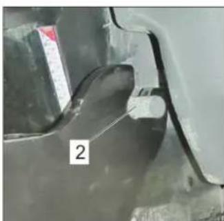
natural_image
Close-up of a metallic mechanical component with a labeled section '2' (no readable text or symbols beyond the number)natural_image
Mechanical assembly showing a white cylindrical rod mounted on a metal frame with two labeled components (1 and 2), no visible text or symbols.1 Alavanca
2 V á l v u l a
natural_image
Mechanical frame with a curved arrow indicating motion direction, no visible text or symbolsnatural_image
Close-up of a cleaning or cleaning robotic vehicle with visible brush and wiring, no text or symbols present.natural_image
Close-up of a mechanical assembly with hoses and components, no visible text or symbolsnatural_image
Mechanical assembly diagram showing springs, hoses, and connectors (no text or symbols visible)natural_image
Close-up of a cleaning or broom with two large brush heads and visible wiring (no text or symbols)
natural_image
Close-up of a cleaning or cleaning brush with visible brushwork and wiring (no text or symbols)8 Acessório
1 Ficha de mola
1 Barra de fixação
10.5.6 Mudar as rodas
⚠️Perigo
natural_image
Close-up of a car's front suspension system with two mechanical components and a pressure relief symbol (no text or labels)Ponto de encaixe para o macaco
natural_image
Mechanical assembly diagram showing a car suspension system with hoses and components (no visible text or labels)1 Tampa

1 Tampa
natural_image
Interior view of a mechanical device with hoses and a battery, labeled with number 1 (no visible text or symbols)natural_image
Close-up of a heat exchanger or cooling unit with labeled parts (1 and 2), no readable text or symbols beyond labels1 Tampa do radiador
2 Parafuso de purga
natural_image
Close-up of a vehicle's internal components including hoses, springs, and a tire (no visible text or symbols)1 Porca de capa
2 Recipientes
natural_image
Close-up of a mechanical engine component with hoses and valves (no visible text or symbols)1 Alavanca da bomba
natural_image
Interior view of a vehicle's engine bay with visible tire, hoses, and mechanical components (no text or symbols)1 Parafuso
2 Grampo
1 Elemento do filtro de ar
2 Pré-filtro
3 Grampo
→ Retirar o pré-filtro.
Deixar o elemento filtrante do ar montado, para evitar que o pó entre no motor, durante a limpeza do pré-filtro.
1 Correia trapezoidal
CUIDADO
natural_image
Mechanical cleaning or cleaning device with two circular brush heads and a central mechanical component, shown with curved arrows indicating rotation (no text or symbols visible)natural_image
Close-up of a cleaning or cleaning device with visible brush and wiring (no text or symbols)natural_image
Mechanical assembly with pipes and a ball, no visible text or symbols→ Levantar manualmente a vassoura e desengatar o cabo de arame.
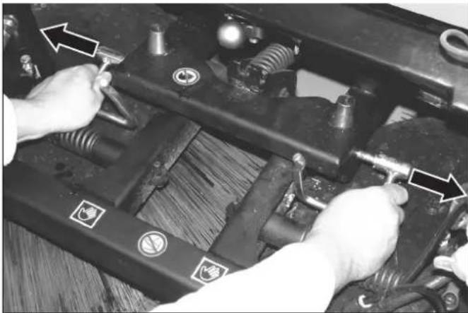
natural_image
Close-up of hands performing maintenance on a mechanical assembly with tools and components (no visible text or symbols)natural_image
Close-up of automotive engine components with hoses and hoses, no visible text or symbols1 V á l v u l a
1 V á l v u l a
1 V á l v u l a
natural_image
Close-up of a cleaning or cleaning brush on a surface, showing components like a brush head and bolts (no text or symbols visible)1 Bico pulverizador
2 Porca de capa
→ Desenroscar a porca de capa.
→ Retirar o bico pulverizador.
→ Limpar o bico pulverizador.
natural_image
Close-up of a mechanical component with two black arrows pointing to features, no visible text or symbols.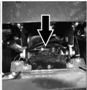
natural_image
Close-up of a mechanical component with a downward arrow pointing to a specific part (no visible text or symbols)1 Tampa
natural_image
Close-up of a car's front wheel and side panel, showing mounting hardware and tire assembly (no text or symbols visible)1 Tampa Retirar a tampa.
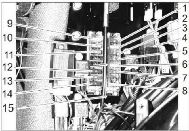
2006/42/CE (+2009/127/CE)
2014/30/UE
2000/14/CE

Chairman of the Board of Management

Director Regulatory Affairs & Certification
71364 Winnenden (Germany)
Tel.: +49 7195 14-0
Fax: +49 7195 14-2212
Winnenden, 2018/10/01
natural_image
Diagram of a cleaning or dust removal machine with a brush and fan blade, showing airflow direction (no text or symbols)natural_image
Close-up of a mechanical assembly with metallic components and connecting rods (no visible text or symbols)natural_image
Close-up of a metal clamp or tool mounted on a wooden panel, with no visible text or symbols.natural_image
Close-up of a mechanical component with two white arrows pointing downward (no text or symbols)
natural_image
Black-and-white photo of a mechanical component with warning symbols and an arrow pointing to a section (no readable text or labels)natural_image
Close-up of a mechanical device with labeled parts (1 and 2), showing internal components and no readable text or symbols.natural_image
Close-up of a mechanical assembly with metallic components and connecting rods (no visible text or symbols)1 Πεντάλ φρένου
1 B í δ α
2 Αντίπερικόχλιο
natural_image
Black-and-white photo of a KARCHER robotic cleaning vehicle with visible brush and control panel, plus close-up insets showing mechanical components (no text or symbols)natural_image
Mechanical assembly showing a white cylindrical rod mounted on a metal frame with two labeled components (1 and 2), no visible text or symbols.1 μοχλός
2 B α λ β í δ α
natural_image
Mechanical frame with a curved arrow indicating motion direction, no visible text or symbolsnatural_image
Close-up of a cleaning or cleaning robot with visible brush and wiring, no text or symbols present.natural_image
Close-up of a mechanical vehicle suspension system with hoses and sensors (no visible text or symbols)natural_image
Mechanical assembly diagram showing springs and bolts mounted on a vehicle chassis (no text or symbols visible)natural_image
Close-up of a cleaning or broom with two large brush heads and visible wiring (no text or symbols)
natural_image
Close-up of a cleaning or cleaning brush with visible brushwork and wiring (no text or symbols)8 Πρόσθετη συσκευή
8.1 Σκούπα ζιζανίων
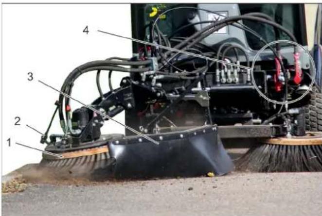
natural_image
Close-up of industrial machinery with coiled cables and connectors (no visible text or symbols)natural_image
Close-up of a tractor's wheel and tire assembly with labeled parts (no text or symbols beyond labels)1 Ασφάλεια καπακιού
natural_image
Top-down view of a vehicle's rear wheel assembly with visible components and mounting brackets (no text or symbols)1 M á v τ α λ o
1 Ράβδος στερέωσης
natural_image
Close-up of a car's front suspension system with two mechanical diagrams below (no text or symbols)natural_image
Close-up of mechanical components with visible wiring and a numbered label (1), no readable text or symbols present.1 Κάλυμμα

1 Κάλυμμα
natural_image
Interior view of a mechanical device with hoses and a battery, no visible text or symbolsnatural_image
Close-up of a heat exchanger or radiator component with labeled parts (1 and 2), no readable text or symbols beyond labels.1 Καπάκι ψυγείου
2 B í δ α ε κ ρ ο ής
natural_image
Interior view of a vehicle's undercarriage showing hoses, tires, and structural components (no visible text or symbols)1 P α κ ό ρ
2 K á ð o ς
natural_image
Close-up of mechanical components with hoses and a numbered label (1), no readable text or symbols beyond the label.natural_image
Interior view of a vehicle's lower body showing engine, tire, and hoses (no visible text or symbols)1 Φ í λ τ ρ ο α έ ρ α
2 Προφίλτρο
3 Σ φιγκτήρας
natural_image
Mechanical cleaning or cleaning device with two circular brushes and a central frame, shown with curved arrows indicating rotation (no text or symbols)natural_image
Close-up of a cleaning or cleaning machine with visible brush and wiring (no text or symbols)natural_image
Mechanical assembly diagram showing a vehicle's suspension system with pipes and tools (no text or labels visible)natural_image
Close-up of hands installing or adjusting mechanical components on a vehicle chassis (no visible text or symbols)natural_image
Close-up of automotive engine components with hoses and hoses, no visible text or symbols1 B α λ β í δ α
2 P α κ ό ρ
3 Θήκη φίλτρου
4 Περίβλημα φίλτρου
natural_image
Close-up of a cleaning brush head with labeled parts (1 and 2), no readable text or symbols beyond labelsnatural_image
Close-up of a mechanical component with two black arrows pointing to features, no visible text or symbols.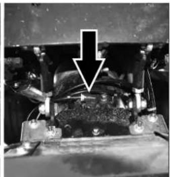
natural_image
Close-up of electrical components with a downward arrow pointing to a component (no visible text or symbols)1 Κάλυμμα
2 Ρικνωτός κοχλίας
natural_image
Close-up of a car's front wheel and side panel, showing mounting hardware and tire assembly (no visible text or symbols)1 Κάλυμμα
71364 Winnenden (Germany)
Tel.: +49 7195 14-0
Fax: +49 7195 14-2212
Winnenden, 2018/10/01

natural_image
Black silhouette of a hand giving a thumbs-up gesture (no text or symbols)THANK YOU!
MERCI! DANKE! iGRACIAS!
Registrieren Sie Ihr Produkt und profitieren Sie von vielen Vorteilen. Register your product and benefit from many advantages. Enregistrez votre produit et bénéficier de nombreux avantages. Registre su producto y aproveche de muchas ventajas.
www.kaercher.com/welcome

Bewerten Sie Ihr Produkt und sagen Sie uns Ihre Meinung. Rate your product and tell us your opinion. Évaluer votre produit et dites-nous votre opinion. Reseñe su producto y díganos su opinión.

natural_image
Icon showing a gear and wrench, no text or symbols presentwww.kaercher.com/dealersearch
Alfred Kärcher SE & Co. KG
Alfred-Kärcher-Str. 28-40
71364 Winnenden (Germany)
Tel.: +49 7195 14-0
Fax: +49 7195 14-2212