MC 250 STAGE V - Sweeper Kärcher - Free user manual and instructions
Find the device manual for free MC 250 STAGE V Kärcher in PDF.

User questions about MC 250 STAGE V Kärcher
0 question about this device. Answer the ones you know or ask your own.
Ask a new question about this device
Download the instructions for your Sweeper in PDF format for free! Find your manual MC 250 STAGE V - Kärcher and take your electronic device back in hand. On this page are published all the documents necessary for the use of your device. MC 250 STAGE V by Kärcher.
USER MANUAL MC 250 STAGE V Kärcher
Variante Lenkung links
| F1 fuse MINI 15A hazard light, brake light 6.844-809.0 |
| F2 fuse MINI 10A position lamps, interior lamp 6.844-808.0 |
| F3 fuse MINI 10A spray pump 6.844-808.0 |
| F4 fuse MINI 30A screen heater 6.844-042.0 |
| F6 fuse MINI 5A fog lamp (option) 6.844-806.0 |
| F7 fuse MINI 5A position lamps left 6.844-806.0 |
| F8 fuse MINI 5A position lamps right 6.844-806.0 |
| F9 fuse MINI 10A wiper 6.844-808.0 |
| F10 fuse MINI 7.5A radio 6.844-807.0 |
| F11 fuse MINI 10A indicator 6.844-808.0 |
| F12 fuse MINI 15A beacon lamps 6.844-809.0 |
| F13 fuse MINI 5A display, rear camera 6.844-806.0 |
| F14 fuse MINI 5A BODAS ecu work hydraulics 6.844-806.0 |
| F15 fuse MINI 5A engine 6.844-806.0 |
| F17 fuse MINI 15A head lamps 6.844-809.0 |
| F18 fuse MINI 15A work lamps front 6.844-809.0 |
| F19 fuse MINI 15A cabin fan 6.844-809.0 |
| F20 fuse MINI 10A mirror heater 6.844-808.0 |
| F21 fuse MINI 10A compressor seat 6.844-808.0 |
| F22 fuse MINI 15A cabin accessairs 6.844-809.0 |
| F23 fuse MINI 20A implement connector 6.844-043.0 |
| F24 fuse MINI 7.5A implement Aux 6.844-807.0 |
Hinweis
| F25 fuse MINI | 10A | engine ecu | 6.644-608.0 |
| F26 fuse MINI | 15A | engine ecu | 6.644-609.0 |
| F27 fuse MINI | 15A | engine | 6.644-609.0 |
| F28 fuse MINI | 15A | ATS (PM sensor B67) | 6.644-609.0 |
| F29 fuse MINI | 10A | ATS (NOx sensor B64) | 6.644-608.0 |
| F30 fuse MINI | 10A | ATS (NOx sensor B65) | 6.644-608.0 |
| F33 fuse MINI | 5A | radio | 6.644-606.0 |
| F34 fuse MINI | 10A | SCR (Adblue pump supply) | 6.644-608.0 |
| F35 fuse MINI | 5A | SCR | 6.644-606.0 |
| F38 fuse MINI | 5A | SCR Adblue sensor B66 | 6.644-606.0 |
| F37 fuse MINI | 20A | fuel filter heater | 6.644-043.0 |
| F38 fuse MINI | 20A | BODAS ecu drive hydraulics | 6.644-043.0 |
| F39 fuse MINI | 5A | BODAS ecu drive hydraulics | 6.644-606.0 |
| F40 fuse MINI | 5A | BODAS ecu work hydraulics | 6.644-606.0 |
| F41 fuse MAXI | 30A | BODAS ecu work hydraulics A1 | 6.644-042.0 |
| F42 fuse MAXI | 60A | glow plugs | 6.644-277.0 |
| F51 fuse MIDI | 80A | main | 7.644-031.0 |
Hinweis
1.2 Scope of delivery 42
1.2.1 Checking the delivery 42
1.2.2 MC 250 scope of delivery 42
1.2.3 Exhaust Gas Treatment System (ATS). 42
1.3 Warranty 42
1.4 Accessories and spare parts 42
2 Intended use 42
2.1 Device carrier 42
2.2 Foreseeable misuse 43
3 Environmental protection 43
3.1 Disposal 43
3.2 Disposal of the worn out vehicle 43
4 Safety information 43
4.1 Hazard levels 43
4.2 General safety instructions 43
4.3 Safety instructions for driving 43
4.4 Diesel engine safety instructions 43
4.5 Safety instructions for transportation 43
4.6 Safety instructions for care and maintenance 43
4.7 Additional operating safety instructions 44
4.8 Position of factory nameplates 44
4.9 Chassis number position (VIN) 44
4.10 Symbols on the vehicle 45
4.11 Position of the symbols on the vehicle 46
4.12 Safety devices 46
4.12.1 Start inhibitor 46
4.12.2 Seat contact switch 46
4.12.3 Parking brake 46
4.12.4 Driver cabin 46
5 Batteries / chargers 47
5.0.1 Warning symbols 47
5.0.2 Safety instructions 47
6 Vehicle overview 48
6.1 Front view 48
6.2 Rear view 48
6.3 Hydraulic connections 48
6.3.1 Front hydraulic connections 48
6.3.2 Rear hydraulic connections 49
6.4 Panels 49
7 Driver cabin 49
7.1 Doors 49
7.2 Interior filter 50
7.3 Radio 50
7.4 Switch panel 50
7.5 Heating, ventilation, air-conditioner 50
7.5.1 Automatic air-conditioner (optional) 51
7.6 Interior lighting 51
7.7 Sun visor 51
7.8 Console at the driver's seat 52
7.8.1 Battery disconnector relay switch 52
7.9 Steering wheel panel 52
7.9.1 Multi-function switch 52
7.9.2 Travel direction selector switch 53
7.9.3 Ignition lock 53
7.10 Pedals 53
7.10.1 Accelerator pedal 53
7.10.2 Brake pedal 53
7.10.3 Parking brake 53
7.11 Display 54
7.11.1 Function buttons/setting buttons 54
7.11.2 Display indicators in start/transport mode 54
7.11.3 Working mode displays 54
7.11.4 Select steering (2-wheel / 4-wheel) 55
7.11.5 Reversing camera 55
7.11.6 Bridging the seat contact switch 55
7.11.7 Symbols on the display 55
4 Operating consoles 57
4.1 Arm rest control panel 57
4.1.1 Device carrier control assignments.. 57
5 Display 58
5.1 Attachments menu 58
5.2 Settings menu 58
5.2.1 Making display settings 59
5.2.2 Display system information 59
5.2.3 DPF (Diesel particle filter) 59
5.3 Service menu 60
5.4 AUX menu (depressurize the hydraulic system) 60
6 Initial startup 60
6.1 Safety checks before startup 60
6.1.1 Device carrier safety check 60
6.2 Setting the driver's seat 60
6.3 Setting the steering wheel position 61
6.4 Refuelling 62
6.4.1 Refuelling 62
6.4.2 Fill DEF or AdBlue 62
7 Operation 62
7.1 During the first 10/50/100 operating hours (running-in period) 62
7.2 Parking brake 62
7.3 Drive mode 62
7.3.1 Start the engine 62
7.3.2 Selecting the travel direction 63
7.3.3 Driving 63
7.3.4 Stopping 63
7.3.5 Differential lock (special option) 63
7.3.6 Tempomat 63
7.3.7 Parking the vehicle 64
7.4 Regeneration process for vehicles with a diesel particle filter (DPF). 64
7.4.1 Manual regeneration 64
7.4.2 Automatic regeneration 64
7.5 Winter use 64
7.5.1 Frost protection.. 64
8 Attachments 64
8.1 Coupling attachments to the vehicle 65
8.2 Tow bar 65
8.3 Ballasting the vehicle 65
8.3.1 Calculation of the minimum rear ballast for front-mounted attachments 65
8.3.2 Calculation of the actual front axle load 65
8.3.3 Calculation of the actual total weight 65
8.3.4 Calculation of the actual rear axle load 65
9 Transport 66
9.1 Loading the vehicle 66
9.1.1 Securing the vehicle 66
9.2 Fit the transport lock 66
9.2.1 Laying the standard safety belt on the front wheel .. 66
9.2.2 Lay the standard safety belt on the rear wheel 66
9.2.3 Lashing the vehicle down 66
9.3 Towing the vehicle 67
10 Care and service 67
10.1 General notes 67
10.2 Preparing for maintenance and cleaning work... 67
10.3 Service display 67
10.4 Maintenance intervals 67
10.5 Vehicle maintenance plan
10.6 Vehicle lubrication plan 68
10.7 Maintenance work 68
10.7.1 Filling the wiping water container 68
10.7.2 Checking the coolant level and topping up the coolant 69
10.7.3 Checking the hydraulic oil level and topping up the hydraulic oil 69
10.7.4 Installing/removing the battery 69
10.7.5 Charging the battery 70
10.7.6 Cleaning and replacing air filters 70
10.7.7 Changing a wheel 70
10.7.8 Checking/topping up the engine oil level 71
10.7.9 Changing the engine oil/engine oil filter. 71
10.7.10 Checking the brake fluid level in the reservoir .... 71
10.7.11 Draining the water separator. 72
10.7.12 Releasing the parking brake (emergency operation) 72
10.8 Cleaning 72
10.8.1 Cleaning the vehicle 72
10.8.2 Clean the radiator 73
10.9 Fuses 73
10.9.1 Fuses in the cab 73
10.9.2 Fuses on the vehicle 74
11 Storage. 74
12 Troubleshooting guide 74
12.1 Vehicle malfunctions 74
12.2 Error messages for symbol displays 75
13 Technical data 76
13.1 Technical data of engines 77
13.2 Tyres 77
1 General notes
1.1 Introduction
Read the original instructions and the safety instructions before using your vehicle for the first time. Act in accordance with them.
Keep these operating instructions for future reference or for future owners.
1.2 Scope of delivery
1.2.1 Checking the delivery
Please report any defects or shipping damage identified on the vehicle when it is handed over directly to your dealer or department store.
1.2.2 MC 250 scope of delivery
The following vehicles are described in these operating instructions:
Device carrier with VM motor (R754EU6C) 75 kW (Euro 6)
with DPF and SCR filters
Device carrier with VM engine (R754ISE5) 54.5 kW (Stage V)
with DPF filter
1.2.3 Exhaust Gas Treatment System (ATS)
Note
The following texts are excerpts from the operating instructions of the engine manufacturer.
(VM engine Euro 6)
The ATS system consists of a catalytic converter "Diesel Oxidation Catalyst (DOC) ", a particle filter"Diesel Particulate Filter (DPF) "and a catalytic converter"Selective Catalyst Reduction (SCR). These components burn the
collected particles as part of a "regeneration process" and reduce the nitrogen oxides (NOx). Effective regeneration requires that the exhaust gases escape at a high temperature over a period of time. The exhaust gases must have a suitable temperature for regeneration, otherwise the DPF will continuously filter and thereby incurs a risk of becoming clogged. An actively regenerated post-treatment system is used to avoid clogging of the filter.
The exhaust gases of a diesel engine contain nitrogen oxides (NOx), which must be reduced. In accordance with pollutant emission standards, the current post-treatment system has been integrated with an "SCR" system.
The system for reducing the NOx gases consists of a dosing control unit (DCU Box), a tank for the reaction fluid DEF (Diesel Exhaust Fluid), a DEF injector and a catalytic converter SCR.
The liquid "Diesel Exhaust Fluid" (DEF) or known as Ad-Blue® as a trade name is pumped through the dosing control unit (DCU box) into the injector. The injector atomizes the liquid in front of the SCR catalytic converter, causing a chemical reaction. This chemical reaction converts the nitrogen oxides (NOx) contained in the exhaust gases into water vapour and nitrogen.
AdBlue® or DEF is a non-toxic, colourless, odourless and non-flammable liquid. It is poured into a special container in the vehicle and injected into the exhaust system to clean the exhaust gases.
1.3 Warranty
The warranty conditions issued by our sales company responsible apply in all countries. We shall remedy any malfunctions on your vehicle within the warranty period free of charge, provided that a material defect or manufacturing flaw is the cause. In a warranty case, please contact your dealer (with the purchase receipt) or the next authorised customer service site.
1.4 Accessories and spare parts
Only use original accessories and original spare parts. They ensure that the appliance will run fault-free and safely.
Information on accessories and spare parts can be found at www.kaercher.com.
2 Intended use
The vehicle may only be used for the intended use, as illustrated and described in these operating instructions. Intended use also includes adherence to the prescribed servicing activities and intervals.
The vehicle and attachments may only be used, maintained and repaired by persons familiar with the vehicle and attachments and the associated hazards.
The legally applicable general safety and accident prevention regulations must be adhered to. All other safety regulations, occupational health care regulations and road traffic regulations must be adhered to.
The vehicle is not intended for use with a front loader.
The operating personnel must:
- Be physically and mentally suitable
- Have been instructed in the handling of the vehicle and attachments
- Have read and understood these operating instructions and the operating instructions for any attachments or towed machinery
- Have provided the operating company with verification of capability to operate the vehicle
- Be explicitly nominated to operate the vehicle by the operating company
2.1 Device carrier
This vehicle is a device carrier that allows various attachments (not included in the scope of delivery) to be mounted at the front and rear of the vehicle.
This vehicle is suitable for work applications using various attachments, as well as for towing trailers.
- Unbraked up to 600kg , inertia-braked up to 3000kg The maximum trailer load to be towed is stated on the factory nameplate and must not be exceeded.
The vehicle must conform to the applicable national regulations if used on public roads.
Only attachments approved by KÄRCHER may be used. KÄRCHER accepts no liability for accidents or malfunctions from non-approved attachments.
Observe the operating instructions for the attachments.
Driving licence: When driving on public roads, ensure that you have a valid driving license for this vehicle. If you have any questions, please contact the Kärcher Service.
2.2 Foreseeable misuse
Comply with the applicable national regulations.
Any type of improper use is prohibited.
The operating personnel are liable for hazards resulting from incorrect use. Usage for other purposes than those described in this documentation is prohibited.
No modifications must be made to the vehicle.
- Do not remain in the hazard zone.
- Never operate the vehicle in potentially explosive environments.
- Never transport persons with the vehicle (except in the seats provided), on the loading area or on the attachments.
- Do not use the vehicle in the forestry industry.
- Do not use the vehicle for dispersing insecticide, pesticide or fertiliser.
- The engine cover is not suitable as a cargo bed. Standing on the cover is also prohibited.
3 Environmental protection

Components such as batteries, rechargeable batteries or oil that pose a potential hazard to human health and the environment if handled incorrectly or disposed
of incorrectly must not be disposed of with household rubbish.
Notes on the content materials (REACH)
Current information on content materials can be found at: www.kaercher.de/REACH
3.1 Disposal
- Observe the national regulations at the location.
- Observe company-specific specifications.
- Dispose of any operating and auxiliary materials according to the valid safety data sheets.
3.2 Disposal of the worn out vehicle
Vehicles that are no longer fit for service contain valuable recyclable materials. We recommend you cooperate with a waste management company with regard to the disposal of your vehicle.
4 Safety information
4.1 Hazard levels
△DANGER
- Indication of an imminent threat of danger that will lead to severe injuries or even death.
WARNING
- Indication of a potentially dangerous situation that may lead to severe injuries or even death.
CAUTION
- Indication of a potentially dangerous situation that may lead to minor injuries.
ATTENTION
- Indication of a potentially dangerous situation that may lead to damage to property.
4.2 General safety instructions
DANGER · Risk of asphyxiation. Keep packaging film out of the reach of children.
WARNING · Only use the vehicle for its proper use. Take into account the local conditions and beware of third
parties, in particular children, when working. Persons with reduced physical, sensory or mental capabilities, or those with a lack of experience and knowledge, are only allowed to use the vehicle if they are supervised or have been instructed with respect to using the appliance safely, and understand the resultant dangers involved. Only people who have been instructed on how to use the vehicle, or have proven their ability to operate it, and have been explicitly instructed to use it, must use the vehicle.
- Children must not operate the vehicle. - Children must be supervised to prevent them from playing with the vehicle.
CAUTION - Safety devices are provided for your own protection. Never modify or bypass safety devices.
4.3 Safety instructions for driving
DANGER · Danger of tilting if hill or slope is too steep! Observe the maximum permissible values in the technical data when driving up hills and slopes. · Danger of tilting in case of excessive tilting at side! Observe the maximum permissible values in the technical data when driving lateral to the travel direction. · Danger of tipping on unstable surfaces! Only use the vehicle on stable surfaces.
WARNING · Risk of accident due to not adapting speed. Approach corners slowly. · The list on the risk of overturning is not necessarily comprehensive.
CAUTION · Driver cabins are equipped with air exit slats. Always keep these free from obstructions to ensure sufficient ventilation.
ATTENTION
Ensure free visibility on public roads before use (e.g. fogproof windscreens, mirrors, etc.).
4.4 Diesel engine safety instructions
DANGER · Diesel engine: Never operate vehicles with diesel engines in confined spaces. Danger of poisoning: Do not inhale the exhaust gases. Never close off the exhaust gas openings. Never bend down over the exhaust gas opening. Never reach inside the exhaust gas opening. Always keep away from the drive area. Be aware of the engine after-running time after switching off (3-4 seconds).
4.5 Safety instructions for transportation
WARNING
- Pay attention to the weight of the vehicle to avoid accidents and injuries, see Chapter.
- Pay attention to the vehicle height during transport on a trailer or lorry and secure the vehicle, see Chapter.
4.6 Safety instructions for care and maintenance
- Switch off the engine and remove the ignition key before performing cleaning or maintenance work on the vehicle, replacing parts or changing the functionality of the vehicle.
-
Repairs may only be carried out by approved customer service sites or staff qualified in this area who are familiar with all relevant safety instructions.
-
Adhere to the safety checks according to the applicable local regulations for mobile commercial vehicles.
- Do not clean the tyres, radiator fins, hydraulic hoses and valves, seals, electrical and electronic components using a high-pressure cleaner.
- Pay attention to the correct tyre inflation pressure, an excessively high tire inflation pressure can cause the tyre to burst.
- Only original Kärcher seats may be used. Otherwise the vibration values cannot be guaranteed.
4.7 Additional operating safety instructions
General
The vehicle has a hydrostatic drive, 2-wheel steering and a selectable 4-wheel steering. It therefore exhibits driving characteristics that are different to those of a car.
Braking characteristics
The brake pedal must be pressed in order to brake.
Note
Releasing the accelerator pedal provides no noticeable braking effect.
Steering characteristics
The vehicle has 2-wheel steering and selectable 4-wheel steering.
The 2-wheel steering is activated by default when starting the vehicle (driving mode).
The 4-wheel steering can be selected as desired (working mode).
The 4-wheel steering allows a tighter cornering than with 2-wheel steering.
Note
Avoid fast steering movements and drive slowly in bends. Take the swinging at the rear into account.
Centre of gravity / pendulum characteristics
Rear attachments and load statuses influence the vehicle's centre of gravity and the driving characteristics. You must be ready to adjust to changed driving characteristics, particularly after changing attachments and in the case of changeable load statuses. Limit ranges may be reached earlier.
4.8 Position of factory nameplates
Note
The factory nameplates are in the direction of travel on the right, inside the driver cabin next to the driver's seat.
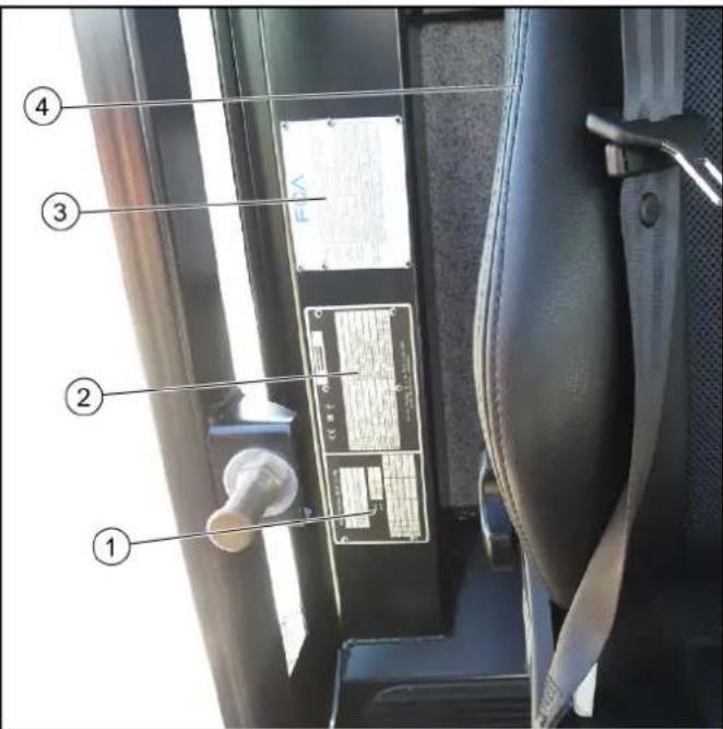
1 Frame factory nameplate
2 Vehicle factory nameplate
3 Engine factory nameplate
4 Driver's seat
4.9 Chassis number position (VIN)
Note
The chassis number is located on the right side of the frames in the direction of travel, in the area of the front wheel.
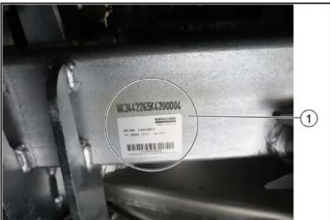
1 Chassis number
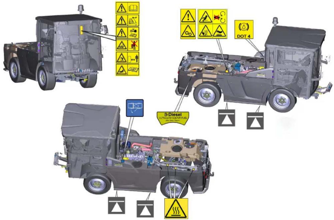
4.10 Symbols on the vehicle
Note
Immediately replace illegible or absent symbols.
| △DANGER Risk of burns from hot surfaces Allow the vehicle to cool down before working on it. | |
| △DANGER Risk of burns due to hot exhaust pipe Do not touch the exhaust pipe. Before working, allow the exhaust pipe to cool down. | |
| Max 10° | △DANGER Danger of tilting Only drive on terrain with a maximum lateral in-line of 10°. |
| △DANGER Risk of injury on account of splashing objects Keep an adequate distance from persons, animals and objects. | |
| △WARNING Risk of injury Risk of being squeezed or hurt at the belts, side-brushes, waste container, cover. | |
| △DANGER Risk of crushing When using the vehicle as a tractor, make sure that there are no persons between the vehicle and the trailer during operation. | |
| ATTENTION Rotating machine parts. | |
| △DANGER Risk of injury from rotating parts Open the bonnet only when the motor has come to a halt. | |
| △WARNING Health risk due to poisonous exhaust gases Do not inhale exhaust gases. | |
| △DANGER Risk of injury due to unauthorised usage Remove the ignition key to protect against unauthorised use and prior to cleaning and maintenance work. |
| ATTENTION Safety for cleaning and maintenance Prior to cleaning and maintenance work, park the vehicle on a level and firm subsurface. | |
| △DANGER Danger of injury due to use of unspecified locations for seating Sit exclusively on the driver's seat. | |
| △DANGER Risk of injury due to rolling over No persons may be present in the vicinity of the vehicle during use. | |
| △DANGER Risk of impact, risk of crushing When transporting or working under suspended loads, use suitable means for supporting. | |
| Lubrication point | |
| Use DOT 4 brake fluid | |
| Refuel with diesel according to DIN EN 590 | |
| Attachment point for jack | |
| Open the engine cowling | |
| Read operating instructions |
4.11 Position of the symbols on the vehicle
Note
Immediately replace illegible or absent symbols.
4.12 Safety devices
Safety devices protect the user and may not taken out of operation or functionally circumvented.
Adhere to the safety instructions in the chapters!
4.12.1Start inhibitor
Requirements for starting the engine:
-
Driver is sitting on the driver's seat
Neutral position of the travel direction selector switch -
If the travel direction selector switch is in the forward or reverse direction when starting the engine, the engine can still be started, but driving is only possible if the direction switch is first brought to the neutral position.
- Operate the battery disconnector relay switch. See "Battery disconnector relay switch" chapter.
① Battery disconnected (vehicle starting disabled)
② Battery activated (vehicle can be started)
4.12.2Seat contact switch
When the driver's seat is vacant:
The vehicle cannot be driven.
- The front PTO cannot be switched on or off.
4.12.3 Parking brake
The parking brake requires hydraulic pressure to release. The brakes are automatically actuated when the engine is switched off.
The parking brake is also applied when the engine is running and the travel direction lever is in the NEUTRAL position.
Note
The "Parking brake applied" warning light in the multifunction display lights up when the parking brake is applied.
4.12.4Driver cabin
The operator is protected from lightning strikes when sitting in the driver cabin.
The driver cabin has a roll-over protection structure
(ROPS), which prevents rolling over after tipping over.
The driver cabin does not have a structure providing protection from falling objects (FOPS).
The driver cabin does not have a structure providing protection from falling objects (OPS).
Always use the safety belt.
5 Batteries / chargers
ATTENTION
Only use the batteries and chargers recommended by the manufacturer
Only replace batteries with batteries of the same type. Before disposing of the vehicle, remove the battery and dispose of it in accordance with national or local regulations.
5.0.1 Warning symbols
Observe the following warnings when handling the batteries:
| Observe notes in the instructions for the battery, on the battery and in these operating instruc-tions. | |
| Wear eye protection. | |
| Keep acids and batteries away from children. | |
| Risk of explosion | |
| Fire, sparks, open flames and smoking are pro-hibited. | |
| Risk of acid burns | |
| First aid. | |
| Warning | |
| Disposal | |
| Do not throw batteries in the bin. |
5.0.2 Safety instructions
DANGER
Risk of fire and explosion
Do not place tools or other objects on the battery.
Naked flames and smoking must be strictly avoided.
Ensure the room is well ventilated when charging batteries.
Only use batteries and chargers approved by Karcher (original spare parts).
WARNING
Environmental risk due to improper disposal of batteries
Ensure that defect or used batteries are disposed of safely (contact a waste management company or Kärcher Service).
Procedures in the event of unintentional release of battery acid
When used normally, and when observing the instructions, lead-acid batteries do not pose any risk. However, keep in mind that lead-acid batteries contain sulphuric acid which can cause serious chemical burns and corrosion.
- If there is spillage or, if the battery is leaking, acid is escaping, lay down a binding agent such as sand. Do not let it reach the sewer system, soil or a body of water.
- Neutralise the acid with lime/baking soda and dispose of it according to local regulations.
- Contact a waste management company to dispose of faulty batteries.
- Rinse out your eyes or rinse off your skin with copious amounts of fresh water if acid splashes into your eyes or onto your skin.
- Then consult a doctor immediately.
- Wash any contaminated clothing with water.
- Change clothes.
6 Vehicle overview
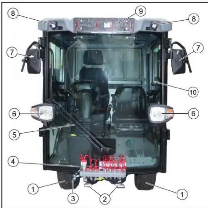
6.1 Front view
①Front wheel
② Attachment mount
③ Attachment power supply
4Hydraulic connections
⑤Windscreen wiper
⑥ Driving light/flasher
⑦ Rear view mirror, heated (option)
⑥ Working light
Licence plate bracket
Driver cabin with lockable doors
Towing device
The front towing device is attached to the left frame and secured by a retaining pin.
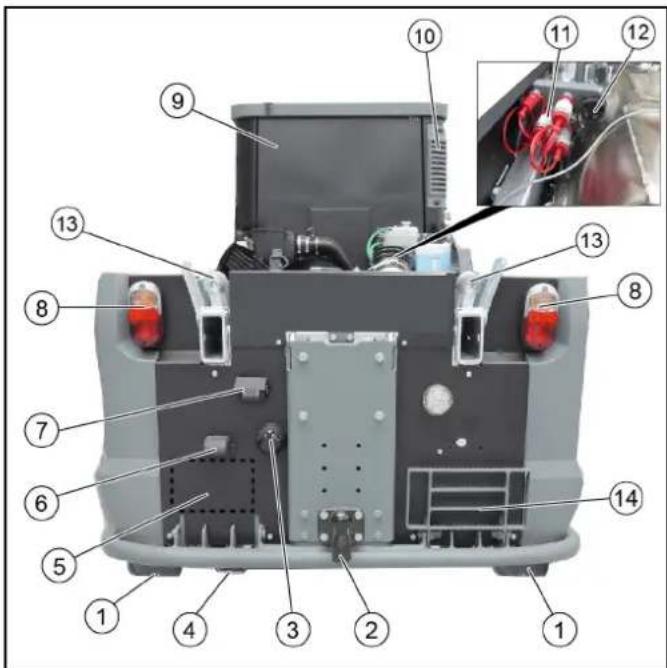
6.2 Rear view
Rear wheel
② Trailer coupling
③ Socket for trailer / attachments
Exhaust pipe
⑤ Licence plate mounting area
⑥ Licence plate lights
⑦ Reversing camera
Tail light / brake light / turn signal
Driver cabin
10 Driver cabin dust filter
Hydraulic connections
12Attachment power supply
13Mount for waste container attachment
Step, foldable
6.3 Hydraulic connections
Definition of the term, hydraulic PTO
Power Take Off = hydraulic force output
Definition of the term, AUX
Auxiliary valve
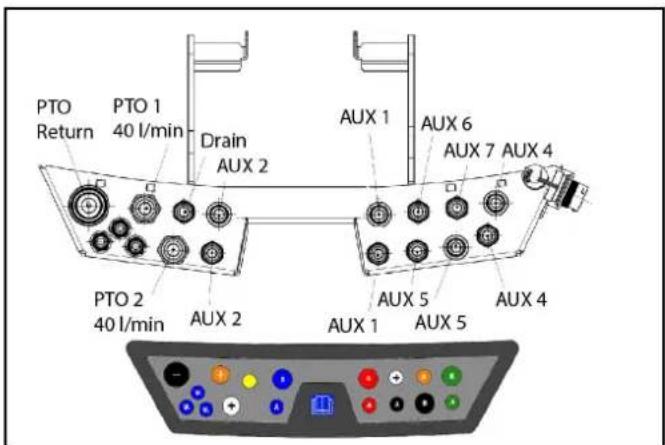
6.3.1 Front hydraulic connections
Note
Fit a dust cap to an unused connection to provide protection.
6.3.2 Rear hydraulic connections
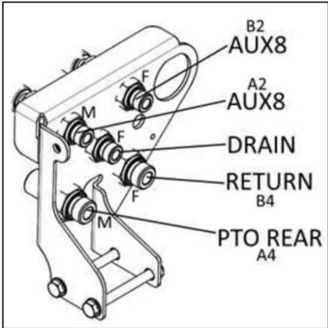
Note
Fit a dust cap to an unused connection to provide protection.
6.4 Panels
For various maintenance or cleaning work, the corresponding panels must be opened. The description of the maintenance and cleaning work can be found in the "Care and maintenance" chapter.
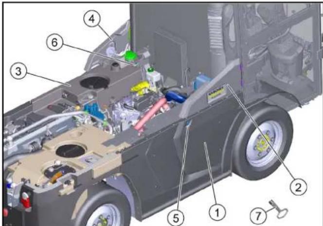
Figure: Shown without cover
① Radiator grille, hinged
② Right-hand service flap, hinged.
③ Bonnet/fresh water tank, hinged
4Left-hand service flap, hinged.
⑤ Radiator grille lock
6 Bonnet/water tank lock
⑦ Square wrench (included in scope of delivery)
- Radiator grille: Unlock with square wrench and swing outwards.
a Cleaning the combination cooler
b Cleaning the air-conditioner condenser
- Right-hand service flap: Swing out to open.
a Refilling with DEF or AdBlue®
b Checking / filling the wiping water
c Checking / topping up the expansion tank coolant
- Bonnet/fresh water tank: Unlock with a square wrench and swing outwards.
a Checking the engine oil level
b Emergency release of the parking brake
c Check the brake fluid filling level
- Left-hand service flap: Swing out to open.
a Cleaning the air intake on the side of the air filter housing
b Opening the air filter cover from above and cleaning the air filter
- Square wrench: For unlocking the radiator grille and bonnet/water tank
7 Driver cabin
7.1 Doors
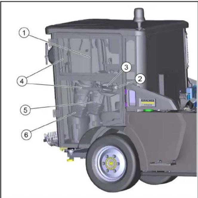
① Sliding window (2-piece)
②Door lock
③ Door handle
4 Handle
Right-hand steering variant
Left-hand steering variant
Close both doors after parking the vehicle.
The driver's doors each serve as an emergency exit.
Right-hand steering variant
The driver's seat and the driver's door are located to the right in the direction of travel, a second door is located on the left side of the driver cabin.
Left-hand steering variant
The driver's seat and the driver's door are located to the left in the direction of travel, a second door is located on the right side of the driver cabin.
Entry and exit aid
Handles that can be used as entry and exit aids are located inside the doors and on the A-pillar.
7.2 Interior filter
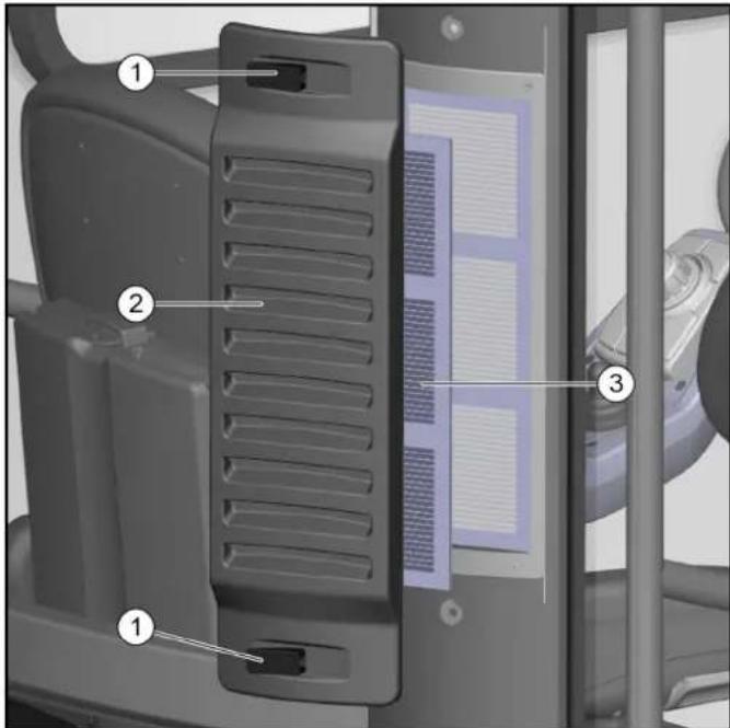
①Lock
Bar cover
③ Fine dust filter, filter class F9
The fresh air is drawn in through a fine dust filter at the driver cabin (rear right).
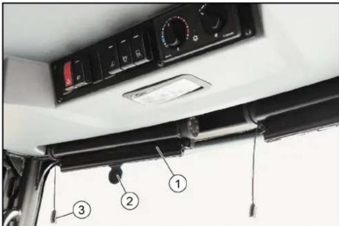
7.3 Radio
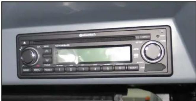
The optionally available radio is locate in the ceiling console.
See the manufacturer's operating instructions for operating the radio.
7.4 Switch panel
The switch panel is located in the ceiling console.
Note
The indicator in the switch lights up when it is switched on.

① Warning flasher system switch
Upper position: Off
Lower position: On
② Lighting switch
Upper position: Driving light off
Central position: Parking light on
Lower position: Driving light on
③ Rear fog light (option)
Upper position: Off
Lower position: On
④ Front working light switch
Upper position: On Lower position: On
⑤ Flashing beacon switch
Upper position: Off
Lower position: On
Switch for heatable outside mirror (option)
Upper position: Off
Lower position: On
⑦ Switch for windscreen heating (option)
Upper position: Off
Lower position: On
Heating / air-conditioner
Operation is described in a special chapter.
7.5 Heating, ventilation, air-conditioner
The control elements are located in the ceiling console.

① Temperature controller for cooling / heating
②Air-conditioner on / off
Note
The air-conditioner will not be activated until the blower motor speed controller is at least at level 1.
Switch above: Air-conditioner on - indicator lights up
Switch below: Air-conditioner off
③ Controller for blower motor
- Make sure you have a comfortable climate while in the driver cabin. Adjust this using the control elements.
① Ventilation nozzles
- Adjust the ventilation nozzles draft-free. Press the ventilation flap to open / close. Turn the ventilation flap to change the direction of the airflow.
Footwell air duct
3. Keep the air duct free in the footwell in front of the windscreen. Otherwise it will fog up.
7.5.1 Automatic air-conditioner (optional)
The control elements are located in the ceiling console.
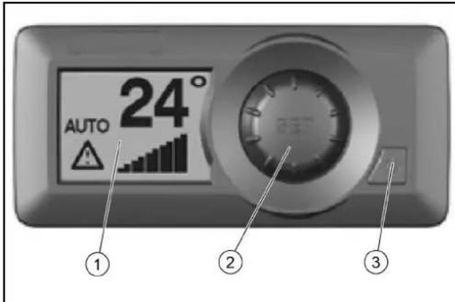
① LCD display
②Adjustment button (SET)
③ Air-conditioner on/off
-
After switching on, the LCD display shows the selected temperature, the fan speed and the selected setting. a In the test/diagnostic mode, it displays appropriate messages for troubleshooting.
-
The settings can be selected using the adjustment button. To do this, switch on the air-conditioner.
a Press the adjustment button (SET).
b Turn the adjustment button clockwise or counterclockwise to select the desired settings.
c The system automatically returns to the main display after a few seconds with the selected settings. Do not press the adjustment button.
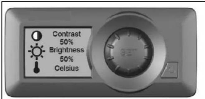
3. To set the contrast and brightness of the display, as well as the temperature display in ^ C or ^ F , press the adjustment button twice with the air-conditioner switched on.
Make the required settings by turning it clockwise or counterclockwise. Press the adjustment button once to save. Wait a few seconds, the system will automatically return to the main display.
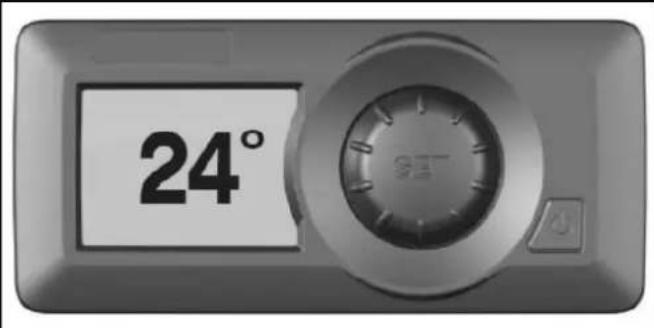
4. When the air-conditioner is turned off, the backlight turns off and the preset setting is displayed.
5. The air-conditioner also has menus for setup, fault displays or statistics. This is reserved for the authorized Customer Service. If you have any questions or in the event of a fault, please contact the authorized Customer Service.
7.6 Interior lighting

① Press left: Lighting on
② Middle position: Lighting is switched on by opening a door
3Press right: Lighting off
7.7 Sun visor
Sun visor
② To operate, pull down to the desired position
③ Pull to unlock, sun visor moves upwards
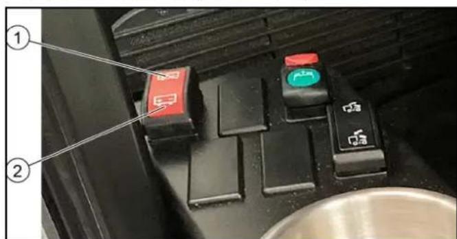
7.8 Console at the driver's seat
A console with switches, a storage container for various small parts and sockets for USB and 12V is located next to the driver's seat.
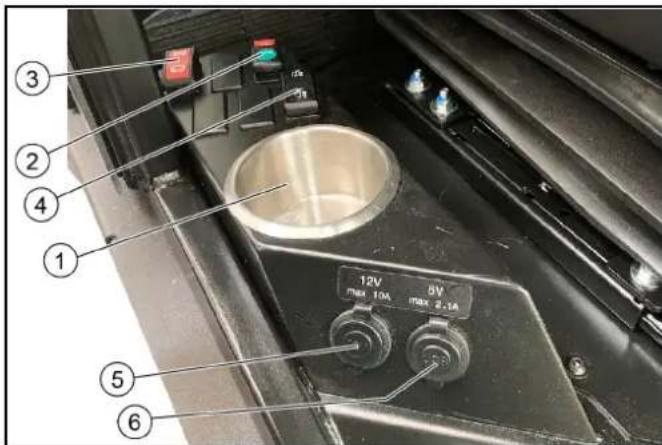
Storage container
Drain recycling water switch (optional with sweeping attachment kit)
③ Battery disconnector relay switch
Waste container emptying switch (optional with sweeping attachment kit)
⑤ Additional socket 12V / max. 10 A
USB connection 5V / max. 2.1A
7.8.1 Battery disconnector relay switch
All functions used for the vehicle can be deactivated with the battery disconnector relay switch.
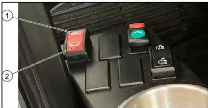
Switch setting "Disconnect battery"
②Switch setting "Activate battery"
- Disconnect the battery each time the vehicle is parked by pressing the switch to the "Disconnect battery" position. Please wait at least 60 seconds after switching off the combustion engine before operating the switch.
Note: After the combustion engine has been switched off, the control units are gradually deactivated. The battery can only be disconnected after the last device has shut down. Therefore, observe the waiting time of 60 seconds.
- To start up, activate the battery by pressing the switch in the "Activate battery" position.
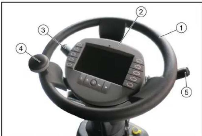
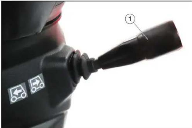
7.9 Steering wheel panel
① Steering wheel
②Display with function buttons
③ Multi-function switch
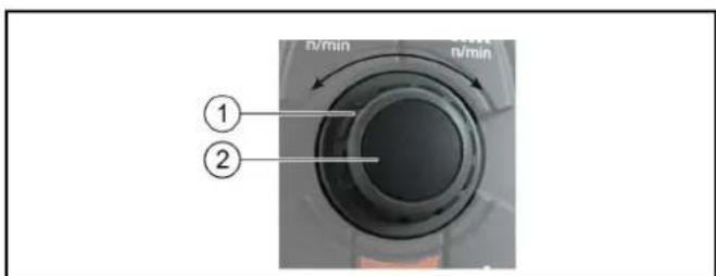
④ Steering wheel knob
⑤Travel direction selector switch
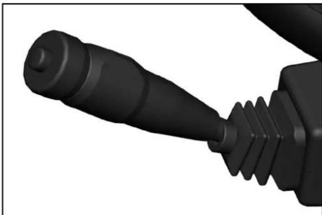
7.9.1 Multi-function switch
- Horns: Press the button on the end
- Flash to the right: Lever forwards
- Flash to the left: Lever backwards
High beam: Press the lever down with the driving light switched on - Flasher: Pull lever and release
- Windscreen wiper interval: Turn the ring forward
Note
The period of the wiper interval is adjustable (programmable).
To do this, turn the ring to "Intermittent wiping", wait for the desired time interval then switch it off and switch it on again within 1.5 seconds. The set time interval returns to its basic programming after switching off the ignition.
- Continuous wiping: Turn the ring backwards
Note
1st level for normal wiping speed
2nd level by turning further for fast wiping speed
Wiping water: Press the ring
7.9.2 Travel direction selector switch
The travel direction is selected using the travel direction selector switch.
ATTENTION
The vehicle must be at a standstill and the travel direction selector switch in the neutral position in order to select the travel direction.
Operating error
If the direction switch is in the forward or reverse direction when selecting the travel direction, the symbol display will change but the switchover will not occur.
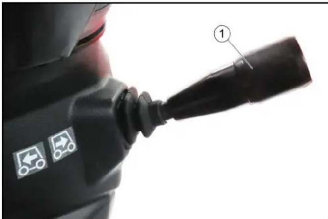
①Travel direction selector switch
- Pull the selector switch upwards towards the steering wheel, then move it in the desired direction of travel (front / rear).
The travel direction is shown in the display. - Bring the travel direction selector switch into the middle position (neutral position).
The driving engine idles. - Select the desired transport speed or working speed using the accelerator pedal.
7.9.3 Ignition lock
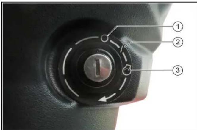
Engine off
② Ignition on
③ Start the engine
The ignition lock is located below the travel direction selector switch.
7.10 Pedals
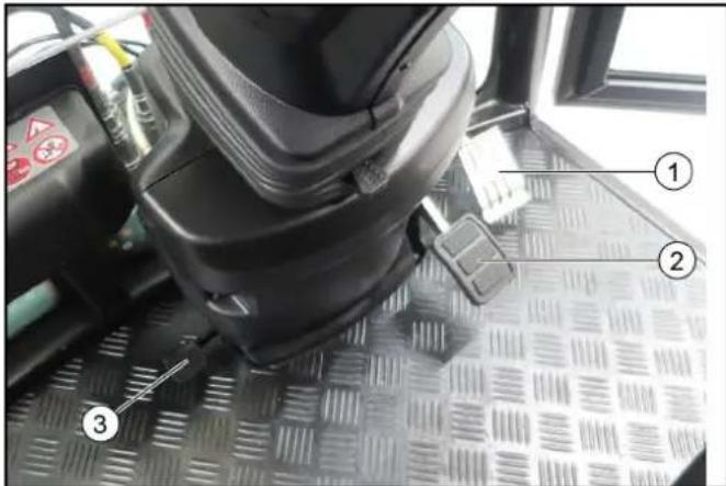
① Accelerator pedal
② Brake pedal
③ Pedal (no function, only active with "Sweeping attachment kit")
7.10.1Accelerator pedal
Note
Releasing the accelerator pedal provides no noticeable braking effect in transport mode.
The brake pedal must be pressed in order to brake.
1 Transport mode: Pressing the accelerator pedal increases the engine speed and the driving speed.
Releasing the accelerator pedal reduces the engine speed and the driving speed.
2 Working mode: The engine speed is set to a fixed value. Regulate the desired working speed using the accelerator pedal.
Only the working speed and not the engine speed decreases when the accelerator pedal is released.
7.10.2 Brake pedal
The brake pedal activates the front and rear wheel braking system.
The brake pedal must be pressed in order to brake.
Note
Releasing the accelerator pedal provides no noticeable braking effect.
7.10.3 Parking brake
The parking brake requires hydraulic pressure to release. The brakes are automatically actuated when the engine is switched off.
The parking brake is also applied when the engine is running and the travel direction lever is in the NEUTRAL position.
Note
The "Parking brake applied" warning light in the multifunction display lights up when the parking brake is applied.
7.11 Display
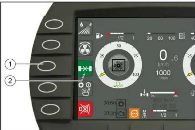
7.11.1Function buttons/setting buttons
The following indicators are shown on the display after switching on the ignition.
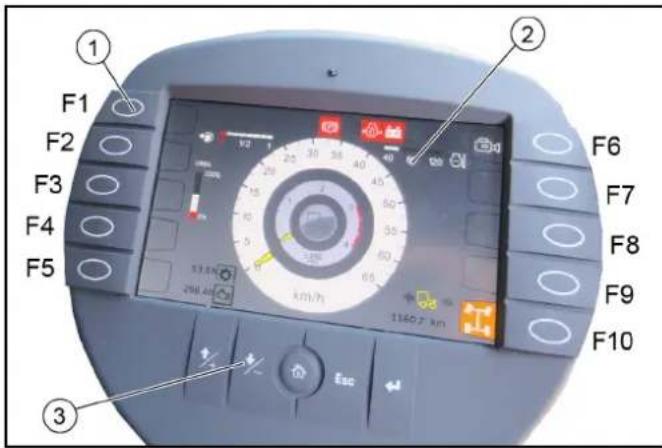
Function buttons
②Display indicator in start/transport mode
③ Setting buttons
Pressing the corresponding function button changes the display. Return by pressing again or by pressing the "Home" button.
The settings are changed using the settings buttons.
| Assignment of the function buttons | |
| F1 Information such as the vehicle operating instruc-tions can be provided here In working mode: Switch on high-pressure cleaner (option) | |
| F2 Display the date and time | |
| F3 Various settings | |
| F4 In working mode: Bridging the seat contact switch | |
| F5 Reversing warning buzzer on/off | |
| F6 Reversing camera on/off | |
| F7 Suction-mouth camera (optional with sweeping at-tachment kit) | |
| F8 Set Tempomat | |
| F9 Resume Tempomat | |
| F10 Choice of 2 or 4-wheel steering | |
| Setting but- tons | ||
| + button Jumps | one field up when mak- ing settings | |
| - button Jumps | one field down when making settings | |
| "Home" button | Navigates to the "Home" screen for the respective operating mode (Transport / Work) |
| Setting but-tons | ||
| Esc button | Jumps one step back when making settings | |
| "Return" but-ton | Completes a setting procedure |
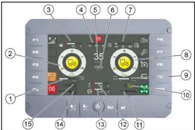
7.11.2Display indicators in start/transport mode
The following values are shown on the display in Start/ Transport mode.
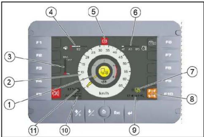
①Engine speed
②Travel speed
DEF reservoir filling level
④ Fuel level indicator
⑤ Parking brake warning light actuated
Engine coolant temperature
Driving direction indicator
- Forwards direction of travel
- Neutral position
Travel direction backwards
⑧2-wheel / 4-wheel steering indicator
Mileage
Engine operating hours
1 Working hours meter
7.11.3 Working mode displays
The following indicators are shown on the display when switching to Working mode (PTO).
①Engine load display
② Front attachment drive triggering level in % -Yellow pointer: PTO on the left
Grey pointer: PTO on the right
③ Fuel level indicator
4Hydraulic oil Temperature
⑤ Working speed
⑥ Engine speed
Engine coolant temperature
Rear attachment drive triggering level in %
⑨ DPF regeneration display
Driving direction indicator
⑩Mileage
12 Fresh water tank (only with optional sweeping attachment kit)
⑬ Recycling water tank (only with optional sweeping attachment kit)
14Operating hours counter
15Working hours meter
7.11.4Select steering (2-wheel / 4-wheel)
Transport mode and 2-wheel steering are automatically selected when starting the engine.
In working mode (PTO on), the 4-wheel steering can be selected.
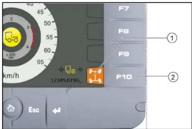
① Steering mode display (2-wheel / 4-wheel)
②Function key F10
1. Press function key F10.
2. Turn the steering wheel over the centre position (reference point). If the display turns green, the steering mode is activated.
7.11.5 Reversing camera
The reversing camera is located at the rear of the vehicle. When reversing, the camera automatically turns on and appears in the display.
WARNING
The reversing camera is no substitute for an awareness of the surroundings
Always pay attention to the surroundings when reversing. Ensure no persons, animals or objects are located in the manoeuvring range.
7.11.6Bridging the seat contact switch
Note
Is required when performing work where the driver must leave the driver's seat, e.g. with the manual suction hose (option) or high-pressure cleaner (option).
- Travel direction selector switch to the NEUTRAL position.
- Activate the hydraulic system (PTO on).
- Press function key F4 on the display.
The "Seat contact switch overridden" warning symbol appears on the display.
The seat contact switch is now bridged and the PTO remains active.
7.11.7Symbols on the display
- Green indicator lights are indications.
- Orange indicator lights are indications of errors or pending switchovers of operating states:
a It is possible to continue driving with appropriate caution.
b Seek the help of a specialist.
- Red indicator lights are errors and safety-related warnings.
a Read the operating instructions!
b Do not drive further!
c Seek the help of a specialist.
The following indicator lights can be shown on the display.
| ○○ | Parking light |
| ○D | Driving light |
| ○D | High beam |
| ←→ | Driving direction indicator |
| ←2→ | Trailer indicator light |
| Crossroads function active | |
| 1 | AUX X floating function active |
| 2 | AUX Y floating function active |
| 1+2 | AUX X and Y floating function active |
| 99 dB | Function 99 dB(A) active |
| Reversing camera active | |
| 2-wheel steering activated | |
| I | 2-wheel steering ready for selection |
| II | 4-wheel steering activated |
| III | 4-wheel steering ready for selection |
| IV | Differential lock activated |
| V | Differential lock under preparation |
| VI | Cruise control activated |
| VII | Cruise control inactive |
| VIII | Cruise control (Resume) Activate the previously set speed |
| IX | Neutral position (middle position) of the travel direction selector switch required |
| X | Steering error |
| XI | Seat contact switch not recognized |
| XII | Seat contact overwritten manually (bridged) |
| XIII | Service required |
| XIV | Preheating active |
| XV | General fault (uncritical), check fault list |
| XVI | Fuel level warning |
| XVII | Perform the regeneration process |
| Engine malfunction (uncritical) | |
| Warning, engine must be switched off | |
| Warning, working hydraulics must be switched off | |
| Working hydraulics must be switched on | |
| Axle load warning | |
| Drive oil temperature warning | |
| High hydraulic oil level warning | |
| Reverse function active | |
| Fog lights on | |
| High exhaust temperature (regeneration is active) | |
| Regeneration is active (Inhibit) | |
| Vehicle power is limited, speed is limited | |
| Warning, vehicle is in limited condition (transport mode) | |
| Warning, generator system is faulty | |
| Warning, axle load too high | |
| Drive oil temperature fault | |
| DCU fault (control unit) | |
| DCU in stop state | |
| Warning, reversing not allowed | |
| Low hydraulic oil level warning | |
| Hydraulic oil filter malfunction | |
| Warning, hydraulic oil temperature high | |
| Seat contact switch malfunction | |
| Engine air filter malfunction | |
| Critical malfunction, switch off the engine | |
| Warning, engine coolant temperature too high | |
| Parking brake active | |
| Reversing signal off | |
| Warning, brake pressure too low | |
| Warning, engine oil pressure too low | |
| Switch off the engine | |
| Engine fault warning • If the engine fault is active, the warning lamp lights up permanently | |
| Water from the engine in the fuel | |
| Engine fault in the exhaust treatment system | |
| Warning, hydraulic circuits are automatically vented (only when starting up for the first time) | |
| Warning, hydraulic controller offline | |
| Warning, display offline | |
| Warning, safely activate 2-wheel steering | |
| Warning, speed is too high - reduce speed | |
| Warning, service brake faulty | |
| Warning, parking brake faulty | |
| Brake fluid warning | |
| Warning, engine temperature high |
4 Operating consoles
4.1 Arm rest control panel
The control panel is located on the arm rest next to the driver's seat. The arm rest can be individually adjusted to suit the driver, see chapter "Setting the driver's seat".
4.1.1 Device carrier control assignments
Note
The indicators in the switches light when the switches are switched on.
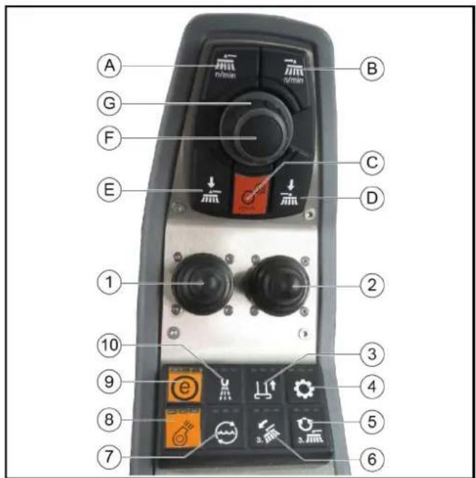
① Left joystick
RightJoystick
Not used
④Switching the hydraulic system on/off
Not used
6Not used
Electrical AUX 1 rear / AUX 3 front
Switching the rear PTO on/off
Not used
10 Electrical AUX 2 rear / AUX 4 front
(A) Front PTO, 40 l/min maximum
The hydraulic power can be adjusted via a potentiometer
(B) Front PTO, 40 l/min maximum
The hydraulic power can be adjusted via a potentiometer
(C) Button for setting the engine speed
Note
The speed can be adjusted in steps of 100 rpm.
(D) Not used
(E) Rear PTO, 60 l/min maximum
(F) Press the button to save set values or programs and open submenus.
(G) Rotary knob for changing values and selecting programs.
5 Di s p I a y
Note
The default display language is English, but the language can be changed via the Settings menu.
The display can be used for e.g. making vehicle settings, making settings for the display and displaying vehicle information.
In detail, these are the following functions described below.
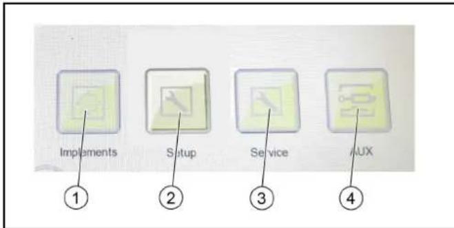
Selection and configuration of the attachments
② Settings
-Display settings
- System information
- DPF (information on regeneration)
③Service
- This area is reserved for customer service
AUX
Pressure relief of the hydraulic system
① Rotary knob for changing values and selecting programs
② Press the button to save set values or programs and to open submenus.
1 The central elements for navigating and selecting the menu items in the display are the rotary knob and button.
2 Pressing the button opens submenus and saves selected settings.
3 The menu items can be selected using the rotary knob.
| Back button Select the button and press the pushbutton to return to the main menu | |
| Home button back Select the button and press the pushbutton to return to the main menu | |
| OK button Select the button and press the pushbutton to save the settings |
5.1 Attachments menu
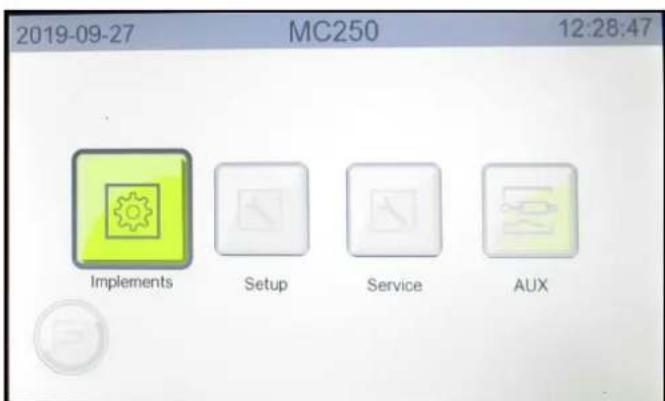
Figure: Attachments menu selection
If attachments are attached to the vehicle, they must be configured in the menu. The following configurations, among others, can be selected:
Device carrier
Sweeper
Winter service
Wet cleaning
5.2 Settings menu
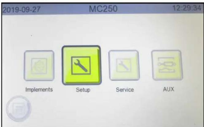
Figure: Settings menu selection
The Settings menu contains the following submenus.
Service
- This menu item is reserved for authorise customer service personnel
- Settings
- Display brightness and contrast
- Speed units (km/h / mph) and temperature units (^/ F
Language - Date and time
-Infos
- Display of vehicle-specific system information
- DPF (Diesel particle filter)
- Indicator shown when the next automatic regeneration will start
5.2.1 Making display settings
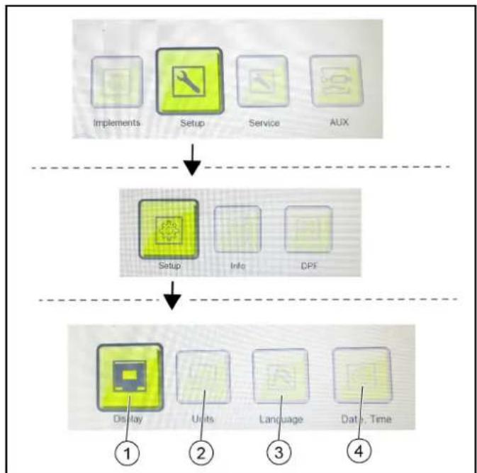
①Display brightness and contrast
②Speed and temperature units
③Language
Date, time
- Press the "Settings" button until reaching the display settings level.
- Use the "Display", "Units", "Language" and "Date, Time" buttons to open the submenus and make the desired settings.
5.2.2 Display system information
- Use the "Settings" and "Infos" buttons to access the system information window.
5.2.3 DPF (Diesel particle filter)
- Use the "Settings" and "DPF" buttons to access the DPF window.
See chapter for further information 7.4 Regeneration process for vehicles with a diesel particle filter (DPF).
5.3 Service menu
Figure: Service menu selection
This menu is reserved for the authorized Customer Service.
5.4 AUX menu (depressurize the hydraulic system)
The hydraulic system must be depressurised before disconnecting the hydraulic hoses from the hydraulic connections.
CAUTION
Risk of injury, risk of damage
Lower lifted attachments before depressurizing.
① Front AUX pressure relief
Rear AUX pressure relief
- Select the menu items with the button and rotary ring on the control panel. Confirm the selected setting with the button.
a Switch to the next level by pressing the "AUX" button.
b Select AUX pressure relief front or rear.
6 Initial startup
CAUTION
Read the operating instructions for attachments!
When using attachments or pulled devices and trailers prior to initial startup, read the corresponding operating instructions and follow them.
Pay attention to permissible loads, see chapter.
6.1 Safety checks before startup
△DANGER
Risk of accident and injury due to faulty vehicle
Do not start up the vehicle if one point from the safety check is not fulfilled but rather repair the vehicle.
Note
Perform the recommended safety checks each time before using the vehicle.
6.1.1 Device carrier safety check
Check the following points before each startup:
- If the battery disconnector relay switch is set to "Battery activated". See chapter 7.8.1 Battery disconnector relay switch
- Check the cleanliness of the hydraulic connections
- Check the hydraulic lines for leakage and damage
- Check the hydraulic oil level, see chapter 10.7.3 Checking the hydraulic oil level and topping up the hydraulic oil
- Check the engine oil level, see chapter 10.7.8 Checking/topping up the engine oil level
- Check the coolant level, see chapter 10.7.2 Checking the coolant level and topping up the coolant
- Check the brake fluid level, see chapter 10.7.10 Checking the brake fluid level in the reservoir
- Check the coolant for sufficient antifreeze if a danger of frost exists
- Check the electrical cables for damage
- Check that all nuts and bolts are securely seated
- Check the vehicle, engine and radiator grille for damage
- Check the cleanliness of the engine air filter
- Check the cleanliness of the cab dust filter
- Check the fluid level in the windscreen washer reservoir, see chapter 10.7.1 Filling the wiping water container
15.Type pressures and tyre wear - Check that the lighting and flashing system function
17.Ease of movement of the accelerator pedal
18.Are the temperature indicator and fuel level indicator functioning?
6.2 Setting the driver's seat
△DANGER
Danger of accident
Only adjust the driver's seat when the vehicle is stationary.
CAUTION
Risk of damage
Do not use the folded backrest as a storage area when driving on public roads or secure accordingly
ATTENTION
Only the seats listed below and offered by Kärcher may be used. Otherwise the vibration values cannot be guaranteed.
Note
The driver's seat is automatically damped.
Note
If there is no passenger seat, there is a directly accessible storage compartment
Kärcher offers 3 variants of driver's seats:
① Horizontal adjustment Pull the lever upwards to adjust
② Driver's seat with air suspension
③ Backrest inclination adjustment
Lumbar support adjustment
⑤Seat belt
6Seat heater switch
Headrest Pull out or push in for height adjustment
Arm rest with control panel
⑨ Passenger seat (option)
- Seat Cobo SC47M-M200 (shown without arm rest)
Driver's seat
② Horizontal adjustment Pull the lever upwards to adjust
③ Damping setting for driver weight
4Seat belt
(5)Lever, fold backrest
Headrest Pull out or push in for height adjustment
- Seat Grammer MSG75GL / 522 (shown without arm rest)
① Driver's seat with air suspension
② Height adjustment
③ Horizontal adjustment Pull the lever upwards to adjust
4Seat belt
⑤ Backrest inclination adjustment
- Adjust the inclination, height and position of the left arm rest for operating the control panel.
- Adjust the driver's seat so that the pedals and steering wheel can be operated safely. The Grammer and König driver's seats have a lumbar support (lumbar support).
- The height of the air-sprung driver's seat (Grammer and King) can still be adjusted, bring the seat into the highest possible position using the compressor, then release air with the spring until the seat has dropped 2-3 cm.
- The passenger seat backrest and seat are hinged. Under the seat there is a storage compartment that can be used for storing vehicle documents and miscellaneous small items.
6.3 Setting the steering wheel position
△DANGER
Danger of accident
Only adjust the position of the steering wheel when the device is standing.
① Steering wheel height adjustment locking lever
② Steering wheel inclination adjustment lever
- Pull and hold the inclination adjustment lever and set the steering wheel to the desired inclination.
- Push in the lever.
- Release the height adjustment locking lever and set the steering wheel to the desired height.
- Lock the locking lever.
6.4 Refuelling
① Fuel cap
② Right side panel
DEF container closure
6.4.1 Refuelling
△DANGER
Risk of explosion
Do not refuel in confined spaces.
Do not smoke and avoid open flames.
Ensure that no fuel gets on hot surfaces.
CAUTION
Risk of injury
Note the risk of slipping due to spilt fuel.
ATTENTION
Fuel expands when heated, do not fill up to the brim.
- Switch off the ignition.
- Open the tank cap.
- Fill with fuel.
Only diesel fuel according to DIN EN 590 may be used.
- Wipe of any spilt fuel and close the tank cap.
6.4.2 Fill DEF or AdBlue®
DEF (Diesel Exhaust Fluid) is manufactured in compliance with strict quality standards. Only use a fluid that complies with ISO 22241 standards.
ATTENTION
It is prohibited to use urea solutions whose properties differ from those specified.
ATTENTION
Where possible, do not partially fill the tank with partial quantities otherwise a warning light is displayed. If this warning light comes on you cannot reset it, but it goes out after several refuelling operations. This does not affect the functionality.
Only refuel when the filling level of the DEF container is well below 50% (shown in the display).
- Open the right-hand service flap.
- Open the blue DEF reservoir cap.
- Add DEF, do not overfill.
Rinse off excess DEF with plenty of water.
- Close the reservoir cap and right-hand service flap.
7 Operation
△DANGER
Risk of crushing
Make sure that there no persons are in the vicinity of the vehicle during operation.
When using the vehicle as a tractor, make sure that there are no persons between the vehicle and the trailer during operation.
CAUTION
Risk of burns
Only use the vehicle if all panels are attached.
ATTENTION
Risk of damage due to overheated hydraulic oil or overheated engine
If the hydraulic oil temperature is too high or the coolant temperature is too high, run the engine at idling speed until the temperature drops below the "warning lamp off" trigger value.
ATTENTION
Risk of damage due to lack of lubrication
If the "Engine oil pressure" warning light comes on during operation, immediately move the vehicle out of the hazard zone of the flowing traffic and switch off the engine. Then have the fault fixed.
CAUTION
Reduced stability due to attachments
Adjust the driving style.
7.1 During the first 10/50/100 operating hours (running-in period)
- Drive the first 100 hours of operation gently and avoid overloading.
- After 50 operating hours: Initial inspection must be carried out by the authorized Customer Service according to the inspection checklist (ICL).
After 10 operating hours: Check the wheel bolts.
7.2 Parking brake
The parking brake requires hydraulic pressure to release. The brakes are automatically actuated when the engine is switched off.
The parking brake is also applied when the engine is running and the travel direction lever is in the NEUTRAL position.
Note
The "Parking brake applied" warning light in the multifunction display lights up when the parking brake is applied.
7.3 Drive mode
7.3.1 Start the engine
- Sit in the driver's seat.
- Insert the ignition key in the ignition lock.
- Bring the travel direction selector switch into the middle position (neutral position).
- Switch on the ignition.
- Wait until the display is complete.
- Start the motor.
If the charge indicator and engine oil pressure warning lights do not go out, switch off the engine and remedy the fault. See chapter "Error messages in symbol displays"
- In the event of ambient temperatures below 0^ : Warm up the vehicle at low engine speed.
7.3.2 Selecting the travel direction
For a more detailed description of the travel direction selector switch, see the chapter "Steering wheel console | Travel direction selector switch"
①Travel direction selector switch
- Pull the selector switch upwards towards the steering wheel, then move it in the desired direction of travel (front / rear).
The travel direction is shown in the display.
- Select the desired transport speed or working speed using the accelerator pedal.
7.3.3 Driving
WARNING
Danger of accident
Only drive with the attachment properly mounted.
CAUTION
Risk of damage
Make sure that the vehicle does not become stuck when driving over obstacles.
Drive over obstacles up to 150mm slowly and carefully at an angle of 45^ .
Obstacles above 150mm may only be driven over using a suitable ramp.
CAUTION
Risk of damage due to flashing beacon
Pay attention to the protruding flashing beacon (2.20m) when driving into underground garages etc. If necessary, remove it beforehand. Do not stand on the bonnet (fresh water tank).
CAUTION
Danger of accident
Switch off the PTO when driving on public roads for transportation purposes (not when cleaning public roads).
Note
Releasing the accelerator pedal provides no noticeable braking effect.
- Fasten the seat belt.
- Carefully press the accelerator pedal.
- Steer the travel direction using the steering wheel.
- The brake pedal must be pressed in order to brake.
7.3.4 Stopping
- Take your foot from the accelerator pedal.
Note
Releasing the accelerator pedal provides no noticeable braking effect in transport mode.
2. To stop or in an emergency, press the brake pedal.
7.3.5 Differential lock (special option)
If the vehicle cannot move because the drive wheels are positioned on ground with different degrees of traction (e.g. asphalt / snow), the differential lock can be activated in order to drive the vehicle free.
ATTENTION
Activate the differential lock only when the vehicle is at a standstill!
Activating the differential lock
- Activate the Working mode, see chapter 7.11.3 Working mode displays.
- Activate the 2-wheel steering, see chapter 7.11.4 Select steering (2-wheel / 4-wheel).
If the indicator light "Warning, 2-steering not active - Turn the steering straight-ahead" lights up: Turn the steering to the straight-ahead position.
Function button F3
② Differential lock display
3. Press and hold function button F3.
The differential lock engages, the differential lock display lights up green.
If the rear axle is in a non-optimal position, it is possible that the differential lock does not engage immediately and the differential lock display lights up orange.
Press the accelerator pedal carefully until the differential lock engages.
- Drive the vehicle onto ground providing more traction while continuing to hold function button F3 pressed.
Deactivating the differential lock
- Release function button F3.
The differential lock disengages, the differential lock display lights up white.
Note
If the drive train is under tension, it is possible that the differential lock does not disengage immediately and the differential lock display lights up orange.
Driving with steering movements or with load variations will disengage the differential lock.
7.3.6 Tempomat
The Tempomat is only active in Working mode.
Activating Tempomat
1 Select the desired working speed using the accelerator.
2 Press function key F 8.
Tempomat is activated.
Deactivating Tempomat
1 Press the brake pedal or function key F 8.
Function key F 9 (Resume Tempomat) activates the previously set speed.
7.3.7 Parking the vehicle
△WARNING
Risk of injury due to attachments
Fully lower any mounted attachments.
- Stop the vehicle.
- Bring the travel direction selector switch into the neutral position (middle position).
The parking brake is automatically actuated in this position.
- Lower mounted attachments (not the sweeping system).
- Allow the engine to run in idle mode for 1 to 2 minutes.
- Switch off the ignition and remove the ignition key.
- For a longer stop, press the battery disconnector relay button. See "Battery disconnector relay" chapter.
- If the battery is to be disconnected, wait another 30 seconds for the engine control unit storage procedure to finish.
7.4 Regeneration process for vehicles with a diesel particle filter (DPF)
The DPF collects soot particles that are burned off by increasing the emission temperature when the filter is clogged (regeneration).
The regeneration process runs either automatically during working mode or driving mode but can also be started manually if required.
The higher the speed when driving, or the greater the load, the less frequent the need for manual regeneration.
7.4.1 Manual regeneration
WARNING
Risk of burns
During the regeneration process, exhaust gases up to a temperature of 600^ may be omitted.
Do not start the regeneration process in combustible areas.
CAUTION
Risk of burns from hot exhaust gases
Keep people, animals and flammable objects away from the regeneration area.
Note
Only interrupt the regeneration process in the case of an emergency.
Manual regeneration is not possible at less than 50 hours.
The average duration of the burning procedure during manual regeneration is approximately 20 minutes.
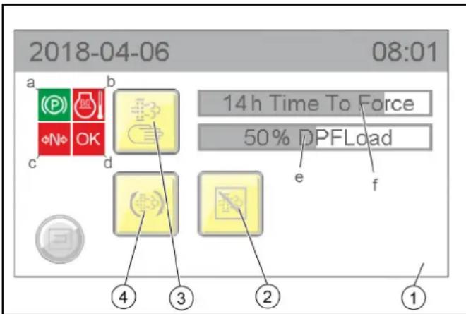
① Manual regeneration display
a) Parking brake display.
b) Engine temperature display
c) Driving mode display
d) OK display
e) Particle filter % fill degree display
f) Display of the hours remaining until manual cleaning can be started
②Postponing automatic cleaning
③ Activating manual cleaning
④Activating automatic cleaning
- Manual regeneration can only be started when all 4 characteristics are green:
a The parking brake is activated
b The engine temperature has exceeded a particular limit value
c The machine is in driving mode N (neutral)
d OK then lights up green and the manual burning procedure can be started
7.4.2 Automatic regeneration
WARNING
Risk of burns
During the regeneration process, exhaust gases up to a temperature of 600^ may be omitted.
Do not start the regeneration process in combustible areas.
Note
Work can continue during Automatic regeneration.
The automatic regeneration can be postponed in certain situations.
7.5 Winter use
7.5.1 Frost protection
- Check the frost protection of your vehicle. See chapter "Maintenance work | Check coolant level and top up with coolant".
8 A t t a c h m e
Note
Please read the attachment operating instructions before fitting an attachment.
Attachments are optional and can be attached to the intended attachment points on the vehicle.
△DANGER
Danger due to changed vehicle centre of gravity and changed driving behaviour.
When transporting liquids and/or bulk material, such as e.g. loose chippings, swirling movements can occur which cause the vehicle to rock up and down.
In the case of conversions, especially when converting from winter to summer operation, and with changed loading conditions, the driver must adjust to a changed driving behaviour.
△WARNING
Danger of crushing when mounting attachments
Do not reach between attachment points and the attachment.
CAUTION
Risk of burns from hot hydraulic couplings
Wear protective gloves when disconnecting the hydraulic couplings.
ATTENTION
Wear suitable protective clothing, safety gloves and gloves when installing and removing attachments. This also applies during usage and application.
Please contact your responsible dealer before fitting attachments that are not specifically intended for this vehicle. Your dealer will check if installation and use of these attachments is permitted on your vehicle. This is important for the safety of the driver and the vehicle and also for any warranty claims.
Attachments that endanger the safety or stability of the vehicle may not be used.
8.1 Coupling attachments to the vehicle
ATTENTION
Risk of damage
Keep hydraulic connections clean.
Clean the plug and coupling with a lint-free cloth before use.
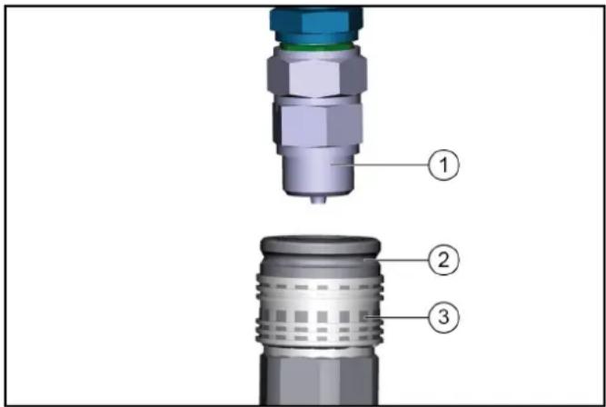
① Coupling connector
② Coupling sleeve
③ Ring
- Pull the ring of the coupling sleeve downwards and hold.
- Press the coupling connector of the attachment hydraulic hose into the coupling sleeve.
- Release the coupling ring. Check that it is securely engaged.
- To decouple, pull the ring downwards, hold it and pull out the hydraulic hose.
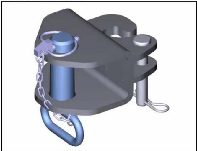
8.2 Tow bar
Note
For permissible support load and trailer load, see chapter.
8.3 Ballasting the vehicle
Note
The front axle of the vehicle must always be loaded with at least 30% of the net weight of the vehicle, and the rear axle must always be loaded with at least 30% of the net weight of the vehicle.
Before purchasing the attachment, check that these requirements are met by weighing the vehicle-attachment combination.
The following data is required for determining the total weight, the axle loads, the tyre loading capacity and the required minimum ballast:
- All weights in kg (weigh the vehicle if necessary)
All dimensions in meters (m)
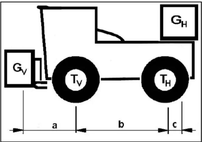
| TL (kg) = | Net | weight of the vehicle * | |
| TV (kg) = | Front axle load of the empty vehicle * | ||
| TH (kg) = | Rear axle load of the empty vehicle * | ||
| GH (kg) = | Rear ballast total weight ** | ||
| GV (kg) = | Total weight of front attachment / front ballast | ** | |
| a (m) = | Distance between front attachment (front ballast) centre of gravity and middle of front axle, max. = 0.86 m | ** *** | |
| b (m) = | Wheelbase of the vehicle * | *** | |
| c (m) = | Distance between centre of rear axle and rear ballast centre of gravity | *** | |
- See chapter "Technical data"
See operating instructions of the attachment
* Measure
8.3.1 Calculation of the minimum rear ballast for front-mounted attachments
See the manufacturer's specifications for the value "x" or use a value of x = 0.45 if no specifications are available.
$$ G _ {H \min } = \frac {G _ {V} \times a - T _ {H} \times b + x \times T _ {L} \times b}{b + c} $$
- Enter the result into the table.
8.3.2 Calculation of the actual front axle load
$$ T _ {V t a t} = \frac {G _ {V} \times (a + b) + T _ {V} \times b - G _ {H} \times C}{b} $$
- If the necessary minimum front ballast weight (GV min) is not reached with the front attachment (GV) then the weight of the front attachment must be increased to the minimum front ballast weight.
- Enter the actual calculated permissible front axle load and the permissible front axle load specified in the machine operating instructions into the table.
8.3.3 Calculation of the actual total weight
$$ G _ {t a t} = G _ {V} + T _ {L} + G _ {H} $$
- If the necessary minimum rear ballast weight (GH min) is not reached with the rear attachment (GH), then the weight of the rear attachment must be increased to the minimum rear ballast weight.
8.3.4 Calculation of the actual rear axle load
$$ T _ {H t a t} = G _ {t a t} - T _ {V t a t} $$
- Enter the result into the table.
9 Transport
9.1 Loading the vehicle
△DANGER
Risk of injury due to incorrect transport
Mind the weight of the vehicle.
Slowly and carefully drive the vehicle onto the transport vehicle.
ATTENTION
Damage to vehicle
Do not load the vehicle with the crane.
Do not use a forklift.
- Slowly drive the vehicle onto the transport vehicle.
Note
If the vehicle is not ready for running, see Chapter 9.3 Towing the vehicle.
9.1.1 Securing the vehicle
△WARNING
Danger of accident
Secure the vehicle against slipping during transport.
- Park the vehicle and prevent it from rolling away, e.g. by activating the parking brake (travel direction selector switch to NEUTRAL - Middle position)
- Secure the vehicle with a wheel retainer lashing system in accordance with valid guidelines.
9.2 Fit the transport lock
The transport is secured on the four tyres of the vehicle with the cross belts and the standard lashing straps.
CAUTION
Risk of damage
Place the straps on the wheel as close to the centre of the wheel as possible.
Do not touch or squeeze any cables.
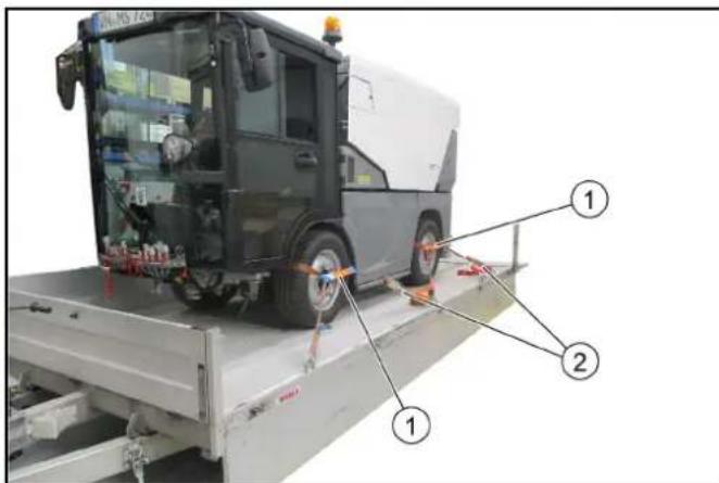
① Cross belts (4x)
② Standard safety belts (4x)
- Secure the vehicle on the four wheels as shown.
9.2.1 Laying the standard safety belt on the front wheel
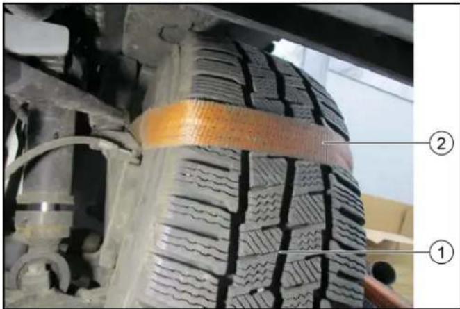
①Front wheel
② Laying the standard safety belt
1. Lay the safety belt on the front wheel as shown.
2. Attach the cross belt to the standard safety belt on the outside of the wheel.
9.2.2 Lay the standard safety belt on the rear wheel
①Rear wheel
② Laying the standard safety belt
1. Lay the safety belt on the rear wheel as shown.
2. Attach a cross belt to the standard safety belt on the outside of the wheel.
9.2.3 Lashing the vehicle down
- Hook the safety belts in the fastening eyelets and lash the vehicle down.
a Before lashing it down, check that the belts are correctly positioned on the wheel.
9.3 Towing the vehicle
CAUTION
Risk of damage due to incorrect towing
Only tow the vehicle at a walking pace and only until you are out of the hazard zone of flowing traffic. Then load the vehicle for transport.
Approach slowly and not jerkily.
Attach the tow rope or the tow bar to the towing device only.
Make sure the steering and the brake are working (only with the engine running).
In case of engine damage, release the parking brake for loading.
ATTENTION
Do not tow the vehicle if the engine is defective, the steering or brake is faulty.
①Towing device
② Towing device mount.
③ Bolt with spring pin
- Attach the towing device to the mount. Secure with bolt and spring pin.
- Attach the tow rope or tow bar to the towing device.
- In the event of engine damage, release the parking brake for loading, see chapter "Releasing the parking brake".
- Tow the vehicle out of the hazard zone and then load for transport.
10 Care and service
10.1 General notes
△DANGER
Crush hazard
When working under raised attachments, ensure these are always mechanically locked (shimming).
- Before you clean and service the vehicle, or exchange parts or adjust them to a different function, switch off the motor and remove the ignition key.
- Check if your radio is secured with a radio code before disconnecting the battery.
- Disconnect the battery before working on the electrical system.
- Repairs may only be carried out by authorised customer service centres or by qualified staff in this area who are familiar with all relevant safety instructions.
- Any welding work on the vehicle or attachments is only permitted by authorised Kärcher Customer Service.
10.2 Preparing for maintenance and cleaning work
- Park the vehicle on a level surface.
- Secure the vehicle against rolling away.
- Switch off the ignition and remove the ignition key.
10.3 Service display
The service indicator lights up when appropriate maintenance must be performed according to the inspection checklist.
The service indicator flashes in the display:
- For the first time after 50 operating hours, when the initial inspection must be carried out.
Thereafter according to the maintenance intervals according to the inspection checklist.
Note
The service indicator must be reset by Customer Service.
10.4 Maintenance intervals
Note
To preserve eligibility for warranty claims, all servicing and maintenance work during the warranty period has to be performed by an authorised Customer Service (ICL), in accordance with the inspection check list.
- Lubricate all bearings after washing the vehicle.
- The intervals for testing and maintenance (daily / weekly) by the customer / operator are listed in the chapter "Vehicle maintenance plan".
- Have the safety checks according to the applicable local regulations performed by the Customer Service department as necessary.
Further maintenance work must be carried out by the authorized Customer Service according to the inspection checklist. Please inform the Customer Service department in time.
10.5 Vehicle maintenance plan
To be performed by the operator / customer.
| Assembly Activity Daily Wee | kly | ||
| Water cooler C | clean radiator fins X | ||
| Oil cooler Clean radiator fins X | |||
| Coolant expansion reservoir | Check the coolant level X | ||
| Check the water/antifreeze mixing ratio | Check seasonally or when changing the coolant | ||
| V-belt Check for tension and wear and tear | X | ||
| Hydraulic oil tank | Check the hydraulic oil level (shown on display) | X | |
| Hydraulic couplings and connections | Check for leaks X | ||
| Hydraulic hoses | Check for leakage and damage Note Exchange the hydraulic hoses according to the inspection checklist! | X | |
| Battery poles | Check the battery poles for oxidation, brush off if necessary, and lubricate with terminal grease. Make sure the connection cables are firmly in place. | X | |
| Check the engine oil level | Check | X | |
| Brake fluid level | Check | X | |
| Cab dust filter | Check | X | |
| Tyres | Check the condition and filling pressure | X | |
| Wiping water container | Check the filling level | X | |
| Battery | Check | X | |
| Exhaust system | Visual inspection | X | |
| Lights | Check for correction function | X | |
| Engine air filter | Check / clean or replace air filter. | X | |
| Radiator grille | Cleaning | X | |
| Air-conditioner | Check and clean the radiator fins | X | |
| Parking brake | Check for correct function | X | |
| Pedals | Check for correct function | X | |
| Steering | Check for correct function | X | |
| Warning sticker | Check the legibility, replace if necessary | X | |
| Dust caps and covers for hydraulics | Check, replace if necessary | X | |
| Assembly | Activity Daily Wee | kly | |
| Screw connec-tions | Check for tightness, tighten if necessary | X | |
| Hoses and ca-ble clamps | Check | X | |
| Coolant hoses | Check | X | |
| Fuel lines and connections | Check for leaks | X | |
| Bowden ca-bles and mov-ing parts | Check for freedom of move-ment | X | |
| Electrical ca-bles | Check for damage | X | |
| Bearings / lu-brication points | Lubrication, see chapter "Ve-hicle lubrication plan" | X |
10.6 Vehicle lubrication plan
| Lubrication point | Quantity | Interval |
| Fresh water tank hinge, above | 1 Weekly | |
| Fresh water tank hinge, be- low | 1 Weekly |
10.7 Maintenance work
10.7.1Filling the wiping water container
Note
Observe the manufacturer's specifications for wiping water fluid and antifreeze. Do not mix antifreeze with other antifreeze.

①Right-hand service flap
②Lock
③ Wiping water container
- Open the right-hand service flap.
- Open the cap on the wiping water container.
- Fill with r water liquid.
a If there is a risk of frost, add antifreeze according to manufacturer's instructions.
- Close the cap on the wiping water container.
10.7.2Checking the coolant level and topping up the coolant
CAUTION
Risk of burns on account of hot components
Do not open or touch the radiator or parts of the cooling system while the motor is hot.
CAUTION
Risk of injury due to pressurised cooling system
Carefully open the expansion tank (2 levels).
ATTENTION
Material damage due to incorrect coolant
Top up the coolant only when the engine is cold.
The water/antifreeze mixing ratio should be 60:40 to 50:50.
This usually corresponds to frost protection from -25^ to -40^ .
The minimum mixing ratio should be 70:30 and the maximum mixing ratio 40:60. Further increasing the proportion of antifreeze (e.g. 30:70), does not further improve the freezing point.
The mixture of the coolant shall consist of deionised or distilled water and of radiator protection according to standards ASTM D 3306 Type 1 monoethylene glycol-based with addition of organic inhibitors.
For coolant, see chapter "Technical data".
① Right-hand service flap
②Lock
③ Expansion reservoir
- Check the filling level when the engine is cold.
- Open the right-hand service flap.
- Check the filling level in the expansion reservoir.
Note
The correct coolant level must be between MAX and MIN. In case of severe loss of coolant, carry out troubleshooting and correct any faults found.
- Top up the coolant if necessary.
Add coolant
-
Turn the cap of the expansion tank to open and remove it.
-
Add approved coolant to expansion tank to top marking (MAX).
- Fit the cap of the expansion tank and tighten.
- Close the service flap.
10.7.3Checking the hydraulic oil level and topping up the hydraulic oil
Screw-in lid with air filter
Note
Replace the air filter annually or every 1000 hours of operation
② Hydraulic oil filter
Note
May only be replaced by customer service according to the inspection checklist (ICL)
3Hydraulic oil filter
Note
May only be replaced by customer service according to the inspection checklist (ICL)
④ Hydraulic tank
- A hydraulic oil level that is too low is shown on the display.
- Top up the hydraulic oil if necessary.
Note
Lacking hydraulic oil can be topped up using a special accessory tool connected to the leakage coupling on the vehicle. If required, request the order no. at Kärcher or have Kärcher Customer Service do the topping up.
For the hydraulic oil type: See chapter "Technical data".
10.7.4Installing/removing the battery
DANGER
Risk of injury
Observe the safety instructions on the handling of batteries.
ATTENTION
Battery care
Check that the battery terminals and terminal clamps are protected with a sufficient quantity of terminal grease.
① Battery
2Plus terminal
3Minus terminal
Cover (not shown)
Installing the battery
- Fit the battery into the battery holder.
- Screw the bracket on the battery base tight.
- Connect the terminal clamp (red cable) to the plus terminal (+) .
- Connect the terminal clamp (black cable) to the minus terminal (-).
- Attach the cover.
Removing the battery
- Always disconnect the minus terminal first when removing the battery.
10.7.5Charging the battery
DANGER
Risk of injury!
Only charge the battery with the appropriate charger.
Observe the safety instructions on the handling of batteries.
Follow the operating instructions of the charger manufacturer.
- Disconnect the minus terminal at the battery.
- Connect the charger to the battery.
- Insert the mains plug and switch on the charger.
- Charge the battery with as small a charging current as possible.
- After charging, first disconnect the charger from the mains and then from the battery (minus pole first).
- Reconnect the battery.
10.7.6Cleaning and replacing air filters
The degree of contamination of the air filter is signalled by a display. The warning light will come on when the filter becomes sufficiently clogged (no rising indication such as e.g. temperature or DPF).
ATTENTION
Risk of damage to the engine
The combustion engine must be switched off to remove the air filter and when the air filter is removed.
When cleaning the air filter, make sure that no foreign matter enters the intake tube.
① Left-hand service flap
②Air filter
- Open the left-hand service flap.
① Locking hooks (4x)
② Cover
③ safety filter
4Filter insert
⑤Screw
⑥ Preliminary filter
Air filter contamination display
2. Open the locking hooks on the air filter housing.
3. Remove the air filter housing cover.
4. Open the screw and remove the preliminary filter.
5. Clean the preliminary filter with compressed air or a water jet.
6. Remove the filter inlay and safety filter.
7. Tap out both filters and clean them with an outward-directed compressed air jet, replace as needed or according to the maintenance plan.
8. Clean the interior of the air filter housing.
9. Check that the sealing surfaces and suction channels are clean and undamaged.
10.Install all cleaned filters again.
10.7.7 Changing a wheel
DANGER
Risk of fatal injury from flowing road traffic
Bring the vehicle out of the hazard zone of flowing road traffic before starting any repair work.
Switch on the warning flashers.
Erect a warning triangle.
Don warning clothing.
WARNING
Risk of injury due to sinking vehicle
Do not stand under the vehicle raised only with a jack.
CAUTION
Danger of accident
Ensure that the ground is level and solid. If necessary, place a large-scale, stable surface under the jack.
ATTENTION
Perform the wheel change only if you are familiar with the necessary steps for changing a wheel. Otherwise, seek expert assistance.
Use only suitable and undamaged tools for changing a wheel.
Use a suitable commercial jack with a lifting capacity of at least 5000kg
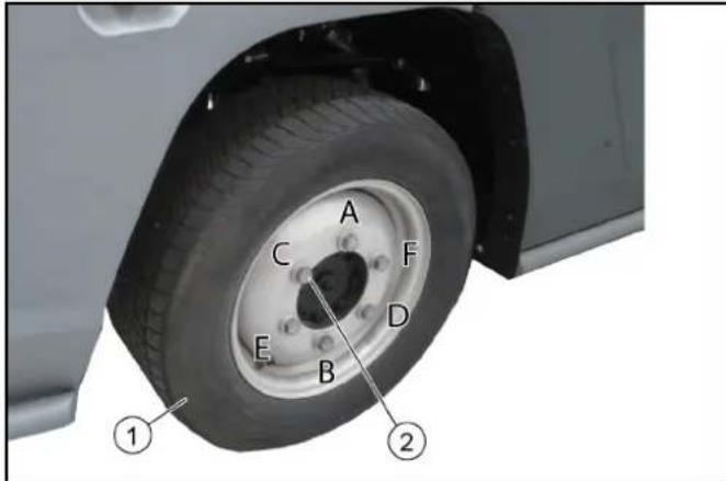
1Wheel
② Wheel bolts with washers
- Park the vehicle on level and solid ground.
- Remove the ignition key.
- Secure the vehicle against rolling away (e.g. with wheel chocks).
- Use a suitable tool to release the wheel nuts by approx. 1 turn.

- Position the jack at the jacking point and lift the vehicle.
- Additionally support the vehicle safely.
- Unscrew the wheel bolts.
- Remove the wheel.
- Clean dirty wheel bolts.
- Fit the new wheel and screw in all wheel bolts with washers all the way to the end stop, do not tighten with full torque.
-
Tighten the wheel nuts step by step in the specified sequence (A - F).
-
Lower the vehicle with the jack.
- Finally, tighten the wheel bolts in the specified sequence using a correctly working torque wrench to 330 Nm.
- Re-tighten the wheel bolts after 50 - 100 km.
10.7.8Checking/topping up the engine oil level
△CAUTION
Danger of burns
Do not touch any hot surfaces such as the exhaust pipe, SCR catalytic converter, motors or gearbox components.
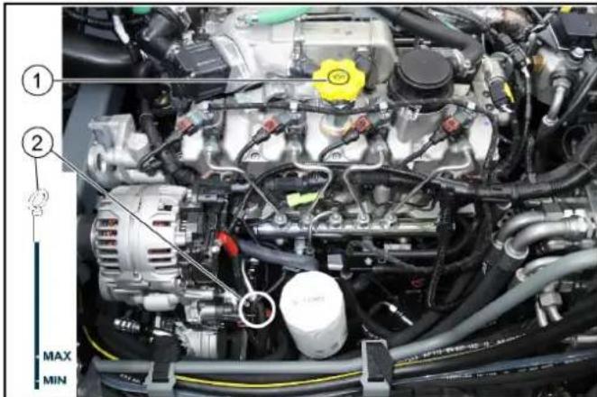
① Oil filler opening
② Oil dipstick
- Check the engine oil level only when vehicle is level.
- Bring the engine to operating temperature (70 - 80^)
- Stop the engine and wait a few minutes so that the complete oil can drain into the oil pan.
- Open the fresh water tank latch at the left (bonnet) with a square wrench.
- Pivot the fresh water tank to the side.
- Measure the oil level using the oil dipstick. If the oil level is below the lower marking (MIN), add engine oil in small steps (100 - 200ml) until the correct oil level is reached. For the correct oil type see chapter "Technical data".
10.7.9 Changing the engine oil/Engine oil filter
ATTENTION
The engine oil and engine oil filter may only be replaced by authorized Customer Service.
After every oil change, the function (calculation of the oil dilution) must be reset with a diagnostic instrument.
10.7.10Checking the brake fluid level in the reservoir
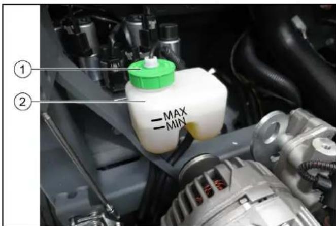
① Brake fluid reservoir
② Cap/filling hole
- Check the brake fluid level in the reservoir regularly.
- The fluid level must lie between the MIN and MAX markings.
- If the brake fluid level in the reservoir falls below MIN, the indicator light lights up.
a Top up brake fluid to MAX.
b If the indicator light lights up again after a short period of operation, have the brake system checked for leaks by an authorized Customer Service.
c Park the machine securely.
- Replacement of the brake fluid must only be carried out by the authorized Customer Service according to the inspection checklist (ICL).
10.7.11Draining the water separator
CAUTION
Danger of burns
Do not touch any hot surfaces such as the exhaust pipe, SCR catalytic converter, motors or gearbox components. If the "Water in fuel" indicator is lit, proceed as follows.
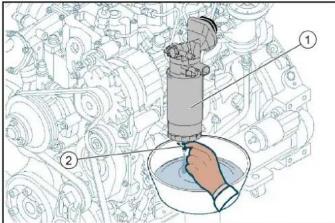
Water separator with filter
② Sensor
- Switch off the ignition and remove the ignition key.
- Allow the engine to cool sufficiently.
- Provide containers of adequate capacity.
- Unscrew the sensor on the water separator.
- Drain fuel until no more water is contained. Be careful not to spill all the fuel out of the filter in the water separator, otherwise the fuel filter must be removed, refilled and the system vented.
- Tighten the sensor again.
10.7.12Releasing the parking brake (emergency operation)
The following description only applies if the engine is not functional and no hydraulic pressure is available (e.g. for towing or loading).
△DANGER
Risk of burns from hot surfaces
Allow the vehicle to cool down before working on it.
ATTENTION
Risk of accident due to rolling away
Release the parking brake only when the vehicle is secured against rolling away.
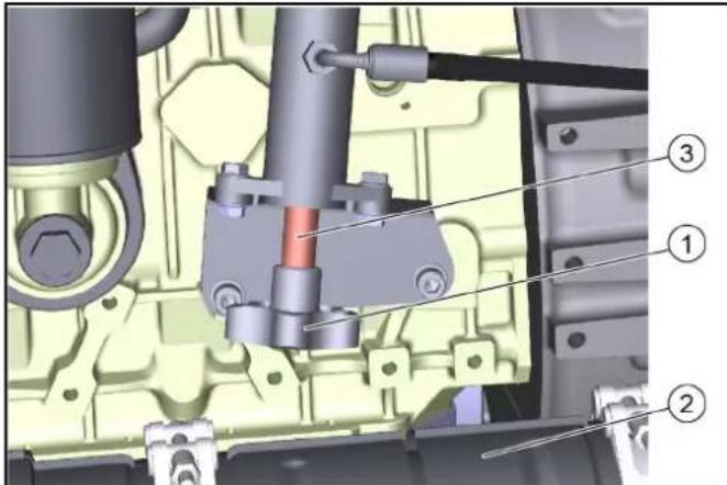
Figure: Emergency operation in position A
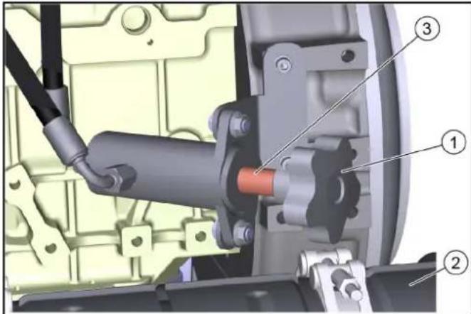
Figure: Emergency operation in position B
Screw with star-grip
② Diesel Particulate Filter
③ Sleeve
- Open the left side panel lock with the square wrench.
- Pivot the side panel outwards.
- Completely unscrew the star grip counterclockwise. Remove the sleeve.
- Turn the star grip clockwise, thereby building up the hydraulic pressure to release the parking brake.
- After towing: Unscrew the star grip completely, put the sleeve back on and tighten the star grip.
10.8 Cleaning
10.8.1 Cleaning the vehicle
Clean the vehicle daily after finishing work.
CAUTION
Risk of damage through incorrect cleaning
Do not clean joints, tyres, radiator fins, hydraulic hoses and valves, seals, electrical and electronic components using a high-pressure cleaner.
Observe the respective safety regulations when cleaning the vehicle with a high-pressure cleaner.
Do not use aggressive detergents.
Wash the vehicle only when the engine is switched off to protect the air filter.
- To avoid the risk of fire: Check the vehicle for oil and fuel leakage. Have leaks repaired by Customer Service.
- To avoid the risk of fire: Clean the engine, muffler and battery of plant residues and oil.
- If necessary, clean the engine with a brush, compressed air or with low water pressure if necessary.
- Clean the mudguards/wheel arches.
10.8.2Clean the radiator
ATTENTION
Risk of injury from sharp edges
Use protective gloves for cleaning.
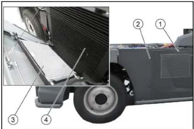
①Lock
② Right side panel
3Air-conditioner condenser
4Combination cooler
-
Charge air, water and hydraulic oil cooler
-
Release the side panel lock with a square wrench.
- Tilt the panel outwards, a safety rope holds it in position.
- Manually remove coarse dirt from the radiator.
- Use a soft brush or broom to clean with compressed air (5 bar max.) or low water pressure.
10.9 Fuses
10.9.1Fuses in the cab
The fuses in the driver's cab are located behind a cover on the middle rear wall of the cab.
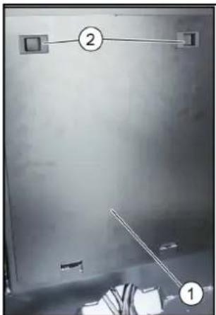
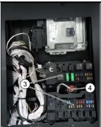
1Cover
_2 Locks
Fuses
④ Diagnostic connector
- Fold the passenger seat backrest forward.
- Open the cover latches then tilt the cover and remove it upwards.
- Replace defective fuses.
| F1 fuse MINI 15A hazard light, brake light 6.844-809.0 |
| F2 fuse MINI 10A position lamps, interior lamp 6.844-808.0 |
| F3 fuse MINI 10A spray pump 6.844-808.0 |
| F4 fuse MINI 30A screen heater 6.844-042.0 |
| F6 fuse MINI 5A fog lamp (option) 6.844-806.0 |
| F7 fuse MINI 5A position lamps left 6.844-806.0 |
| F8 fuse MINI 5A position lamps right 6.844-806.0 |
| F9 fuse MINI 10A wiper 6.844-808.0 |
| F10 fuse MINI 7.5A radio 6.844-807.0 |
| F11 fuse MINI 10A indicator 6.844-808.0 |
| F12 fuse MINI 15A beacon lamps 6.844-809.0 |
| F13 fuse MINI 5A display, rear camera 6.844-806.0 |
| F14 fuse MINI 5A BODAS ecu work hydraulics 6.844-806.0 |
| F15 fuse MINI 5A engine 6.844-806.0 |
| F17 fuse MINI 15A head lamps 6.844-809.0 |
| F18 fuse MINI 15A work lamps front 6.844-808.0 |
| F19 fuse MINI 15A cabin fan 6.844-809.0 |
| F20 fuse MINI 10A mirror heater 6.844-808.0 |
| F21 fuse MINI 10A compressor seat 6.844-808.0 |
| F22 fuse MINI 15A cabin accessors 6.844-809.0 |
| F23 fuse MINI 20A implement connector 6.844-043.0 |
| F24 fuse MINI 7.5A implement Aux 6.844-807.0 |
Note
Use only fuses with the same ampere rating.
10.9.2Fuses on the vehicle
The next fuses are located on the vehicle behind a cover on the right side panel.
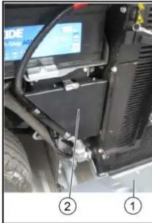
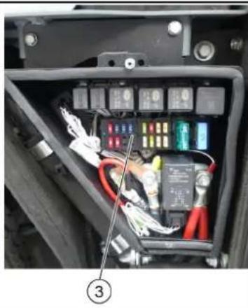
Right side panel
②Cover
Fuses
- Release the side panel lock with a square wrench.
- Tilt the panel outwards, a safety rope holds it in position.
- Open the cover latch and remove the cover.
- Replace defective fuses.
| F25 fuse MINI | 10A | engine ecu | 6.644-608.0 |
| F26 fuse MINI | 15A | engine ecu | 6.644-609.0 |
| F27 fuse MINI | 15A | engine | 6.644-609.0 |
| F28 fuse MINI | 15A | ATS (PM sensor B67) | 6.644-609.0 |
| F29 fuse MINI | 10A | ATS (NOx sensor B64) | 6.644-608.0 |
| F30 fuse MINI | 10A | ATS (NOx sensor B65) | 6.644-608.0 |
| F33 fuse MINI | 5A | radio | 6.644-606.0 |
| F34 fuse MINI | 10A | SCR (Adblue pump supply) | 6.644-608.0 |
| F35 fuse MINI | 5A | SCR | 6.644-606.0 |
| F38 fuse MINI | 5A | SCR Adblue sensor B66 | 6.644-606.0 |
| F37 fuse MINI | 20A | fuel filter heater | 6.644-043.0 |
| F38 fuse MINI | 20A | BODAS ecu drive hydraulics | 6.644-043.0 |
| F39 fuse MINI | 5A | BODAS ecu drive hydraulics | 6.644-606.0 |
| F40 fuse MINI | 5A | BODAS ecu work hydraulics | 6.644-606.0 |
| F41 fuse MAXI | 30A | BODAS ecu work hydraulics A1 | 6.644-042.0 |
| F42 fuse MAXI | 60A | glow plugs | 6.644-277.0 |
| F51 fuse MIDI | 80A | main | 7.644-031.0 |
Note
Use only fuses with the same ampere rating.
11 Storage
△WARNING
Risk of injury and damage
Be aware of the weight of the vehicle.
- Park the vehicle in a protected, level and dry place.
- If there is a danger of frost, check that there is enough antifreeze in the coolant.
- Clean the vehicle inside and out.
When stored for more than one month:
- Jack up the vehicle (freely rotating wheels).
- Disconnect the battery, recharge every 2 months.
- When restarting after prolonged storage, carry out scheduled maintenance as necessary.
12 Troubleshooting guide
You can remedy minor faults using the following overview. If in any doubt, please contact your authorised Customer Service.
△DANGER
Risk of electric shock
Switch off the vehicle before carrying out any care and maintenance work, and remove the key.
Repair work and work on electrical components must only be performed by your authorised Customer Service.
12.1 Vehicle malfunctions
| Malfunction Remedy | |
| Vehicle does not start ● | Check / charge the battery. ● Sit in the driver's seat (seat contact switch is activated). ● Set the driving direction lever to the NEUTRAL position - central position. ● Fill up fuel, bleed the fuel system. ● Check, clean and/or replace the fuel filter. ● Check the fuel connections and lines. ● Contact an authorised Customer Service department. |
| Motor running irregularly | ● Clean/replace the air filter. ● Check, clean and/or replace the fuel filter. ● Fill up fuel, bleed the fuel system. ● Check the fuel connections and lines. ● Contact an authorised Customer Service department. |
| Engine is running, but the vehicle does not drive or just slowly | ● Check the filling level of the hydraulic oil tank. ● In the event of freezing temperatures and cold hydraulic oil: Allow the vehicle to warm up for at least 3 minutes. |
12.2 Error messages for symbol displays
| Malfunction Cause Remedy | ||
| CHECK | The engine indicator light (MIL) lights up when the ignition is switched on to check the function. It notifies the driver of a fault in an emission- or safety-related component. In the event of active faults, the MIL lights up permanently. | ● If the fault is no longer active, the light is switched off after 3 driving cycles● In the event of DEF faults, the light goes out al-ready 1 driving cycle after filling up the reaction liquid (DEF)● 1 driving cycle = a Switch on the ignitionb Start the engine and let it run for at least 5 secondsc Switch off the engine and wait for the afterrun (approx. 30 seconds) |
| Engine fault in the exhaust treatment systemInforms that the exhaust aftertreatment is impaired. | ● Eliminate the error in order to get the vehicle fully functional again; this prevents damage to the engine and vehicle● Check the level in the DEF reservoir● Minimum engine run time after topping up is 20 minutes. Then the warning lamp goes out. | |
| Regeneration process required. | ● Perform regeneration (see chapter "Regenera-tion"). | |
| Regeneration process has generated an error (NOx monitoring unit). | ● Call Customer Service. | |
| Engine oil pressure is too high. | ● Call Customer Service. | |
| Fault in the drive. ● Call Customer Service. | ||
| Parking brake active. ● Release the | parking brake. | |
| Low fuel level. ● Top up the fuel. | ● Vent the fuel system if the tank was run dry. | |
| Coolant temperature is too high. ● Switch off the motor.● Clean the radiator (see chapter "Cleaning the ra-diator").● Check the level of coolant in the motor, refill as necessary.● If the warning light does not go out within 5 min-utes:a Switch off the engineb Contact Customer Service | ||
| Hydraulic oil temperature too high. | ● Operate the engine in idling mixture until the warning light goes out. | |
| Hydraulic oil level is too low. | ● Top up the hydraulic oil. | |
| Hydraulic oil temperature too low. | ● Carefully warm up the engine until the warning light goes out. | |
| Hydraulic oil filter malfunction | ● Filter dirty or oil too highly viscous (viscous)● Heat the hydraulic oil to at least 40°C by operating the vehicle. If the fault is still active: Contact Ser-vice. | |
| Service required. | ● Have the device serviced by Customer Service.a The service display must be reset by Customer Service. | |
13 Technical data
| Device performance data | ||
| Travel speed km/h 20, 25, 30, 40, 50, 60 | The speed may be limited depending on the variant and country specific requirements. The limitation is secured by software. | |
| Travel speed, backwards km/h 20 | ||
| Working speed km/h 20 | ||
| Working speed (max.) km/h 40 / winter | ||
| Climbing ability (max.) % 25 | ||
| Turning circle m 2,06 (Dwi) | ||
| Electrical system / battery | ||
| Battery type - Maintenance-free | ||
| Working voltage of the battery V | 12 | |
| Battery capacity | Ah | 105 |
| Dimensions and weights | ||
| Length | mm | 4.248 +/- 30 |
| Width | mm | 1.300 |
| Height | mm | 1.990 +10/-20 |
| Net weight (transport weight) | kg | 2500-2800 (depending on the equipment as a tractor) |
| Approved total weight | kg | 6000 |
| Maximum permissible front axle load | kg | 2700 |
| Maximum permissible rear axle load | kg | 3300 |
| Trailer coupling vertical load | kg | 300 |
| Trailer load, inertia-braked | kg | 3000 |
| Unbraked trailer load | kg | 750 |
| Permissible inertia-unbraked total gross weight | kg | 9000 |
| Permissible unbraked total gross weight | kg | 6750 |
| Operating materials | ||
| Fuel type | Diesel (in accordance with DIN EN 590) BIODIESEL can be mixed up to 7% (according to UNI EN 14214) | |
| Fuel tank capacity | 70 | |
| Engine oil type | Shell Rimula R6 LM (ACEA E6 - SAE 10W-40) | |
| Engine oil volume | l | 13,2 |
| Type of coolant | Glysantin G 40 (ASTM D 3306) | |
| Amount of coolant | l | 14 |
| Type of hydraulic oil | Renol B HV 46 (ISO 11158) | |
| Hydraulic oil quantity | l | 55 |
| Grease | EP lithium soaps (NLGI 2) Observe the lubrication point symbols on the device | |
Subject to technical modifications.
13.1 Technical data of engines
13.2 Tyres
| Engine type VM R754EU6C (Euro 6) VM R754I SE5 (Stage V) | |||
| Type Four-cylinder 4-stroke | diesel en- | engine DPF and SCR system | Four-cylinder 4-stroke diesel engine DPF system |
| Cooling type Water cooling | Water cooling | ||
| Engine capacity cm | 3 | 2970 2970 | |
| Engine performance kW/PS 75 / 102 54.5 / 74 | |||
| Engine speed 1/min | 2300 2300 | ||
| Noise at the driver's ear ac-cording to Regulation (EU) 1322/2014, App. XIII | dB(A) | 73 (closed) 79 (open) | 73 (closed) 79 (open) |
| Vibration value, whole body, according to VO (EU) 1322/2014, App. XIV | m/s² | 1 Seat Grammer MSG75GL/522: - 1.22 (light driver) - 1.01 (heavy driver) 2 Seat Cobo SC47M-M200: - 1.15 (light driver) - 0.91 (heavy driver) 3 Seat König K210MVGL-P350-W2: - 1.16 (light driver) - 1.03 (heavy driver) | 1 Seat Grammer MSG75GL/522: - 1.22 (light driver) - 1.01 (heavy driver) 2 Seat Cobo SC47M-M200: - 1.15 (light driver) - 0.91 (heavy driver) 3 Seat König K210MVGL-P350-W2: - 1.16 (light driver) - 1.03(heavy driver) |
| Kenda235/65R 16C KR33A | Reference axle load1450 kg | Maximum axle load3300 kg |
| Tyre inflation pressure front axle + rear axle in kPa (bar) | 550 (5.5) | 680 (6.8) |
| Michelin235/65R 16C 121/119R M+S Agilis Alpin | Reference axle load1450 kg | Maximum axle load3300 kg |
| Tyre inflation pressure front axle + rear axle in kPa (bar) | 550 (5.5) | 670 (6.7) |
Contenu
6.3 Raccordements hydrauliques
Terminologie PTO hydraulique
Power Take Off = Force hydraulique généree
Terminologie AUX
① Fenetre coulissante (2 parties)
| F1 fuse MINI 15A hazard light, brake light 6.644-809.0 |
| F2 fuse MINI 10A position lamps, interior lamp 6.644-808.0 |
| F3 fuse MINI 10A spray pump 6.644-808.0 |
| F4 fuse MINI 30A screen heater 6.644-042.0 |
| F6 fuse MINI 5A fog lamp (option) 6.644-806.0 |
| F7 fuse MINI 5A position lamps left 6.644-806.0 |
| F8 fuse MINI 5A position lamps right 6.644-806.0 |
| F9 fuse MINI 10A wiper 6.644-808.0 |
| F10 fuse MINI 7.5A radio 6.644-807.0 |
| F11 fuse MINI 10A indicator 6.644-808.0 |
| F12 fuse MINI 15A beacon lamps 6.644-808.0 |
| F13 fuse MINI 5A display, rear camera 6.644-806.0 |
| F14 fuse MINI 5A BODAS ecu work hydraulics 6.644-806.0 |
| F15 fuse MINI 5A engine 6.644-806.0 |
| F17 fuse MINI 15A head lamps 6.644-809.0 |
| F18 fuse MINI 15A work lamps front 6.644-809.0 |
| F19 fuse MINI 15A cabin fan 6.644-809.0 |
| F20 fuse MINI 10A mirror heater 6.644-808.0 |
| F21 fuse MINI 10A compressor seat 6.644-806.0 |
| F22 fuse MINI 15A cabin accessors 6.644-809.0 |
| F23 fuse MINI 20A implement connector 6.644-043.0 |
| F24 fuse MINI 7.5A implement Aux 6.644-807.0 |
Remarque
| F25 fuse MINI | 10A | engine ecu | 6.644-608.0 |
| F26 fuse MINI | 15A | engine ecu | 6.644-609.0 |
| F27 fuse MINI | 15A | engine | 6.644-609.0 |
| F28 fuse MINI | 15A | ATS (PM sensor B67) | 6.644-609.0 |
| F29 fuse MINI | 10A | ATS (NOx sensor B64) | 6.644-608.0 |
| F30 fuse MINI | 10A | ATS (NOx sensor B65) | 6.644-608.0 |
| F33 fuse MINI | 5A | radio | 6.644-606.0 |
| F34 fuse MINI | 10A | SCR (Adblue pump supply) | 6.644-608.0 |
| F35 fuse MINI | 5A | SCR | 6.644-606.0 |
| F36 fuse MINI | 5A | SCR Adblue sensor B66 | 6.644-606.0 |
| F37 fuse MINI | 20A | fuel filter heater | 6.644-043.0 |
| F38 fuse MINI | 20A | BODAS ecu drive hydraulics | 6.644-043.0 |
| F39 fuse MINI | 5A | BODAS ecu drive hydraulics | 6.644-606.0 |
| F40 fuse MINI | 5A | BODAS ecu work hydraulics | 6.644-606.0 |
| F41 fuse MAXI | 30A | BODAS ecu work hydraulics A1 | 6.644-042.0 |
| F42 fuse MAXI | 60A | glow plugs | 6.644-277.0 |
| F51 fuse MIDI | 80A | main | 7.644-031.0 |
Remarque
| F1 fuse MINI 15A hazard light, brake light 6.644-809.0 |
| F2 fuse MINI 10A position lamps, interior lamp 6.644-808.0 |
| F3 fuse MINI 10A spray pump 6.644-808.0 |
| F4 fuse MINI 30A screen heater 6.644-042.0 |
| F6 fuse MINI 5A fog lamp (option) 6.644-806.0 |
| F7 fuse MINI 5A position lamps left 6.644-806.0 |
| F8 fuse MINI 5A position lamps right 6.644-806.0 |
| F9 fuse MINI 10A wiper 6.644-808.0 |
| F10 fuse MINI 7.5A radio 6.644-807.0 |
| F11 fuse MINI 10A indicator 6.644-808.0 |
| F12 fuse MINI 15A beacon lamps 6.644-808.0 |
| F13 fuse MINI 5A display, rear camera 6.644-806.0 |
| F14 fuse MINI 5A BODAS ecu work hydraulics 6.644-806.0 |
| F15 fuse MINI 5A engine 6.644-806.0 |
| F17 fuse MINI 15A head lamps 6.644-809.0 |
| F18 fuse MINI 15A work lamps front 6.644-809.0 |
| F19 fuse MINI 15A cabin fan 6.644-809.0 |
| F20 fuse MINI 10A mirror heater 6.644-808.0 |
| F21 fuse MINI 10A compressor seat 6.644-806.0 |
| F22 fuse MINI 15A cabin accessors 6.644-809.0 |
| F23 fuse MINI 20A implement connector 6.644-043.0 |
| F24 fuse MINI 7.5A implement Aux 6.644-807.0 |
Nota
| F25 fuse MINI | 10A | engine ecu | 6.644-608.0 |
| F26 fuse MINI | 15A | engine ecu | 6.644-609.0 |
| F27 fuse MINI | 15A | engine | 6.644-609.0 |
| F28 fuse MINI | 15A | ATS (PM sensor B67) | 6.644-609.0 |
| F29 fuse MINI | 10A | ATS (NOx sensor B64) | 6.644-608.0 |
| F30 fuse MINI | 10A | ATS (NOx sensor B65) | 6.644-608.0 |
| F33 fuse MINI | 5A | radio | 6.644-606.0 |
| F34 fuse MINI | 10A | SCR (Adblue pump supply) | 6.644-608.0 |
| F35 fuse MINI | 5A | SCR | 6.644-606.0 |
| F38 fuse MINI | 5A | SCR Adblue sensor B66 | 6.644-606.0 |
| F37 fuse MINI | 20A | fuel filter heater | 6.644-043.0 |
| F38 fuse MINI | 20A | BODAS ecu drive hydraulics | 6.644-043.0 |
| F39 fuse MINI | 5A | BODAS ecu drive hydraulics | 6.644-606.0 |
| F40 fuse MINI | 5A | BODAS ecu work hydraulics | 6.644-606.0 |
| F41 fuse MAXI | 30A | BODAS ecu work hydraulics A1 | 6.644-042.0 |
| F42 fuse MAXI | 60A | glow plugs | 6.644-277.0 |
| F51 fuse MIDI | 80A | main | 7.644-031.0 |
Nota
7 Cabina de conductor
7.1 Puertas
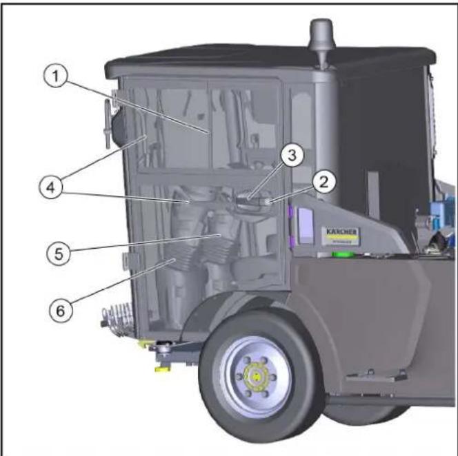
| F1 fuse MINI 15A hazard light, brake light 6.644-609.0 |
| F2 fuse MINI 10A position lamps, interior lamp 8.644-608.0 |
| F3 fuse MINI 10A spray pump 6.644-608.0 |
| F4 fuse MINI 30A screen heater 6.644-042.0 |
| F6 fuse MINI 5A fog lamp (option) 6.644-606.0 |
| F7 fuse MINI 5A position lamps left 6.644-606.0 |
| F8 fuse MINI 5A position lamps right 6.644-606.0 |
| F9 fuse MINI 10A wiper 6.644-608.0 |
| F10 fuse MINI 7.5A radio 6.644-607.0 |
| F11 fuse MINI 10A indicator 6.644-608.0 |
| F12 fuse MINI 15A beacon lamps 6.644-608.0 |
| F13 fuse MINI 5A display, rear camera 6.644-606.0 |
| F14 fuse MINI 5A BODAS ecu work hydraulics 6.644-606.0 |
| F15 fuse MINI 5A engine 6.644-606.0 |
| F17 fuse MINI 15A head lamps 6.644-609.0 |
| F18 fuse MINI 15A work lamps front 6.644-609.0 |
| F19 fuse MINI 15A cabin fan 6.644-609.0 |
| F20 fuse MINI 10A mirror heater 6.644-608.0 |
| F21 fuse MINI 10A compressor seat 6.644-608.0 |
| F22 fuse MINI 15A cabin accessors 6.644-609.0 |
| F23 fuse MINI 20A implement connector 6.644-043.0 |
| F24 fuse MINI 7.5A implement Aux 6.644-607.0 |
Nota
| F25 fuse MINI | 10A | engine ecu | 6.644-608.0 |
| F26 fuse MINI | 15A | engine ecu | 6.644-609.0 |
| F27 fuse MINI | 15A | engine | 6.644-609.0 |
| F28 fuse MINI | 15A | ATS (PM sensor B67) | 6.644-609.0 |
| F29 fuse MINI | 10A | ATS (NOx sensor B64) | 6.644-608.0 |
| F30 fuse MINI | 10A | ATS (NOx sensor B65) | 6.644-608.0 |
| F33 fuse MINI | 5A | radio | 6.644-606.0 |
| F34 fuse MINI | 10A | SCR (Adblue pump supply) | 6.644-608.0 |
| F35 fuse MINI | 5A | SCR | 6.644-606.0 |
| F36 fuse MINI | 5A | SCR Adblue sensor B66 | 6.644-606.0 |
| F37 fuse MINI | 20A | fuel filter heater | 6.644-043.0 |
| F38 fuse MINI | 20A | BODAS ecu drive hydraulics | 6.644-043.0 |
| F39 fuse MINI | 5A | BODAS ecu drive hydraulics | 6.644-606.0 |
| F40 fuse MINI | 5A | BODAS ecu work hydraulics | 6.644-606.0 |
| F41 fuse MAXI | 30A | BODAS ecu work hydraulics A16 | 6.644-042.0 |
| F42 fuse MAXI | 60A | glow plugs | 6.644-277.0 |
| F51 fuse MIDI | 80A | main | 7.644-031.0 |
Nota
Garanta uma boa ventilação aoOOTI 1000000000000000000000000000000000000000000000000000000000000000000000000000000000000
7 Cabina do conductor
7.1 Portas

7.8 Consola no banco do conductor
6.2 Ajustar o banco do conductor
PERIGO
Perigo de acidente
① Banco do conductor
② Ajuste horizontal
10.7.7Mudar as rodas
PERIGO
Perigo de vida devido aoTRSito
10.9.1Fusiveis na cabina do conductor
| F1 fuse MINI 15A hazard light, brake light 6.644-809.0 |
| F2 fuse MINI 10A position lamps, interior lamp 6.644-808.0 |
| F3 fuse MINI 10A spray pump 6.644-808.0 |
| F4 fuse MINI 30A screen heater 6.644-042.0 |
| F6 fuse MINI 5A fog lamp (option) 6.644-806.0 |
| F7 fuse MINI 5A position lamps left 6.644-806.0 |
| F8 fuse MINI 5A position lamps right 6.644-806.0 |
| F9 fuse MINI 10A wiper 6.644-808.0 |
| F10 fuse MINI 7.5A radio 6.644-807.0 |
| F11 fuse MINI 10A indicator 6.644-808.0 |
| F12 fuse MINI 15A beacon lamps 6.644-808.0 |
| F13 fuse MINI 5A display, rear camera 6.644-806.0 |
| F14 fuse MINI 5A BODAS ecu work hydraulics 6.644-806.0 |
| F15 fuse MINI 5A engine 6.644-806.0 |
| F17 fuse MINI 15A head lamps 6.644-809.0 |
| F18 fuse MINI 15A work lamps front 6.644-809.0 |
| F19 fuse MINI 15A cabin fan 6.644-809.0 |
| F20 fuse MINI 10A mirror heater 6.644-808.0 |
| F21 fuse MINI 10A compressor seat 6.644-806.0 |
| F22 fuse MINI 15A cabin accessors 6.644-809.0 |
| F23 fuse MINI 20A implement connector 6.644-043.0 |
| F24 fuse MINI 7.5A implement Aux 6.644-807.0 |
Aviso
| F25 fuse MINI | 10A | engine ecu | 6.644-608.0 |
| F26 fuse MINI | 15A | engine ecu | 6.644-609.0 |
| F27 fuse MINI | 15A | engine | 6.644-609.0 |
| F28 fuse MINI | 15A | ATS (PM sensor B67) | 6.644-609.0 |
| F29 fuse MINI | 10A | ATS (NOx sensor B64) | 6.644-608.0 |
| F30 fuse MINI | 10A | ATS (NOx sensor B65) | 6.644-608.0 |
| F33 fuse MINI | 5A | radio | 6.644-606.0 |
| F34 fuse MINI | 10A | SCR (Adblue pump supply) | 6.644-608.0 |
| F35 fuse MINI | 5A | SCR | 6.644-606.0 |
| F36 fuse MINI | 5A | SCR Adblue sensor B66 | 6.644-606.0 |
| F37 fuse MINI | 20A | fuel filter heater | 6.644-043.0 |
| F38 fuse MINI | 20A | BODAS ecu drive hydraulics | 6.644-043.0 |
| F39 fuse MINI | 5A | BODAS ecu drive hydraulics | 6.644-606.0 |
| F40 fuse MINI | 5A | BODAS ecu work hydraulics | 6.644-606.0 |
| F41 fuse MAXI | 30A | BODAS ecu work hydraulics A16 | 6.644-042.0 |
| F42 fuse MAXI | 60A | glow plugs | 6.644-277.0 |
| F51 fuse MIDI | 80A | main | 7.644-031.0 |
Aviso
Variant besturing links
| F1 fuse MINI 15A hazard light, brake light 6.644-609.0 |
| F2 fuse MINI 10A position lamps, interior lamp 6.644-608.0 |
| F3 fuse MINI 10A spray pump 6.644-608.0 |
| F4 fuse MINI 30A screen heater 6.644-042.0 |
| F6 fuse MINI 5A fog lamp (option) 6.644-606.0 |
| F7 fuse MINI 5A position lamps left 6.644-606.0 |
| F8 fuse MINI 5A position lamps right 6.644-606.0 |
| F9 fuse MINI 10A wiper 6.644-608.0 |
| F10 fuse MINI 7.5A radio 6.644-607.0 |
| F11 fuse MINI 10A indicator 6.644-608.0 |
| F12 fuse MINI 15A beacon lamps 6.644-608.0 |
| F13 fuse MINI 5A display, rear camera 6.644-606.0 |
| F14 fuse MINI 5A BODAS ecu work hydraulics 6.644-606.0 |
| F15 fuse MINI 5A engine 6.644-606.0 |
| F17 fuse MINI 15A head lamps 6.644-609.0 |
| F18 fuse MINI 15A work lamps front 6.644-609.0 |
| F19 fuse MINI 15A cabin fan 6.644-609.0 |
| F20 fuse MINI 10A mirror heater 6.644-608.0 |
| F21 fuse MINI 10A compressor seat 6.644-608.0 |
| F22 fuse MINI 15A cabin accessors 6.644-609.0 |
| F23 fuse MINI 20A implement connector 6.644-043.0 |
| F24 fuse MINI 7.5A implement Aux 6.644-607.0 |
Instructie
| F25 fuse MINI | 10A | engine ecu | 6.644-608.0 |
| F26 fuse MINI | 15A | engine ecu | 6.644-609.0 |
| F27 fuse MINI | 15A | engine | 6.644-609.0 |
| F28 fuse MINI | 15A | ATS (PM sensor B67) | 6.644-609.0 |
| F29 fuse MINI | 10A | ATS (NOx sensor B64) | 6.644-608.0 |
| F30 fuse MINI | 10A | ATS (NOx sensor B65) | 6.644-608.0 |
| F33 fuse MINI | 5A | radio | 6.644-606.0 |
| F34 fuse MINI | 10A | SCR (Adblue pump supply) | 6.644-608.0 |
| F35 fuse MINI | 5A | SCR | 6.644-606.0 |
| F38 fuse MINI | 5A | SCR Adblue sensor B66 | 6.644-606.0 |
| F37 fuse MINI | 20A | fuel filter heater | 6.644-043.0 |
| F38 fuse MINI | 20A | BODAS ecu drive hydraulics | 6.644-043.0 |
| F39 fuse MINI | 5A | BODAS ecu drive hydraulics | 6.644-606.0 |
| F40 fuse MINI | 5A | BODAS ecu work hydraulics | 6.644-606.0 |
| F41 fuse MAXI | 30A | BODAS ecu work hydraulics A1 | 6.644-042.0 |
| F42 fuse MAXI | 60A | glow plugs | 6.644-277.0 |
| F51 fuse MIDI | 80A | main | 7.644-031.0 |
Instructie
13.2 Bandenuitrusting
| Kenda235/65R 16C KR33A | Referentie asbelasting1450 kg | Maximale asbelasting3300 kg |
| Bandenspanning vooras +chteras in kPa (bar) | 550 (5,5) | 680 (6,8) |
| Michelin235/65R 16C 121/119R M+S Agilis Alpin | Referentie asbelasting1450 kg | Maximale asbelasting3300 kg |
| Bandenspanning vooras +chteras in kPa (bar) | 550 (5,5) | 670 (6,7) |
περιχόμενα
1 Tevikéc unoideiEic 273
1.1 Eioaywn 273
1.2 PapaotEoC EoTIAOuOc 273
1.2.1 Eλεγxος παράδοσης 273
1.2.2IapadotoeC EoTIAO MC 250 273
1.2.3 207nma eTtEepyaoiafkauaepiwv (ATS) 273
1.3 Eyyunon 273
1.4 Papελκόνενα και ανταλλακικά 273
2 PpOeTOpEyn Xpnon 273
2.1 Baoioko npxavnu 274
2.2 PpoBaeun Aaveoaeyn xpno 274
3 PpOoTaia Tou TepiBaalovtos 274
3.1 Atoouon 274
3.2 Atoaupon evoc axpnoTeuEvou oxnauo.. 274
4YnoeieEic aoeaiaos 274
4.1 i kivovuvv 274
4.2 i UTOEIEEIG aOaAeIac 274
4.3 YTROEiEIGaOgpaAeiaG yia Tnv kivon 274
4.4 YTIOEIEEIGA OoPAAEIAI TETPEAOIKIVTNpW 275
4.5 YTROEiEIGaOpaAeiaG yia n Tepopap 275
4.6 YrroEieic aopaaiai yia povtiba kai ouvtnpn... 275
4.7 Eππλεον Uτθεδεις ασφαλείας γι ηλειουργία.... 275
4.8 Εεση των πινακίδων εργοστασίου 275
4.9 Θεση αριθμού πλαισίου (VIN) 276
4.10 276
4.11 Θεαη των συμβολων στο ὄχημα 277
4.12 Suotmuata aospaaleias 277
4.12.1 Φpayη εκκινησς 277
4.12.2 Ⅱakontns επaφης kaθioμatoς 277
4.12.3Φevoakivntroioans 278
4.12.4 Kauniva ooyou 278
5 Mntatapie / oopTIOTeC 278
5.0.1 TPOEIOIOTNOEw 278
5.0.2 YIIOBcEIEc aOaPaeiaac 278
6 Euovotikn napouiaon oxuatoC 279
6.1 Oyn aio Eeprocs 279
6.2 Oyn aio nio 279
6.3 Yopauaikec auvdeoeic 279
6.3.1 Yopauaike souvdeoi, eptos 279
6.3.2 Yopauaikeouvoeoi 280
6.4 ETeevduoEic 280
7 Kapiniva obnyou 280
7.1 IopTeC 280
7.2ΦIATPO EoWTePIKou Xwpou 281
7.3 Paδióφωvo 281
7.4 Suotoiia iiaokottwv 281
7.5 Εερμανη, αερισός, σύοτημα κλιμαπισμου 281
7.5.1 Autopatoc kaiptiooC (TpoaipETIKO) 282
7.6 EoTepiKoC oTioaOc 282
7.7 Σκιδio 283
7.8 KovoOa aTo kaTeiogpa ooyou 283
7.8.1 AiaKoTTns pEa e aTouovwoons mTaapiaac 283
7.9 KovoIa TIOVIOU 283
7.9.1 Pioauiaikokntns 283
7.9.2 Diakottns kateuovonkivonss 284
7.9.3 Kλειδαρία μιζας 284
7.10 IVrA 284
7.10.1 Ievtai ykaiou 284
7.10.2 IVrAa 284
7.10.3Φpevoakivntroinons 285
7.11 Obovni 285
7.11.1 Nktpa Aitoupyiw /puoioeow 285
7.11.2 EvdiEiOeovnσTn λεitoupyia Ekkivno n/ μεταφopac 285
7.11.3 Evéiéic oóvns σπ λειουργia εργασίας 285
7.11.4 Eπλογη δηγησς (2/4 τροχών) 286
7.11.5 Kαερα σισθοπρείας 286
7.11.6 i a k o i a c 286
7.11.7 286
4 Kovoalexepipou 289
4.1 KovoAoXeipioou oTo UTOBpaXiovio 289
4.1.1 Avtiotoixion 8aikou uynxavnatoos 289
5 O8ovn. 289
5.1 Mevou agptnmuTowv 290
5.2 Mevou Puθμioεiç 290
5.2.1 Ppaayataoioiog npuoiov oovns 290
5.2.2 PpOBoAn PAnpoopopiwv OoTnmuToC 290
5.2.3 DPF (piaTpo oWmuTioiw vtiελ) 291
5.3 Mevou Suvtipnog 291
5.4 MevoAUX (EKTovwot Tnv TIEoT tou ubpauiKou .) 291
6 Θεση σε λειτουργία 291
6.1 Eλεγχος ασαφαείας πριν από την εκκίνηση... 291
6.1.1 'EeYxoc aqaaieiac oTo Baaiko uXavnua 291
6.2 Puroiion Kaiiparoc oBnyou 292
6.3 Puroian Theon Tiooviou 293
6.4 Avεφδiαμός 293
6.4.1 PoooRknaou 293
6.4.2 IpoooIkn DEF n AdBlue 293
7 Aetoupyia 293
7.1 OI 10 / 50 / 100 ( ) 294
7.2Φevoakivntoioiogns 294
7.3 Aetoupyia oohnyancs 294
7.3.1 EkkivnoKivnTnpa 294
7.3.2 ETIaoyn KATEUuvoans kivnoans 294
7.3.3 Kivnon 294
7.3.4 Tdoon 294
7.3.5 Kλειδωμα διαφορικό (ειδικός εξοπτλισός) 295
7.3.6 Tempomat 295
7.3.7 Σταθμενοι on oxηματος 295
7.4 Aiaikaoia avaawoyovnOg oXmuata μe iAtpo vTcEλ (DPF) 295
7.4.1 Xeipokivtn avaωoyovnon 295
7.4.2 Autouan avaovoyon 296
7.5 Xειερίνη χρήση 296
7.5.1 Avitayetikn Tpoostaia 296
8PiOoTeEs OUsKEuEs 296
8.1 SuVbEaTn TpOaTeW vuaKeuW uTo oxna 296
8.2Korostopoc 297
8.3Too0eTnOaVtIbapwOTo oxna 297
8.3.1 YIIOAOYIOUOS TUV EALXIOATWV TIOW AVITIAPWV ME TPoO0IECS TPOO0ETECS OOUKEUECS 297
8.3.2 YItoLoyioIoc Tou IppaymuAtIKou φoptiou MIIpoostivou áOva 297
8.3.3 YToIoYoIaOIs Tou TpaayAtIKo uvoIAKoBapouc.. 297
8.3.4 YItoLoyioiOoC tou IIpaTuKoi oopriou Tiow aGova 297
9 Metaopá 297
9.1ΦoPfwon oxμatoC 297
9.1.1 Aospaian oxmuos 297
9.2 ToToTeTnToaσφαλειας μεταφορας 298
9.2.1 ToTOnTeToTovTuTnIOIaVtAoQaAiaCStov TPOOTIVoTPOXo 298
9.2.2 ToTIOeTeToV TUtIKo IaVTA aOpaAeiac OToV Tiow TpoxO 298
9.2.3 Pnpoeoesson tou oxetaoc 298
9.3 Ppuouknoon oxmuato 298
10Φovriδa kai ouvtipnoi 299
10.1 Tevikc UToDeiEeIc 299
10.2IpoeToiaoaεpyaovouvtnpnnckaiKaαapaou 299
10.3 EvoiEiEg oepBis 299
10.4 Xpoviká δiaotημata ouvtnpnσç 299
10.5 xEio ouvtnpnOxmuo 300
10.6 x loiTavoc oxmuo 301
10.7 Epyaioes ouvtnpnons 301
10.7.1 PAnpwn Doxieou vepou nuaon 301
10.7.2 ELeyXoS Oaθmns yukTKOu μeou kai 301
10.7.3 EAEyXoC OaOaUpiPwOn Upaauikou Aoiu 302
10.7.4 TtooTeTn/opaipεση μταπapiac 302
10.7.5ΦoPTiOg μTatapiaC 302
10.7.6 Kaopio6 kaai alayn iipou aepa 302
10.7.7 AvtikataoTaon Tpoxou 303
10.7.8 Eλεγxος σταθμης λαδιού κινητήρα / προσθήκη λαδιού 304
10.7.9 Alambdayn i o u Kivntnpa /piaipou i o u 304
10.7.10 ELeyXos OraTeunsg uypou opevwoTo doxio 304
10.7.11 Ekkewon diaxomegaTn vepou 304
10.7.12 Auaioo xieipoppevou (evepytoiOnn EktaKtnc avaykn) 305
10.8Kaθαρισμός 305
10.8.1 Kaapioos oxipato 305
10.8.2 Kaopioosuyeiou 305
10.9 Aospaaleie 306
10.9.1 Aopaaeeic otnv kauniva 306
10.9.2 Aopaaaleics oTo oxma 306
11 Atoeikcuon 307
12 Avrietwnn 307
12.1 Bαβες στο ὄχημα 307
12.2 Mnuμata σαλμatoc Σην ενδειη Σμβóλou 307
13 TeXviKa XapakTnpiOtiKa 309
13.1 TeXViKa xaapaktnpiotikka kivnnpwv 310
13.2 Eλaσικα 310
Tevikc urodeige
1.1 Eiogaywyn
Pniv ano Tnv npwn xpnoTou oxmuoc oac, diaaote autec Tc yvnoies odnyie cxponnc kai Tc utodieic aopaaiaac. Eapmuocetre autc ts odnyiec.
1.2.1 ELeyXoc npadooons
Kata nTv npadoon Tou oxnmuoc dnawte aeeowc stov Emuopo h Tov avTTPOoWTOUXOV cHc atto TN eTAPopa kai EAATTwata Tou diATIOTOWate.
1.2.2 NapaBorEoC EoiAio MC 250
Ta TapaKaTAtOxHmuata TepiypapovTai e autoTo ExyEpiDIO Aietoupyia:
Baoikó μnxávnμα με κivntnpa VM (R754EU6C) 75 kW (Euro 6)
H Karcher Tpooepe1 3 npaaayc kaiomuatuw ohyou:
KαθισμαKonig K210MVGL-P350-W2
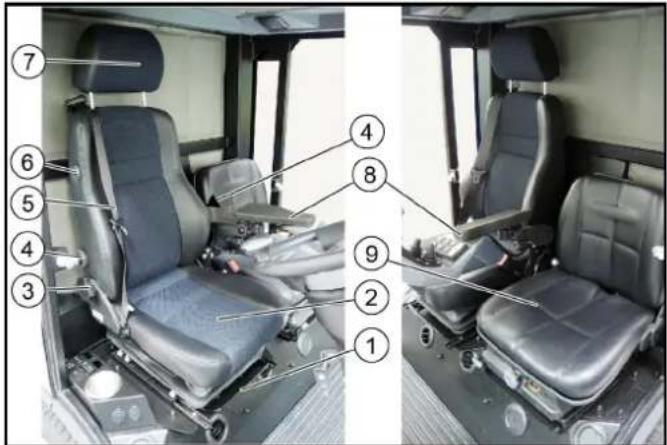
Opovia puOuian Tpuoui npaBnEtoVooTPOC ta EAAW
② Kaθioμa oδnyou tVεuμaTiknç avaptnon
③ P'θμiən kλiənç πλaɪnts kaθiσμaτος
Pouian oospuiiknc utooTnpiEgns (TpooTaia aTo Tn lopsoon)
⑥ Zwyn aopaaeias
⑥ Diakontns EepaovnKaioaato
②Σπρiγμακεφαλης
Tia puOuian uouc TpaBnTe TTPOC Ta EeW n OTPwEe TPOC Ta eOa
⑧ YIIOBpaXIOVIOE KOVoOaEλEyxou
Káθioμα ouvεπβαtn (TPOaIPεTIKá)
Káθiασα Cobo SC47M-M200 (εμφαviζεται χωρις uτοβραχίονι)

Toroemote to npoeidomoinikpinywo.
| F1 fuse MINI 15A hazard light, brake light 6.644-809.0 |
| F2 fuse MINI 10A position lamps, interior lamp 6.644-808.0 |
| F3 fuse MINI 10A spray pump 6.644-808.0 |
| F4 fuse MINI 30A screen heater 6.644-042.0 |
| F6 fuse MINI 5A fog lamp (option) 6.644-806.0 |
| F7 fuse MINI 5A position lamps left 6.644-806.0 |
| F8 fuse MINI 5A position lamps right 6.644-806.0 |
| F9 fuse MINI 10A wiper 6.644-808.0 |
| F10 fuse MINI 7.5A radio 6.644-807.0 |
| F11 fuse MINI 10A indicator 6.644-808.0 |
| F12 fuse MINI 15A beacon lamps 6.644-808.0 |
| F13 fuse MINI 5A display, rear camera 6.644-806.0 |
| F14 fuse MINI 5A BODAS ecu work hydraulics 6.644-806.0 |
| F15 fuse MINI 5A engine 6.644-806.0 |
| F17 fuse MINI 15A head lamps 6.644-809.0 |
| F18 fuse MINI 15A work lamps front 6.644-809.0 |
| F19 fuse MINI 15A cabin fan 6.644-809.0 |
| F20 fuse MINI 10A mirror heater 6.644-808.0 |
| F21 fuse MINI 10A compressor seat 6.644-806.0 |
| F22 fuse MINI 15A cabin accessors 6.644-809.0 |
| F23 fuse MINI 20A implement connector 6.644-043.0 |
| F24 fuse MINI 7.5A implement Aux 6.644-807.0 |
Ynóδεiξη
Xpnoioutoinate mOvo aopalieic idiw Amper.
| F25 fuse MINI | 10A | engine ecu | 6.644-608.0 |
| F26 fuse MINI | 15A | engine ecu | 6.644-609.0 |
| F27 fuse MINI | 15A | engine | 6.644-609.0 |
| F28 fuse MINI | 15A | ATS (PM sensor B67) | 6.644-609.0 |
| F29 fuse MINI | 10A | ATS (NOx sensor B64) | 6.644-608.0 |
| F30 fuse MINI | 10A | ATS (NOx sensor B65) | 6.644-608.0 |
| F33 fuse MINI | 5A | radio | 6.644-606.0 |
| F34 fuse MINI | 10A | SCR (Adblue pump supply) | 6.644-608.0 |
| F35 fuse MINI | 5A | SCR | 6.644-606.0 |
| F38 fuse MINI | 5A | SCR Adblue sensor B66 | 6.644-606.0 |
| F37 fuse MINI | 20A | fuel filter heater | 6.644-043.0 |
| F38 fuse MINI | 20A | BODAS ecu drive hydraulics | 6.644-043.0 |
| F39 fuse MINI | 5A | BODAS ecu drive hydraulics | 6.644-606.0 |
| F40 fuse MINI | 5A | BODAS ecu work hydraulics | 6.644-606.0 |
| F41 fuse MAXI | 30A | BODAS ecu work hydraulics A1 | 6.644-042.0 |
| F42 fuse MAXI | 60A | glow plugs | 6.644-277.0 |
| F51 fuse MIDI | 80A | main | 7.644-031.0 |
Yπóδειξη
Xpnoiouoioane ovo aovaleic idiov Amper.
11 Atoθκεuση
△NPOEIAOIOIHSEH
KivduvoTpaupatoukai npokangs nmuas
IpoaεEtoβapoctouoxnatoos.