
XPRS 15 - Pregnant PIONEER - Free user manual and instructions
Find the device manual for free XPRS 15 PIONEER in PDF.
| Product type | Active 2-way bi-amplified full-range speaker |
| Brand | Pioneer |
| Model | XPRS 15 |
| Frequency response (-10 dB) | 40 Hz to 20 kHz |
| Coverage angle (H x V) | 90° x 60° (rotatable 90°) |
| Max SPL (peak at 1 m) | 136 dB |
| Crossover frequency | 2.0 kHz |
| Amplifier | Class D, 2400 W peak (1200 W LF + 800 W HF) |
| Woofer (LF) | 15-inch cone |
| Tweeter (HF) | 1.75-inch diaphragm compression driver, 1-inch throat |
| Input connectors | Combo XLR/TRS x2 (balanced), RCA x2 (unbalanced) |
| Output connectors | XLR thru x2, XLR mix out x1 |
| Input impedance | 10 kΩ |
| Power supply | 100 V / 110-240 V, 50/60 Hz |
| Power consumption | 175 W |
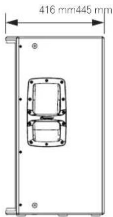
| Dimensions (W x H x D) | 445 x 750 x 416 mm |
| Weight | 29.2 kg |
| Enclosure material | 15 mm birch plywood, bass-reflex type |
| Handles | 2 (on sides) |
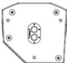
| Pole socket | 35 mm, multi-angle 0°/7° |
| Rigging points | M10 x 12 (for suspension) |
| EQ modes | FLAT, BASS+, SPEECH, WEDGE |
| Protection functions | Limiter, status monitoring, circuit/amplifier/power supply protection |
| Supplied accessories | Power cord, installation and operation manual, safety instructions |
Frequently Asked Questions - XPRS 15 PIONEER
User questions about XPRS 15 PIONEER
0 question about this device. Answer the ones you know or ask your own.
Ask a new question about this device
Download the instructions for your Pregnant in PDF format for free! Find your manual XPRS 15 - PIONEER and take your electronic device back in hand. On this page are published all the documents necessary for the use of your device. XPRS 15 by PIONEER.
USER MANUAL XPRS 15 PIONEER
The Pioneer DJ support site shown above offers FAQs, information on software and various other types of information and services to allow you to use your product in greater comfort.
Operating Instructions
Mode d'emploi
Bedienungsanleitung
How to Read This Document
Thank you for purchasing a Pioneer DJ product. To ensure you can maximize the functions of this device and use them effectively, please read this Operating Instructions and Important Safety Precautions thoroughly for correct use.
Please be sure to read in particular the Important Safety Precautions, and keep the Operating Instructions and Important Safety Precautions together with the Warranty.
For more information on installation, please read the Installation Manual.
http://pioneerproaudio.com
Main Features
2 400-W high output and high sound quality are achieved by mounting a D-class amplifier module of the professional amplifier leading company Powersoft in a wooden cabinet featuring outstanding acoustic characteristics.
The XPRS can be used not only as a stationary sound system in a stationary facility but also as sound equipment for events as it can be easily transported and set up quickly.
■ High sound quality design of wooden cabinet structure featuring outstanding acoustic characteristics
A wooden cabinet is employed to provide superior sound quality in all models.
The cabinet made of highly rigid materials features outstanding acoustic characteristics and reproduces clear sound quality ranging from a minute sound to a powerful sound.
■ Equipped with a high-efficiency and high-power class-D amplifier module
The XPRS is equipped with a D-class amplifier module realized by the technology of Powersoft and achieves a 2 400-W (at peak) high output comparable with that of a large power amplifier.
A very high power efficiency can reduce the energy required to get the same output power.
■ Advanced protective functions preventing field problems
A variety of functions such as status monitoring and limiter functions reliably protect the driver, amplifier, and power supply by using advanced DSP control. Protective circuits designed to meet the reliability requirements for professional use prevent problems in the field.
■ A variety of I/O terminals enabling flexible system connections
A mixing function is available which mixes multiple input sources and outputs them. In addition, a through output terminal is available to make it easy to connect with full-range speakers and multiple subwoofers.
■ Four EQ modes enabling a quick system setup (full-range models)
Four EQ modes of FLAT, BASS+, SPEECH, and WEDGE are available which enable selection of the optimum acoustic characteristic to suit the application by just selecting a switch.
■ Multi-angle pole socket enabling installation of a pole at two angles (full-range models)
Two angles of 0 and 7 can be selected to suit the size of the venue when installing the speakers using a pole.
Confirm All Accessories
Power cords
Installation and Operation Manual (this document)
Important Safety Precautions
The contents of the warranty for the United States and Canada are provided on the last pages of the instructions in English and French.
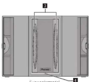
Names and Functions of Parts
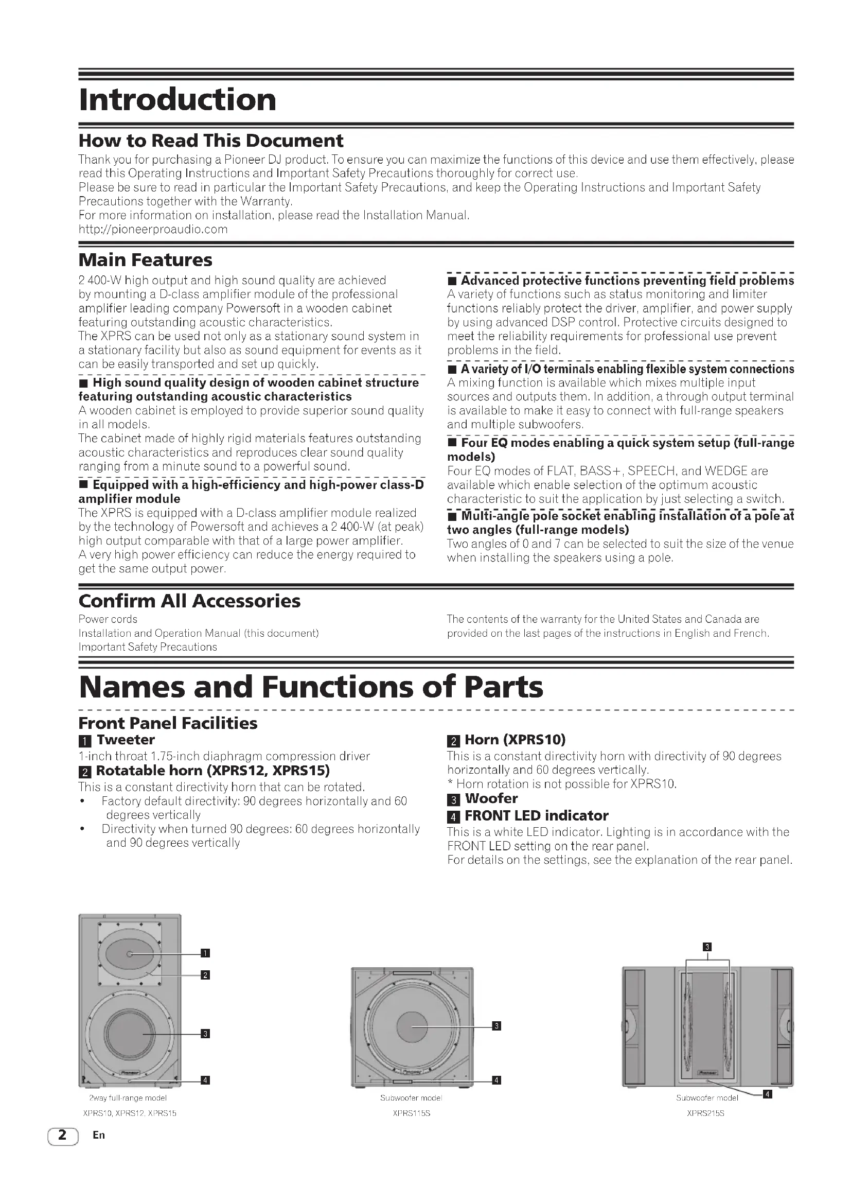
Front Panel Facilities
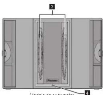
1 Tweeter
1-inch throat 1.75-inch diaphragm compression driver
2 Rotatable horn (XPRS12, XPRS15)
This is a constant directivity horn that can be rotated.
• Factory default directivity: 90 degrees horizontally and 60 degrees vertically
- Directivity when turned 90 degrees: 60 degrees horizontally and 90 degrees vertically
2 Horn (XPRS10)
This is a constant directivity horn with directivity of 90 degrees horizontally and 60 degrees vertically.
* Horn rotation is not possible for XPRS10.
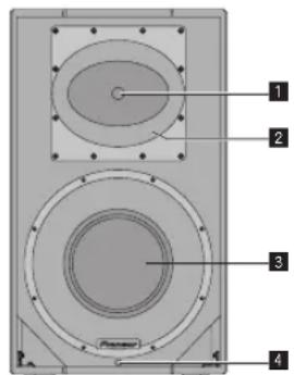
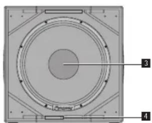
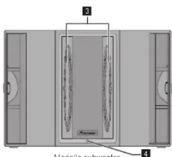
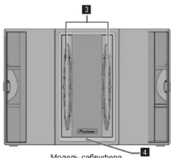
3 Woofer
4 FRONT LED indicator
This is a white LED indicator. Lighting is in accordance with the FRONT LED setting on the rear panel.
For details on the settings, see the explanation of the rear panel.
2way full-range model
XPRS10, XPRS12, XPRS15
natural_image
Technical diagram of a circular mechanical component with numbered annotations (3 and 4) pointing to internal features.Subwoofer model
XPRS115S
XPRS215S
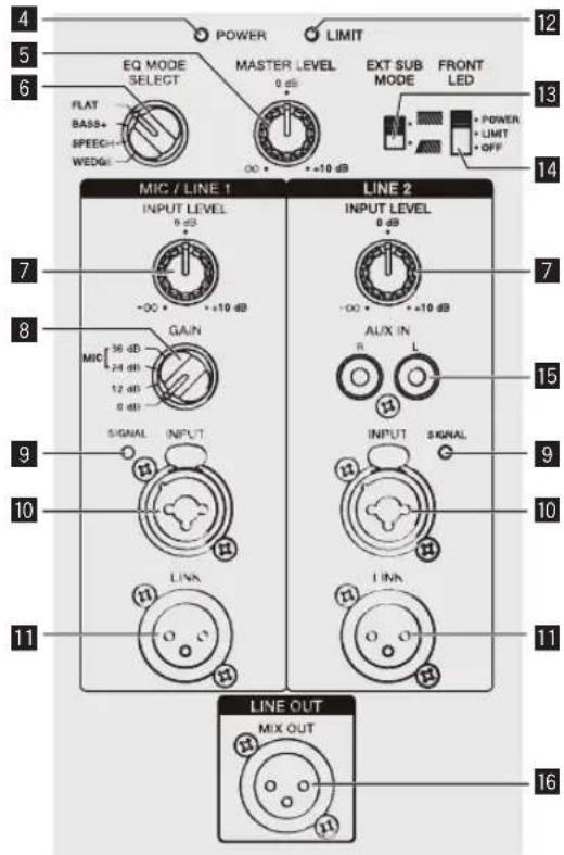
Rear Panel Facilities (Full-Range Models)

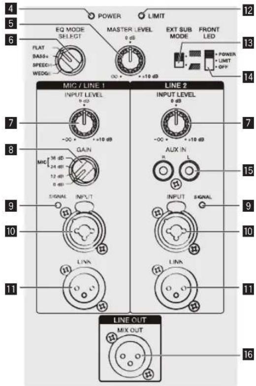
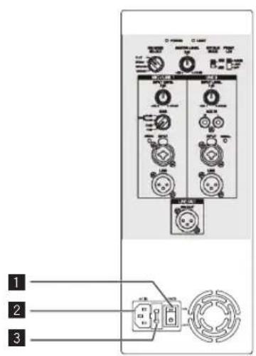
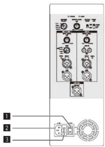
1 POWER switch
Turns this speaker's power on and off.
2 AC IN
Connect the power cord to AC IN and then to the power outlet.
3 Fuse holder
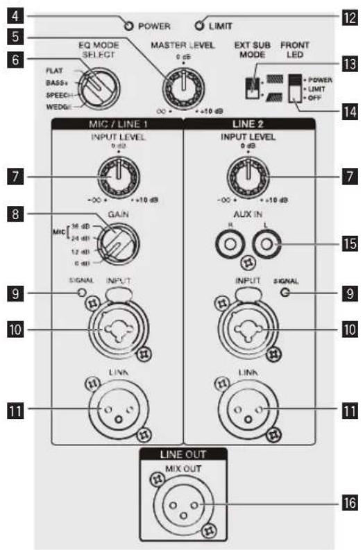
4 Power indicator
Lights in blue when the power is turned on.
5 MASTER LEVEL
Adjusts the output level.
6 EQ MODE SELECT
Switches to four EQ modes (FLAT, BASS+, SPEECH, and WEDGE). For details, see "EQ MODE Settings" on page 6.
7 INPUT LEVEL knob
Adjusts the input signal level.
8 GAIN knob (for MIC/LINE1 only)
Select the gain according to the output signal level of the device to be connected. The selected gain is added to the signal input to this unit.
• To input the signal of a line output device to this speaker, select [0 dB] or [12 dB].
• To input a low-level output signal such as that of a microphone to this unit, select [24 dB] or [36 dB].
9 SIGNAL indicator
A green indicator lights when an input signal is detected.
10 MIC/LINE1 and LINE2 INPUT
Both the XLR connector (balanced) and 1/4" TRS (balanced type PHONO) are supported. The XLR connector consists of 1 "ground," 2 "hot," and 3 "cold."
11 LINK
This is the XLR output connector (balanced). A signal input to XLR INPUT will be output directly. (A signal input to AUX IN of LINE2 will not be output.)
12 LIMIT indicator
Lights in red when the built-in limiter is activated or when the input level is too high and the sound is distorted. When that happens, lower the output level of the connected device or lower the input level or master level of this unit.
13 EXT SUB MODE
Select [ . for normal use. Select [ * ] when using a subwoofer.
14 FRONT LED
Selects the display setting of the FRONT LED indicator (white). [POWER] Lights when the power is turned on. [LIMIT] Lights when the limiter is activated. [OFF] The FRONT LED does not light.
15 AUX IN
These are the RCA input connectors (unbalanced). A stereo signal input to AUX IN is mixed to a monaural signal (not output from the LINK connector).
16 MIX OUT
This is the XLR output connector (balanced). Mixes the signal input to MIC/LINE1 and Line2 and then outputs it. A signal adjusted in MIC GAIN and INPUT LEVEL is output.
CAUTION
When the FRONT LED setting is set to [OFF] and [LIMIT], the speaker may appear the same as when the power plug is disconnected from the power outlet depending on the specification of the product, but the power is not shut off. If you wish to shut off the power to the woofer completely, you must disconnect the power plug from the power outlet. Install the speaker near a power outlet so the power plug can easily be accessed. Leaving the power plug inserted in a power outlet for a long period of time may cause fire.
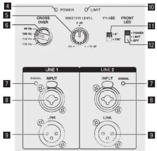
Rear Panel Facilities (Subwoofer Model)
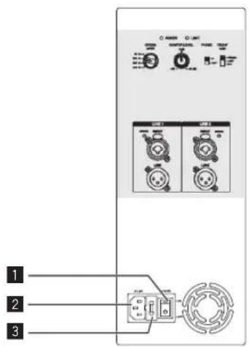

1 POWER switch
Turns this speaker's power on and off.
2 AC IN
Connect the power cord to AC IN and then to the power outlet.
3 Fuse holder
4 Power indicator
Lights in blue when the power is turned on.
5 MASTER LEVEL
Adjusts the output level.
6 CROSS OVER
Selects the cut-off frequency of the low pass filter for the subwoofer from 80 Hz, 100 Hz, 120 Hz, and 150 Hz. 100 Hz is recommended when using the subwoofer with the XPRS Series full-range speakers.
7 SIGNAL indicator
A green indicator lights when an input signal is detected.
8 LINE1 and LINE2 INPUT
Both the XLR connector (balanced) and 1/4" TRS (balanced type PHONO) are supported. The XLR connector consists of 1 "ground," 2 "hot," and 3 "cold."
9 LINK
This is the XLR output connector (balanced). A signal input to XLR INPUT will be output directly.
10 LIMIT indicator
Lights in red when the built-in limiter is activated or when the input level is too high and the sound is distorted. When that happens, lower the output level of the connected device or lower the input level or master level of this unit.
11 PHASE
Switches the polarity for the subwoofer. Select the one that improves the playback of low frequencies when using the subwoofer with other speakers.
12 FRONT LED
Selects the display setting of the FRONT LED indicator (white). [POWER] Lights when the power is turned on. [LIMIT] Lights when the limiter is activated. [OFF] The FRONT LED does not light.
CAUTION
When the FRONT LED setting is set to [OFF] and [LIMIT], the speaker may appear the same as when the power plug is disconnected from the power outlet depending on the specification of the product, but the power is not shut off. If you wish to shut off the power to the woofer completely, you must disconnect the power plug from the power outlet. Install the speaker near a power outlet so the power plug can easily be accessed. Leaving the power plug inserted in a power outlet for a long period of time may cause fire.
Installation and Connections
How to Install
The playback sound of the speaker is subtly influenced by the conditions of the listening room. Carefully consider the installation location before installing the speaker so that it can be used in the best conditions. Pioneer DJ will not be liable for any damages arising from the use of the speaker (including but not limited to loss of business opportunities), regardless of the installation method.
Use the handles on the top or the sides of the speaker when moving and installing the speaker.

CAUTION
- When standing or laying the XPRS115S, XPRS215S, take care that the casters do not slip and cause an injury.
- To promote proper cooling, please assure that sufficient space is preserved between the speakers and nearby walls or other components (minimum 30 cm or more above, behind, and to right and left sides of each speaker). Leaving insufficient space between the speaker and walls or other components may lead to rising interior temperatures, leading to malfunction or damage.
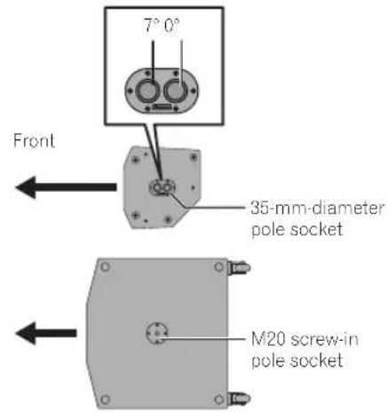
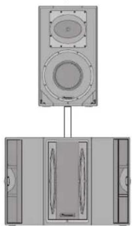
Installation Using a Speaker Pole
XPRS12/XPRS15
The full-range models of the XPRS series have a 35-mm-diameter multi-angle pole socket on the bottom surface and can be installed downward at an angle of 0° or 7° to the floor surface.
The subwoofer model of the XPRS series has an M20 screw-in pole socket on the top surface and the pole can be secured firmly.
The combinations shown in the following figures are recommended for the XPRS series. Use with a combination other than those may result in the speakers toppling over, causing damage or injury. To use a speaker pole, check the cautions on the right and perform the installation safely.
Multi-angle pole socket
Installation using a speaker pole

CAUTION
- At least two persons should together lift the speaker to install. Give sufficient consideration to safety when performing the work.
- For the speaker pole, use a 35-mm-diameter, one-side M20 screw-in speaker pole. Use a commercially-available product with a length of 900 mm or less. Pioneer DJ will not be liable for any damages (including but not limited to loss of business opportunities) arising from the use of a speaker pole other than specified.
• Install the subwoofer in a stable location and secure the speaker pole firmly. - Ensure that there is no danger of toppling.
- Cables should be taped or tied together with cable ties so as to avoid the danger of tripping on the cables and toppling the speaker.
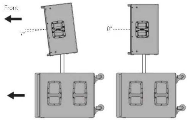
XPRS12, XPRS15
natural_image
Diagram of a speaker setup with two speakers and three speakers, showing front and side views (no text or labels)XPRS215S
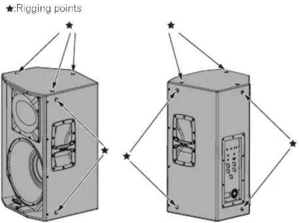
Installation Using the Rigging Points on the Speaker
- The full-range models have suspension-mounting rigging points on them. The speaker can be suspended using commercially-available eye bolts. The rigging point has an M10 screw hole (for an eye bolt with a thread length of 30 mm to 50 mm).
- When installing the speaker suspended, ask a qualified technician to perform the work.
- Remove the screws from the rigging points on the speaker and attach eye bolts. Do not use the speaker while the screws are removed. The sound will be adversely affected by air leakage.
- Be sure to use at least three rigging points to suspend the speaker. Furthermore, be sure to also implement an extra safety measure such as using a wire.
- Use brackets, wires, and a wall or ceiling strong enough to bear the weight of the speaker. Ask for commercially-available brackets at the shop where you purchased the speaker.
- Be sure to confirm the safety after installing the speaker and periodically thereafter.
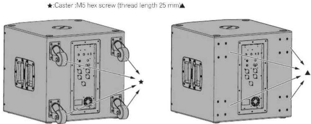
Casters of the subwoofer model
- The subwoofer model comes with casters that allow you to easily move it around.
• To use it as a fixed installation, you can remove the casters. - When using it with the casters removed, be sure to put back the caster fixing screws. If you use it with the screws removed, the sound quality will be affected by air leakage.
EQ MODE Settings
Four EQ modes (FLAT, BASS+, SPEECH, and WEDGE) are available for the full-range models. EQ MODE can be selected from four options using the [EQ MODE SELECT] switch. Select the best mode according to your preferences and the usage situation.
FLAT
Reproduces the input sound faithfully. (Factory default setting)
BASS+
This setting increases the presence of low frequencies and reproduces powerful dance music at a club, etc.
SPEECH
This setting emphasizes the voice frequencies to make it easy to listen to the voice of a lecturer, etc.
WEDGE
This setting suppresses the excessive boost in the low frequencies that occurs when the speaker is installed on the floor surface as a floor monitor.
Connections
When making or changing connections, always turn off the power and disconnect the power cord from its outlet. Also, be sure to read the operating instructions for the other components to which you are connecting these speakers. Do not connect the power cord until all other connections are completed. Use only the furnished accessory power cord.
Setup example
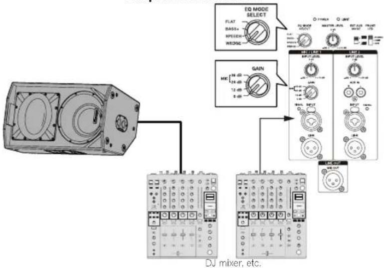
General Stereo System
Amplifier connection
flowchart
graph TD
    A["DJ mixer, etc."] --> B["DJ mixer, etc."]
    B --> C["0 dB"]
    C --> D["DJ mixer, etc."]
    D --> E["EXT SUB MODE"]
    E --> F["DJ mixer, etc."]
    F --> G["EXT SUB MODE"]
    G --> H["DJ mixer, etc."]
    H --> I["EXT SUB MODE"]
    I --> J["DJ mixer, etc."]
System with Only a Microphone Connected
It is recommended to set EQ MODE SELECT to SPEECH.
Amplifier connection
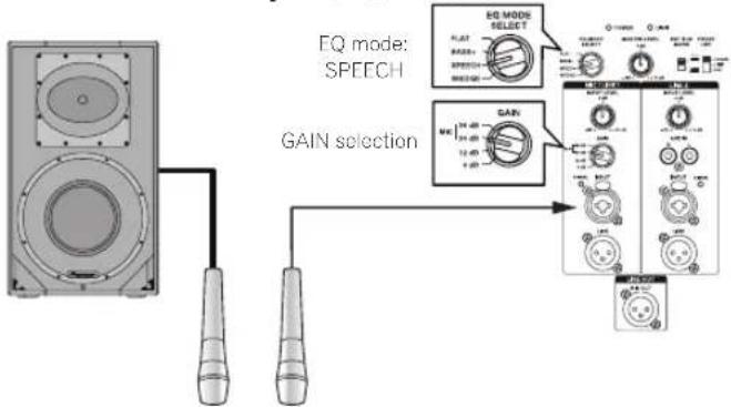
Note:
To prevent feedback howling
- Use the microphone with it's directionality out of line with the speaker's output direction. For example, use the microphone from behind the speaker, or change the direction of the microphone.
- Use the microphone with the GAIN setting and INPUT LEVEL knob set to appropriate positions.
System for Stage Monitor
Setting EQ MODE SELECT to WEDGE is recommended.
Amplifier connection
flowchart
graph TD
    A["Device"] --> B["EQ MODE SELECT"]
    A --> C["GAIN"]
    A --> D["DJ mixer, etc."]
    B --> E["Output Module 1"]
    B --> F["Output Module 2"]
    B --> G["Output Module 3"]
    C --> H["Output Module 4"]
    D --> I["Output Module 5"]
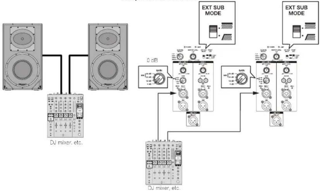
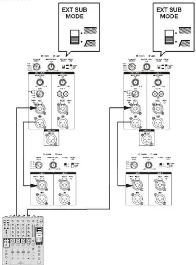
System with Subwoofer Connected
Amplifier connection
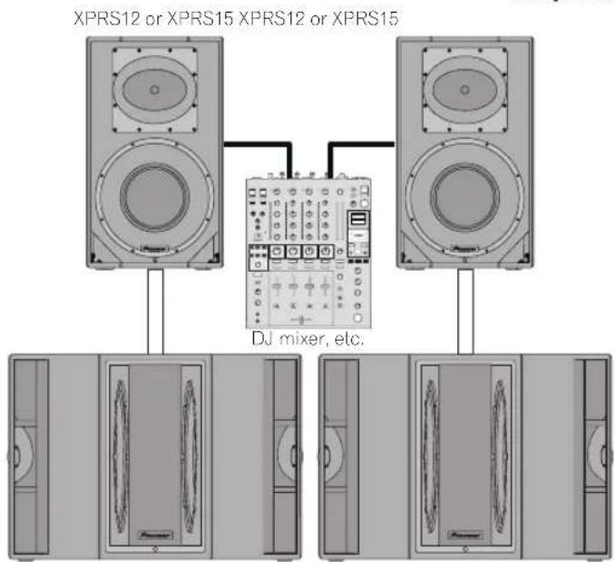
XPRS215S XPRS215S
When using the speaker with the XPRS series, it is recommended to set EXT SUB MODE of a full-range model to [ * ] and set CROSS OVER of the subwoofer model to 100 Hz.
flowchart
graph TD
    A["EXT SUB MODE"] --> B["Control Module 1"]
    A --> C["Control Module 2"]
    A --> D["Control Module 3"]
    B --> E["Switch 1: Power Supply, Control Valve, METER"]
    C --> F["Switch 2: Power Supply, Control Valve, METER"]
    D --> G["Switch 3: Power Supply, Control Valve, METER"]
    E --> H["Measurement Device"]
    F --> I["Measurement Device"]
    G --> J["Measurement Device"]
    H --> K["External Display"]
    I --> L["External Display"]
    J --> M["External Display"]
DJ mixer, etc.
System with XPRS215S Mono Mix Connected
Amplifier connection
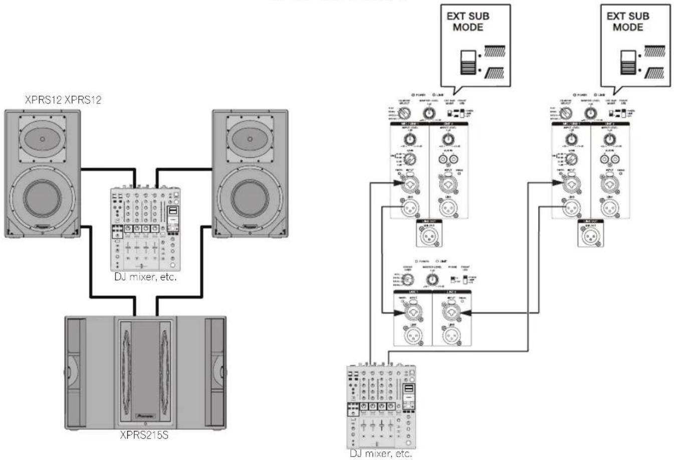
flowchart
graph TD
    A["XPRS12 XPRS12"] --> B["DJ mixer, etc."]
    C["XPRS215S"] --> B
    B --> D["DJ mixer, etc."]
    E["EXT SUB MODE"] --> F["DJ mixer, etc."]
    G["EXT SUB MODE"] --> H["DJ mixer, etc."]
Additional Information
Troubleshooting
- If you think you are experiencing a malfunction with this unit, check the following items. Also check other devices connected to the unit. If the problem persists, consult your dealer for service.
- On occasion, the unit may fail to operate properly due to static electricity or other external conditions. In this event, disconnect the power cord and wait for five seconds or more, then reconnect the power cord and check for proper operation.
| Symptom Items to Check Remedy | ||
| No power Is power cord connected properly? Connect power cord to outlet (page 6). | ||
| No sound from connected audio devices, or sound is very small. | Has connected audio device been set properly? | Set device's output selector and sound volume properly. |
| Is connection cable connected properly? Connect cables properly (page 7). | ||
| Are connectors or plugs dirty? Clean connectors and plugs before connecting. | ||
| Is sound level set properly? Turn the MASTER LEVEL knob on the rear panel of the speaker slowly to the right to increase the volume. | ||
| Is the power turned ON? Turn on the POWER switch on the rear panel of the speaker. | ||
| Sound is distorted, or the LIMIT indicator is lit. | Is the GAIN selector set appropriately? Check that the GAIN setting on the rear panel is appropriate (page 3). | |
| Is the volume set to the correct position? Turn the MASTER LEVEL or INPUT LEVEL control on the rear panel counterclockwise to reduce the volume until the LIMIT indicator turns off. | ||
| Is the output signal level of the connected equipment set appropriately? | Adjust the output level of the connected equipment. | |
| Is the output signal of the connected equipment distorted? | Check the instruction manual of the connected equipment. | |
| Howling (feedback effect) Microphone is pointed toward speaker. Change the orientation of the microphone. | ||
Specifications
| XPRS10 XPRS12 XPRS15 | |||
| Type Bi-Amplifier 2-Way Active Full Range Speaker | |||
| System characteristic | |||
| Frequency Response (-10 dB) 55 Hz to 20 kHz 50 Hz to 20 kHz 40 Hz to 20 kHz | |||
| Directional characteristic (H x V) 90° x 60° 90° x 60° (90 degree rotatable) | |||
| Maximum Sound Pressure Level (peak@1 m)* | 134 dB 135 dB 136 dB | ||
| Crossover Frequency 2.0 kHz 2.0 kHz 2.0 kHz | |||
| Amplifier | |||
| Amplifier type Class D | |||
| Amplifier output 1 200 W (LF800 W/HF400 W) peak 2 400 W | |||
| Input connectors XLR/TRS Combo x 2 (balanced) RCA x 2 (unbalanced) | |||
| Impedance 10 kΩ | |||
| Output connectors Through output XLR x 2 (balanced) Mixed output XLR x 1 (balanced) | |||
| Indicator (Front Panel Facilities) FRONT LED (Rear Panel Facilities) POWER LIMIT SIGNAL x 2 | |||
| Speaker | |||
| Woofer (LF) | 10-inch cone | 12-inch cone | 15-inch cone |
| Tweeter (HF) | 1-inch throat 1.75-inch diaphragm compression driver | ||
| Enclosure | 15 mm birch plywood bass reflex type | ||
| Handle | 1 (top) | 2 (on both sides) | |
| Pole socket | 35 mm socket (0°/7° multi-angle) | ||
| Rigging point | M10 x 12 | ||
| Power unit/other | |||
| Supported voltages | 100 V (50 Hz/60 Hz) / 110 V to 240 V (50 Hz/60 Hz) | ||
| Power consumption 162 W | 167 W | 175 W | |
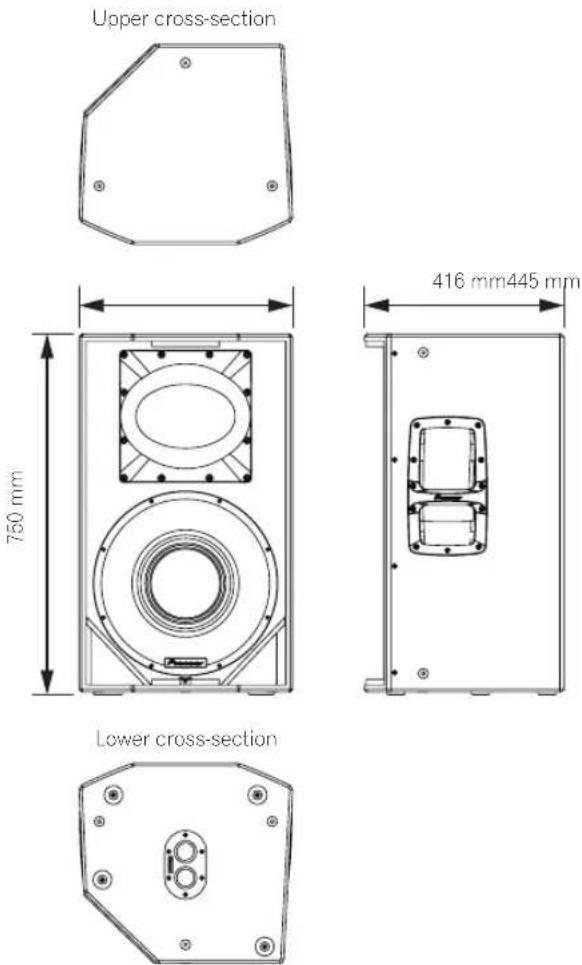
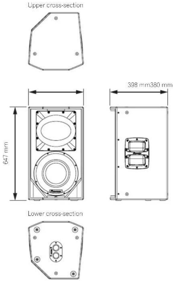
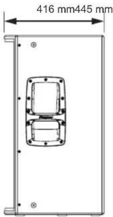
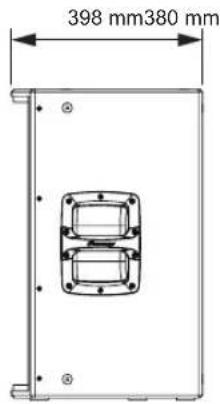
| External dimensions W x H x D | 320 mm x 520 mm x 374 mm | 380 mm x 647 mm x 398 mm | 445 mm x 750 mm x 416 mm |
| Weight | 18.9 kg | 23.1 kg | 29.2 kg |
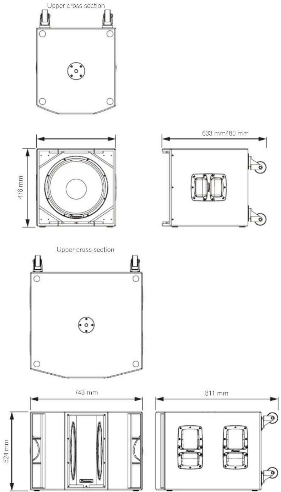
| XPRS115S | XPRS215S | |
| Type | Active Subwoofer | |
| System characteristic | ||
| Frequency Response (-10 dB) 40 | Hz to 160 Hz | Hz to 160 Hz |
| Maximum Sound Pressure Level (peak@1 m)* | 133 dB (half space) | 135 dB (half space) |
| Amplifier | ||
| Amplifier type | Class D | |
| Amplifier output | 1 200 Wpeak 2 400 W | 1 200 W (600 W x 2)peak 2 400 W |
| Input connectors | XLR/TRS Combo x 2 (balanced) | |
| Impedance | 10 kΩ | |
| Output connectors | Through output XLR x 2 (balanced) | |
| Indicator | (Front Panel Facilities) FRONT LED(Rear Panel Facilities) POWER LIMIT SIGNAL x 2 | |
| Speaker | ||
| Woofer (LF) | 15-inch cone | 15-inch cone×2 |
| Enclosure | 15 mm birch plywood bass reflex type | 15 mm birch plywood quasi band pass type |
| Handle | 2 (on both sides) | 4 (on both sides) |
| Pole socket | M20 screw socket | |
| Power unit/other | ||
| Supported voltages | 100 V (50 Hz/60 Hz) / 110 V to 240 V (50 Hz/60 Hz) | |
| Power consumption 240 W | 240 W | |
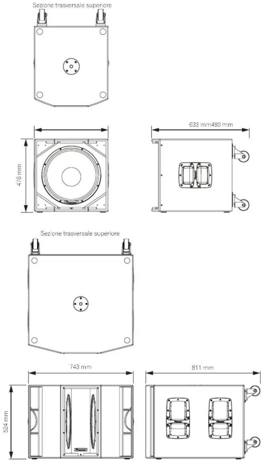
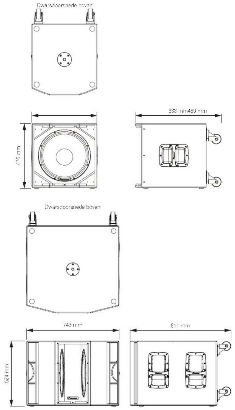
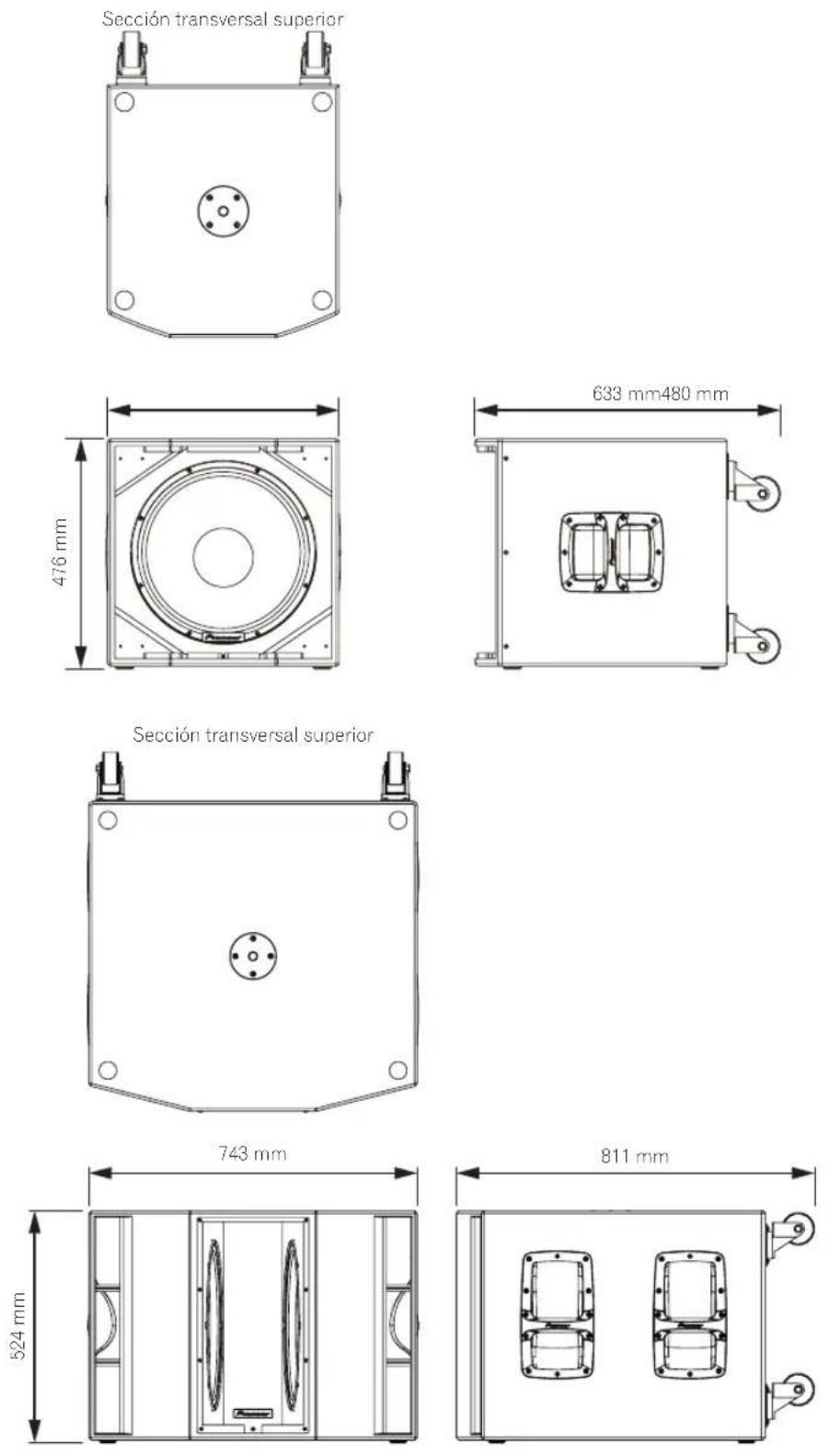
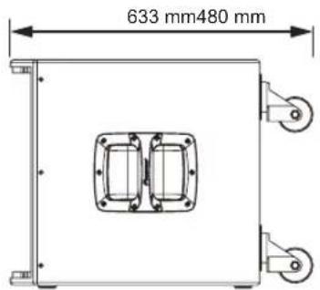
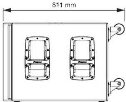
| External dimensions W x H x D | 480 mm x 476 mm x 633 mm | 743 mm x 524 mm x 811 mm |
| Weight | 30.6 kg | 55.9 kg |
* Calculated value
Specifications and design are subject to possible modification without notice, due to improvements.
Dimensions
XPRS10
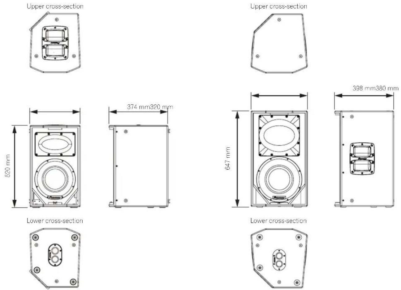
XPRS15
XPRS12
XPRS215S
AFTER-SALES SERVICE FOR Pioneer DJ PRODUCTS
Please contact the dealer or distributor from where you purchased the product for its after-sales service (including warranty conditions) or any other information. In case the necessary information is not available, please contact the Pioneer's subsidiaries (regional service headquarters) listed below:
PLEASE DO NOT SHIP YOUR PRODUCT TO THE COMPANIES at the addresses listed below for repair without advance contact, for these companies are not repair locations.
AMERICA
PIONEER ELECTRONICS (USA) INC.
P.O. BOX 1760, LONG BEACH, CA 90801-1760, U.S.A.
EUROPE
PIONEER EUROPE NV
EUROPEAN SERVICE DIVISION
HAVEN 1087, KEETBERGLAAN 1, B-9120 MELSELE, BELGIUM
ASEAN
PIONEER ELECTRONICS ASIACENTRE PTE. LTD.
SERVICE DEPARTMENT
2 JALAN KILANG BARAT, #07-01, SINGAPORE 159346
JAPAN AND OTHERS
PIONEER SERVICE NETWORK
SUMITOMO FUDOSAN NISHISHINJUKU BUILDING 6F, 4-15-3
Pioneer DJ Americas, Inc.
LIMITED WARRANTY
WARRANTY VALID ONLY IN THE U.S.A. AND CANADA
WARRANTY
Pioneer DJ Americas, Inc. (PDJA) warrants that products distributed by PDJA in the U.S.A. and Canada that fail to function properly under normal use due to a manufacturing defect when installed and operated according to the owner's manual enclosed with the unit will be repaired or replaced with a unit of comparable value, at the option of PDJA, without charge to you for parts or actual repair work. Parts supplied under this warranty may be new or rebuilt at the option of PDJA.
THIS LIMITED WARRANTY APPLIESTOTHE ORIGINAL OR ANY SUBSEQUENT OWNER OF THIS PIONEER DJ PRODUCT DURING THE WARRANTY PERIOD PROVIDED THE PRODUCT WAS PURCHASED FROM AN AUTHORIZED PIONEER DJ DISTRIBUTOR/DEALER IN THE U.S.A. OR CANADA. YOU WILL BE REQUIRED TO PROVIDE A SALES RECEIPT OR OTHERWISE VALID PROOF OF PURCHASE SHOWING THE DATE OF ORIGINAL PURCHASE OR, IF RENTED, YOUR RENTAL CONTRACT SHOWING THE PLACE AND DATE OF FIRST RENTAL. IN THE EVENT SERVICE IS REQUIRED, THE PRODUCT MUST BE DELIVERED WITHIN THE WARRANTY PERIOD, TRANSPORTATION PREPAID, ONLY FROM WITHIN THE U.S.A. AS EXPLAINED IN THIS DOCUMENT. YOU WILL BE RESPONSIBLE FOR REMOVAL AND INSTALLATION OF THE PRODUCT. PDJA WILL PAY TO RETURN THE REPAIRED OR REPLACEMENT PRODUCT TO YOU WITHIN THE U.S.A.
PRODUCT WARRANTY PERIOD
Parts
L
abo
Active Loudspeaker/Subwoofer : XPRS Series
3 Year
3 Year
The warranty period for retail customers who rent the product commences upon the date product is first put into use (a) during the rental period or (b) retail sale, whichever occurs first.
WHAT IS NOT COVERED
IF THIS PRODUCT WAS PURCHASED FROM AN UNAUTHORIZED DISTRIBUTOR, THERE ARE NO WARRANTIES, EXPRESS OR IMPLIED, INCLUDING THE IMPLIED WARRANTY OF MERCHANTABILITY AND THE IMPLIED WARRANTY OF FITNESS FOR A PARTICULAR PURPOSE AND THIS PRODUCT IS SOLD STRICTLY "AS IS" AND "WITH ALL FAULTS".
PIONEER DJ SHALL NOT BE LIABLE FOR ANY CONSEQUENTIAL AND/OR INCIDENTAL DAMAGES.
THIS WARRANTY DOES NOT APPLY IF THE PRODUCT HAS BEEN SUBJECTED TO POWER IN EXCESS OF ITS PUBLISHED POWER RATING.
THIS WARRANTY DOES NOT COVERTHE CABINET OR ANY APPEARANCE ITEM, USER ATTACHED ANTENNA, ANY DAMAGETO RECORDS OR RECORDING TAPE S OR DISCS, ANY DAMAGETO THE PRODUCT RESULTING FROM ALTERATIONS, MODIFICATIONS NOT AUTHORIZED IN WRITING BY PIONEER DJ, ACCIDENT, MISUSE OR ABUSE, DAMAGE DUE TO LIGHTNING ORTO POWERSURGES, SUBSEQUENT DAMAGE FROM LEAKING, DAMAGE FROM INOPERATIVE BATTERIES, OR THE USE OF BATTERIES NOT CONFORMING TOTHOSE SPECIFIED IN THE OWNER'S MANUAL.
THIS WARRANTY DOES NOT COVER THE COST OF PARTS OR LABOR WHICH WOULD BE OTHERWISE PROVIDED WITHOUT CHARGE UNDER THIS WARRANTY OBTAINED FROM ANY SOURCE OTHER THAN A PIONEER DJ AUTHORIZED SERVICE COMPANY OR OTHER DESIGNATED LOCATION. THIS WARRANTY DOES NOT COVER DEFECTS OR DAMAGE CAUSED BY THE USE OF UNAUTHORIZED PARTS OR LABOR OR FROM IMPROPER MAINTENANCE.
ALTERED, DEFACED, OR REMOVED SERIAL NUMBERS VOID THIS ENTIRE WARRANTY
NO OTHER WARRANTIES
PIONEER DJ LIMITS ITS OBLIGATIONS UNDER ANY IMPLIED WARRANTIES INCLUDING, BUT NOT LIMITED TO, THE IMPLIED WARRANTIES OF MERCHANTABILITY AND FITNESS FOR A PARTICULAR PURPOSE, TO A PERIOD NOT TO EXCEED THE WARRANTY PERIOD. NO WARRANTIES SHALL APPLY AFTER THE WARRANTY PERIOD. SOME STATES DO NOT ALLOW LIMITATIONS ON HOW LONG AN IMPLIED WARRANTY LASTS AND SOME STATES DO NOT ALLOW THE EXCLUSIONS OR LIMITATIONS OF INCIDENTAL OR CONSEQUENTIAL DAMAGES, SO THE ABOVE LIMITATIONS OR EXCLUSIONS MAY NOT APPLY TO YOU. THIS WARRANTY GIVES YOU SPECIFIC LEGAL RIGHTS AND YOU MAY HAVE OTHER RIGHTS WHICH MAY VARY FROM STATE TO STATE.
TO OBTAIN SERVICE
PDJA has appointed a number of Authorized Service Companies throughout the U.S.A. and Canada should your product require service. To receive warranty service you need to present your sales receipt or, if rented, your rental contract showing place and date of original owner's transaction. If shipping the unit you will need to package it carefully and send it, transportation prepaid by a traceable, insured method, to an Authorized Service Company. Package the product using adequate padding material to prevent damage in transit. The original container is ideal for this purpose. Include your name, address and telephone number where you can be reached during business hours.
On all complaints and concerns in the U.S.A. and Canada call Customer Support at 1-800-872-4159.
For hook-up and operation of your unit or to locate an
Authorized Service Company, please call or write:
CUSTOMER SUPPORT
PIONEER ELECTRONICS (USA) INC.
P.O. BOX 1720
LONG BEACH, CALIFORNIA 90801
1-800-872-4159
http://www.pioneerelectronics.com
DISPUTE RESOLUTION
Following our response to any initial request to Customer Support, should a dispute arise between you and Pioneer DJ, Pioneer DJ makes available its Complaint Resolution Program to resolve the dispute. The Complaint Resolution Program is available to you without charge. You are required to use the Complaint Resolution Program before you exercise any rights under, or seek any remedies, created by Title I of the Magnuson-Moss Warranty-Federal Trade Commission Improvement Act, 15 U.S.C. 2301 et seq.
To use the Complaint Resolution Program call 1-800-872-4159 and explain to the customer service representative the problem you are experiencing, steps you have taken to have the product repaired during the warranty period and the name of the authorized Distributor/Dealer from whom the Pioneer DJ product was purchased. After the complaint has been explained to the representative, a resolution number will be issued. Within 40 days of receiving your complaint, Pioneer DJ will investigate the dispute and will either: (1) respond to your complaint in writing informing you what action Pioneer DJ will take, and in what time period, to resolve the dispute; or (2) respond to your complaint in writing informing you why it will not take any action.
RECORD THE PLACE AND DATE OF PURCHASE FOR FUTURE REFERENCE
Model No.
Serial No.
Purchase Date
Purchased From
KEEP THIS INFORMATION AND YOUR SALES RECEIPT IN A SAFE PLACE
UCP0516
Introduction
natural_image
Technical diagram of a circular mechanical component with labeled parts (3 and 4), no readable text or symbols beyond labelsnatural_image
Diagram of a room layout with labeled components, showing front and side views (no readable text or symbols)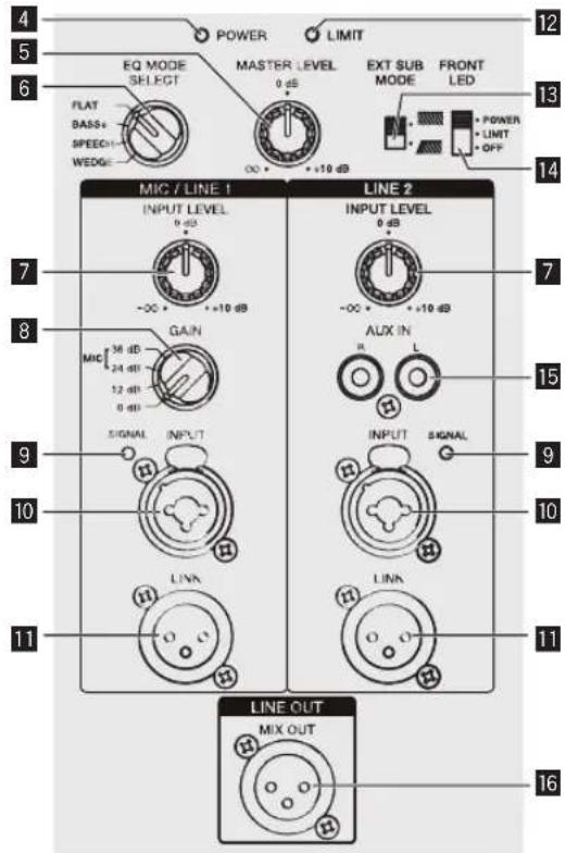
Installation et raccordements
Comment installer
natural_image
Diagram of a speaker with two circular components and three side panels, no text or symbols presentXPRS215S
natural_image
Simple geometric shape with four marked points (no text or symbols)
natural_image
Technical line drawing of a hexagonal mechanical component with central oval and four corner holes (no text or symbols)XPRS12
XPRS215S

Pioneer Dj
Pioneer DJ Americas, Inc.
GARANTIE LIMITÉE
GARANTIE VALABLE UNIQUEMENT AUX ÉTATS-UNIS ET AU CANADA
GARANTIE
PIONEER ELECTRONICS (USA) INC.
P.O. BOX 1720
LONG BEACH, CALIFORNIA 90801
1-800-872-4159
http://www.pioneerelectronics.com
RÉSOLUTION DES LITIGES
natural_image
Technical diagram of a circular mechanical component with labeled parts (3 and 4), no readable text or symbols beyond labelsSubwoofermodell
XPRS115S

XPRS215S

1 POWER-Schalter
1 POWER-Schalter
natural_image
Diagram of a speaker setup with two speakers and three front panels (no text or labels)XPRS215S
natural_image
Technical line drawing of two mechanical or electronic device components with no visible text or symbolsnatural_image
Technical line drawing of a mechanical device with mounting holes and control panel (no text or symbols)natural_image
Technical diagram of a mechanical device with labeled components and directional arrows (no text or symbols)natural_image
Technical diagram of a circular mechanical component with labeled parts (3 and 4), no readable text or symbols beyond labelsModello subwoofer
XPRS115S
XPRS215S
Componenti del pannello posteriore (modelli a gamma completa)

natural_image
Diagram of a speaker tower with two speakers and three front panels (no text or labels)XPRS215S
natural_image
Technical line drawing of two mechanical device cases with mounting holes and control panels, no text or symbols presentnatural_image
Simple geometric shape with four marked points (no text or symbols)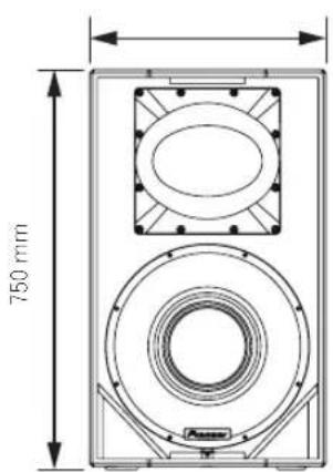
natural_image
Technical line drawing of a hexagonal mechanical component with central oval and four corner holes (no text or symbols)natural_image
Simple geometric shape with four marked points on its edges (no text or symbols)
natural_image
Technical line drawing of a mechanical housing or bracket with mounting holes and central oval feature (no text or symbols)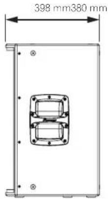
XPRS215S
Italiano
Inleiding
Opmerkingen over dit document
Installation and Operation Manual (this document)
natural_image
Technical diagram of a circular mechanical component with labeled parts (3 and 4), no readable text or symbols beyond labelsSubwoofermodel
XPRS115S
XPRS215S

1 POWER-schakelaar
natural_image
Diagram of a speaker setup with two speakers and a central display unit (no text or labels)XPRS215S
flowchart
graph TD
    A["EXT SUB MODE"] --> B["Control Module 1"]
    A --> C["Control Module 2"]
    A --> D["Control Module 3"]
    B --> E["Switch 1: Power Supply"]
    B --> F["Switch 2: Power Supply"]
    C --> G["Switch 3: Power Supply"]
    C --> H["Switch 4: Power Supply"]
    D --> I["Switch 5: Power Supply"]
    D --> J["Switch 6: Power Supply"]
    E --> K["Measurement Device"]
    F --> L["Measurement Device"]
    G --> M["Measurement Device"]
    H --> N["Measurement Device"]
    I --> O["Measurement Device"]
    J --> P["Measurement Device"]
DJ-mengpaneel, enz.
natural_image
Simple geometric shape with four marked points (no text or symbols)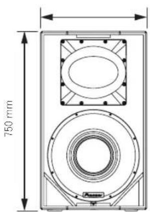
natural_image
Technical line drawing of a mechanical component with mounting holes and central oval feature (no text or symbols)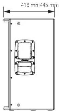
XPRS12
XPRS215S
Introducción
natural_image
Technical diagram of a circular mechanical component with labeled parts (3 and 4), no readable text or symbols beyond labels
1 Interruptor POWER
natural_image
Technical line drawing of two mechanical device cases with mounting holes and ventilation grilles, no text or symbols presentnatural_image
Simple geometric shape with four marked points on its edges (no text or symbols)

natural_image
Technical line drawing of a hexagonal mechanical component with central oval and four corner holes (no text or symbols)natural_image
Simple geometric shape with four marked points on its edges (no text or symbols)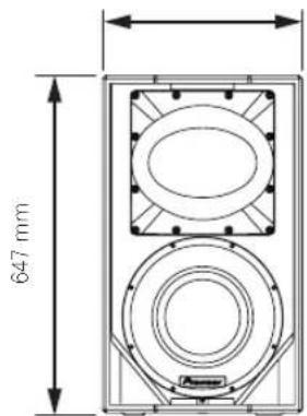
natural_image
Technical line drawing of a mechanical component with mounting holes and central bore (no text or symbols)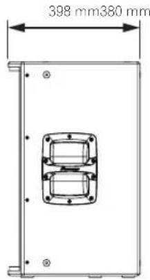
XPRS215S
Español
Introdução
natural_image
Technical diagram of a circular mechanical component with labeled parts (3 and 4), no readable text or symbols beyond labelsModelo de subwoofer
XPRS115S
XPRS215S
1 Interruptor POWER
Adjusts the output level.
6 EQ MODE SELECT

1 Interruptor POWER
natural_image
Diagram of a speaker setup with two speakers and three front panels (no text or labels)XPRS215S
natural_image
Technical line drawing of two mechanical device cases with mounting holes and control panels, no text or symbols presentRodas do modelo de subwoofer
natural_image
Simple geometric shape with four marked points (no text or symbols)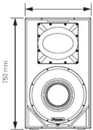
Corte transversal inferior
natural_image
Technical line drawing of a hexagonal mechanical component with mounting holes and central oval feature (no text or symbols)
XPRS12
XPRS115S
XPRS215S

Portugues
Введение
natural_image
Technical diagram of a circular mechanical component with labeled parts (3 and 4), no readable text or symbols beyond labelsМодель сабвуфера
XPRS115S
natural_image
Diagram of a speaker setup with two speakers and a central speaker (no text or labels)XPRS215S
natural_image
Technical line drawing of a speaker or audio device with 520 mm height dimension标注 (no text or symbols beyond measurement)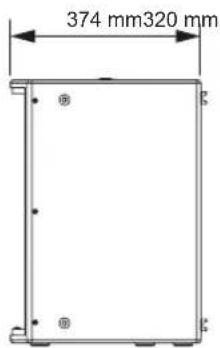
natural_image
Simple geometric shape with four corner dots, no text or symbols present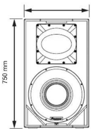
natural_image
Technical line drawing of a mechanical component with mounting holes and a central oval feature (no text or symbols)natural_image
Simple geometric shape with four corner dots, no text or symbols present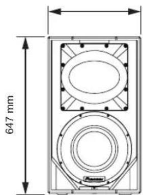
natural_image
Technical line drawing of a mechanical housing or enclosure with bolt holes and central mounting hole (no text or symbols)XPRS115S
natural_image
Technical line drawing of a rectangular mechanical component with mounting holes and a central circular feature (no text or symbols)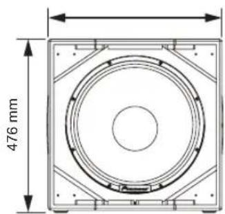
XPRS215S
natural_image
Simple line drawing of a rectangular frame with four corner holes and a central circular hole (no text or symbols)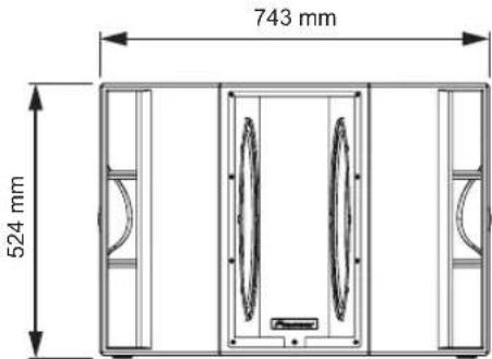
РУССКИЙ
はじめに
本書の見方
natural_image
Diagram of a room layout with doors, doors, and a central door (no text or symbols)サブウーファーモデル
XPRS215S
本体背面部(フルレンジモデル)
1 POWER スイッチ
本機の電源をオン/オフします。
2 AC IN
natural_image
Diagram of a speaker setup with two speakers and a central speaker (no text or labels)XPRS215S
pioneerdj.com/support/purpose/repair/
© 2017 Pioneer DJ Corporation. All rights reserved.
Pioneer DJ Corporation
6F, Yokohama i-Mark Place, 4-4-5 Minatomirai, Nishi-ku, Yokohama, Kanagawa 220-0012 JAPAN
Pioneer DJ 株式会社
Pioneer DJ Europe Limited
Anteros Building, Odyssey Business Park, West End Road, South Ruislip, Middlesex, HA4 6QQ, U.K. TEL: +44-203-7617-220
Pioneer DJ Americas, Inc.
2050 W. 190th Street, Suite 109, Torrance, CA 90504, U.S.A. TEL: +1 (424) 488-0480
PIONEER ELECTRONICS ASIACENTRE PTE. LTD.
2 Jalan Kilang Barat, #07-01, Singapore 159346 TEL: +65-6378-7888
PIONEER ELECTRONICS AUSTRALIA PTY. LTD.
5 Arco Lane, Heatherton, Victoria, 3202, Australia, TEL: +61-3-9586-6300
PIONEER ELECTRONICS (THAILAND) CO., LTD.
17th Fl., KPN Tower, 719 Rama 9 Road, Bangkapi, Huaykwang, Bangkok 10310 TEL: +66-2-717-0777
PIONEER TECHNOLOGY (MALAYSIA) SDN. BHD
16th Floor, Menara Uni. Asia 1008 Jalan Sultan Ismail 50250 Kuala Lumpur TEL: +60-3-2697-2920
先鋒股份有限公司
PIONEER INDIA ELECTRONICS PRIVATE LTD.
216, Second Floor, Time Tower, M.G. Road, Sector 28, Gurgaon 122001, Haryana, India TEL: +91-124-463-6100
PDJ 001 all
JIS C 61000-3-2 適合品
Сделано в Китае
Printed in China/Imprimé en Chine