
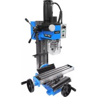
GMD 400 - Milling machine Güde - Free user manual and instructions
Find the device manual for free GMD 400 Güde in PDF.
| Product Type | Mini metal lathe (milling machine) |
| Brand | Güde |
| Model | GMD 400 |
| Weight | 35 kg |
| Power supply | 230 V ~ 50 Hz |
| Motor power | 370 W |
| Speed ranges | 0-1100 min⁻¹ (slow), 0-2500 min⁻¹ (fast) |
| Three-jaw chuck | Bore 15 mm, concentricity 0.01 mm |
| Working spindle | MK3 |
| Tailstock spindle | MK2 |
| Lathe tool clamping | 8 x 8 mm |
| Maximum capacity | Workpiece length: 300 mm, max Ø: 180 mm, center height: 90 mm |
| Spindle bore | Ø 20 mm |
| Main functions | Longitudinal turning, cross turning, taper turning, threading, drilling, boring |
| Safety | Emergency stop, protective cover with safety switch |
| Maintenance | Cleaning after each use, regular lubrication of slides and screws |
| Wear parts | Drive belt, carbon brushes, fuse, clamping jaws |
| Warranty | 12 months (industrial use), 24 months (end consumer) |
| Package contents | Machine, 9 spare gear wheels, keys, oil can, chuck, jaws, center point |
Frequently Asked Questions - GMD 400 Güde
User questions about GMD 400 Güde
0 question about this device. Answer the ones you know or ask your own.
Ask a new question about this device
Download the instructions for your Milling machine in PDF format for free! Find your manual GMD 400 - Güde and take your electronic device back in hand. On this page are published all the documents necessary for the use of your device. GMD 400 by Güde.
USER MANUAL GMD 400 Güde
A.V. 2 For reprints, even partial, permission required. Technical changes reserved. Similar pictures!
| EN EN | Thank you for buying the mini lathe Gude GMD 400 and for your trust in our products. !!! Please read the operating manual carefully before starting the machine !!! | ||
| EN | Any technical questions? Complaints? In need of spare parts or operating manual? On our web pages www.quede.com we will help you fast and without needless bureaucracy. Please help us so we can help you. To identify your machine in case of any claim, we need to know serial number, product number and year of production. You can find all these data on the type label. To have them handy please write them down in here: Serial number: Product number: Year of production: | ||
| Tel.: +49 (0) 79 04 / 700-360 | Tel.: +49 (0) 79 04 / 700-360 | Tel.: +49 (0) 79 04 / 700-360 | |
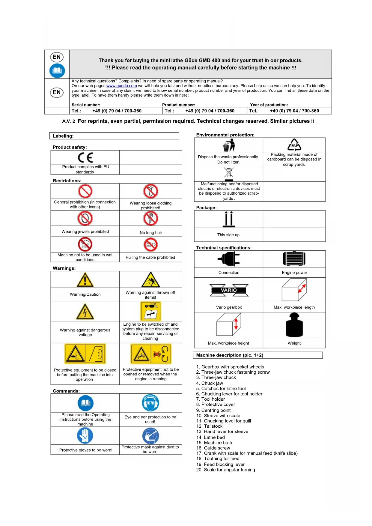
| Labeling: | |
| Product safety: | |
| CE | |
| Product complies with EU standards | |
| General prohibition (in connection with other icons) | Wearing loose clothing prohibited! |
| Wearing jewels prohibited | No long hair |
| Machine not to be used in wet conditions | Pulling the cable prohibited |
| Warning: | |
| Warning/Caution | Warning against thrown-off items! |
| Warning against dangerous voltage | Engine to be switched off and system plug to be disconnected before any repair, servicing or cleaning |
| Protective equipment to be closed before putting the machine into operation | Protective equipment not to be opened or removed when the engine is running |
| Please read the Operating Instructions before using the machine | Eye and ear protection to be used! |
| Protective gloves to be worn! | Protective mask against dust to be worn! |
| Environmental protection: | |
| PAP | |
| Dispose the waste professionally. Do not litter. | Packing material made of cardboard can be disposed in scrap-yards. |
| Malfunctioning and/or disposed electric or electronic devices must be disposed to authorized scrap-yards. | |
| Package: | |
| This side up | |
| Technical specifications: | |
| Connection | Engine power |
| VARIO | |
| Vario gearbox | Max. workpiece length |
| Max. workpiece height | Weight |
Machine description (pic. 1+2)
- Gearbox with sprocket wheels
- Three-jaw chuck fastening screw
- Three-jaw chuck
- Chuck jaw
5.Catches for lathe tool - Chucking lever for tool holder
- Tool holder
- Protective cover
- Centring point
- Sleeve with scale
- Chucking level for quill
- Tailstock
- Hand lever for sleeve
- Lathe bed
- Machine bath
- Guide screw
- Crank with scale for manual feed (knife slide)
- Toothing for feed
- Feed blocking lever
-
Scale for angular turning
-
Crank with scale for transverse feed (surfacing slide)
- Surfacing slide
- Knife slide
- Bed slide
- Hand wheel for sliding traverse
- Safety switch (Not-Aus)
- Turning direction selector
- Speed controller
- Rear protective wall against spraying
- Engine housing
- Switch protective cover
- Fast / slow speed selector
- Power cord
- Feed direction lever
- Headstock
- Three-jaw chuck protective cover
- Sprocket wheels
- Oil bottle
- Chuck jaws
- Allen wrench
- Jaw chuck wrench
- Fork wrench
Supply includes
- 9 sprocket (exchangeable) gear wheels
- Fork wrench
- Hexagonal wrench
Oil bottle - Centring point
Three-jaw chuck
Exchangeable jaws
Machine
For turning and cutting of threads of structural steel, nonferrous metals, plastic material or wood, grooved guide with optional adjustment, drive transmission using stepped pulleys and sprocket wheels (feed screw), right/left running, electrical switching, automatic feed mechanism, continuous speed control.
Warranty
A warranty period of 12 months applies to commercial use and 24 months apply to private use and commences on the day of purchase of the device.
Warranty applies exclusively to failures due to defective material or workmanship. An original sale slip with indication of date of sale must be presented in case of claiming for the warranty rights.
Warranty does not cover unprofessional use such as device overload, violent use, damage caused by third party or foreign materials, failure to comply with operations and assembly manual, and normal wear and tear.
Technical specifications
| Engine wiring: 230V~50Hz | |
| P1 engine power: 370 W | |
| Max. workpiece length: 300 mm | |
| Max. workpiece height: 180 mm | |
| Point height: 90 mm | |
| Spindle boring-Ø: 20 mm | |
| Max. workpiece Ø – over bed: 180 mm | |
| Work spindle: MK3 | |
| Tailstock spindle: MK2 | |
| Jaw chuck boring: 15 mm | |
| Centred running accuracy: 0.01 mm | |
| Speed, level 1: 0-1,100 per min | -1 |
| Speed, level 2: 0-2,500 per min | -1 |
| Lathe tool mounting: | 8x8 mm |
| Weight: | 35 kg |
General safety instructions
Please read carefully the safety regulations below and the Operating Instructions before using the machine. Before the machine is used by other persons, they must be familiarised with these Operating Instructions. Keep the Instructions for future reference!
Package: The machine is in a package for purposes of protection against damage during transport. The packages are raw materials subject to recycling or returning back to circulation.
Please read carefully this manual and follow the instructions included. Use the manual to get acquainted with the machine, learn how to use it properly and familiarise with the safety instructions. Keep the safety instructions for future reference.
Unplug the machine before any work on it.
Use the machine in accordance with the given purpose of use.
Safety in the place of work is your responsibility.
Work under adequate light conditions only.
- Never leave the machine unattended.
- Keep the machine in a safe place after finishing your work.
- Never expose the machine to rain and moist or wet conditions.
- Protect the machine against moisture and rain.
- Do not switch the machine on when turned or, to be more specific, not in the working position.
- Keep the machine in a dry place inaccessible by children when not being used.
- All machine parts must be regularly inspected for any sign of damage or aging. The machine must not be used when not in a perfect state.
Original spare parts to be used for servicing.
- Repairs may only be executed by a professional electrician.
Before putting the machine into operation and after any impact, check the machine for any sign of wear or damage and have any repair executed.
- Never use any spare part or accessories not specified or recommended by the manufacturer.
Make sure no other items cause short-circuit on the machine contacts.
Before wiring, make sure the details on the type label correspond to the system details.
The machine is no toy for children! Children are not able to estimate the machine-related risk. Children must not use the machine in any case.
- Persons who are not able to operate the machine due to their physical, sensory or mental skills or due to inexperience or absence of knowledge must not use the machine.
If there is any sign of visible damage to the machine, it must not be put into operation.
- Serious risks may arise as a result of unauthorised repairs.
The same regulations apply to accessories.
Güde GmbH & Co. KG will not assume any liability for damage caused as a result of the following:
Machine damage by mechanical influences and overvoltage.
Changes to the machine
Use for purposes other than those specified in the Operating Instructions.
It is necessary to follow all safety instructions to prevent injuries and damage.
Machine-specific safety instructions
- Safety shoes, eye and ear protection to be used AT ALL TIMES.
- Do not wear any loose-fitting clothes (ties, jewels, etc.). Long hair should be tied.
- Make sure your hands can move freely when operating the machine so that working is safe.
- Unplug the machine before any work on it.
- Never check the machine or take any measure in respect of the machine until the lathe spindle is fully stopped.
- Speed may only be changed when the lathe spindle is fully stopped.
- Make sure the surface is able to withstand the machine weight.
- At all times, close the protective covers before switching the machine on.
Use as designated
The lathe can be used both for outdoor and indoor turning work, face turning, thread turning and a broad range of various activities such as boring, reaming and cutting of threads. The lathe can be used in precision mechanics and do-it-yourself work, guaranteeing good results.
Disposal
Disposal instructions are illustrated in the form of pictograms on the device or packaging. Description of the pictograms is given in "Identification" chapter.
Disposal of transport packaging
Packaging protects the device against damage during transport. Packaging materials are usually selected according to their effect on environment and disposal methods and can therefore be recycled.
Returning of the packaging back to circulation saves resources and costs for packaging disposal.
Parts of the packaging (e.g. foil, styropor) may be dangerous for children. Risk of suffocation!
Keep these parts of the packaging out of reach of children and dispose as soon as possible.
Operator requirements
The operator should carefully read the Operating Instructions before using the machine.
Residual risks and protective measures
Even if this electric machine is operated in accordance with the applicable rules and regulations, some residual risks still exist.
The following risks may arise in connection with the design of this electric machine:
- Damage to lungs if an appropriate mask for the protection against dust is not worn.
- Hearing damage if appropriate hearing protection is not used.
- Damage to health arising from vibration affecting hands and shoulders if the machine has been used for a long time or is not properly maintained.
- Direct electric contact
A defective cable or plug may lead to electric shock dangerous to life.
At all times, have any defective cable or plug replaced by an expert. Only a machine connected to a safety switch against stray current to be used.
- Indirect electric contact
Injury by live parts in case of exposed electric or defective structural parts.
System plug to be always disconnected before any servicing. Work on RCD switches only.
- Inappropriate local lighting, inadequate lighting represent a high safety risk.
At all times, provide appropriate and adequate lighting for your work with the machine.
Qualification
There is no need for any special qualification except for detailed training by qualified person.
Minimum age
Operate the machine can only people 16+ years old. Exception is made when using by youths during the occupational training to achieve exact skills under the supervision of a trainer.
Training
There is a corresponding course needed only to operate this machine. No special training is necessary.
Putting the machine into operation
- Before putting the machine into operation, check thoroughly if the electrical equipment installation is appropriate and if the connections on connection spots are tight. Lines/cables could get loose during transport, resulting in a risk of injury when connected to the power supply.
- The guiding surfaces of the machine bed and all exposed parts are treated with anti-corrosive agents for transport purposes. The anti-corrosive agents can be removed by paraffin or petrol for washing purposes. Then, dry out the machine bed surfaces and lubricate the guide with oil for the bed guiding surfaces.
- Check all controls if their controllability is smooth and if they can be moved smoothly backlash free. If the guides are difficult to use, get stuck or their backlash is too big, they must be adjusted with the adjustment mouldings and pressure pins.
- All controls must be checked for continuous controllability and slide and transverse guiding of bed slides, surfacing slides for continuous movement without any backlash. If guiding was difficult, got stuck or had a too big backlash, it is necessary to make an adjustment using the adjustment mouldings and pressure pins.
- Before putting the machine into operation, check thoroughly if the electrical equipment installation is appropriate and if the connections on connection spots are tight.
- All the safety equipment and covers must be fitted before the machine is put into operation.
- To put the machine into operation for the first time, set the lowest spindle speed and run the machine without any load for at least 10 minutes. Watch the bearings, etc. if not getting abnormally hot and follow the function process, noise, etc. If no anomaly is found, the spindle speed can gradually be increased to the maximum level.
- All interfaces, lubrication holes and surfaces on the machine to be lubricated should be treated with lubrication oil.
Installation / Change of chuck jaws (pic. 3-10/pos.4)
The chuck jaws (4) are numbered 1 to 3 and must be fitted in the chuck jaw guiding based on the order (A) in the three-jaw chuck (3).
- First, insert the jaw chuck key (41) in one of the fastening screws of the three-jaw chuck (2) and loosen the chuck jaw (4) by turning the jaw chuck key (41) to the left until the chuck jaw (26) can be released (picture 3).
- Choose the chuck jaws to be installed (see Inner and outer grade of chuck jaws) and sort them by their numbering (a numerical code starting with 1, 2 or 3 is imprinted on every chuck jaw) (pic. 4-7).
-
Put the chuck jaw 1 to one of the chuck jaw guiding (A) and press it towards the centre of the three-jaw chuck (3).
-
Now turn the jaw chuck key (41) to the left until the chuck jaw 1 slips a little bit towards the centre of the three-jaw chuck (3) (picture 8).
- Now fit in chuck jaws 2 and 3 clockwise to the other two chuck jaw guidings (A).
- Press all 3 chuck jaws (4) to each other and clamp the three-jaw chuck (3) by turning the jaw chuck key (41) to the right - pictures 17 - 19.
Inside the three-jaw chuck there is a thread interfering with the notches on the back of the chuck jaws (4), by which they are clamped together (picture 9).
- Check if the clamping of the chuck jaws (4) is centred by turning the chuck jaws (4) fully to each other using the jaw chuck key (4). If not all chuck jaws (4) fit tight to the centre, they must be fitted again (picture 10).
Inner and outer grade of chuck jaws (picture 4-7/pos.4)
Workpieces with a diameter of up to app. 70~mm are clamped on their outside diameter (picture 7). Workpieces with an outside diameter of 1.5 - 30mm can be clamped with outwardly graded chuck jaws (a) (picture 5).
Workpieces with boring of at least 25mm can be clamped using outwardly graded chuck jaws (a) in boring (picture 6). Workpieces with a diameter of up to app. 70~mm can be clamped if outwardly graded chuck jaws (a) are changed for inwardly graded chuck jaws (b).
Caution:
Workpieces must be clamped in a sufficient depth in the three-jaw chuck (3). Take the jaw chuck key (41) out. Make sure the workpiece is clamped firmly.
Caution:
Make sure the outer jaws are still held by the spiral thread and are not screwed out too much!
Lathe tool clamping (pic. 11 - 12)
The lathe tool (B) is clamped by at least two clamping screws (5) in the tool holder (7). Clamp the lathe tool (B) as short as possible so that the lever (D) path is also as short as possible. Make sure the adjustment height is correct. The height position of the lathe tool (B) is achieved by putting variously thick flat sheets (C) underneath. The height position on the centre of the workpiece is checked based on the centring point (9) on the tailstock (12). The tool holder (7) can be turned by loosening the clamp lever (6) and adjusted to any other working position. Up to 4 lathe tools (B) can be clamped in the tool holder (7) at the same time. The lathe tools can be switched by turning the tool holder (7).
Caution:
The lathe tool (B) must be clamped with its axis vertically to the workpiece axis. If clamped sideways, the lathe tool (B) can be drawn in the workpiece.
Feed direction selection (pic. 13)
The guide screw (16) turning direction can be selected on the feed direction lever (34) on the back of the machine.
Pos. 1 Up: Left feed direction
Pos. 2 Middle: Feed direction off
Pos. 3 Down: Right feed direction
Feed pace, change of sprocket wheels (pic. 14-19)
To achieve various feed paces, the appropriate sprocket wheels must be chosen.
- Loosen the clamping screws (a) on the sprocket wheel box (1) and remove it (pic. 14).
- Loosen the clamping screws (d) of the shafts of the gear wheels and remove the sprocket wheels (c) from the shafts (picture 15). Loosen the clamping nuts of the balancing holder of the gear wheels (picture 16/pos.d).
- Choose the necessary sprocket wheels as shown in pictures 17 - 19. The table (picture 19) shows the necessary number of teeth (F) of the sprocket wheels for the appropriate feed in mm for one turning (E).
-
Fit the gear wheels to the appropriate shafts of the gear wheels and secure them using the clamping screws (picture 15/pos. b).
-
If gear wheels A, B and D are only needed for the necessary transmission, a clamping sleeve (E) shown in picture 18 must be fitted on the shaft III before the gear wheel.
- Adjust the balancing holder of the gear wheel and the shaft of the gear wheels in a way the gear wheels can be moved with light backlash. Now tighten the clamping nuts of the balancing holder of the gear wheels (d) (picture 16).
- Important: To switch the machine on, the cover of the box of the sprocket wheels (picture 14 / pos. 1) must be fitted.
Tailstock adjusting (pic. 1 and 20)
The tailstock (12) can be moved in the lathe bed (14) back and forth.
- For that purpose, loosen the tailstock clamping nut (43, key 42) and move the tailstock to the required position.
- Then, tighten the tailstock clamping nut properly (43, key 42).
Sleeve installation/removal/adjusting (pic. 12-21)
The sleeve (10) holds the centring point (9). It is used to clamp and check long workpieces. The sleeve (10) can be adjusted back and forth using the hand crank (13). The sleeve (10) is clamped or locked in the required position using the clamp lever (11). The rear side of the centring point (9) is conical and is held by locking in the sleeve (10). To remove the centring point (9), loosen the chucking lever (11) and use the hand crank (13) to adjust the sleeve (10) fully to the back. By this, the centring point (9) is pushed out of its clamping and can be taken out. To use it, insert the centring point (9) in the sleeve (10). When chucked, the workpiece is automatically clamped in the sleeve (10).
Instead of the centring point (9), a bore in the appropriate cone can also be inserted in the sleeve (10) for example as preparation/roughening for inner turning. There is a scale on the sleeve (10) showing how deep it is being bored to the workpiece.
Three-jaw chuck protective cover (pic. 2 / pos.36)
The three-jaw chuck protective cover (36) is used for the protection of the user. It must always be folded down when operating the machine. When the protective cover (36) is folded up, the machine cannot be switched on, as the safety switch (picture 2 / pos. 31) in the back is not controlled.
Cranks for transverse and manual run (pic. 1 / pos. 21, resp. 17)
When turning, the lathe tool is guided along the workpiece using cranks for transverse and manual running.
On both cranks there are indexing wheels with a scale that are adjusted to 0 when the lathe tool touches the workpiece. By this, the depth of turnings removal can be measured.
To adjust the indexing wheels with a scale to 0, loosen the handrail bolts in the indexing wheels, turn them to 0 and tighten the handrail bolts again.
Operating the machine
Switching the machine on and off (picture 22)
Switching the machine on
Please follow this order when switching the lathe on!
- First, fold down the protective cover (36) above the three-jaw chuck (3) (three-jaw chuck protective cover).
- The speed controller (2) must first be in the zero position (marking in the very bottom) whenever the machine is being switched on or when changing the speed direction.
Now choose the desired turning direction on the turning direction selector (27) (L=left running / R= right running).
Make sure the safety switch (Not-Aus) is not pressed - Now the machine can be switched on by controlling the speed selector (28).
Switching the machine off
To switch the machine off, turn the speed controller (28) to the "zero position".
Emergency stop
To switch the machine quickly and easily off, e.g. in case of emergency, press the safety switch (Not-Aus) (pic. 22 / pos. 26). To put the machine into operation again, the safety switch (Not-Aus) must be released.
Caution:
Before any change of the turning direction, it is necessary to wait until the machine fully stops as, otherwise, the machine could get damaged! To prevent machine overloading, changing down to lower speed before switching the machine on is necessary for a work with high speed. When the machine gets overloaded or blocked, the control is automatically switched off.

Unplug the machine if it is not going to be used in a long time or before any adjusting or servicing.
Speed adjusting (picture 22-23)
Machine speed can smoothly be adjusted using the speed controller (28). The speed range can be preset on the speed switch (32).
Speed switch in the "Hase" (Fast) position:
Revolutions: 0-2,500 per min-1
Speed switch in the "Schildkreite" (Slow) position:
Revolutions: 0-1,100 per min-1
Cooling
Heat by friction is produced on the lathe tool edge when turning. To increase the life of the lathe tool and improve the cut profile, the lathe tool must be cooled during work. For this, use the attached oil bottle (38) and the environment-friendly water-soluble boring emulsion.
Turning
General
- Clamp the lathe tool firmly in the tool holder (7) (see Lathe tool clamping)
- Clamp the workpiece firmly and as deep in the three-jaw chuck (3) as possible.
- Check whether the workpiece is running cylindrically.
- Make sure the feed is deactivated (except for turning of threads).
- Switch the machine on (see Switching the machine on and off).
Slide turning (pic. 1, 24-25)
The lathe tool moves in parallel to the workpiece axis during slide turning.
- For slide turning from right to the left, first turn the bed slide (24) using the hand wheel for sliding traverse (25) so much to the left and the knife slide (23) using the crank for manual run (17) so much to the right that the travel path of the knife slide (23) is enough for the entire machining length.
- Put the feed direction lever (33) to position 2, the feed mechanism will get deactivated and fixate the bed slide (24) using the feed blocking lever (19).
- Turn the crank for traverse motion (21) to go with the surfacing slide (22) so much to the back that the lathe tool does not touch the workpiece circumference.
- Now use the crank for manual run (17) to adjust the knife slide (23) so that the lathe tool point is above the longest diameter of the workpiece.
- Turn the crank for traverse motion to go slowly with the surfacing slide (22) to the workpiece until the lathe tool slightly touches the workpiece surface.
- This is now the initial position for machining the outside diameter of your workpiece. The scale division on the crank for traverse motion (8) corresponds to 0.05mm of the workpiece diameter (cut depth 0.025mm ).
- Optional automatic feed during slide turning by connecting the feed blocking lever (19).
Caution:
Before switching the machine on, make sure the feed direction lever (33) is in position 2 and the feed mechanism deactivated (see Feed direction selection).
Transverse turning (pic. 1, 26)
Transverse turning is done similarly as the slide turning
The lathe tool moves to the centre of the workpiece axis during the transverse turning.
During face machining, the main edge of the lathe tool must be adjusted precisely to the workpiece centre to make sure there is no extension in the centre of the workpiece. Adjust the lathe tool according to the centring point (9).
The workpiece is turned from outside to the inside during the transverse turning with a bent lathe tool or facing lathe tool while it is from inside out during transverse turning with an angle-cutting tool or side lathe tool.
Inner turning
Inner turning of boring is done similarly as the transverse and slide turning. As in most cases the lathe tool cannot be seen in the boring operation, a special care must be exercised. For inner turning, a borer for workpiece preboring instead of the centring point (9) is clamped (see Sleeve installation/removal/adjusting).
Recessing and parting
When recessing and parting, the lathe tool moves to the centre of the workpiece axis.
A recessing tool is used for recessing while a parting tool is used for parting.
Caution:
During slide, transverse, inner turning, recessing and parting make sure the lathe tool is precisely adjusted to the centre.
Turning of conical surfaces (pic. 27 - 28)
Conical surfaces are turned by adjusting the knife slide (23). After loosening the adjusting screws (A), the knife slide turns around its axis (pic. 28).
Cone adjustment is done according to the scale for turning of conical surfaces (20).
The adjusting screws (A) must be tightened again after correct adjustment of the tool-holding slide (pic. 29).
Turning of threads (pic. 29)
Threads are turned using a special tool for cutting threads. The tool is clamped perpendicularly to the workpiece axis. This can best be done using the lathe tool gauge (pic. 30 / pos. A) When turning threads, feed is provided by the guide screw (16) and it must correspond to the thread lead. For this purpose, the feed pace is adjusted by the correct selection of the sprocket wheels (see Feed pace, change of sprocket wheels).
Caution:
Work at low speed and with good lubrication when cutting a thread. The feed blocking lever (19) must not get opened and the workpiece must not be taken out of the jaw chuck when cutting a thread and between cutting operations when turning a thread.
Cleaning
Cleaning, servicing and ordering of spare parts
Disconnect the plug before any cleaning
Cleaning
- We recommend cleaning the machine after every use.
- Remove turnings using a brush.
- Remove any dirt, remains of lubricants and oil using a cotton cloth.
- Never use compressed air for cleaning.
After cleaning, apply an acid-free lubricant on the metal parts.
Changing the drive belt (pic. 30 - 33)
The drive belt is a part subject to quick wear. It must be changed if necessary. First, remove the sprocket wheel box cover (1) and the sprocket wheels (see Feed pace, change of sprocket wheels). Now loosen both holding
screws (pic. 30/ pos. A) and take the transmission plate (pic. 31/ pos. B) out.
Remove the drive belt when the upper gear wheel is turning and take it out of the engine shaft (pic. 32 - 33). Installation in a reversed order.
Important: To switch the machine on, the sprocket wheel box cover (picture 14/pos.4) must be fitted.

Caution:
To change the cogged belt, switch the machine off and disconnect it from the power source.
Changing the machine fuse (pic. 22/ pos. B)

Caution! Switch the machine off and disconnect it the power source!
If the lathe is not working, check the fuse in the fuse holder (B) and change it for a new one with the same nominal value if necessary.
Slide backlash adjusting
If there is a too big backlash in guiding of the slide, you can adjust it using the handrail bolts secured by a lock nut on the side of the slide.
Caution:
Reverse backlash in the feed spindles up to one and a half revolutions is conditioned by the design.
Carbon brushes
Have the carbon brushes checked by a professional electrician if sparks are produced excessively.

Caution! Carbon brushes may only be changed by professional electrician.
Transport and storing
For machine transport, the bed slide must be moved to the end of the bed near the tailstock where the bed slide will be clamped.
Servicing and maintenance

System plug to be disconnected before any pricing or maintenance!
Continuous maintenance must be provided when using the machine. By this, high operating accuracy and reliability will be kept for a long time of using the machine.
- Use a brush to remove the turnings.
- All moving parts must be lubricated before and after operating the machine.
- The slide and guide surfaces must be continuously cleaned to remove turnings and the metal abrasion, especially when machining grey cast iron, brass, bronze, aluminium and lubricated again. Surfaces not to be cleaned by compressed air. Use a brush or vacuum for cleaning.
- Check if the metal abrasion is not present on the felt wipers between the guide surfaces. Remove the metal abrasion, clean the felt wipers, refit them so that they fit tightly to the guide surfaces from all sides. Lubricate the felt and the guide surfaces.
- To maintain the high machine accuracy, the centres, guide surfaces, feed spindle, etc. must be treated with due care.

If any damage is identified when inspecting the spine, it must be immediately removed.
Maintenance plan (image no. 4)
APPLY ONLY LUBRICATING GREASE FREE OF RESIN AND ACIDS ON FRICTION AND ANTI-FRICTION BEARINGS!
| Machine part Frequency | Lubricating grease type | |
| Guide spindle | After each use | Pre-clean with detergent and spray oil, then apply the lubricant grease |
| Friction bearings of the guide spindle | 1x per month or after 10 hours of duty | Lubricant grease |
| Machine bed, dog chuck, machine surface | After each use | Detergent and spray oil |
| Bearing shell and shaft of the shifting wheels transmission | Upon each shifting wheel replacement or after 10 hours of duty | Lubricant grease |
| Guide screw nut | 1x per month or after 10 hours of duty | Lubricant grease |
| Sliding spindle of the transverse sliders with adjustable bolt nut | 1x per month or after 10 hours of duty | Lubricant grease |
| Sliding spindle of the bed slides | 1x per month or after 10 hours of duty | Lubricant grease |
| Sliding spindle of the quill | 1x per 3 months or after 30 hours of duty | Lubricant grease |
- Contact electrode indirect
Translation of the EC-Declaration of Conformity
We, hereby declare the conception and construction of the below mentioned appliances correspond - at the type of construction being launched - to appropriate basic safety and hygienic requirements of EC Directives. In case of any change to the appliance not discussed with us the Declaration expires.
97/68/EC & 2016/1628/EU
Emission No.:
2000/14/EC_2005/88/EC


- Machine description (pic. 1+2)
- Supply includes
- Machine
- Warranty
- Technical specifications
- General safety instructions
- Machine-specific safety instructions
- Use as designated
- Disposal
- Disposal of transport packaging
- Operator requirements
- Residual risks and protective measures
- Qualification
- Minimum age
- Training
- Putting the machine into operation
- Installation / Change of chuck jaws (pic. 3-10/pos.4)
- Inner and outer grade of chuck jaws (picture 4-7/pos.4)
- Caution:
- Lathe tool clamping (pic. 11 - 12)
- Feed direction selection (pic. 13)
- Feed pace, change of sprocket wheels (pic. 14-19)
- Tailstock adjusting (pic. 1 and 20)
- Sleeve installation/removal/adjusting (pic. 12-21)
- Three-jaw chuck protective cover (pic. 2 / pos.36)
- Cranks for transverse and manual run (pic. 1 / pos. 21, resp. 17)
- Operating the machine
- Switching the machine on and off (picture 22)
- Switching the machine on
- Switching the machine off
- Emergency stop
- Speed adjusting (picture 22-23)
- Cooling
- Turning
- General
- Slide turning (pic. 1, 24-25)
- Transverse turning (pic. 1, 26)
- Inner turning
- Recessing and parting
- Turning of conical surfaces (pic. 27 - 28)
- Turning of threads (pic. 29)
- Cleaning
- Cleaning, servicing and ordering of spare parts
- Changing the drive belt (pic. 30 - 33)
- Changing the machine fuse (pic. 22/ pos. B)
- Slide backlash adjusting
- Carbon brushes
- Transport and storing
- Servicing and maintenance
- System plug to be disconnected before any pricing or maintenance!
- Maintenance plan (image no. 4)
- Translation of the EC-Declaration of Conformity
Brand : Güde
Model : GMD 400
Category : Milling machine